EP3144025A1 - Pap gerät - Google Patents
Pap gerät Download PDFInfo
- Publication number
- EP3144025A1 EP3144025A1 EP16192838.7A EP16192838A EP3144025A1 EP 3144025 A1 EP3144025 A1 EP 3144025A1 EP 16192838 A EP16192838 A EP 16192838A EP 3144025 A1 EP3144025 A1 EP 3144025A1
- Authority
- EP
- European Patent Office
- Prior art keywords
- tube
- pap device
- stator assembly
- rotor
- motor
- Prior art date
- Legal status (The legal status is an assumption and is not a legal conclusion. Google has not performed a legal analysis and makes no representation as to the accuracy of the status listed.)
- Granted
Links
Images








Classifications
-
- A—HUMAN NECESSITIES
- A61—MEDICAL OR VETERINARY SCIENCE; HYGIENE
- A61M—DEVICES FOR INTRODUCING MEDIA INTO, OR ONTO, THE BODY; DEVICES FOR TRANSDUCING BODY MEDIA OR FOR TAKING MEDIA FROM THE BODY; DEVICES FOR PRODUCING OR ENDING SLEEP OR STUPOR
- A61M16/00—Devices for influencing the respiratory system of patients by gas treatment, e.g. ventilators; Tracheal tubes
-
- A—HUMAN NECESSITIES
- A61—MEDICAL OR VETERINARY SCIENCE; HYGIENE
- A61M—DEVICES FOR INTRODUCING MEDIA INTO, OR ONTO, THE BODY; DEVICES FOR TRANSDUCING BODY MEDIA OR FOR TAKING MEDIA FROM THE BODY; DEVICES FOR PRODUCING OR ENDING SLEEP OR STUPOR
- A61M16/00—Devices for influencing the respiratory system of patients by gas treatment, e.g. ventilators; Tracheal tubes
- A61M16/0057—Pumps therefor
- A61M16/0066—Blowers or centrifugal pumps
-
- A—HUMAN NECESSITIES
- A61—MEDICAL OR VETERINARY SCIENCE; HYGIENE
- A61M—DEVICES FOR INTRODUCING MEDIA INTO, OR ONTO, THE BODY; DEVICES FOR TRANSDUCING BODY MEDIA OR FOR TAKING MEDIA FROM THE BODY; DEVICES FOR PRODUCING OR ENDING SLEEP OR STUPOR
- A61M16/00—Devices for influencing the respiratory system of patients by gas treatment, e.g. ventilators; Tracheal tubes
- A61M16/021—Devices for influencing the respiratory system of patients by gas treatment, e.g. ventilators; Tracheal tubes operated by electrical means
-
- H—ELECTRICITY
- H02—GENERATION; CONVERSION OR DISTRIBUTION OF ELECTRIC POWER
- H02K—DYNAMO-ELECTRIC MACHINES
- H02K5/00—Casings; Enclosures; Supports
- H02K5/04—Casings or enclosures characterised by the shape, form or construction thereof
- H02K5/12—Casings or enclosures characterised by the shape, form or construction thereof specially adapted for operating in liquid or gas
- H02K5/128—Casings or enclosures characterised by the shape, form or construction thereof specially adapted for operating in liquid or gas using air-gap sleeves or air-gap discs
-
- H—ELECTRICITY
- H02—GENERATION; CONVERSION OR DISTRIBUTION OF ELECTRIC POWER
- H02K—DYNAMO-ELECTRIC MACHINES
- H02K5/00—Casings; Enclosures; Supports
- H02K5/04—Casings or enclosures characterised by the shape, form or construction thereof
- H02K5/16—Means for supporting bearings, e.g. insulating supports or means for fitting bearings in the bearing-shields
- H02K5/173—Means for supporting bearings, e.g. insulating supports or means for fitting bearings in the bearing-shields using bearings with rolling contact, e.g. ball bearings
- H02K5/1732—Means for supporting bearings, e.g. insulating supports or means for fitting bearings in the bearing-shields using bearings with rolling contact, e.g. ball bearings radially supporting the rotary shaft at both ends of the rotor
-
- H—ELECTRICITY
- H02—GENERATION; CONVERSION OR DISTRIBUTION OF ELECTRIC POWER
- H02K—DYNAMO-ELECTRIC MACHINES
- H02K5/00—Casings; Enclosures; Supports
- H02K5/24—Casings; Enclosures; Supports specially adapted for suppression or reduction of noise or vibrations
-
- H—ELECTRICITY
- H02—GENERATION; CONVERSION OR DISTRIBUTION OF ELECTRIC POWER
- H02K—DYNAMO-ELECTRIC MACHINES
- H02K7/00—Arrangements for handling mechanical energy structurally associated with dynamo-electric machines, e.g. structural association with mechanical driving motors or auxiliary dynamo-electric machines
- H02K7/08—Structural association with bearings
- H02K7/083—Structural association with bearings radially supporting the rotary shaft at both ends of the rotor
-
- H—ELECTRICITY
- H02—GENERATION; CONVERSION OR DISTRIBUTION OF ELECTRIC POWER
- H02K—DYNAMO-ELECTRIC MACHINES
- H02K9/00—Arrangements for cooling or ventilating
- H02K9/14—Arrangements for cooling or ventilating wherein gaseous cooling medium circulates between the machine casing and a surrounding mantle
-
- A—HUMAN NECESSITIES
- A61—MEDICAL OR VETERINARY SCIENCE; HYGIENE
- A61M—DEVICES FOR INTRODUCING MEDIA INTO, OR ONTO, THE BODY; DEVICES FOR TRANSDUCING BODY MEDIA OR FOR TAKING MEDIA FROM THE BODY; DEVICES FOR PRODUCING OR ENDING SLEEP OR STUPOR
- A61M2205/00—General characteristics of the apparatus
- A61M2205/42—Reducing noise
Definitions
- the present invention relates to electric motors, and more particularly to bearing supported rotors of the electric motor.
- the present invention also relates to electric motors for positive airway pressure (PAP) devices or flow generators used for treatment, e.g., of Sleep Disordered Breathing (SDB) with Non-Invasive Positive Pressure Ventilation (NIPPV).
- PAP positive airway pressure
- SDB Sleep Disordered Breathing
- NIPPV Non-Invasive Positive Pressure Ventilation
- Bearings are usually employed in pairs and in coaxial arrangements to support a rotating member, e.g., motor shaft. Ideally, the two bearings are located by a stationary member that constrains the two bearings in perfect axial alignment. Real world designs are less than perfect and, therefore, compromise bearing performance.
- FIG. 7 illustrates a housing H holding bearing B1 and a cap C holding bearing B2, the cap C being fitted to the housing H to support a rotor R between the bearings B1, B2.
- the second constraint is driven by the need to place items (such as a rotor/stator) between bearing pairs.
- items such as a rotor/stator
- a consequence of multipart housings is that they accumulate unwanted tolerance build-up at each faying or joint surface.
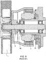
- a less widely employed bearing suspension mode is to utilize a single metallic tube to house the bearing pair, and to hang the rotor from one end in cantilever fashion, i.e., an outer rotor design.
- Fig. 8 illustrates a metallic tube T housing bearings B1, B2, and a rotor R supported by the bearings B1, B2 in cantilever fashion to support an impeller I.
- the metallic tube prevents a high speed magnetic rotor from being packaged between the bearings, i.e., an internal rotor design, because magnetic fields cannot effectively cross a metallic barrier without significant loss of flux density and/or increased heat.
- One aspect of the invention relates to a rotor supporting structure to support a rotor in use.
- Another aspect of the invention relates to a bearing arrangement having at least two bearing portions supported on a common member, e.g., bearing tube.
- a non-conductive material may be a material with relatively high resistivity (for example, in the vicinity of 2 micro Ohm-m or more) and a non-magnetic material may be a material with relatively low magnetic permeability (for example, in the vicinity of 2 or less).
- the acceptable ranges of these material characteristics may vary from case to case.
- the tube may be generally thermally conductive, and such tube can be metallic and/or non-metallic or semi-metallic.
- a brushless DC motor including a rotor, a magnet provided to the rotor, a pair of bearings to rotatably support the rotor, a stator assembly that at least partly surrounds the rotor and magnet thereof, and a bearing tube having an exterior surface and an interior surface that defines a tube interior.
- the stator assembly is adapted to control movement of the rotor.
- the stator assembly is provided along the exterior surface of the tube and the bearings are provided along the interior surface of the tube to support the rotor and magnet within the tube interior.
- the tube has at least a portion that is sufficiently magnetically transparent to allow a magnetic field to pass between the magnet and the stator assembly.
- a brushless DC motor including a rotor having a magnet, a stator assembly adapted to control movement of the rotor, and a tube provided between the rotor and the stator assembly.
- the tube has at least a portion that is sufficiently magnetically transparent to allow a magnetic field to pass between the magnet and the stator assembly.
- a brushless DC motor including a magnetic rotor rotatably supported between a pair of bearings, a stator assembly surrounding the rotor and adapted to control movement of the rotor, and a tube to retain the bearings and rotor within an interior of the tube.
- the tube has at least a portion that is sufficiently magnetically transparent to allow a magnetic field to pass between the magnetic rotor and the stator assembly.
- the PAP device for generating a supply of pressurized gas to be provided to a patient for treatment.
- the PAP device includes a housing, a core including a motor and at least one impeller, and a vibration isolation system to support the core within the housing in a flexible, vibration-isolated manner.
- the PAP device for generating a supply of pressurized gas to be provided to a patient for treatment.
- the PAP device includes a housing, a core including a motor and at least one impeller, and a vibration isolation system to support the core within the housing in a flexible, vibration-isolated manner.
- the vibration isolation system is adapted to be coupled to windings of a stator assembly to conduct current from an external source to the windings.
- a brushless DC motor including a rotor, a stator assembly surrounding the rotor and adapted to control movement of the rotor, a support structure to support the rotor and the stator assembly in an operative position, and a vibration isolation system provided to the support structure and adapted to support the support structure within a housing in a flexible, vibration-isolated manner.
- Another aspect of the invention relates to a method for manufacturing a motor.
- the method includes forming a tube having at least a portion that is sufficiently magnetically transparent to allow a magnetic field to pass through it, providing a magnetic rotor to an interior portion of the tube, and providing a stator assembly to an exterior portion of the tube to control movement of the magnetic rotor.
- Another aspect of the invention relates to a rotor supporting structure including at least one bearing support portion adapted to support a bearing and a sufficiently magnetically transparent portion to allow a magnetic field to pass through it.
- air will be taken to include breathable gases, for example air with supplemental oxygen. It is also acknowledged that the PAP devices described herein may be designed to pump fluids or gases other than air.
- Fig. 1 illustrates an electric motor or tube motor 10 according to an embodiment of the present invention.
- the motor 10 is in the form of a brushless DC motor.
- the motor 10 includes an optional housing 12, a rotatable shaft or rotor 14, a permanent magnet 16 mounted on the rotor 14, and a stator assembly 18 that surrounds the rotor 14 and magnet 16 thereof.
- the rotor 14 is rotatably supported by a pair of bearings 20 that are retained or housed by a bearing tube 22.
- the bearings 20 may be any suitable type as known in the art, e.g., conventional rolling element bearings, fluid bearings (air or liquid), sleeve bearings, or other type.
- the optional housing 12 encloses the stator assembly 18, rotor 14, magnet 16, bearings 20, and bearing tube 22.
- An end cap 24 is provided to the housing 12 to allow access to the housing interior and the components enclosed therein.
- the end cap 24 and end wall 26 of the housing each include an opening 28 to allow respective end portions 30, 32 of the rotor 14 to extend therethrough.
- Each end portion 30, 32 is adapted to be coupled to a device, e.g., impeller, to cause spinning movement of the device.
- the motor 10 may be structured such that only one end portion of the rotor 14 extends from the housing 12.
- an electronic controller typically provided as part of PAP devices or flow generators available from ResMed
- the bearing tube 22 comprises a relatively thin-walled, stationary, stable tube.
- the bearing tube 22 has at least a portion that is sufficiently magnetically transparent to allow a magnetic field to pass through it.
- such "magnetic transparency” may be provided by one or more the tube's material properties, e.g., non-electrically conductive, magnetically transparent or non-magnetic, and/or thermally conductive tube.
- such "magnetic transparency” may be provided by one or more perforations in the tube as described in greater detail below.
- non-electrically conductive, magnetically transparent, and thermally conductive may simply include one or more of these properties and/or a sufficient degree of these properties (e.g., partially electrically conductive and/or partially heat conductive).
- non-conductive refers to the (non)conduction of electricity, although the tube 22 may be heat conductive in embodiments, which may be beneficial for warming the air and/or cooling the blower elements.
- the tube includes adequate "magnetic transparency”, “non-electrical conductivity", and/or “thermal conductivity” to allow sufficient magnetic flux near the magnet without overheating.
- a non-conductive material is understood to be a material with relatively high resistivity (for example, in the vicinity of 2 micro Ohm-m or more) and a non-magnetic material is understood to be a material with relatively low magnetic permeability (for example, in the vicinity of 2 or less).
- the acceptable ranges of these material characteristics may vary, e.g., depending on application.
- the tube may be thermally conductive to allow heat release (heat may create drag on motor, inefficient power, reduced life on bearings, tube distortion, etc.).
- the tube may have different material properties along its length or circumference, e.g., different levels or regions of "magnetic transparency”, “non-electrical conductivity”, and/or “thermal conductivity.” That is, portions of the tube may have one or more of these properties, but other portions of the tube may not.
- Magnetic transparency should be greater in the vicinity of the magnet and stator assembly, where flux densities may be expected to be higher. Outside of that region, different properties could be tolerated and in some cases may not be necessary.
- the bearing tube 22 may be constructed of non-metallic materials, e.g., ceramics (e.g., stabilized zirconia), glass, polymers, filled (but non-conductive) polymers, or reinforced polymers (e.g., Fiberglass, Carbon, Boron, etc.).
- the tube can also be metallic or semi-metallic.
- the tube may include different materials along its length or circumference.
- the tube has a circular cross-sectional configuration along its length.
- the tube may have other suitable shapes, e.g., circular or round, square, polygonal, conical, etc.
- the tube may include one or more parts (e.g., multi-part construction), e.g., different elements with different properties that are fastened together.
- the tube may be sufficiently perforated (e.g., one or more holes, openings, and/or slits) to allow a magnetic field to pass through it.
- the tube may or may not include non-electrically conductive, magnetically transparent, and/or thermally conductive material properties.
- the tube may include any suitable combination of properties, materials, and/or shapes as described above.
- portions of the tube may have one or more of the features described above, but other portions of the tube may not.
- the stator assembly 18 is provided to a center portion 40 of the tube 22 along an exterior surface 42 thereof.
- the bearings 20 are provided to respective end portions 44, 46 of the tube 22 along an interior surface 48 thereof.
- the tube 22 retains the bearings 20 in substantially perfect axial alignment.
- the bearings 20 support the rotor 14 and magnet 16 within the tube interior.
- the magnet 16 is positioned between the bearings 20 such that the magnet 16 is aligned with the stator assembly 18.
- the inside diameter of the tube 22 is substantially similar to the outside diameter of the bearings 20. This allows the bearings 20 to be securely and stably retained within the tube 22, e.g., by friction fit, adhesive, etc.
- the tube 22 is sufficiently "magnetically transparent” (e.g., non-magnetic, non-electrically conductive, and/or thermally conductive), which allows the motor 10 to have a design in which the magnetic rotor 14 is located between the bearings 20 within the tube 22, as illustrated in Fig. 1 . That is, the stator assembly 18 can act on the magnetic rotor 14 positioned within the tube 22 without significant loss of flux density and/or increased heat, if any. Thus, the tube 22 provides stable physical properties and is adequate to support the needs of the motor application. It is noted that the bearing tube 22 may be incorporated into other motor arrangements or other applications where "magnetic transparency" may be beneficial.
- the motor arrangement of Fig. 1 in which the magnetic rotor 14 is positioned within the "magnetically transparent" tube, 22 has several advantages.
- the motor arrangement provides superior bearing-to-bearing alignment.
- the superior alignment results in improved noise and/or improved life.
- the superior alignment results in the ability to better accommodate fluid bearings, e.g., when the materials of the rotor and the tube have closely matched thermal expansion coefficients (e.g., both the tube and rotor may be made of stabilized zirconia).
- the motor arrangement also provides superior compactness (e.g., the rotor may reside between the tube mounted bearings, not cantilevered), superior dynamic response due to an inherently low inertia rotor, and superior rigidity due to simplicity of construction.
- the motor arrangement provides superior accommodation of both fluid bearings and a double-ended, impeller blower construction (e.g., when the motor is incorporated into a PAP device or flow generator as described below).
- one method for assembling bearings includes using a preload spring that applies a force to the bearings to ensure they remain correctly aligned and retained in position against the ends of tube, e.g., against flange 380 for the lower bearing and against tapered flange 382 for the upper bearing as shown Fig. 4-3 .
- the preload spring may be eliminated and the bearings may be retained in position by an adhesive, e.g., glue, or other suitable fixing means, e.g., mechanical fasteners, etc.
- the bearings may be of a range of varieties.
- the bearings could be constructed as sleeve types, duplex types, magnetic types, etc.
- a force may be applied (e.g., by spring 536 as indicated in dashed lines) to force the bearings 520, 525 against respective flanges 582, 580 and in correct alignment.
- an adhesive A e.g., glue, or other fixing means may be applied between the bearings 520, 525 and the tube 522 to fix and retain the bearings 520, 525 in position while the force is being applied, e.g., by the spring 536. Once the bearings 520, 525 are fixedly attached, the force may be removed.
- a potential problem with this alternative method is that when the motor warms up, different components (e.g., such as the rotor and the tube) will expand according to their individual thermal expansion coefficient which relates to the material used to make the components.
- different components e.g., such as the rotor and the tube
- the bearings may move or misalign causing an imbalance in the motor.
- the tube and the rotor may be made from the same material to have the same thermal expansion coefficient or the tube and the rotor may be made from two different materials with the same thermal expansion coefficient.
- the motor 10 may be incorporated into a PAP device or flow generator structured to generate a supply of pressurized gas to be provided to a patient for treatment, e.g., of Sleep Disordered Breathing (SDB) with Non-Invasive Positive Pressure Ventilation (NIPPV).
- SDB Sleep Disordered Breathing
- NIPPV Non-Invasive Positive Pressure Ventilation
- the motor may be constructed to operate up to about 30,000 rpm and/or 8 mNm torque.
- Fig. 2 is a schematic view of a PAP device or flow generator 60 including the motor 10.
- the PAP device 60 includes a housing 62 and a blower 64 supported within the housing 62.
- the blower 64 is operable to draw a supply of gas into the housing 62 through one or more intake openings (not shown, but typically provided at the bottom or side wall of the flow generator housing) and provide a pressurized flow of gas at an outlet 66.
- the supply of pressurized gas is delivered to the patient via an air delivery conduit that includes one end coupled to the outlet 66 of the PAP device 60 and an opposite end coupled to a mask system that comfortably engages the patient's face and provides a seal.
- the blower is constructed to deliver pressurized gas suitable for CPAP or NIPPV, e.g., in the range of 4-28 cmH 2 O, at flow rates of up to 180 L/min (measured at the mask), depending on patient requirements.
- the blower may be configured to deliver bilevel therapy or variable pressure therapy (e.g., low range of 2-6 cmH 2 O and high range of 6-30 cmH 2 O).
- the blower 64 is supported by or within the housing 62, and includes at least one impeller 68 and the motor 10 to drive the at least one impeller 68.
- the blower 64 has a double-ended, impeller blower construction.
- the motor 10 includes the arrangement shown in Fig. 1 , and each end portion 30, 32 of the rotor 14 is coupled to an impeller 68.
- the blower 64 may include a single impeller coupled to the motor 10.
- the motor may incorporated into blower assemblies such as those disclosed in U.S. Patent No. 6,910,483 , U.S. Patent Publication No. 2005/0103339 , and U.S. Provisional Patent Applications 60/730,875 , entitled “Multiple Stage Blowers and Nested Volutes Thereof” filed October 28, 2005, and 60/775,333 , entitled “Blower Motor with Flexible Support Sleeve” filed February 22, 2006, each of which is incorporated herein by reference in its entirety.
- the motor 10 may be employed in other applications.
- a PAP device or flow generator 60 including the motor arrangement of Fig. 1 has several advantages.
- the motor arrangement of Fig. 1 provides a quieter, longer life, smaller, more reliable, and highly responsive PAP device. This provides a PAP device that is more comfortable and easier to use for the patient. Because the patients are more satisfied, therapy is easier to administer for the physician.
- the PAP device 60 including the motor arrangement of Fig. 1 provides a potentially lower cost due to reduced parts count and less machining, a superior motor platform for implementing conventional rolling element bearings, a motor platform to accommodate fluid bearings, a motor platform to accommodate fluid bearings and a double-ended, impeller blower construction, and/or a motor platform to accommodate fluid bearings and a double-ended, impeller blower construction and integral volutes and/or blower housings.
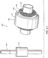
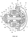
- Figs. 3-1 and 3-2 illustrate an electric motor or tube motor 210 according to another embodiment of the present invention.
- the tube motor 210 is substantially similar to the tube motor 10 described above, and also illustrates the motor's ability to function as a motor without the requirement of a housing or endcap.
- the motor 210 includes a rotatable shaft or rotor 214 including a permanent magnet 216 provided thereto, a "magnetically transparent" bearing tube 222 structured to retain or house bearings 220 that rotatably support the rotor 214 within the tube 222, and a stator assembly 218 provided along an exterior surface of the tube 222 (e.g., retained on tube by friction).
- the stator assembly 218 includes windings 219, a stator or stator lamination stack 221 provided to the windings 219, and one or more insulators 223 provided between the windings 219 and the stack 221 to insulate the stack 221 from the windings 219.
- the tube 222 is "magnetically transparent", which allows the stator assembly 218 to act on the magnetic rotor 214 positioned within the tube 222 without significant loss of flux density and/or increased heat, if any.
- a spacer 234 is provided between the rotor magnet 216 and one of the bearings 220, and a spring or biasing element 236 is provided between the rotor magnet 216 and the other of the bearings 220. This arrangement maintains alignment of the rotor magnet 216 with the stator assembly 218.
- the housing elements are replaced by a single tube 222 that extends through the core of the stator assembly 218.
- the tube 22 is thin-walled (but strong) and is “magnetically transparent", which allows the bearings to be mounted within a single bore with the rotor magnet nested therebetween.
- the rotor's magnetic flux penetrates the wall of the tube (since the tube is “magnetically transparent”) to interact with stator winding currents to produce shaft torque.
- the "tube motor” is self-contained wherein the stator and rotor are supported and/or contained by the tube in a manner that allows the tube motor to function as a motor. That is, a housing or endcap is not needed to support and/or contain the stator and/or rotor, e.g., housing not needed to support motor bearings. In PAP devices, a housing and/or endcap may be provided to the tube motor to define a plenum chamber for pressurized gas.
- Benefits and features of the tube motor 210 include one or more of the following:
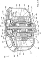
- Figs. 4-1 to 4-3 illustrate a PAP device or blower 360 according to another embodiment of the present invention.
- the PAP device 360 includes a volute or housing 362 that defines a generally spiral-shaped channel 363, a tube motor 310 including a "magnetically transparent" tube 322 support by or within the housing 362, an impeller 368 provided to the rotor 314 of the tube motor 310, and a lid or end cap 365 provided to the housing 362 to enclose the impeller 368.
- the PAP device 360 is operable to draw a supply of gas into the housing through an inlet 367 and provide a pressurized flow of gas at an outlet 366.
- the PAP device 360 is generally cylindrical with the inlet 367 aligned with an axis of the PAP device and the outlet 366 structured to direct gas exiting the PAP device in a generally tangential direction.
- the PAP device 360 may have a diameter of about 60 mm and a height of about 30 mm, which provides a cylindrical volume of about 85 cm 3 .
- the outlet 366 may have a diameter of about 10 mm. It is to be understood that these dimensions are merely exemplary and other dimensions are possible depending on application.
- the tube motor 310 includes a rotatable shaft or rotor 314 including a permanent magnet 316 provided thereto, a "magnetically transparent" tube 322 structured to retain or house bearings 320, 325 that rotatably support the rotor 314 within the tube 322, and a stator assembly 318 provided along an exterior surface of the tube 322 (e.g., retained on tube by friction).
- the stator assembly includes windings 319, a stator or stator lamination stack 321 (e.g., slotless or toothless) provided to the windings 319, and one or more insulators 323 provided between the windings 319 and the stack 321 to insulate the stack 321 from the windings 319. Further details of coil winding is disclosed in U.S. Provisional Application No. 60/877,373, filed December 28, 2006 , which is incorporated herein by reference in its entirety.
- the tube 322 of the tube motor 310 includes a tube portion 370, a shield 372 provided to one end of the tube portion 370, and an annular flange 374 extending from the shield 372.
- the tube 322 is integrally molded (e.g., injection molded) as a one-piece structure.
- the tube 322 may be constructed in other suitable manners.
- the tube portion 370 of the tube 322 is structured to retain and align the bearings 320, 325 that rotatably support the rotor 314.
- the tube portion 370 is structured such that mixed bearing sizes may be used.
- the upper end of the tube portion 370 is structured to support bearing 320 and the lower end of the tube portion 370 is structured to support bearing 325 having a smaller size or diameter than bearing 320.
- the upper end of the tube portion 370 includes an annular surface 376 defining a diameter D and adapted to support bearing 320.
- the lower end of the tube portion 370 includes an annular surface 378 defining a smaller diameter d and adapted to support bearing 325.
- the one-piece tube portion 370 provides accurate bore-to-bore alignment which provides accurate bearing-to-bearing alignment.
- the upper end of the tube portion 370 also includes one or more extensions 338 structured to strengthen the upper end of the tube portion 370 supporting the bearing 320.
- the tube portion may be manufactured such that substantially no draft angle is provided along surfaces 376, 378 adapted to support respective bearings 320, 325. However, a draft angle may be provided along the surface between surfaces 376 and 378 to facilitate molding along the line of draw.
- a sloped surface 377 may be provided between surfaces 376, 378 to guide the rotor 314 (with bearings 320, 325 provided to respective end portions) into the lower end of the tube portion 370.
- the smaller bearing side of the rotor 314 may be inserted into or "dropped into” the tube portion 370 through the upper end of the tube portion 370.
- the sloped surface 377 will guide the bearing 325 into engagement with surface 378 having a reduced diameter.
- the bearing 325 is self-guided into its operative position.
- the lower end of the tube portion 370 includes a flange 380 that provides a stop or support for the bearing 325 at the lower end.
- the upper end of the tube portion 370 includes one or more tapered flange portions 382 adapted to engage the bearing 320, and hence retain the rotor within the tube portion 370.
- the tapered flange portions 382 provide snap-in bearing retention. That is, the tapered flange portions 382 may be resiliently deflected upon rotor assembly to allow the bearing 320 to snap into the tube portion 370, but prevent removal of the bearing 320 (and hence the rotor) from the tube portion 370 once assembled.
- a spring or biasing element 336 may be provided between the bearing 320 and the rotor magnet 316 to maintain alignment of the rotor magnet 316 with the stator assembly 318.
- the shield 372 of the tube 322 forms an upper wall or cutoff for the channel 363 that directs pressurized gas to the outlet 366.
- the shield 372 is in the form of a circular disk that is provided to (e.g., integrally formed in one-piece) an end of the tube portion 370 adjacent the impeller 368.
- the outer edge of the shield 372 substantially aligns with or extends radially beyond the outer edge of the impeller 368.
- the shield 372 provides a narrow annular gap 385 (e.g., about 1 mm) between its outer edge and the wall of the housing 362, which is sufficient to direct gas into the channel 363 leading to the outlet 366.
- the tube motor 310 and the housing 362 provide complementary structural elements that are adapted to support, align, and/or contain the tube motor 310 within the housing 362.
- the housing 362 includes one or more slots 384 in an upper portion of the housing wall that is adapted to receive respective tabs 386 provided along the outer edge of the shield 372 (e.g., see Fig. 4-1 ).
- the shield 372 includes three tabs 386 that are received in respective slots 384 of the housing 362.
- any suitable number of slots/tabs may be provided.
- the housing 362 and tube 322 cooperate to support and maintain the stator assembly 318 in an operative position.
- the annular flange 374 of the tube 322 is structured to enclose an upper portion of the windings 319 and engage an upper side of the stack 321.
- the bottom wall of the housing 362 includes an annular flange 388 that is structured to enclose a lower portion of the windings 319 and engage a lower side of the stack 321.
- the annular flanges 374, 388 cooperate to enclose and sandwich the stator assembly 318 between the housing 362 and the tube 322.
- each flange 374, 388 includes one or more anchoring protrusions 390 (also referred to as anchoring pips or locating pins) that are adapted to engage within corresponding holes 391 provided through the stack 321.
- anchoring protrusions 390 also referred to as anchoring pips or locating pins
- This arrangement self-adheres and/or aligns the housing 362 and the tube 322 to the stack 321.
- exterior surfaces of the flanges 374, 388 are substantially flush with an exterior surface of the stack 321.
- the bottom wall of the housing 362 includes an opening 392 adapted to receive the lower end of the tube portion 370 of the tube 322.
- One or more tabs 394 may be provided along the edge of the opening 392 that are adapted to engage within respective openings 396 provided in the lower end of the tube portion 370.
- the above-described complementary structural elements provided to the tube motor 310 and the housing 362 may provide snap-fit retention.
- the PAP device 360 includes a single impeller 368.
- the impeller 368 includes a plurality of continuously curved or straight blades 369 sandwiched between a pair of disk-like shrouds 371, 373.
- the smaller shroud 373 incorporates the hub or bushing 375 that is adapted to receive an end portion of the rotor 314. Further details of impellers are disclosed in PCT Application No. PCT/AU2006/001617, filed October 27, 2006 , which is incorporated herein by reference in its entirety.
- a gap G (e.g., see Fig. 4-3 ) may be controlled by a press-to-shim technique.
- a shim 333 may be provided along the upper end of the tube 322 that is adapted to engage the lower end of the hub 375 of the impeller 368 (as the hub 375 is mounted to the rotor 314) and hence control the size of the gap G.
- the impeller 368 may have a diameter of about 50 mm. It is to be understood that this dimension is merely exemplary and other dimensions are possible depending on application.
- a balance ring 398 may be optionally provided to an opposite end portion of the rotor 314 (opposite the end portion supporting the impeller 368).
- This arrangement may facilitate single-plane or two-plane balancing of the tube motor 310.
- the gap 385 between the outer edge of the shield 372 and the wall of the housing 362 allows gas to pass into the channel 363 and down around the sides of the tube motor 310. Gas passes around the channel 363 and the sides of the tube motor 310 flowing in a spiral manner with towards the outlet 366.
- the exterior surface of the stack 321 of the stator assembly 318 is exposed to the channel 363 of the housing 362 and hence is exposed to the gas passing through the channel 363. This arrangement allows forced-convection cooling of the stack 321 as gas flows through the channel 363 in use.
- the PAP device 360 includes a relatively basic construction with a single impeller to provide relatively basic CPAP and/or SnorePAP treatment.
- the PAP device 360 provides four plastic molded (e.g., injection-molded) parts, i.e., the housing 362, the tube 322, the impeller 368, and the end cap 365. These molded parts (along with the rotor 314, stator assembly 318, bearings 320, 325, and spring 336) provide an arrangement with relatively low component and assembly costs.
- plastic molded e.g., injection-molded
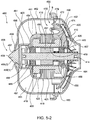
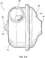
- Figs. 5-1 to 5-6 illustrate a PAP device or blower 460 (e.g., to provide CPAP through BiLevel NIV treatment) according to another embodiment of the present invention.
- the PAP device 460 includes a housing 462 and a core 461 supported within the housing 462 by a vibration isolation system 455.
- the vibration isolation system 455 supports the core 461 in a flexible, vibration-isolated manner with respect to the housing 462 so that the core 461 is substantially isolated from the housing 463.
- vibrations and/or other movement generated by the core 461 in use are substantially isolated from the housing 462.
- the core 461 includes a tube motor 410 including a "magnetically transparent" tube 422, a core housing 450 structured to substantially enclose the tube motor 410, an impeller 468 provided to one end portion of the rotor 414 of the tube motor 410, and a balance ring 498 provided to an opposite end portion of the rotor 414.
- the tube motor 410 includes a rotatable shaft or rotor 414 including a permanent magnet 416 provided thereto, a "magnetically transparent" tube 422 structured to retain or house bearings 420 that rotatably support the rotor 414 within the tube 422, and a stator assembly 418 provided along an exterior surface of the tube 422 (e.g., retained on tube by friction).
- the stator assembly 418 includes windings 419, a stator or stator lamination stack 421 (e.g., slotless or toothless) provided to the windings 419, and one or more insulators 423 provided between the windings 419 and the stack 421 to insulate the stack 421 from the windings 419.
- a stator or stator lamination stack 421 e.g., slotless or toothless
- insulators 423 provided between the windings 419 and the stack 421 to insulate the stack 421 from the windings 419.
- a spring or biasing element 436 may be provided between one of the bearings 420 and the rotor magnet 416 to maintain alignment of the rotor magnet 416 with the stator assembly 418.
- the core housing 450 includes a first housing part 452 provided to one end of the tube 422 and a second housing part 454 provided to the opposite end of the tube 422.
- the first housing part 452 includes a shield 472 that forms an upper wall or cutoff for the housing channel 463.
- An inner annular flange 474 and an outer annular flange 479 extend from the shield 472.
- the shield 472 and impeller 468 have a tapered or sloped configuration along its radial length.
- other suitable configurations of the shield and impeller are possible.
- the shield 472 provides a narrow annular gap 485 between its outer edge and the housing 462, which is sufficient to direct gas into the housing channel 463.
- the shield 472 includes an opening that allows one end portion of the rotor 414 to pass therethrough.
- the edge of the opening includes an annular slot 484 that is adapted to receive one end of the tube 422.
- the inner annular flange 474 is structured to enclose an upper portion of the windings 419 and engage an upper side of the stack 421.
- the inner annular flange 474 includes one or more anchoring protrusions 490 that are adapted to engage within corresponding holes 491 provided through the stack 421.
- the second housing part 454 includes a main wall 487 and an annular flange 488 extending from the main wall 487.
- the main wall 487 includes an opening that allows the opposite end portion of the rotor 414 to pass therethrough.
- the edge of the opening includes an annular slot 489 that is adapted to receive the opposite end of the tube 422.
- annular flange 488 is structured to enclose a lower portion of the windings 419 and engage a lower side of the stack 421.
- the annular flange 488 includes one or more anchoring protrusions 493 that are adapted to engage within corresponding holes 491 provided through the stack 421.
- the flanges 474, 488 cooperate to enclose and sandwich the stator assembly 418.
- exterior surfaces of the flanges 474,488 are substantially flush with an exterior surface of the stack 421, i.e., exterior surface of stack exposed. As described above, this arrangement allows forced-convection cooling of the stack 421 as gas flows through the housing channel 463 in use.
- the core housing 450 also includes a cap 495 provided to the second housing part 454 and adapted to enclose the balance ring 498 at one end portion of the rotor 414.
- one or portions of the core housing 450 may be integrally formed in one piece with the tube 422, e.g., similar to tube 322 described above.
- the housing 462 includes a main body 481 that provides an outer wall for the housing channel 463 and a lid or end cap 465 provided to the main body 481 to enclose the core 461.
- the PAP device 460 is operable to draw a supply of gas into the housing through an inlet 467 and provide a pressurized flow of gas at an outlet 466.
- the PAP device 460 is generally cylindrical with the inlet 467 aligned with an axis of the PAP device and the outlet 466 structured to direct gas exiting the PAP device in a generally tangential direction.
- the vibration isolation system 455 includes a front suspension 456 (or front vibration isolator) to support a front portion of the core 461 and a rear suspension 458 (or rear vibration isolator) to support a rear portion of the core 461.
- the front and rear suspension 456, 458 together support the core 461 in a flexible, vibration-isolated manner with respect to the housing 462.
- the front suspension 456 includes a plurality of biasing elements 457, e.g., flat springs. As best shown in Fig. 5-3 , each biasing element 457 includes one end portion 457(1) provided to the outer annular flange 479 of the shield 472 of the core 461, an opposite end portion 457(2) provided to the main body 481 of the housing 462, and an intermediate portion 457(3) that provides a flexible structure to isolate the core 461 from the housing 462.
- biasing elements 457 e.g., flat springs.
- each biasing element 457 includes one end portion 457(1) provided to the outer annular flange 479 of the shield 472 of the core 461, an opposite end portion 457(2) provided to the main body 481 of the housing 462, and an intermediate portion 457(3) that provides a flexible structure to isolate the core 461 from the housing 462.
- the one end portion 457(1) includes a bent configuration adapted to receive the free end of the flange 479.
- the opposite end portion 457(2) includes a bent configuration adapted to engage within a slot 483 provided to the main body 481.
- the intermediate portion 457(3) is bent into a concertina or bellow-like configuration to provide a flexible structure.
- the biasing elements 457 support the front portion of the core 461 within the housing 462 while isolating the core 461 from the housing 462, e.g., vibration isolated.
- wire W from the windings 419 may be coupled to one or more of the biasing elements 457, e.g., wire W connected to the end portion 457(1).
- the biasing elements 457 e.g., flat springs formed of metal
- Figs. 5-1 and 5-2 illustrate external source S that may be coupled to end portion 457(2) to conduct current through the biasing element 457 and to wire W from windings 419.
- the rear suspension 458 is in the form of a resiliently flexible nipple 459 (e.g., formed of a silicone material) having one end 459(1) provided to the cap 495 of the core housing 450 and an opposite end 459(2) provided to the main body 481 of the housing 462.
- a resiliently flexible nipple 459 e.g., formed of a silicone material
- the end 459(2) includes an annular recess 497 adapted to receive the edge of an opening 499 provided in the lower wall of the main body 481.
- the resiliently flexible nipple 459 support the rear portion of the core 461 within the housing 462 while isolating the core 461 from the housing 462, e.g., vibration isolated.
Landscapes
- Health & Medical Sciences (AREA)
- Engineering & Computer Science (AREA)
- Power Engineering (AREA)
- General Health & Medical Sciences (AREA)
- Veterinary Medicine (AREA)
- Biomedical Technology (AREA)
- Heart & Thoracic Surgery (AREA)
- Hematology (AREA)
- Life Sciences & Earth Sciences (AREA)
- Animal Behavior & Ethology (AREA)
- Pulmonology (AREA)
- Public Health (AREA)
- Anesthesiology (AREA)
- Emergency Medicine (AREA)
- Connection Of Motors, Electrical Generators, Mechanical Devices, And The Like (AREA)
- Motor Or Generator Frames (AREA)
- Respiratory Apparatuses And Protective Means (AREA)
- Magnetic Bearings And Hydrostatic Bearings (AREA)
- Structures Of Non-Positive Displacement Pumps (AREA)
- Brushless Motors (AREA)
Priority Applications (1)
| Application Number | Priority Date | Filing Date | Title |
|---|---|---|---|
| EP20217506.3A EP3871721B1 (de) | 2006-10-24 | 2007-10-24 | Bürstenloser gleichstrommotor mit lagern |
Applications Claiming Priority (4)
| Application Number | Priority Date | Filing Date | Title |
|---|---|---|---|
| US85377806P | 2006-10-24 | 2006-10-24 | |
| US92955807P | 2007-07-03 | 2007-07-03 | |
| PCT/US2007/022474 WO2008051534A2 (en) | 2006-10-24 | 2007-10-24 | Brushless dc motor with bearings |
| EP07861481.5A EP2076681B1 (de) | 2006-10-24 | 2007-10-24 | Bürstenloser gleichstrommotor mit lagern |
Related Parent Applications (2)
| Application Number | Title | Priority Date | Filing Date |
|---|---|---|---|
| EP07861481.5A Division EP2076681B1 (de) | 2006-10-24 | 2007-10-24 | Bürstenloser gleichstrommotor mit lagern |
| EP07861481.5A Division-Into EP2076681B1 (de) | 2006-10-24 | 2007-10-24 | Bürstenloser gleichstrommotor mit lagern |
Related Child Applications (1)
| Application Number | Title | Priority Date | Filing Date |
|---|---|---|---|
| EP20217506.3A Division EP3871721B1 (de) | 2006-10-24 | 2007-10-24 | Bürstenloser gleichstrommotor mit lagern |
Publications (2)
| Publication Number | Publication Date |
|---|---|
| EP3144025A1 true EP3144025A1 (de) | 2017-03-22 |
| EP3144025B1 EP3144025B1 (de) | 2020-12-30 |
Family
ID=39325160
Family Applications (3)
| Application Number | Title | Priority Date | Filing Date |
|---|---|---|---|
| EP20217506.3A Active EP3871721B1 (de) | 2006-10-24 | 2007-10-24 | Bürstenloser gleichstrommotor mit lagern |
| EP07861481.5A Active EP2076681B1 (de) | 2006-10-24 | 2007-10-24 | Bürstenloser gleichstrommotor mit lagern |
| EP16192838.7A Active EP3144025B1 (de) | 2006-10-24 | 2007-10-24 | Pap gerät |
Family Applications Before (2)
| Application Number | Title | Priority Date | Filing Date |
|---|---|---|---|
| EP20217506.3A Active EP3871721B1 (de) | 2006-10-24 | 2007-10-24 | Bürstenloser gleichstrommotor mit lagern |
| EP07861481.5A Active EP2076681B1 (de) | 2006-10-24 | 2007-10-24 | Bürstenloser gleichstrommotor mit lagern |
Country Status (8)
| Country | Link |
|---|---|
| US (4) | US8638014B2 (de) |
| EP (3) | EP3871721B1 (de) |
| JP (2) | JP5296696B2 (de) |
| KR (3) | KR101525531B1 (de) |
| CN (2) | CN102931798B (de) |
| AU (1) | AU2007309509B2 (de) |
| NZ (3) | NZ596357A (de) |
| WO (1) | WO2008051534A2 (de) |
Cited By (1)
| Publication number | Priority date | Publication date | Assignee | Title |
|---|---|---|---|---|
| DE102019122458A1 (de) * | 2019-08-21 | 2021-02-25 | Minebea Mitsumi Inc. | Elektromotor mit abgedichtetem Gehäuse |
Families Citing this family (224)
| Publication number | Priority date | Publication date | Assignee | Title |
|---|---|---|---|---|
| CN102931798B (zh) | 2006-10-24 | 2016-01-20 | 瑞思迈发动机及马达技术股份有限公司 | 具有轴承的无刷直流电动机 |
| AU2008202487B2 (en) | 2007-06-05 | 2013-07-04 | Resmed Motor Technologies Inc. | Blower with Bearing Tube |
| TWM334625U (en) * | 2008-01-03 | 2008-06-11 | Sunonwealth Electr Mach Ind Co | Easily being activated structure of miniature fan |
| US9248248B2 (en) * | 2009-07-17 | 2016-02-02 | Paftec Technologies Pty Ltd | Respirator |
| CN102893136A (zh) * | 2010-03-19 | 2013-01-23 | Abb有限公司 | 用于传动的健康监测方法和系统 |
| KR101709550B1 (ko) * | 2010-05-12 | 2017-02-23 | 엘지전자 주식회사 | 비엘디시 모터 및 이를 이용한 배수펌프 |
| JP2012087748A (ja) * | 2010-10-22 | 2012-05-10 | Nippon Densan Corp | 送風ファン |
| EP3747489B1 (de) * | 2011-02-25 | 2024-03-27 | ResMed Motor Technologies Inc | Gebläse und pap-system |
| EP4269806A3 (de) | 2011-04-18 | 2024-01-17 | ResMed Motor Technologies Inc. | Pap-systemgebläse |
| CN117045914A (zh) | 2011-07-13 | 2023-11-14 | 费雪派克医疗保健有限公司 | 加压气体源 |
| US10137264B2 (en) | 2011-07-13 | 2018-11-27 | Fisher & Paykel Healthcare Limited | Respiratory assistance apparatus |
| NZ718377A (en) * | 2012-03-06 | 2017-11-24 | Resmed Motor Technologies Inc | Flow generator |
| BR112015001899A2 (pt) | 2012-07-27 | 2017-07-04 | Resmed Ltd | interface de paciente e método para produzir a mesma. |
| JP5211302B1 (ja) * | 2012-09-03 | 2013-06-12 | 株式会社メトラン | 送風機 |
| NZ630754A (en) | 2012-11-16 | 2016-12-23 | Resmed Ltd | Positioning and stabilising structure for a patient interface system |
| US20150320954A1 (en) * | 2012-12-17 | 2015-11-12 | Nidec Copal Electronics Corporation | Cpap device |
| AU2013101734A4 (en) | 2012-12-18 | 2015-09-24 | Fisher & Paykel Healthcare Limited | Impeller and motor assembly |
| CN203989377U (zh) | 2013-01-16 | 2014-12-10 | 瑞思迈有限公司 | 患者接口、定位和稳定结构、患者连接系统以及缓冲构件 |
| FR3001155B1 (fr) * | 2013-01-22 | 2015-12-25 | Air Liquide Medical Systems | Appareil d'assistance respiratoire avec turbine insonorisee |
| EP4079363B1 (de) | 2013-03-15 | 2025-08-27 | ResMed Pty Ltd | Druckbeatmungsvorrichtung |
| US9861778B2 (en) | 2013-03-15 | 2018-01-09 | Resmed Limited | Humidifier reservoir |
| NZ714593A (en) | 2013-04-12 | 2017-08-25 | Resmed Ltd | Neck strap, crown strap assembly and headgear for a breathing mask |
| CN108187208B (zh) | 2013-06-25 | 2022-03-01 | 瑞思迈私人有限公司 | 出气口连接组件及其制造方法 |
| US10549060B2 (en) | 2013-06-25 | 2020-02-04 | ResMed Pty Ltd | Outlet connection assembly and method of making the same |
| AU2014295910A1 (en) | 2013-07-29 | 2016-02-04 | Resmed Limited | Heat and moisture exchanger for a patient interface |
| NZ718810A (en) | 2013-10-03 | 2017-10-27 | Resmed Ltd | Mask vent with side wall |
| FR3011697A1 (fr) * | 2013-10-07 | 2015-04-10 | Moving Magnet Tech | Machine electrique sans encoches a bobinage concentre |
| NZ717147A (en) | 2013-10-21 | 2017-08-25 | Resmed Ltd | Methods of detecting a quantity of water in a humidifier |
| EP4378507B1 (de) | 2013-11-15 | 2026-07-22 | ResMed Pty Ltd | Patientenschnittstelle |
| TWI663995B (zh) | 2013-12-17 | 2019-07-01 | 澳大利亞商瑞思邁私人股份有限公司 | 呼吸壓治療系統 |
| US9929608B2 (en) * | 2014-02-07 | 2018-03-27 | Nidec Motor Corporation | Stator cage for large motor |
| CN111481797B (zh) | 2014-03-13 | 2023-03-21 | 瑞思迈私人有限公司 | 用于呼吸治疗装置的湿化器 |
| USD762843S1 (en) | 2014-03-18 | 2016-08-02 | Resmed Limited | Air delivery tube |
| JP6693888B2 (ja) | 2014-04-23 | 2020-05-13 | レスメド・プロプライエタリー・リミテッド | 患者インタフェースにおいて湿度を保持する装置 |
| NZ630742A (en) | 2014-05-01 | 2016-02-26 | Resmed Ltd | A patient interface |
| NZ630751A (en) | 2014-05-01 | 2016-03-31 | ResMed Humidification Technologies GmbH | Humidifying chamber for humidifying breathable gas |
| JP6373059B2 (ja) * | 2014-05-21 | 2018-08-15 | 株式会社不二工機 | マグネットロータ式モータ及び当該モータを含むポンプ |
| US10596340B2 (en) | 2014-06-17 | 2020-03-24 | ResMed Pty Ltd | Seal forming structure for a patient interface and a tool and method of manufacturing the seal forming structure |
| NZ798329A (en) | 2014-06-19 | 2024-10-25 | ResMed Pty Ltd | Patient interface for respiratory therapy |
| EP3903867B1 (de) | 2014-07-02 | 2025-11-05 | ResMed Pty Ltd | Angepasste patientenschnittstelle |
| NZ630757A (en) | 2014-08-01 | 2016-03-31 | Resmed Ltd | Self-optimising respiratory therapy system |
| NZ766323A (en) | 2014-08-01 | 2022-05-27 | Resmed Inc | Patient management system |
| TW201612845A (en) | 2014-08-28 | 2016-04-01 | Resmed Ltd | Method, system and apparatus for diagnosis, monitoring and treatment of respiratory disorders |
| JP2017529158A (ja) | 2014-09-16 | 2017-10-05 | レスメド・リミテッドResMed Limited | スペーサ織物を含むヘッドギア |
| NZ730258A (en) | 2014-09-18 | 2023-03-31 | ResMed Pty Ltd | Gas washout vent for patient interface |
| EP3212262B1 (de) | 2014-10-27 | 2020-02-26 | ResMed Pty Ltd | Vorrichtung zur behandlung von übererregungsstörungen |
| US10125791B2 (en) | 2014-11-17 | 2018-11-13 | Nidec Corporation | Blower |
| EP3223894B1 (de) | 2014-11-26 | 2020-12-23 | ResMed Pty Ltd | Textile patientenschnittstelle |
| US10744295B2 (en) | 2015-01-13 | 2020-08-18 | ResMed Pty Ltd | Respiratory therapy apparatus |
| WO2016119018A1 (en) | 2015-01-30 | 2016-08-04 | Resmed Asia Operations Pty Limited | Patient interface comprising a gas washout vent |
| WO2016139645A1 (en) | 2015-03-05 | 2016-09-09 | Resmed Limited | A humidifier for a respiratory therapy device |
| CN111420269B (zh) | 2015-03-10 | 2023-05-05 | 瑞思迈私人有限公司 | 具有面部密封的流体连接器 |
| EP3268073B1 (de) | 2015-03-13 | 2023-12-20 | ResMed Pty Ltd | Atemtherapievorrichtung und computerprogramm |
| CN107530514B (zh) | 2015-03-20 | 2020-08-11 | 瑞思迈私人有限公司 | 用于呼吸障碍的通气治疗的方法和装置 |
| WO2016151556A2 (en) * | 2015-03-24 | 2016-09-29 | Padmini Vna Mechatronics Pvt. Ltd. | An improved bldc water pump minimizing attrition on shaft |
| NZ774237A (en) | 2015-03-25 | 2023-12-22 | ResMed Pty Ltd | Patient interface with blowout prevention for seal-forming portion |
| EP4186548A1 (de) | 2015-04-02 | 2023-05-31 | Hill-Rom Services PTE. LTD. | Maskenleckdetektion für eine atemvorrichtung |
| EP3985260B1 (de) | 2015-06-16 | 2024-09-18 | ResMed Pty Ltd | Laufrad mit geneigten und umgekehrt geneigten schaufeln |
| EP3319675B1 (de) | 2015-07-07 | 2020-11-04 | ResMed Pty Ltd | Vorrichtung für atemwegsdrucktherapie |
| US11077273B2 (en) | 2015-07-20 | 2021-08-03 | ResMed Pty Ltd | Patient interface with volume reducing member |
| CN116036435A (zh) | 2015-07-24 | 2023-05-02 | 瑞思迈私人有限公司 | 具有覆盖边缘的头带 |
| CN107920608A (zh) | 2015-07-24 | 2018-04-17 | 瑞思迈有限公司 | 具有覆盖边缘的头带 |
| EP3334485B1 (de) | 2015-08-14 | 2024-03-06 | ResMed Pty Ltd | Überwachung der atemdrucktherapie |
| CN112657030B (zh) | 2015-09-23 | 2024-10-22 | 瑞思迈私人有限公司 | 包括具有不同厚度的密封形成结构的患者接口 |
| EP3352829B1 (de) | 2015-09-23 | 2022-12-28 | ResMed Pty Ltd | Ellbogenanordnung |
| US10799661B2 (en) | 2015-09-23 | 2020-10-13 | ResMed Pty Ltd | Patient interface with a seal-forming structure having varying thickness |
| JP6896741B2 (ja) | 2015-09-23 | 2021-06-30 | レスメド・プロプライエタリー・リミテッド | 患者インターフェース |
| EP4043057B1 (de) | 2015-09-23 | 2024-01-03 | ResMed Pty Ltd | Patientenschnittstelle mit einer dichtungsbildenden struktur mit unterschiedlicher dicke |
| NZ740229A (en) | 2015-09-23 | 2023-07-28 | ResMed Pty Ltd | Patient interface with foam seal-forming structure |
| EP3352830B1 (de) | 2015-09-23 | 2021-04-28 | ResMed Pty Ltd | Entlüftungsadapter für ein atemtherapiesystem |
| EP3146991B1 (de) | 2015-09-25 | 2022-01-26 | ResMed Pty Ltd | Patientenschnittstellenkomponenten |
| US10821257B2 (en) | 2015-10-05 | 2020-11-03 | ResMed Pty Ltd | Respiratory system with humidifier and conformable reservoir |
| US11504492B2 (en) | 2015-10-08 | 2022-11-22 | ResMed Pty Ltd | Air conduit for a respiratory device |
| ITUB20155296A1 (it) * | 2015-10-19 | 2017-04-19 | Dab Pumps Spa | Attrezzatura per l'assemblaggio di un motore elettrico a magneti permanenti da impiegare particolarmente in dispositivi di pompaggio, motore elettrico realizzato con tale attrezzatura, ed elettropompa comprendente tale motore elettrico |
| CN105186745A (zh) * | 2015-10-29 | 2015-12-23 | 泰锐菲克(天津)医疗科技有限公司 | 一种电机转子装配结构及带有该结构的气流发生器 |
| EP3386576B1 (de) | 2015-12-10 | 2021-02-17 | ResMed Pty Ltd | Vorrichtung zur atembehandlung |
| EP3402560B1 (de) | 2016-01-14 | 2022-03-23 | ResMed Pty Ltd | Oro-nasale patientenschnittstelle |
| WO2017124152A1 (en) | 2016-01-21 | 2017-07-27 | Resmed Limited | Adjustable headgear tubing for a patient interface |
| USD805630S1 (en) | 2016-02-02 | 2017-12-19 | Resmed Limited | Air delivery tube |
| EP3912554B1 (de) | 2016-02-02 | 2026-04-29 | ResMed Pty Ltd | Verfahren und vorrichtung zur behandlung von atemwegserkrankungen |
| JP6409248B2 (ja) * | 2016-03-28 | 2018-10-24 | ミネベアミツミ株式会社 | モータ |
| EP3858551A1 (de) | 2016-03-30 | 2021-08-04 | Milwaukee Electric Tool Corporation | Bürstenloser motor für ein elektrowerkzeug |
| EP4548952B1 (de) | 2016-04-28 | 2026-06-17 | ResMed Pty Ltd | Patientenschnittstelle |
| EP3249786A1 (de) | 2016-05-25 | 2017-11-29 | Celeroton AG | Elektromaschine und rotor für eine elektromaschine |
| CN109922856B (zh) | 2016-07-25 | 2021-12-07 | 瑞思迈私人有限公司 | 呼吸压力治疗系统 |
| EP3503954B1 (de) | 2016-08-26 | 2024-05-01 | ResMed Pty Ltd | Beatmungsdrucktherapiesystem mit vernebelungsbefeuchter |
| CN118001537A (zh) | 2016-09-21 | 2024-05-10 | 瑞思迈私人有限公司 | 用于患者接口的换气口和换气口适配器 |
| US11273276B2 (en) | 2016-10-04 | 2022-03-15 | ResMed Pty Ltd | Patient interface with movable frame |
| US11596754B2 (en) | 2016-11-03 | 2023-03-07 | Resmed Inc. | Secure networked respiratory therapy systems |
| EP3538190B1 (de) | 2016-11-11 | 2023-09-06 | ResMed Pty Ltd | Gasauswaschentlüftung für patientenschnittstelle |
| JP7231542B2 (ja) | 2016-11-18 | 2023-03-01 | レスメド・プロプライエタリー・リミテッド | 呼吸障害の換気治療のための方法および装置 |
| US11229765B2 (en) | 2016-11-22 | 2022-01-25 | ResMed Pty Ltd | Humidifier reservoir |
| EP3565623B1 (de) | 2017-01-06 | 2021-11-03 | Resmed Pty Ltd | Entlüftungsadapter für ein atemtherapiesystem |
| WO2018126299A1 (en) | 2017-01-09 | 2018-07-12 | Resmed Limited | A humidifier for a respiratory therapy device |
| US11699937B2 (en) * | 2017-02-03 | 2023-07-11 | Shinano Kenshi Kabushiki Kaisha | Blower |
| JP6783679B2 (ja) * | 2017-02-03 | 2020-11-11 | シナノケンシ株式会社 | モータ及びブロワ |
| EP3582842B1 (de) | 2017-02-14 | 2023-05-10 | ResMed Pty Ltd | Laufrad für eine atemvorrichtung |
| AU2018241246B2 (en) | 2017-03-31 | 2023-04-20 | ResMed Pty Ltd | Patient interface |
| WO2018199774A1 (en) | 2017-04-23 | 2018-11-01 | Fisher & Paykel Healthcare Limited | Breathing assistance apparatus |
| EP3634555B1 (de) | 2017-05-12 | 2023-05-10 | ResMed Pty Ltd | Vorrichtung zur behandlung von atemwegserkrankungen |
| US11052217B2 (en) | 2017-05-17 | 2021-07-06 | ResMed Pty Ltd | Humidifier |
| GB2563624B (en) * | 2017-06-20 | 2020-04-08 | Dyson Technology Ltd | A compressor |
| GB2563617B (en) * | 2017-06-20 | 2020-04-08 | Dyson Technology Ltd | An electric machine |
| GB2563612B (en) * | 2017-06-20 | 2020-09-23 | Dyson Technology Ltd | An electric motor |
| EP3648823B1 (de) | 2017-07-04 | 2022-11-23 | ResMed Pty Ltd | Akustische messsysteme und -verfahren |
| CN107313948B (zh) * | 2017-07-31 | 2023-07-18 | 广东威灵电机制造有限公司 | 电机泵和洗碗机 |
| US11173268B2 (en) | 2017-12-22 | 2021-11-16 | ResMed Pty Ltd | Conduit headgear connector for patient interface |
| WO2019148243A1 (en) | 2018-02-02 | 2019-08-08 | ResMed Pty Ltd | Connector assembly |
| US12343473B2 (en) | 2018-02-15 | 2025-07-01 | ResMed Pty Ltd | Method and apparatus for treating hyperarousal disorder |
| EP3773846B1 (de) | 2018-03-29 | 2023-11-29 | ResMed Pty Ltd | Leitung mit magnetischem verbinder |
| US11376392B2 (en) | 2018-04-24 | 2022-07-05 | ResMed Pty Ltd | Tub for use in a humidifier |
| TWI669888B (zh) | 2018-04-26 | 2019-08-21 | 宏碁股份有限公司 | 風扇及用於風扇之平衡環 |
| CN112584885B (zh) | 2018-06-26 | 2024-08-30 | 瑞思迈私人有限公司 | 用于患者接口的头带管 |
| WO2020037359A1 (en) | 2018-08-20 | 2020-02-27 | ResMed Pty Ltd | Patient interface |
| EP4603126A3 (de) | 2018-08-20 | 2025-11-12 | ResMed Pty Ltd | Kopfbedeckung für eine patientenschnittstelle |
| EP4541403A3 (de) | 2018-09-27 | 2025-04-30 | ResMed Pty Ltd | Beatmungsdruckbehandlungssystem |
| EP4439923B1 (de) | 2018-10-15 | 2026-07-29 | ResMed Pty Ltd | Systeme und verfahren zur aktiven leistungsverwaltung in einer medizinischen vorrichtung |
| WO2020079617A1 (en) | 2018-10-16 | 2020-04-23 | ResMed Pty Ltd | Patient interface |
| US12059528B2 (en) | 2018-10-16 | 2024-08-13 | ResMed Pty Ltd | Textile seal-forming structure with multiple curvatures |
| JP7095550B2 (ja) * | 2018-10-18 | 2022-07-05 | 株式会社デンソー | 回転電機の制御装置及び回転電機の制御方法 |
| WO2020092701A2 (en) | 2018-10-31 | 2020-05-07 | Resmed Inc. | System and method for varying data volume transmitted to external source |
| MX2021005674A (es) | 2018-11-14 | 2021-08-19 | ResMed Pty Ltd | Humidificación con hme y tubo térmico de suministro de aire. |
| DE102018129613A1 (de) * | 2018-11-23 | 2020-05-28 | Ebm-Papst St. Georgen Gmbh & Co. Kg | Radiallüfter mit integrierter Kühlfunktion |
| WO2020121255A1 (en) | 2018-12-13 | 2020-06-18 | ResMed Pty Ltd | Pneumatic block for respiratory pressure therapy device |
| EP3897798B1 (de) | 2018-12-18 | 2024-06-19 | ResMed Pty Ltd | Befeuchterbehälter |
| US11464932B2 (en) | 2019-01-29 | 2022-10-11 | ResMed Pty Ltd | Headgear tubing for a patient interface |
| WO2020165760A1 (en) | 2019-02-13 | 2020-08-20 | ResMed Pty Ltd | Textile tube for a therapy device |
| WO2020165761A1 (en) | 2019-02-13 | 2020-08-20 | ResMed Pty Ltd | Textile seal with air-assisted biasing portion |
| AU2020224386B2 (en) | 2019-02-18 | 2025-09-11 | ResMed Asia Pte. Ltd. | Positioning and stabilizing structure for a patient interface |
| EP4659787A3 (de) | 2019-02-22 | 2026-02-25 | ResMed Pty Ltd | Textillüftungsanordnung |
| WO2020172708A1 (en) | 2019-02-26 | 2020-09-03 | ResMed Pty Ltd | Vent system for patient interface |
| AU2020243510B2 (en) | 2019-03-18 | 2025-04-17 | ResMed Pty Ltd | Plenum chamber insert for patient interface |
| US11707589B2 (en) | 2019-03-28 | 2023-07-25 | ResMed Pty Ltd | Patient interface |
| EP3952966B1 (de) | 2019-04-08 | 2025-09-03 | ResMed Pty Ltd | Dichtungsformende struktur für patientenschnittstelle |
| EP3952963A4 (de) | 2019-04-10 | 2023-01-04 | ResMed Pty Ltd | Verfahren und vorrichtung zur überwachung der atemtherapie |
| EP3952965B1 (de) | 2019-04-12 | 2025-05-28 | ResMed Pty Ltd | System für beatmungsdrucktherapie |
| JP2020178423A (ja) * | 2019-04-16 | 2020-10-29 | 株式会社デンソー | 回転式アクチュエータ |
| US11839720B2 (en) | 2019-04-17 | 2023-12-12 | ResMed Pty Ltd | Humidification interface arrangements |
| EP4194042B1 (de) | 2019-04-17 | 2025-01-29 | ResMed Pty Ltd | Herstellung von dünnschichten |
| CN120939387A (zh) | 2019-05-02 | 2025-11-14 | 瑞思迈私人有限公司 | 用于呼吸治疗系统的声学部件识别 |
| EP3969995A4 (de) | 2019-05-13 | 2023-05-17 | ResMed Pty Ltd | Benutzerschnittstelle für eine therapievorrichtung |
| EP3969086B1 (de) | 2019-05-16 | 2025-11-05 | ResMed Pty Ltd | Zwei-wege-kommunikation in einer medizinischen vorrichtung |
| US12496422B2 (en) | 2019-05-20 | 2025-12-16 | ResMed Asia Pte. Ltd. | Air delivery conduit |
| US11537282B1 (en) | 2019-05-20 | 2022-12-27 | ResMed Pty Ltd | Pressure control in PAP systems |
| CN214074610U (zh) | 2019-05-20 | 2021-08-31 | 瑞思迈亚洲私人有限公司 | 头带管和患者接口 |
| CN113993568B (zh) | 2019-05-31 | 2024-02-02 | 瑞思迈私人有限公司 | 用于患者接口的热湿交换器 |
| KR102273754B1 (ko) * | 2019-06-14 | 2021-07-06 | 엘지전자 주식회사 | 모터 어셈블리 및 그 제조 방법 |
| EP4659785A3 (de) | 2019-06-28 | 2025-12-17 | ResMed Pty Ltd | Kopfbedeckungsrohr für eine patientenschnittstelle |
| WO2020261139A1 (en) | 2019-06-28 | 2020-12-30 | ResMed Pty Ltd | Seal-forming structure for patient interface including textile seal member |
| EP3990082B1 (de) | 2019-06-28 | 2026-04-08 | ResMed Pty Ltd | Schlauchdetektionssysteme für atemtherapiegeräte |
| CN114025817B (zh) | 2019-06-28 | 2025-01-21 | 瑞思迈亚洲私人有限公司 | 用于患者接口的定位和稳定结构 |
| CN118987437A (zh) | 2019-06-28 | 2024-11-22 | 瑞思迈私人有限公司 | 易于戴上和脱下的可调整头带 |
| US11679214B2 (en) | 2019-07-15 | 2023-06-20 | Resmed Pty Ltd. | Energy transfer circuit |
| EP4003475B1 (de) | 2019-07-22 | 2025-08-27 | ResMed Pty Ltd | Patientenschnittstelle |
| EP4003473B1 (de) | 2019-07-30 | 2025-05-07 | ResMed Pty Ltd | Verfahren und vorrichtung zur atemtherapie |
| CN215961602U (zh) | 2019-07-31 | 2022-03-08 | 瑞思迈私人有限公司 | 患者接口和cpap系统 |
| CN121668499A (zh) | 2019-07-31 | 2026-03-17 | 瑞思迈私人有限公司 | 具有可变构造的密封形成结构的患者接口 |
| US11623059B2 (en) | 2019-08-12 | 2023-04-11 | ResMed Pty Ltd | Pivotable outlet port |
| WO2021032714A1 (de) * | 2019-08-21 | 2021-02-25 | Vitesco Technologies GmbH | Elektro-verdichter mit einer separaten lageraufnahmehülse |
| CN114340704B (zh) | 2019-08-31 | 2026-01-30 | 瑞思迈私人有限公司 | 具有气流调节的双腔室患者接口 |
| JP7427079B2 (ja) | 2019-09-10 | 2024-02-02 | レスメド・プロプライエタリー・リミテッド | 呼吸関連障害のための療法システム、その内部において用いられる患者インターフェースおよびヘッドギア |
| CN215916038U (zh) | 2019-09-10 | 2022-03-01 | 瑞思迈私人有限公司 | 口鼻患者接口 |
| CN121731617A (zh) | 2019-09-10 | 2026-03-27 | 瑞思迈私人有限公司 | 患者接口、呼吸压力治疗装置、加湿器和空气回路 |
| EP4729101A3 (de) | 2019-10-14 | 2026-07-15 | ResMed Pty Ltd | Charakterisierungssysteme für die atemtherapie |
| EP4585246A3 (de) | 2019-10-30 | 2025-08-27 | ResMed Pty Ltd | Modulare patientenschnittstelle mit gelenkkupplungsmund und nasenpolstern |
| AU2020375444B2 (en) | 2019-10-31 | 2026-05-07 | ResMed Pty Ltd | Textile conduit with windows |
| EP4054688B1 (de) | 2019-11-07 | 2025-03-19 | ResMed Pty Ltd | Entlüftung für ein atmungssystem |
| US11935252B2 (en) | 2019-11-13 | 2024-03-19 | Resmed Inc. | System and method for collection of fit data related to a selected mask |
| EP4061458B1 (de) | 2019-11-22 | 2025-10-08 | ResMed Pty Ltd | Vorrichtung und verfahren zur erkennung einer benutzerinteraktion mit einer atemtherapievorrichtung |
| EP4066212B1 (de) | 2019-11-27 | 2025-12-24 | Resmed Asia Pte. Ltd. | Anwendung zur maskenanpassung |
| US11666724B2 (en) | 2019-11-29 | 2023-06-06 | ResMed Pty Ltd | Adjustable headgear tubing for a patient interface |
| JP7648625B2 (ja) | 2019-12-05 | 2025-03-18 | シャークニンジャ オペレーティング エルエルシー | モータ寿命を延長するための電気モータ構成要素のサブミクロン半径方向アライメントおよび気流管理の技法 |
| CA3161556C (en) | 2019-12-20 | 2023-09-19 | Robin YEW | Patient interface with foam cushion |
| US12256057B2 (en) | 2019-12-31 | 2025-03-18 | ResMed Asia Pte. Ltd. | Positioning, stabilising, and interfacing structures and system incorporating same |
| CN115175719A (zh) | 2019-12-31 | 2022-10-11 | 瑞思迈亚洲私人有限公司 | 由织物结构形成并包括加硬部分以提供定制的患者接口 |
| EP4090403B1 (de) | 2020-01-14 | 2025-08-20 | ResMed Pty Ltd | Einzelstrom- und druckaktiviertes aav |
| AU2021214413B2 (en) | 2020-01-29 | 2026-07-09 | ResMed Pty Ltd | Connector for positioning and stabilising structure |
| US20230077272A1 (en) | 2020-02-14 | 2023-03-09 | ResMed Asia Pte. Ltd. | Positioning and stabilising structure for a patient interface |
| US12576229B2 (en) | 2020-03-03 | 2026-03-17 | Resmed Motor Technologies Inc. | Bearing sleeve for blower |
| WO2021184079A1 (en) | 2020-03-20 | 2021-09-23 | ResMed Pty Ltd | A patient interface with an occipital anchor |
| MX2022012954A (es) | 2020-04-16 | 2023-01-11 | ResMed Pty Ltd | Estructura elastomérica de formación de sello con múltiples curvaturas. |
| CN121754771A (zh) | 2020-04-16 | 2026-03-31 | 瑞思迈私人有限公司 | 呼吸治疗设备中的声学检测和/或分析 |
| CN113675983A (zh) * | 2020-05-15 | 2021-11-19 | 广东威灵电机制造有限公司 | 旋转电机及风机 |
| WO2021250573A1 (en) | 2020-06-08 | 2021-12-16 | Resmed Sensor Technologies Limited | Acoustic detection of water level in humidifier |
| US20230338691A1 (en) | 2020-06-30 | 2023-10-26 | ResMed Asia Pte. Ltd. | A patient interface and a positioning and stabilising structure for a patient interface |
| CN116096447B (zh) | 2020-06-30 | 2026-02-17 | 瑞思迈亚洲私人有限公司 | 可充气头带和患者接口 |
| EP4171457B1 (de) | 2020-06-30 | 2026-06-17 | ResMed Pty Ltd | Augenmaskensystem |
| JP7704834B2 (ja) | 2020-07-20 | 2025-07-08 | レスメド・プロプライエタリー・リミテッド | 患者インタフェース並びに位置決め及び安定化構造 |
| EP4185358B1 (de) | 2020-07-24 | 2026-02-25 | ResMed Pty Ltd | Eigenständiger wärme- und feuchtigkeitsaustauscher für patienten |
| EP4188497A4 (de) | 2020-07-30 | 2024-08-28 | ResMed Pty Ltd | Dichtungsbildende struktur einer patientenschnittstelle mit mehreren dichtungsmaterialien |
| US11213702B1 (en) | 2020-08-31 | 2022-01-04 | ResMed Pty Ltd | Hygiene mask with seal forming structure |
| CN122297858A (zh) | 2020-09-08 | 2026-06-30 | 瑞思迈私人有限公司 | 与便携式cpap装置一起使用的湿化平台 |
| WO2022051801A1 (en) | 2020-09-11 | 2022-03-17 | ResMed Pty Ltd | Methods and apparatus for acoustic monitoring of respiratory therapy devices |
| WO2022061401A1 (en) | 2020-09-22 | 2022-03-31 | ResMed Pty Ltd | Patient interface with blowout prevention for seal-forming portion |
| WO2022067374A1 (en) | 2020-09-30 | 2022-04-07 | ResMed Pty Ltd | Variable flow vent assembly for a conduit mask |
| EP4221653A4 (de) | 2020-09-30 | 2024-10-02 | ResMed Asia Pte. Ltd. | Kopfbedeckung |
| EP4221794B1 (de) | 2020-09-30 | 2025-11-12 | ResMed Pty Ltd | Positionierungs- und stabilisierungsstruktur für eine patientenschnittstelle |
| EP4225411B1 (de) | 2020-10-09 | 2025-11-26 | ResMed Pty Ltd | Wärme- und feuchtigkeitsaustauscher mit flexiblem rahmen für eine patientenschnittstelle |
| CN116547030B (zh) | 2020-10-29 | 2026-03-10 | 瑞思迈私人有限公司 | 用于从呼吸装置转移液体的组件 |
| JP2023551780A (ja) | 2020-10-30 | 2023-12-13 | レスメド・プロプライエタリー・リミテッド | 医療デバイスにおける双方向通信 |
| JP7723089B2 (ja) | 2020-11-03 | 2025-08-13 | レスメド・プロプライエタリー・リミテッド | 呼吸圧力治療デバイス |
| WO2022115044A1 (en) | 2020-11-30 | 2022-06-02 | ResMed Asia Pte. Ltd. | Patient interface and components thereof |
| US20240050683A1 (en) | 2020-12-23 | 2024-02-15 | ResMed Pty Ltd | Conduit connector with constant-flow vent for patient interface |
| EP4285180A4 (de) | 2021-01-29 | 2024-11-27 | ResMed Pty Ltd | Positionierungs-, stabilisierungs- und schnittstellenstrukturen und system damit |
| JP2024511698A (ja) | 2021-02-26 | 2024-03-15 | レズメド インコーポレイテッド | 個人化されたマスク形状を持続的に調整するためのシステムおよび方法 |
| CN117241849B (zh) * | 2021-03-03 | 2026-08-07 | 瑞思迈发动机及马达技术股份有限公司 | 用于鼓风机的轴承套筒 |
| EP4736920A3 (de) | 2021-03-09 | 2026-07-01 | ResMed Pty Ltd | Vollgesichts-patientenschnittstelle |
| WO2022221907A1 (en) | 2021-04-19 | 2022-10-27 | ResMed Pty Ltd | Positioning, stabilising, and interfacing structures and system incorporating same |
| EP4341947A1 (de) | 2021-05-20 | 2024-03-27 | ResMed Inc. | System und verfahren zur compliance-vorhersage auf basis von gerätenutzung und patientendemografie |
| US12478750B2 (en) | 2021-05-31 | 2025-11-25 | ResMed Pty Ltd | Vents for patient interfaces |
| US12509273B2 (en) | 2021-06-30 | 2025-12-30 | ResMed Asia Pte. Ltd. | Packaging for a patient interface |
| EP4120518A1 (de) | 2021-07-16 | 2023-01-18 | maxon international ag | Nutlose statoren und verfahren zur herstellung solcher statoren |
| EP4438093A3 (de) | 2021-08-20 | 2024-10-09 | ResMed Pty Ltd | Entlüftungsstruktur für ein atemtherapiesystem |
| US20250001124A1 (en) | 2021-08-20 | 2025-01-02 | ResMed Pty Ltd | Valve assembly |
| US12558509B2 (en) | 2021-09-17 | 2026-02-24 | ResMed Asia Pte. Ltd. | Headgear with tension limit detection feature |
| EP4154933A1 (de) | 2021-09-23 | 2023-03-29 | ResMed Pty Ltd | Patientenschnittstelle zur förderung von natürlicher atmung |
| US12539383B2 (en) | 2021-09-23 | 2026-02-03 | ResMed Pty Ltd | Natural breathing full face mask |
| US11471634B1 (en) | 2021-12-14 | 2022-10-18 | ResMed Pty Ltd | Oro-pillow cushion assembly |
| US12669865B2 (en) | 2022-03-30 | 2026-06-30 | ResMed Pty Ltd | Display system and user interface |
| US12582789B2 (en) | 2022-04-28 | 2026-03-24 | ResMed Asia Pte. Ltd. | Modular oro-nasal patient interface |
| AU2023282123A1 (en) | 2022-06-03 | 2024-11-14 | ResMed Pty Ltd | Patient interface |
| US20240066259A1 (en) | 2022-08-24 | 2024-02-29 | ResMed Pty Ltd | Methods and apparatus for increasing breathing comfort during respiratory therapy |
| CN115940499A (zh) * | 2022-12-21 | 2023-04-07 | 东莞市驰驱电机有限公司 | 一种高速静音的风机马达 |
| JP2024135363A (ja) * | 2023-03-22 | 2024-10-04 | ミネベアミツミ株式会社 | モータ |
Citations (8)
| Publication number | Priority date | Publication date | Assignee | Title |
|---|---|---|---|---|
| CH159238A (de) * | 1931-11-17 | 1932-12-31 | Elektromaschinenbau Adolf Baie | Elektromotor mit durch Ventilator erzeugter Rückenkühlung. |
| US2661146A (en) * | 1949-07-08 | 1953-12-01 | Rollnick & Gordon Ltd | Motor pump unit and cooling means |
| WO1996004043A1 (en) * | 1994-08-01 | 1996-02-15 | Safety Equipment Australia Pty. Ltd. | Breathing apparatus |
| US20020057967A1 (en) * | 2000-09-28 | 2002-05-16 | Papst-Motoren Gmbh & Co. Kg | Radial blower, in particular, for a breathing apparatus |
| US20050103339A1 (en) | 2001-12-10 | 2005-05-19 | Resmed Limited | Multiple stage blowers and volutes therefor |
| US20050123424A1 (en) * | 1998-03-17 | 2005-06-09 | Resmed Limited | Apparatus for supplying breathable gas |
| US6910483B2 (en) | 2001-12-10 | 2005-06-28 | Resmed Limited | Double-ended blower and volutes therefor |
| EP2000675A2 (de) * | 2007-06-05 | 2008-12-10 | ResMed Limited | Lagervorrichtung eines Turbogebläses |
Family Cites Families (79)
| Publication number | Priority date | Publication date | Assignee | Title |
|---|---|---|---|---|
| US2128544A (en) * | 1936-10-14 | 1938-08-30 | Surjaninoff Michael | Electric motor |
| CH269308A (fr) * | 1947-07-14 | 1950-06-30 | Jaeckle Jose | Moteur électrique. |
| US2698911A (en) * | 1950-11-30 | 1955-01-04 | Edward J Schaefer | Submersible motor construction |
| US2875694A (en) * | 1954-09-08 | 1959-03-03 | Fostoria Pressed Steel Corp | Motor driven pumps |
| DE1119997B (de) * | 1960-05-02 | 1961-12-21 | Licentia Gmbh | Schwingungsisolierender Einbau von Elektromotoren |
| US3138105A (en) * | 1961-02-08 | 1964-06-23 | Fostoria Corp | Motor driven pumps |
| US3266488A (en) | 1963-06-10 | 1966-08-16 | Air Shields | Lung ventilating equipment |
| FR1473555A (fr) * | 1966-03-28 | 1967-03-17 | Cem Comp Electro Mec | Machine électrique à paliers à gaz incorporés |
| US3733504A (en) * | 1971-07-27 | 1973-05-15 | Harowe Servo Controls Inc | Self supporting rotary electrical device |
| GB1467164A (en) * | 1973-06-29 | 1977-03-16 | Siemens Ag | Method of manufacturing an electric rotating machine having a sealed stator winding |
| US4065231A (en) * | 1975-01-27 | 1977-12-27 | Litzenberg David P | Motor driven pump |
| US4161667A (en) | 1977-11-16 | 1979-07-17 | A. O. Smith Corporation | Flexible mounting of electric motors |
| US4533891A (en) * | 1983-04-07 | 1985-08-06 | Pneumo Corporation | Limited angle torque motor |
| JPS61185248A (ja) | 1985-02-09 | 1986-08-18 | キヤノン株式会社 | 眼科用測定装置 |
| US4655099A (en) | 1985-02-26 | 1987-04-07 | Tri-Tech, Incorporated | Noiseless stepper motor |
| JPS61185248U (de) * | 1985-05-10 | 1986-11-19 | ||
| US4930201A (en) * | 1985-08-14 | 1990-06-05 | Kollmorgen Corporation | Method for manufacturing a composite sleeve for an electric motor |
| JPS62185528A (ja) * | 1986-02-07 | 1987-08-13 | Fuji Electric Co Ltd | 回転電機 |
| DE3604245A1 (de) | 1986-02-11 | 1987-08-13 | Thomson Brandt Gmbh | Mehrpoliger gleichstrommotor |
| US4883982A (en) * | 1988-06-02 | 1989-11-28 | General Electric Company | Electronically commutated motor, blower integral therewith, and stationary and rotatable assemblies therefor |
| JPH083191Y2 (ja) * | 1989-02-17 | 1996-01-29 | 株式会社安川電機 | キャンドモータ |
| US4970647A (en) | 1989-05-08 | 1990-11-13 | General Motors Corporation | Rear wheel steering angle control method |
| JPH0386019A (ja) | 1989-08-30 | 1991-04-11 | Toshiba Corp | 負荷駆動回路 |
| US4999533A (en) * | 1989-09-07 | 1991-03-12 | A. O. Smith Corporation | Dynamoelectric machine |
| US5310873A (en) | 1990-03-12 | 1994-05-10 | Merck & Co., Inc. | Cyclohexapeptide compound |
| JP2826156B2 (ja) * | 1990-03-15 | 1998-11-18 | イビデン株式会社 | スピンドルモータ |
| JP2826172B2 (ja) * | 1990-05-28 | 1998-11-18 | イビデン株式会社 | モータ |
| US5035264A (en) * | 1990-09-27 | 1991-07-30 | Hr Textron Inc. | Adjustable stator retainer assembly |
| DE9112159U1 (de) | 1991-09-30 | 1993-02-04 | Papst-Motoren GmbH & Co KG, 7742 St Georgen | Flachbauendes Kleingebläse |
| JPH05111216A (ja) * | 1991-10-09 | 1993-04-30 | Toshiba Corp | モータ一体型ポンプ装置および発電機 |
| CN2107276U (zh) * | 1991-11-18 | 1992-06-17 | 吴安全 | 一种电动吸气装置 |
| JPH05256316A (ja) * | 1992-03-12 | 1993-10-05 | Fuji Xerox Co Ltd | 光偏向装置 |
| US5325059A (en) * | 1992-03-26 | 1994-06-28 | Doty Scientific Inc. | DOR NMR sample spinner |
| US5350281A (en) | 1993-01-26 | 1994-09-27 | Sundstrand Corporation | Fan with secondary air passage for motor cooling |
| US6932084B2 (en) * | 1994-06-03 | 2005-08-23 | Ric Investments, Inc. | Method and apparatus for providing positive airway pressure to a patient |
| US5567127A (en) * | 1994-11-09 | 1996-10-22 | Wentz; Kennith W. | Low noise air blower |
| US5734214A (en) * | 1995-11-09 | 1998-03-31 | Ametek, Inc. | Molded through-flow motor assembly |
| US5844338A (en) | 1995-12-18 | 1998-12-01 | Siemens Electric Limited | Slim-line brushless motor with inside mounted single bearing |
| DE19628118A1 (de) * | 1996-07-12 | 1998-01-15 | Richard Halm | Naßläuferspaltrohrmotor für Pumpen |
| DE19706852A1 (de) * | 1997-02-21 | 1998-09-03 | Bosch Gmbh Robert | Haltevorrichtung für einen Elektromotor |
| AUPP015097A0 (en) | 1997-11-03 | 1997-11-27 | Resmed Limited | A mounting body |
| US6081050A (en) * | 1998-02-13 | 2000-06-27 | Korea Institute Of Science And Technology | Linear actuator using radial bearing |
| DE19824345A1 (de) | 1998-06-02 | 1999-12-09 | Wilo Gmbh | Spaltrohrpumpe mit Wicklungsträger |
| US5949171A (en) * | 1998-06-19 | 1999-09-07 | Siemens Canada Limited | Divisible lamination brushless pump-motor having fluid cooling system |
| AUPP826999A0 (en) | 1999-01-21 | 1999-02-11 | Resmed Limited | A mounting arrangement |
| EP1037365A1 (de) | 1999-03-12 | 2000-09-20 | Isuzu Ceramics Research Institute Co., Ltd. | Motor-Generator mit hohem Drehmoment |
| WO2001052384A1 (en) | 2000-01-07 | 2001-07-19 | Black & Decker Inc. | Brushless dc motor |
| DE10013960C2 (de) * | 2000-03-21 | 2002-08-01 | Draeger Medical Ag | Radialgebläse zu Beatmungszwecken mit verminderter Schallemission |
| DE50107173D1 (de) * | 2000-06-26 | 2005-09-29 | Draegerwerk Ag | Gasfördervorrichtung für Beatmungs- und Narkosegeräte |
| US6349724B1 (en) * | 2000-07-05 | 2002-02-26 | Compumedics Sleep Pty. Ltd. | Dual-pressure blower for positive air pressure device |
| DE10034302C2 (de) | 2000-07-14 | 2002-06-13 | Minebea Co Ltd | Rotorbaugruppe für einen Elektromotor und Innenläufer-Elektromotor |
| US6439861B1 (en) | 2000-11-22 | 2002-08-27 | Sen-Yuan Shieh | Blower machine with an inherent air flow heat dissipation structure |
| JP4750293B2 (ja) * | 2001-01-31 | 2011-08-17 | イビデン株式会社 | 人工呼吸器用気体圧送ポンプ及びそれに用いられるブラシレスモータ |
| JP3086019U (ja) * | 2001-10-05 | 2002-05-31 | 奇▲こう▼科技股▲ふん▼有限公司 | 直流ファンボール軸受固定装置 |
| US6717299B2 (en) * | 2001-10-30 | 2004-04-06 | Robert Bosch Corporation | Isolation system for a motor |
| FR2832770B1 (fr) | 2001-11-27 | 2004-01-02 | Mallinckrodt Dev France | Turbine centrifuge pour dispositifs d'assistance respiratoire |
| ATE397727T1 (de) | 2001-12-10 | 2008-06-15 | Resmed Ltd | Zweiseitiges gebläse und spiralgehäuse dazu |
| US6963151B2 (en) * | 2002-02-04 | 2005-11-08 | Electric Boat Corporation | Composite lamina arrangement for canning of motors |
| US6848147B2 (en) * | 2002-04-08 | 2005-02-01 | Royal Appliance Mfg. Co. | Internally driven agitator |
| DE10226976A1 (de) | 2002-06-17 | 2004-03-25 | Siemens Ag | Elektromotor mit einem mehrpoligen Rotor und einem mehrpoligen Stator |
| DE10253937B3 (de) * | 2002-11-19 | 2004-01-15 | Seleon Gmbh | Lüftereinheiten für ein Beatmungsgerät |
| DE10259710A1 (de) * | 2002-12-19 | 2004-07-15 | Robert Bosch Gmbh | Elektrische Maschine |
| JP2004215382A (ja) * | 2002-12-27 | 2004-07-29 | Namiki Precision Jewel Co Ltd | 振動発生用小型モータ及びそれを備えた携帯電子機器 |
| JP4119294B2 (ja) * | 2003-04-03 | 2008-07-16 | 愛三工業株式会社 | ステップモータとそのステップモータを備えた流量制御弁 |
| EP1631743A4 (de) * | 2003-04-14 | 2006-12-20 | Hargraves Technology Corp | Pumpenmotor mit lagervorbelastung |
| DE10320703B4 (de) * | 2003-05-08 | 2006-06-29 | Siemens Ag | Abdichtvorrichtung für elektrische Maschinen |
| EP1638631B1 (de) * | 2003-06-10 | 2017-10-25 | ResMed Limited | Mehrstufen-gebläse und gehäuse dafür |
| US7416525B2 (en) * | 2003-09-18 | 2008-08-26 | Myrakelle, Llc | Rotary blood pump |
| US20050074346A1 (en) | 2003-10-02 | 2005-04-07 | Torrington Research Company | Low part count blower-motor assembly in common housing |
| DE102004002031B4 (de) * | 2004-01-14 | 2006-05-24 | Seleon Gmbh | Pumpemodul und Beatmungsgerät |
| JP2005245139A (ja) | 2004-02-27 | 2005-09-08 | Japan Servo Co Ltd | ファンモータ |
| JP4565870B2 (ja) * | 2004-03-26 | 2010-10-20 | ミネベア株式会社 | 電動ポンプ |
| NZ583929A (en) * | 2004-04-15 | 2012-04-27 | Resmed Ltd | Headgear for delivering gas under poitive pressure characterised by a laminated conduit which passes on either side of a patients head |
| JP2005299617A (ja) * | 2004-04-16 | 2005-10-27 | Mitsuba Corp | モータポンプ |
| KR20050123428A (ko) | 2004-06-25 | 2005-12-29 | 엘지전자 주식회사 | 컨트롤 패널과 메탈 시트의 결합구조 |
| NZ554356A (en) * | 2004-11-04 | 2010-10-29 | Resmed Ltd | Using motor speed in a pap device to estimate flow |
| US7019423B1 (en) * | 2005-02-10 | 2006-03-28 | Sunonwealth Electric Machine Industry Co., Ltd. | Brushless DC motor with tray coupling structure |
| CN103185027B (zh) | 2005-10-28 | 2017-12-05 | 瑞思迈发动机及马达技术股份有限公司 | 单级或多级鼓风机以及该鼓风机用嵌套式蜗壳和/或叶轮 |
| CN102931798B (zh) | 2006-10-24 | 2016-01-20 | 瑞思迈发动机及马达技术股份有限公司 | 具有轴承的无刷直流电动机 |
-
2007
- 2007-10-24 CN CN201210345608.9A patent/CN102931798B/zh active Active
- 2007-10-24 EP EP20217506.3A patent/EP3871721B1/de active Active
- 2007-10-24 KR KR1020147014799A patent/KR101525531B1/ko not_active Expired - Fee Related
- 2007-10-24 AU AU2007309509A patent/AU2007309509B2/en active Active
- 2007-10-24 EP EP07861481.5A patent/EP2076681B1/de active Active
- 2007-10-24 US US12/312,041 patent/US8638014B2/en active Active
- 2007-10-24 WO PCT/US2007/022474 patent/WO2008051534A2/en not_active Ceased
- 2007-10-24 KR KR1020097010534A patent/KR101410869B1/ko not_active Expired - Fee Related
- 2007-10-24 KR KR1020137033294A patent/KR101565858B1/ko active Active
- 2007-10-24 NZ NZ596357A patent/NZ596357A/xx unknown
- 2007-10-24 NZ NZ603342A patent/NZ603342A/en unknown
- 2007-10-24 JP JP2009534625A patent/JP5296696B2/ja not_active Expired - Fee Related
- 2007-10-24 NZ NZ576965A patent/NZ576965A/en unknown
- 2007-10-24 EP EP16192838.7A patent/EP3144025B1/de active Active
- 2007-10-24 CN CN2007800396295A patent/CN101553667B/zh active Active
-
2013
- 2013-04-04 JP JP2013078856A patent/JP5580448B2/ja active Active
- 2013-12-06 US US14/098,990 patent/US9937307B2/en not_active Expired - Fee Related
-
2018
- 2018-03-01 US US15/908,865 patent/US11090453B2/en active Active
-
2021
- 2021-08-11 US US17/399,197 patent/US11786677B2/en active Active
Patent Citations (8)
| Publication number | Priority date | Publication date | Assignee | Title |
|---|---|---|---|---|
| CH159238A (de) * | 1931-11-17 | 1932-12-31 | Elektromaschinenbau Adolf Baie | Elektromotor mit durch Ventilator erzeugter Rückenkühlung. |
| US2661146A (en) * | 1949-07-08 | 1953-12-01 | Rollnick & Gordon Ltd | Motor pump unit and cooling means |
| WO1996004043A1 (en) * | 1994-08-01 | 1996-02-15 | Safety Equipment Australia Pty. Ltd. | Breathing apparatus |
| US20050123424A1 (en) * | 1998-03-17 | 2005-06-09 | Resmed Limited | Apparatus for supplying breathable gas |
| US20020057967A1 (en) * | 2000-09-28 | 2002-05-16 | Papst-Motoren Gmbh & Co. Kg | Radial blower, in particular, for a breathing apparatus |
| US20050103339A1 (en) | 2001-12-10 | 2005-05-19 | Resmed Limited | Multiple stage blowers and volutes therefor |
| US6910483B2 (en) | 2001-12-10 | 2005-06-28 | Resmed Limited | Double-ended blower and volutes therefor |
| EP2000675A2 (de) * | 2007-06-05 | 2008-12-10 | ResMed Limited | Lagervorrichtung eines Turbogebläses |
Cited By (1)
| Publication number | Priority date | Publication date | Assignee | Title |
|---|---|---|---|---|
| DE102019122458A1 (de) * | 2019-08-21 | 2021-02-25 | Minebea Mitsumi Inc. | Elektromotor mit abgedichtetem Gehäuse |
Also Published As
Similar Documents
| Publication | Publication Date | Title |
|---|---|---|
| US11786677B2 (en) | Brushless DC motor with bearings | |
| JP7693047B2 (ja) | 軸受管を有するブロワ | |
| AU2013222004B2 (en) | Brushless DC Motor with Bearings | |
| AU2013231018B2 (en) | Blower with Bearing Tube |
Legal Events
| Date | Code | Title | Description |
|---|---|---|---|
| PUAI | Public reference made under article 153(3) epc to a published international application that has entered the european phase |
Free format text: ORIGINAL CODE: 0009012 |
|
| STAA | Information on the status of an ep patent application or granted ep patent |
Free format text: STATUS: REQUEST FOR EXAMINATION WAS MADE |
|
| 17P | Request for examination filed |
Effective date: 20161107 |
|
| AC | Divisional application: reference to earlier application |
Ref document number: 2076681 Country of ref document: EP Kind code of ref document: P |
|
| AK | Designated contracting states |
Kind code of ref document: A1 Designated state(s): AT BE BG CH CY CZ DE DK EE ES FI FR GB GR HU IE IS IT LI LT LU LV MC MT NL PL PT RO SE SI SK TR |
|
| STAA | Information on the status of an ep patent application or granted ep patent |
Free format text: STATUS: EXAMINATION IS IN PROGRESS |
|
| 17Q | First examination report despatched |
Effective date: 20171020 |
|
| GRAP | Despatch of communication of intention to grant a patent |
Free format text: ORIGINAL CODE: EPIDOSNIGR1 |
|
| STAA | Information on the status of an ep patent application or granted ep patent |
Free format text: STATUS: GRANT OF PATENT IS INTENDED |
|
| INTG | Intention to grant announced |
Effective date: 20190205 |
|
| GRAJ | Information related to disapproval of communication of intention to grant by the applicant or resumption of examination proceedings by the epo deleted |
Free format text: ORIGINAL CODE: EPIDOSDIGR1 |
|
| STAA | Information on the status of an ep patent application or granted ep patent |
Free format text: STATUS: EXAMINATION IS IN PROGRESS |
|
| GRAP | Despatch of communication of intention to grant a patent |
Free format text: ORIGINAL CODE: EPIDOSNIGR1 |
|
| STAA | Information on the status of an ep patent application or granted ep patent |
Free format text: STATUS: GRANT OF PATENT IS INTENDED |
|
| INTC | Intention to grant announced (deleted) | ||
| INTG | Intention to grant announced |
Effective date: 20190716 |
|
| GRAJ | Information related to disapproval of communication of intention to grant by the applicant or resumption of examination proceedings by the epo deleted |
Free format text: ORIGINAL CODE: EPIDOSDIGR1 |
|
| STAA | Information on the status of an ep patent application or granted ep patent |
Free format text: STATUS: EXAMINATION IS IN PROGRESS |
|
| INTC | Intention to grant announced (deleted) | ||
| GRAP | Despatch of communication of intention to grant a patent |
Free format text: ORIGINAL CODE: EPIDOSNIGR1 |
|
| STAA | Information on the status of an ep patent application or granted ep patent |
Free format text: STATUS: GRANT OF PATENT IS INTENDED |
|
| INTG | Intention to grant announced |
Effective date: 20200707 |
|
| GRAS | Grant fee paid |
Free format text: ORIGINAL CODE: EPIDOSNIGR3 |
|
| GRAA | (expected) grant |
Free format text: ORIGINAL CODE: 0009210 |
|
| STAA | Information on the status of an ep patent application or granted ep patent |
Free format text: STATUS: THE PATENT HAS BEEN GRANTED |
|
| AC | Divisional application: reference to earlier application |
Ref document number: 2076681 Country of ref document: EP Kind code of ref document: P |
|
| AK | Designated contracting states |
Kind code of ref document: B1 Designated state(s): AT BE BG CH CY CZ DE DK EE ES FI FR GB GR HU IE IS IT LI LT LU LV MC MT NL PL PT RO SE SI SK TR |
|
| REG | Reference to a national code |
Ref country code: GB Ref legal event code: FG4D |
|
| REG | Reference to a national code |
Ref country code: AT Ref legal event code: REF Ref document number: 1349330 Country of ref document: AT Kind code of ref document: T Effective date: 20210115 |
|
| REG | Reference to a national code |
Ref country code: DE Ref legal event code: R096 Ref document number: 602007060881 Country of ref document: DE |
|
| REG | Reference to a national code |
Ref country code: IE Ref legal event code: FG4D |
|
| PG25 | Lapsed in a contracting state [announced via postgrant information from national office to epo] |
Ref country code: FI Free format text: LAPSE BECAUSE OF FAILURE TO SUBMIT A TRANSLATION OF THE DESCRIPTION OR TO PAY THE FEE WITHIN THE PRESCRIBED TIME-LIMIT Effective date: 20201230 Ref country code: GR Free format text: LAPSE BECAUSE OF FAILURE TO SUBMIT A TRANSLATION OF THE DESCRIPTION OR TO PAY THE FEE WITHIN THE PRESCRIBED TIME-LIMIT Effective date: 20210331 |
|
| REG | Reference to a national code |
Ref country code: AT Ref legal event code: MK05 Ref document number: 1349330 Country of ref document: AT Kind code of ref document: T Effective date: 20201230 |
|
| PG25 | Lapsed in a contracting state [announced via postgrant information from national office to epo] |
Ref country code: SE Free format text: LAPSE BECAUSE OF FAILURE TO SUBMIT A TRANSLATION OF THE DESCRIPTION OR TO PAY THE FEE WITHIN THE PRESCRIBED TIME-LIMIT Effective date: 20201230 Ref country code: BG Free format text: LAPSE BECAUSE OF FAILURE TO SUBMIT A TRANSLATION OF THE DESCRIPTION OR TO PAY THE FEE WITHIN THE PRESCRIBED TIME-LIMIT Effective date: 20210330 Ref country code: LV Free format text: LAPSE BECAUSE OF FAILURE TO SUBMIT A TRANSLATION OF THE DESCRIPTION OR TO PAY THE FEE WITHIN THE PRESCRIBED TIME-LIMIT Effective date: 20201230 |
|
| REG | Reference to a national code |
Ref country code: NL Ref legal event code: MP Effective date: 20201230 |
|
| REG | Reference to a national code |
Ref country code: LT Ref legal event code: MG9D |
|
| PG25 | Lapsed in a contracting state [announced via postgrant information from national office to epo] |
Ref country code: PT Free format text: LAPSE BECAUSE OF FAILURE TO SUBMIT A TRANSLATION OF THE DESCRIPTION OR TO PAY THE FEE WITHIN THE PRESCRIBED TIME-LIMIT Effective date: 20210430 Ref country code: SK Free format text: LAPSE BECAUSE OF FAILURE TO SUBMIT A TRANSLATION OF THE DESCRIPTION OR TO PAY THE FEE WITHIN THE PRESCRIBED TIME-LIMIT Effective date: 20201230 Ref country code: RO Free format text: LAPSE BECAUSE OF FAILURE TO SUBMIT A TRANSLATION OF THE DESCRIPTION OR TO PAY THE FEE WITHIN THE PRESCRIBED TIME-LIMIT Effective date: 20201230 Ref country code: CZ Free format text: LAPSE BECAUSE OF FAILURE TO SUBMIT A TRANSLATION OF THE DESCRIPTION OR TO PAY THE FEE WITHIN THE PRESCRIBED TIME-LIMIT Effective date: 20201230 Ref country code: EE Free format text: LAPSE BECAUSE OF FAILURE TO SUBMIT A TRANSLATION OF THE DESCRIPTION OR TO PAY THE FEE WITHIN THE PRESCRIBED TIME-LIMIT Effective date: 20201230 Ref country code: NL Free format text: LAPSE BECAUSE OF FAILURE TO SUBMIT A TRANSLATION OF THE DESCRIPTION OR TO PAY THE FEE WITHIN THE PRESCRIBED TIME-LIMIT Effective date: 20201230 Ref country code: LT Free format text: LAPSE BECAUSE OF FAILURE TO SUBMIT A TRANSLATION OF THE DESCRIPTION OR TO PAY THE FEE WITHIN THE PRESCRIBED TIME-LIMIT Effective date: 20201230 |
|
| PG25 | Lapsed in a contracting state [announced via postgrant information from national office to epo] |
Ref country code: PL Free format text: LAPSE BECAUSE OF FAILURE TO SUBMIT A TRANSLATION OF THE DESCRIPTION OR TO PAY THE FEE WITHIN THE PRESCRIBED TIME-LIMIT Effective date: 20201230 Ref country code: AT Free format text: LAPSE BECAUSE OF FAILURE TO SUBMIT A TRANSLATION OF THE DESCRIPTION OR TO PAY THE FEE WITHIN THE PRESCRIBED TIME-LIMIT Effective date: 20201230 |
|
| PG25 | Lapsed in a contracting state [announced via postgrant information from national office to epo] |
Ref country code: IS Free format text: LAPSE BECAUSE OF FAILURE TO SUBMIT A TRANSLATION OF THE DESCRIPTION OR TO PAY THE FEE WITHIN THE PRESCRIBED TIME-LIMIT Effective date: 20210430 |
|
| REG | Reference to a national code |
Ref country code: DE Ref legal event code: R097 Ref document number: 602007060881 Country of ref document: DE |
|
| PG25 | Lapsed in a contracting state [announced via postgrant information from national office to epo] |
Ref country code: IT Free format text: LAPSE BECAUSE OF FAILURE TO SUBMIT A TRANSLATION OF THE DESCRIPTION OR TO PAY THE FEE WITHIN THE PRESCRIBED TIME-LIMIT Effective date: 20201230 |
|
| PLBE | No opposition filed within time limit |
Free format text: ORIGINAL CODE: 0009261 |
|
| STAA | Information on the status of an ep patent application or granted ep patent |
Free format text: STATUS: NO OPPOSITION FILED WITHIN TIME LIMIT |
|
| PG25 | Lapsed in a contracting state [announced via postgrant information from national office to epo] |
Ref country code: ES Free format text: LAPSE BECAUSE OF FAILURE TO SUBMIT A TRANSLATION OF THE DESCRIPTION OR TO PAY THE FEE WITHIN THE PRESCRIBED TIME-LIMIT Effective date: 20201230 Ref country code: DK Free format text: LAPSE BECAUSE OF FAILURE TO SUBMIT A TRANSLATION OF THE DESCRIPTION OR TO PAY THE FEE WITHIN THE PRESCRIBED TIME-LIMIT Effective date: 20201230 |
|
| 26N | No opposition filed |
Effective date: 20211001 |
|
| PG25 | Lapsed in a contracting state [announced via postgrant information from national office to epo] |
Ref country code: SI Free format text: LAPSE BECAUSE OF FAILURE TO SUBMIT A TRANSLATION OF THE DESCRIPTION OR TO PAY THE FEE WITHIN THE PRESCRIBED TIME-LIMIT Effective date: 20201230 |
|
| REG | Reference to a national code |
Ref country code: CH Ref legal event code: PL |
|
| PG25 | Lapsed in a contracting state [announced via postgrant information from national office to epo] |
Ref country code: IS Free format text: LAPSE BECAUSE OF FAILURE TO SUBMIT A TRANSLATION OF THE DESCRIPTION OR TO PAY THE FEE WITHIN THE PRESCRIBED TIME-LIMIT Effective date: 20210430 |
|
| REG | Reference to a national code |
Ref country code: BE Ref legal event code: MM Effective date: 20211031 |
|
| GBPC | Gb: european patent ceased through non-payment of renewal fee |
Effective date: 20211024 |
|
| PG25 | Lapsed in a contracting state [announced via postgrant information from national office to epo] |
Ref country code: MC Free format text: LAPSE BECAUSE OF FAILURE TO SUBMIT A TRANSLATION OF THE DESCRIPTION OR TO PAY THE FEE WITHIN THE PRESCRIBED TIME-LIMIT Effective date: 20201230 |
|
| PG25 | Lapsed in a contracting state [announced via postgrant information from national office to epo] |
Ref country code: LU Free format text: LAPSE BECAUSE OF NON-PAYMENT OF DUE FEES Effective date: 20211024 Ref country code: GB Free format text: LAPSE BECAUSE OF NON-PAYMENT OF DUE FEES Effective date: 20211024 Ref country code: BE Free format text: LAPSE BECAUSE OF NON-PAYMENT OF DUE FEES Effective date: 20211031 |
|
| PG25 | Lapsed in a contracting state [announced via postgrant information from national office to epo] |
Ref country code: LI Free format text: LAPSE BECAUSE OF NON-PAYMENT OF DUE FEES Effective date: 20211031 Ref country code: CH Free format text: LAPSE BECAUSE OF NON-PAYMENT OF DUE FEES Effective date: 20211031 |
|
| PG25 | Lapsed in a contracting state [announced via postgrant information from national office to epo] |
Ref country code: IE Free format text: LAPSE BECAUSE OF NON-PAYMENT OF DUE FEES Effective date: 20211024 |
|
| PG25 | Lapsed in a contracting state [announced via postgrant information from national office to epo] |
Ref country code: HU Free format text: LAPSE BECAUSE OF FAILURE TO SUBMIT A TRANSLATION OF THE DESCRIPTION OR TO PAY THE FEE WITHIN THE PRESCRIBED TIME-LIMIT; INVALID AB INITIO Effective date: 20071024 Ref country code: CY Free format text: LAPSE BECAUSE OF FAILURE TO SUBMIT A TRANSLATION OF THE DESCRIPTION OR TO PAY THE FEE WITHIN THE PRESCRIBED TIME-LIMIT Effective date: 20201230 |
|
| PG25 | Lapsed in a contracting state [announced via postgrant information from national office to epo] |
Ref country code: MT Free format text: LAPSE BECAUSE OF FAILURE TO SUBMIT A TRANSLATION OF THE DESCRIPTION OR TO PAY THE FEE WITHIN THE PRESCRIBED TIME-LIMIT Effective date: 20201230 |
|
| PGFP | Annual fee paid to national office [announced via postgrant information from national office to epo] |
Ref country code: FR Payment date: 20250924 Year of fee payment: 19 |
|
| PG25 | Lapsed in a contracting state [announced via postgrant information from national office to epo] |
Ref country code: TR Free format text: LAPSE BECAUSE OF FAILURE TO SUBMIT A TRANSLATION OF THE DESCRIPTION OR TO PAY THE FEE WITHIN THE PRESCRIBED TIME-LIMIT Effective date: 20201230 |
|
| PGFP | Annual fee paid to national office [announced via postgrant information from national office to epo] |
Ref country code: DE Payment date: 20250923 Year of fee payment: 19 |