EP3144038B1 - Stossdämpfungsvorrichtung zur montage auf einem gleitbrett für schnee - Google Patents
Stossdämpfungsvorrichtung zur montage auf einem gleitbrett für schnee Download PDFInfo
- Publication number
- EP3144038B1 EP3144038B1 EP16187420.1A EP16187420A EP3144038B1 EP 3144038 B1 EP3144038 B1 EP 3144038B1 EP 16187420 A EP16187420 A EP 16187420A EP 3144038 B1 EP3144038 B1 EP 3144038B1
- Authority
- EP
- European Patent Office
- Prior art keywords
- viscoelastic material
- sliding board
- board
- hardness
- shore
- Prior art date
- Legal status (The legal status is an assumption and is not a legal conclusion. Google has not performed a legal analysis and makes no representation as to the accuracy of the status listed.)
- Active
Links
Images


Classifications
-
- A—HUMAN NECESSITIES
- A63—SPORTS; GAMES; AMUSEMENTS
- A63C—SKATES; SKIS; ROLLER SKATES; DESIGN OR LAYOUT OF COURTS, RINKS OR THE LIKE
- A63C5/00—Skis or snowboards
- A63C5/06—Skis or snowboards with special devices thereon, e.g. steering devices
- A63C5/075—Vibration dampers
-
- A—HUMAN NECESSITIES
- A63—SPORTS; GAMES; AMUSEMENTS
- A63C—SKATES; SKIS; ROLLER SKATES; DESIGN OR LAYOUT OF COURTS, RINKS OR THE LIKE
- A63C5/00—Skis or snowboards
- A63C5/12—Making thereof; Selection of particular materials
- A63C5/122—Selection of particular materials for damping purposes, e.g. rubber or the like
-
- A—HUMAN NECESSITIES
- A63—SPORTS; GAMES; AMUSEMENTS
- A63C—SKATES; SKIS; ROLLER SKATES; DESIGN OR LAYOUT OF COURTS, RINKS OR THE LIKE
- A63C5/00—Skis or snowboards
- A63C5/12—Making thereof; Selection of particular materials
- A63C5/128—A part for the binding being integrated within the board structure, e.g. plate, rail, insert
-
- F—MECHANICAL ENGINEERING; LIGHTING; HEATING; WEAPONS; BLASTING
- F16—ENGINEERING ELEMENTS AND UNITS; GENERAL MEASURES FOR PRODUCING AND MAINTAINING EFFECTIVE FUNCTIONING OF MACHINES OR INSTALLATIONS; THERMAL INSULATION IN GENERAL
- F16F—SPRINGS; SHOCK-ABSORBERS; MEANS FOR DAMPING VIBRATION
- F16F1/00—Springs
- F16F1/36—Springs made of rubber or other material having high internal friction, e.g. thermoplastic elastomers
- F16F1/373—Springs made of rubber or other material having high internal friction, e.g. thermoplastic elastomers characterised by having a particular shape
- F16F1/376—Springs made of rubber or other material having high internal friction, e.g. thermoplastic elastomers characterised by having a particular shape having projections, studs, serrations or the like on at least one surface
-
- F—MECHANICAL ENGINEERING; LIGHTING; HEATING; WEAPONS; BLASTING
- F16—ENGINEERING ELEMENTS AND UNITS; GENERAL MEASURES FOR PRODUCING AND MAINTAINING EFFECTIVE FUNCTIONING OF MACHINES OR INSTALLATIONS; THERMAL INSULATION IN GENERAL
- F16F—SPRINGS; SHOCK-ABSORBERS; MEANS FOR DAMPING VIBRATION
- F16F3/00—Spring units consisting of several springs, e.g. for obtaining a desired spring characteristic
- F16F3/08—Spring units consisting of several springs, e.g. for obtaining a desired spring characteristic with springs made of a material having high internal friction, e.g. rubber
- F16F3/087—Units comprising several springs made of plastics or the like material
- F16F3/093—Units comprising several springs made of plastics or the like material the springs being of different materials, e.g. having different types of rubber
-
- A—HUMAN NECESSITIES
- A63—SPORTS; GAMES; AMUSEMENTS
- A63C—SKATES; SKIS; ROLLER SKATES; DESIGN OR LAYOUT OF COURTS, RINKS OR THE LIKE
- A63C2203/00—Special features of skates, skis, roller-skates, snowboards and courts
- A63C2203/20—Shock or vibration absorbing
Definitions
- the invention relates to the field of snow sliding sports, and more specifically that of alpine skiing or snowboarding. It relates more specifically to particular arrangements intended to ensure the damping of the movements of the front or rear of a gliding board.
- a gliding board is subject to many vibration phenomena. These vibrations are due to the fact that the board moves on a surface that has irregularities, which cause the end of the board to rise because of its relative flexibility. Gravity tends to attract the end of the board downward, thus causing oscillatory phenomena. These phenomena can be prolonged more or less in time depending on the mechanical properties of the board, and in particular its stiffness and damping.
- the Applicant has designed a damping device intended to be mounted on a gliding board, comprising a movable member connected to a transmission mechanism of the forces generated during the deformation of the board, and which includes a piece of a viscoelastic material deformable.
- this device is characterized in that the piece of viscoelastic material has a shape whose section in a transverse plane varies longitudinally alternately increasing and decreasing, forming recesses and ridges. The distance between recesses and / or the distance between ridges varies during the deformation of this part.
- the damping element has a succession of zones of strong and small diameter, forming hollows and ridges and undulations of section, in the general shape of accordion.
- the invention consists in using, as damping element, a part which has a bellows geometry, so that during its compression, not only shearing phenomena occur inside the material, but also a deformation of the different bellows up to almost complete filling spaces between two successive peaks.
- This geometry makes it possible to obtain an element which has a lower stiffness than a solid geometry element, which is nonlinear and which is the seat of shear phenomena, and thus generates energy dissipation and consequently damping, which are increased.
- the geometry of the part can be declined in different ways, in particular as regards the shape of the zones separating extreme diameter.
- a geometry in which the section varies linearly between two extremums, thus forming a longitudinal profile of sawtooth type it is possible to use a geometry in which the section varies linearly between two extremums, thus forming a longitudinal profile of sawtooth type.
- certain portions are not strictly conical, or rectilinear in section, but adopt a certain curvature, imposed especially for reasons of manufacture and molding of the characteristic part.
- the characteristic piece may be of revolution, so as to have a homogeneous mechanical behavior during compression or relaxation.
- This piece may also include a central channel through which a member of the rod-shaped transmission mechanism passes. This channel or central recess allows the transmission mechanism to be supported on the face of the piece of viscoelastic material which is opposite the fixed point of the damping device.
- the geometrical parameters of the characteristic part can also be declined by the choice of the external and internal dimensions and the depth of the crenellations.
- the relationship between the minimum outside diameter of the characteristic piece and the diameter of the central channel is between 1.5mm and 2mm. This ratio allows, for a constant overall size, to adjust the amount of viscoelastic material, and therefore the overall performance of damping.
- the characteristic part by choosing that the ratio between the maximum outside diameter and the minimum outside diameter of the piece is between 1.25 mm and 2 mm.
- This ratio makes it possible to determine the depth of the crenels generated on the outside face of the characteristic part, and thus influences the maximum compression ratio, the longitudinal progressive deformation of this part, and the non-linearity of the stiffness, and by therefore, at equivalent amount of material, on the damping performance.
- the damping performance can also be adjusted by the choice of the viscoelastic material, and in particular its hardness. In practice, it will be preferred for a good damping of materials whose Shore hardness is between 60 and 90 Shore A.
- the device according to the invention may comprise a second piece made of a viscoelastic material, the hardness of which is different from the hardness of the first viscoelastic part.
- the damping device exhibits different behaviors as a function of the displacement of the associated transmission mechanism.
- the piece of viscoelastic material deforming during the bending of the board has a hardness lower than that of the viscoelastic material piece deforming during the counter bending of the board.
- the choice of a less hard material for the first part, compressed during the bending of the board allows a large deformation of the end of the board, while providing a greater damping of the end upward movements of the board.
- leading the end of the board to approach the ground it is preferable that it is of smaller amplitude and also less damped, which is obtained by the use a second piece harder .. This allows the board to find as soon as possible its undistorted state.
- first piece made of a material having a hardness of between 60 and 90 Shore A, preferably close to 80 Shore A, allowing displacements of the rod which compresses this first piece up to 8. mm approx.
- second piece has a higher hardness, greater than 60 Shore D, leading to displacements of the rod of the order of a millimeter.
- the device may comprise a housing inside which are arranged the pieces of viscoelastic material.
- This housing may include a transparent area above the characteristic parts, so as to visualize the deformations related to flexion and bending movements.
- the damper device 1 mainly consists of a rod 3 forming the force transmission mechanism, one end of which 4 is intended to be secured to a fixed point of the board for gliding, possibly by means of a piece forming a pivot connection 6, located approximately a few centimeters, typically 2 to 4 cm, behind the ski's front contact line.
- the rod 3 enters a housing 2 and is connected to a movable member 60.
- the housing 2 including the viscoelastic material parts is itself hinged by a pivot connection relative to a yoke 5 intended to be fixed at a distant point on the upper surface of the board.
- the housing including the pieces of viscoelastic material may be integrated in a raised plate of the elements of the fastener, or possibly be located under one of the elements of the fastener, or between elements of the fastener.
- the length of the rod 3, and therefore the positioning of the housing 2 may depend on the type of practice envisaged.
- the bead wire may have a length of the order of 40 to 50 cm.
- the rod may be shorter, a length of about 20 cm.
- the end 4 of the rod 3 has a bore 8 for receiving a pivot axis integral with a not shown piece mounted on the upper face of the board.
- the rod 3 enters the housing which contains two elements 10, 20 of viscoelastic material.
- the rod 3 is extended by a part 30 which cooperates with the two viscoelastic elements 10,20, according to an assembly explained hereinafter.
- the zone of the housing 2 located opposite the rod 3 has an enlarged shape, including a transverse bore 9 for receiving a pivot axis with respect to the part 5 itself fixed to the board.
- the piece of viscoelastic material 10 has a shape of revolution, about a longitudinal axis 11.
- This part 10 comprises a central portion 12 composed of a succession of elementary patterns 13 formed of two frustoconical regions 14,15 connected to the level of a circular zone 16 of greater diameter, forming a peak defining the maximum outside diameter of the part 10.
- the elementary patterns 13 are connected to each other at a circular zone 17 of smaller diameter, forming depressions and defining the minimum outside diameter of the workpiece 10.
- the workpiece 10 also includes two end portions.
- a first portion 21 has a cylindrical shape having a diameter greater than or equal to the diameter of the crenellated regions 13.
- This cylindrical region 21 has an end face 22 plane, intended to receive the support of the force transmission mechanism.
- This end face is pierced at its center with an opening 23 extended by a cylindrical central channel 25.
- This opening 23 has a slightly frustoconical shape to facilitate the introduction of the transmission mechanism.
- the part 10 also comprises another end region 28 of substantially circular shape
- the piece of viscoelastic material 10 has longitudinally evolving transverse sections, alternately increasing up to a maximum diameter section illustrated on FIG. figure 5 , and decreasing to a minimum diameter section as illustrated on the figure 6 .
- the maximum diameter ⁇ max is of the order of 11mm and the minimum diameter ⁇ min is of the order of 8mm.
- the diameter ⁇ int of the central channel is of the order of 4mm.
- the piece 10 comprises 7 elementary patterns, extending longitudinally over 21 mm.
- the material chosen is based on SEBS, has a hardness 80 Shore A or 60 Shore D depending on the direction of the movement to be amortized.
- the piece of viscoelastic material 10 has a general shape of bellows or accordion type. This shape gives this piece a nonlinear stiffness. Indeed, in a range of small displacements during the compression of this piece, the stiffness is low, the bellows are not yet joined. Then, beyond these small displacements, for greater displacements, the stiffness increases of 25 to 60% according to the chosen form, from the moment when the bellows begin to be joined. Consequently, the ends of the ski will be able to deform and beat more freely during small movements, while the large deflections of the ends of the ski will be limited and quickly stopped.
- the lower stiffness corresponds to small displacements between 0 and 4mm whereas the greater stiffness corresponds to larger displacements greater than 4mm, mainly between 4 and 8 mm.
- the main housing 2 comprises a body 50 which extends substantially longitudinally, in the axis of the rod 3.
- This body 50 has a substantially cylindrical shape, and has an opening 51 on the side facing the rod 3.
- the body 50 has arrangements 53 and in particular a transverse bore 9 for mounting a pivot axis relative to the yoke 5 mounted on the upper face of the board.
- the opening 51 makes it possible to open the cylindrical housing 55 inside which the elements which are introduced can slide.
- the body 50 has a transparent zone 58 on the upper face, making it possible to visualize part of the elements that are contained in the casing 50, at the level of a window 59.
- the parts 20,10 viscoelastic material are strung on a rod 60 which has two portions 61,62 separated by a central region of larger diameter 63.
- the viscoelastic material parts 10, 20 are put in place one on each side of the central region 63.
- the cylindrical housing 55 terminates in a vertical section, on which the end of smaller diameter of the part 20 abuts. This vertical pan is drilled in its center to allow free movement of the end of the rod 60 during operation of the damping device.
- the other end of the piece of viscoelastic material 20, and more precisely its flat face 22 comes into contact with the facing face 65 of the central portion 63 of the rod 60.
- the end 51 of the housing 55 is threaded, so as to receive the complementary thread 71 of a first portion 72 of the closure member 70.
- the screwing of the workpiece 70 on the housing 2 thus makes it possible to adjust the extreme position by relative to the housing, the face of the elastomeric piece 10 opposite central portion 63 of the rod 60.
- the part 70 also comprises an enlarged portion 73 inside which may be inserted the sleeve 80 mounted at the end of the rod 3. More specifically, this sleeve 80 has a first portion 81, having a threaded hole 82 in which is screwed the end 69 of the rod 60.
- the sleeve 80 also comprises a portion 84 itself equipped with a threaded hole 85 and wherein is screwed the threaded end 91 of the rod 3. Also, the rod 3, the sleeve 80 and the rod 60 are secured and move in a common longitudinal movement. In a variant not shown, the rod and the rod can form a single piece.
- the central recess 75 made in the piece 70 has dimensions sufficient to allow the sleeve 80 to move during movements of the bead wire 3.
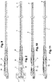
- the operation of the device can be illustrated by the positions occupied Figures 9,10 and 11 . So, in the position of the figure 9 the system is at rest, and the board is not flexed, and the central portion 63 of the rod 60 is in an intermediate position, so that no compression force is exerted on the viscoelastic material parts 10.20.
- the rod 3 moves so that its attachment point 8 gets closer 2.
- the rod pushes the rod 60 inside the housing 2.
- the central portion 63 of the rod 60 exerts a push on the viscoelastic material element 20 located at the bottom of the housing 2, compressing this element.
- the shear phenomena occurring during the compression and the deformation of this element 20 lead to the damping of the bending movement of the board.
- the materials and geometries of the viscoelastic material parts will be chosen accordingly. It is of course also possible to equip the housing with only one element of viscoelastic material, if one wishes to dampen the movements in only one direction. In general, and as already mentioned, it may be preferable primarily to dampen the flexion movements, the counter bending movements are in turn weakly or not amortized at all. In the latter case, the piece of viscoelastic material is then particularly rigid, and plays only a role of abutment, and could even be replaced by a rigid washer, thus reducing the bulk of the housing. In another variant embodiment, the pieces of viscoelastic material could be removable and interchangeable so that the user can choose the hardness of these parts depending on the behavior he seeks on the snow. In particular the transparent area could be in this case removable.
- the device according to the invention has multiple advantages, and in particular that of having a suitable stiffness and nonlinear chosen to obtain a board less disturbed by the irregularities of the ground, making the board easier to drive.
- the shape and material chosen for the piece of deformable viscoelastic material provide effective damping while occupying a reduced volume.
Landscapes
- Engineering & Computer Science (AREA)
- General Engineering & Computer Science (AREA)
- Mechanical Engineering (AREA)
- Vibration Dampers (AREA)
- Vibration Prevention Devices (AREA)
Claims (11)
- Dämpfervorrichtung (1), die dazu bestimmt ist, auf einem Gleitbrett montiert zu werden, mit einem beweglichen Element, das mit einem Mechanismus (3) zum Übertragen der Kräfte verbunden ist, die während der Verformung der Platte erzeugt werden, und mit einem Stück (10, 20) aus einem verformbares viskoelastisches Material, dadurch gekennzeichnet, dass dieses Stück (10, 20) eine Form hat, deren Querschnitt in der Querebene in Längsrichtung abwechselnd zunimmt und abnimmt, und dabei Vertiefungen und Stege bildet, der Abstand zwischen den Vertiefungen und/ oder der Abstand zwischen den Stegen ändert sich während der Verformung dieses Stücks und dadurch dass das Stück (10, 20) einen zentralen Kanal (25) umfasst, durch den ein Element (60) des Übertragungsmechanismus hindurchführt.
- Vorrichtung gemäß Anspruch 1, dadurch gekennzeichnet, dass das Stück (10, 20) aus viskoelastischem Material eine Drehform aufweist.
- Vorrichtung gemäß Anspruch 1, dadurch gekennzeichnet, dass das Stück (10, 20) aus viskoelastischem Material sich linear zwischen zwei Extrempunkten (16) ändert.
- Vorrichtung gemäß Anspruch 1, dadurch gekennzeichnet, dass das Stück (10, 20) aus viskoelastischem Material eine Shore- Härte zwischen 60 und 90 Shore A aufweist.
- Vorrichtung gemäß Anspruch 1, dadurch gekennzeichnet, dass es ein zweites Stück (10, 20) aus viskoelastischem Material enthält, dessen Härte sich von der Härte des ersten viskoelastischen Stücks (20, 10) unterscheidet.
- Vorrichtung gemäß Anspruch 1, dadurch gekennzeichnet, dass der Übertragungsmechanismus eine Stange (3) enthält, verbunden mit einem Kolben, der gegen eine Seite des Stücks (10, 20) aus viskoelastischem Material stößt.
- Vorrichtung gemäß Anspruch 6, dadurch gekennzeichnet, dass es ein Gehäuse (2) enthält, dass mindestens ein Stück (10, 20) aus viskoelastischem Material enthält.
- Vorrichtung gemäß Anspruch 7, dadurch gekennzeichnet, dass das Gehäuse (2) eine transparente Zone (58), lotrecht zum verformbaren Stück aus viskoelastischem Material, enthält.
- Gleitbrett mit einer Vorrichtung gemäß irgendeinem der vorstehenden Ansprüche, dadurch gekennzeichnet, dass das erste Stück (20) sich bei der Biegung des Gleitbretts verformt und das zweite Stück (10) sich bei der Gegenbiegung des Gleitbretts verformt.
- Gleitbrett mit einer Vorrichtung gemäß Anspruch 9, dadurch gekennzeichnet, dass das verformbare Stück (20) aus viskoelastischem Material, das sich bei der Biegung des Gleitbretts verformt, eine Härte aufweist, die geringer ist, als die des Stücks (10) aus viskoelastischem Material, das sich bei der Gegenbiegung des Gleitbretts verformt.
- Gleitbrett gemäß Anspruch 10, dadurch gekennzeichnet, dass das erste Stück (20) aus viskoelastischem Material, eine Härte zwischen 60 und 90 Shore A aufweist, am besten um 80 Shore A, und dass das zweite Stück (10) aus viskoelastischem Material eine Härte von über 60 Shore D aufweist.
Applications Claiming Priority (1)
| Application Number | Priority Date | Filing Date | Title |
|---|---|---|---|
| FR1570042A FR3041267B1 (fr) | 2015-09-21 | 2015-09-21 | Dispositif amortisseur destine a etre monte sur une planche de glisse sur neige |
Publications (2)
| Publication Number | Publication Date |
|---|---|
| EP3144038A1 EP3144038A1 (de) | 2017-03-22 |
| EP3144038B1 true EP3144038B1 (de) | 2019-01-02 |
Family
ID=55182467
Family Applications (1)
| Application Number | Title | Priority Date | Filing Date |
|---|---|---|---|
| EP16187420.1A Active EP3144038B1 (de) | 2015-09-21 | 2016-09-06 | Stossdämpfungsvorrichtung zur montage auf einem gleitbrett für schnee |
Country Status (3)
| Country | Link |
|---|---|
| US (1) | US10265604B2 (de) |
| EP (1) | EP3144038B1 (de) |
| FR (1) | FR3041267B1 (de) |
Families Citing this family (2)
| Publication number | Priority date | Publication date | Assignee | Title |
|---|---|---|---|---|
| US10286288B1 (en) * | 2015-12-29 | 2019-05-14 | Alpine Radius Control Technologies, LLC | Torsional stabilizer for skis |
| CN115068924B (zh) * | 2022-04-18 | 2025-06-24 | 东莞市思移力智能科技有限公司 | 一种改良型电动滑板结构 |
Family Cites Families (17)
| Publication number | Priority date | Publication date | Assignee | Title |
|---|---|---|---|---|
| US2258046A (en) * | 1940-05-24 | 1941-10-07 | Clement Manufacture Enregistre | Ski |
| FR1407710A (fr) | 1964-06-22 | 1965-08-06 | Ski à éléments amortisseurs agissant progressivement | |
| US3762070A (en) * | 1972-10-30 | 1973-10-02 | Gen Motors Corp | Spinal column simulator |
| CH671887A5 (de) * | 1982-03-25 | 1989-10-13 | Brosi Bettosini | |
| FR2688410B1 (fr) * | 1992-03-10 | 1994-05-06 | Rossignol Sa Skis | Dispositif pour le montage sur un ski d'une fixation de securite, comprenant une butee et une talonniere independantes l'une de l'autre. |
| FR2698012B1 (fr) * | 1992-11-19 | 1994-12-16 | Rossignol Sa | Structure de ski. |
| FR2709071B1 (fr) * | 1993-08-20 | 1995-10-27 | Salomon Sa | Ski perfectionné muni de dispositifs élastiques pour s'opposer et/ou amortir les sollicitations en flexion. |
| FR2720007B1 (fr) * | 1994-05-18 | 1996-07-12 | Salomon Sa | Ski alpin muni d'un dispositif de raidissement et/ou d'amortissement à double effet. |
| FR2734164B1 (fr) * | 1995-05-17 | 1997-06-13 | Rossignol Sa | Dispositif de rehaussement d'une fixation de ski, et ski equipe d'un tel dispositif |
| DE19517417A1 (de) * | 1995-05-17 | 1996-11-21 | Marker Deutschland Gmbh | Skibindung |
| FR2740982B1 (fr) * | 1995-11-10 | 1997-12-26 | Rossignol Sa | Planche de glisse sur neige |
| FR2741814B1 (fr) * | 1995-12-04 | 1998-02-13 | Salomon Sa | Dispositif d'amortissement pour planche de glisse |
| JPH1016527A (ja) * | 1996-07-05 | 1998-01-20 | Nissan Motor Co Ltd | 車両用サスペンション |
| FR2752743B1 (fr) * | 1996-08-29 | 1998-10-30 | Salomon Sa | Planche de surf de neige munie d'un dispositif d'amortissement |
| US6086101A (en) * | 1998-01-16 | 2000-07-11 | Cormican; Dale Dewayne | Adjustable flex ski apparatus |
| US20040178606A1 (en) * | 2003-03-11 | 2004-09-16 | Peter Ashley | Dynamic damping and stiffening system for sliding boards |
| FR2922779B1 (fr) * | 2007-10-25 | 2010-02-19 | Salomon Sa | Ensemble pour la pratique d'un sport de glisse ou de roulage |
-
2015
- 2015-09-21 FR FR1570042A patent/FR3041267B1/fr not_active Expired - Fee Related
-
2016
- 2016-09-06 EP EP16187420.1A patent/EP3144038B1/de active Active
- 2016-09-19 US US15/268,944 patent/US10265604B2/en not_active Expired - Fee Related
Non-Patent Citations (1)
| Title |
|---|
| None * |
Also Published As
| Publication number | Publication date |
|---|---|
| EP3144038A1 (de) | 2017-03-22 |
| US10265604B2 (en) | 2019-04-23 |
| FR3041267B1 (fr) | 2019-05-24 |
| US20170080324A1 (en) | 2017-03-23 |
| FR3041267A1 (fr) | 2017-03-24 |
Similar Documents
| Publication | Publication Date | Title |
|---|---|---|
| EP1563876B1 (de) | Langlaufski | |
| EP0560695B1 (de) | Vorrichtung enthaltend eine unabhängige Vorderbildung und Fersenhalter | |
| EP0409749A1 (de) | Zusatzvorrichtung zum Ski zur Montage eines Paares Skibindungen auf dem Ski | |
| FR2663234A1 (fr) | Support pour fixations de ski. | |
| FR2885589A1 (fr) | Dispositif de fixation d'une selle sur une tete de tige de selle | |
| EP3144038B1 (de) | Stossdämpfungsvorrichtung zur montage auf einem gleitbrett für schnee | |
| WO2013120763A1 (fr) | Butee d'amortissement pour articulation, notamment pour articulation de porte de vehicule | |
| EP2249724B1 (de) | Element zur dynamischen Stabilisierung von Wirbeln | |
| EP1977934B1 (de) | Puffer zum Schutz eines Elements beim Zusammentreffen mit einem anderen Element | |
| EP0738479B1 (de) | Schuh mit Vorlageeinstellung des Schaftes | |
| EP1656973B1 (de) | Vorrichtung zur Montage der Teile einer Sicherheitsbindung auf einem Ski | |
| WO1997010033A1 (fr) | Patin a roues en ligne | |
| EP2037847B1 (de) | Fussprothese | |
| EP1166669B1 (de) | Snowboardstiefel | |
| FR2655867A1 (fr) | Fixation de securite de ski alpin. | |
| EP1836934B1 (de) | Lagerungselement für Sprungrahmen oder Lattenrost, die mit Mitteln zur Stabilitätseinstellung versehen sind | |
| FR2800623A1 (fr) | Dispositif interface entre un ski et des elements de retenue d'une chaussure sur le ski et ski ainsi equipe | |
| EP0865806A1 (de) | Vorderbacken einer Sicherheitsskibindung | |
| EP0878217B1 (de) | Gleitplatte für eine Sicherheitsbindung | |
| FR2810893A1 (fr) | Dispositif interface entre un ski alpin et des elements de retenue de la chaussure sur le ski | |
| FR2796300A1 (fr) | Dispositif interface entre un ski et des elements de retenue de la chaussure sur le ski | |
| FR2815264A1 (fr) | Dispositif interface entre une chaussure et des elements de retenue de la chaussure sur un ski alpin | |
| FR2743726A1 (fr) | Ensemble de retenue pour retenir une chaussure sur un ski | |
| EP2465588A1 (de) | Montagevorrichtung auf einem Ski für die Elemente einer Sicherheitsskibindung | |
| FR2712503A1 (fr) | Dispositif de réglage d'un élément sur son support, notamment d'un élément de fixation sur une planche de glisse. |
Legal Events
| Date | Code | Title | Description |
|---|---|---|---|
| PUAI | Public reference made under article 153(3) epc to a published international application that has entered the european phase |
Free format text: ORIGINAL CODE: 0009012 |
|
| STAA | Information on the status of an ep patent application or granted ep patent |
Free format text: STATUS: THE APPLICATION HAS BEEN PUBLISHED |
|
| AK | Designated contracting states |
Kind code of ref document: A1 Designated state(s): AL AT BE BG CH CY CZ DE DK EE ES FI FR GB GR HR HU IE IS IT LI LT LU LV MC MK MT NL NO PL PT RO RS SE SI SK SM TR |
|
| AX | Request for extension of the european patent |
Extension state: BA ME |
|
| STAA | Information on the status of an ep patent application or granted ep patent |
Free format text: STATUS: REQUEST FOR EXAMINATION WAS MADE |
|
| 17P | Request for examination filed |
Effective date: 20170817 |
|
| RBV | Designated contracting states (corrected) |
Designated state(s): AL AT BE BG CH CY CZ DE DK EE ES FI FR GB GR HR HU IE IS IT LI LT LU LV MC MK MT NL NO PL PT RO RS SE SI SK SM TR |
|
| RIC1 | Information provided on ipc code assigned before grant |
Ipc: F16F 7/12 20060101ALI20180813BHEP Ipc: A63C 5/075 20060101ALI20180813BHEP Ipc: F16F 3/093 20060101ALI20180813BHEP Ipc: A63C 5/12 20060101AFI20180813BHEP Ipc: F16F 1/376 20060101ALI20180813BHEP |
|
| GRAP | Despatch of communication of intention to grant a patent |
Free format text: ORIGINAL CODE: EPIDOSNIGR1 |
|
| STAA | Information on the status of an ep patent application or granted ep patent |
Free format text: STATUS: GRANT OF PATENT IS INTENDED |
|
| INTG | Intention to grant announced |
Effective date: 20181016 |
|
| GRAS | Grant fee paid |
Free format text: ORIGINAL CODE: EPIDOSNIGR3 |
|
| GRAA | (expected) grant |
Free format text: ORIGINAL CODE: 0009210 |
|
| STAA | Information on the status of an ep patent application or granted ep patent |
Free format text: STATUS: THE PATENT HAS BEEN GRANTED |
|
| AK | Designated contracting states |
Kind code of ref document: B1 Designated state(s): AL AT BE BG CH CY CZ DE DK EE ES FI FR GB GR HR HU IE IS IT LI LT LU LV MC MK MT NL NO PL PT RO RS SE SI SK SM TR |
|
| REG | Reference to a national code |
Ref country code: GB Ref legal event code: FG4D Free format text: NOT ENGLISH |
|
| REG | Reference to a national code |
Ref country code: CH Ref legal event code: EP Ref country code: AT Ref legal event code: REF Ref document number: 1083646 Country of ref document: AT Kind code of ref document: T Effective date: 20190115 |
|
| REG | Reference to a national code |
Ref country code: DE Ref legal event code: R096 Ref document number: 602016008891 Country of ref document: DE |
|
| REG | Reference to a national code |
Ref country code: IE Ref legal event code: FG4D Free format text: LANGUAGE OF EP DOCUMENT: FRENCH |
|
| REG | Reference to a national code |
Ref country code: NL Ref legal event code: MP Effective date: 20190102 |
|
| REG | Reference to a national code |
Ref country code: LT Ref legal event code: MG4D |
|
| REG | Reference to a national code |
Ref country code: AT Ref legal event code: MK05 Ref document number: 1083646 Country of ref document: AT Kind code of ref document: T Effective date: 20190102 |
|
| PG25 | Lapsed in a contracting state [announced via postgrant information from national office to epo] |
Ref country code: NL Free format text: LAPSE BECAUSE OF FAILURE TO SUBMIT A TRANSLATION OF THE DESCRIPTION OR TO PAY THE FEE WITHIN THE PRESCRIBED TIME-LIMIT Effective date: 20190102 |
|
| PG25 | Lapsed in a contracting state [announced via postgrant information from national office to epo] |
Ref country code: PT Free format text: LAPSE BECAUSE OF FAILURE TO SUBMIT A TRANSLATION OF THE DESCRIPTION OR TO PAY THE FEE WITHIN THE PRESCRIBED TIME-LIMIT Effective date: 20190502 Ref country code: ES Free format text: LAPSE BECAUSE OF FAILURE TO SUBMIT A TRANSLATION OF THE DESCRIPTION OR TO PAY THE FEE WITHIN THE PRESCRIBED TIME-LIMIT Effective date: 20190102 Ref country code: SE Free format text: LAPSE BECAUSE OF FAILURE TO SUBMIT A TRANSLATION OF THE DESCRIPTION OR TO PAY THE FEE WITHIN THE PRESCRIBED TIME-LIMIT Effective date: 20190102 Ref country code: PL Free format text: LAPSE BECAUSE OF FAILURE TO SUBMIT A TRANSLATION OF THE DESCRIPTION OR TO PAY THE FEE WITHIN THE PRESCRIBED TIME-LIMIT Effective date: 20190102 Ref country code: FI Free format text: LAPSE BECAUSE OF FAILURE TO SUBMIT A TRANSLATION OF THE DESCRIPTION OR TO PAY THE FEE WITHIN THE PRESCRIBED TIME-LIMIT Effective date: 20190102 Ref country code: NO Free format text: LAPSE BECAUSE OF FAILURE TO SUBMIT A TRANSLATION OF THE DESCRIPTION OR TO PAY THE FEE WITHIN THE PRESCRIBED TIME-LIMIT Effective date: 20190402 Ref country code: LT Free format text: LAPSE BECAUSE OF FAILURE TO SUBMIT A TRANSLATION OF THE DESCRIPTION OR TO PAY THE FEE WITHIN THE PRESCRIBED TIME-LIMIT Effective date: 20190102 |
|
| PG25 | Lapsed in a contracting state [announced via postgrant information from national office to epo] |
Ref country code: BG Free format text: LAPSE BECAUSE OF FAILURE TO SUBMIT A TRANSLATION OF THE DESCRIPTION OR TO PAY THE FEE WITHIN THE PRESCRIBED TIME-LIMIT Effective date: 20190402 Ref country code: RS Free format text: LAPSE BECAUSE OF FAILURE TO SUBMIT A TRANSLATION OF THE DESCRIPTION OR TO PAY THE FEE WITHIN THE PRESCRIBED TIME-LIMIT Effective date: 20190102 Ref country code: LV Free format text: LAPSE BECAUSE OF FAILURE TO SUBMIT A TRANSLATION OF THE DESCRIPTION OR TO PAY THE FEE WITHIN THE PRESCRIBED TIME-LIMIT Effective date: 20190102 Ref country code: HR Free format text: LAPSE BECAUSE OF FAILURE TO SUBMIT A TRANSLATION OF THE DESCRIPTION OR TO PAY THE FEE WITHIN THE PRESCRIBED TIME-LIMIT Effective date: 20190102 Ref country code: IS Free format text: LAPSE BECAUSE OF FAILURE TO SUBMIT A TRANSLATION OF THE DESCRIPTION OR TO PAY THE FEE WITHIN THE PRESCRIBED TIME-LIMIT Effective date: 20190502 Ref country code: GR Free format text: LAPSE BECAUSE OF FAILURE TO SUBMIT A TRANSLATION OF THE DESCRIPTION OR TO PAY THE FEE WITHIN THE PRESCRIBED TIME-LIMIT Effective date: 20190403 |
|
| REG | Reference to a national code |
Ref country code: DE Ref legal event code: R097 Ref document number: 602016008891 Country of ref document: DE |
|
| PG25 | Lapsed in a contracting state [announced via postgrant information from national office to epo] |
Ref country code: IT Free format text: LAPSE BECAUSE OF FAILURE TO SUBMIT A TRANSLATION OF THE DESCRIPTION OR TO PAY THE FEE WITHIN THE PRESCRIBED TIME-LIMIT Effective date: 20190102 Ref country code: RO Free format text: LAPSE BECAUSE OF FAILURE TO SUBMIT A TRANSLATION OF THE DESCRIPTION OR TO PAY THE FEE WITHIN THE PRESCRIBED TIME-LIMIT Effective date: 20190102 Ref country code: SK Free format text: LAPSE BECAUSE OF FAILURE TO SUBMIT A TRANSLATION OF THE DESCRIPTION OR TO PAY THE FEE WITHIN THE PRESCRIBED TIME-LIMIT Effective date: 20190102 Ref country code: AL Free format text: LAPSE BECAUSE OF FAILURE TO SUBMIT A TRANSLATION OF THE DESCRIPTION OR TO PAY THE FEE WITHIN THE PRESCRIBED TIME-LIMIT Effective date: 20190102 Ref country code: DK Free format text: LAPSE BECAUSE OF FAILURE TO SUBMIT A TRANSLATION OF THE DESCRIPTION OR TO PAY THE FEE WITHIN THE PRESCRIBED TIME-LIMIT Effective date: 20190102 Ref country code: EE Free format text: LAPSE BECAUSE OF FAILURE TO SUBMIT A TRANSLATION OF THE DESCRIPTION OR TO PAY THE FEE WITHIN THE PRESCRIBED TIME-LIMIT Effective date: 20190102 Ref country code: AT Free format text: LAPSE BECAUSE OF FAILURE TO SUBMIT A TRANSLATION OF THE DESCRIPTION OR TO PAY THE FEE WITHIN THE PRESCRIBED TIME-LIMIT Effective date: 20190102 Ref country code: CZ Free format text: LAPSE BECAUSE OF FAILURE TO SUBMIT A TRANSLATION OF THE DESCRIPTION OR TO PAY THE FEE WITHIN THE PRESCRIBED TIME-LIMIT Effective date: 20190102 |
|
| PLBE | No opposition filed within time limit |
Free format text: ORIGINAL CODE: 0009261 |
|
| STAA | Information on the status of an ep patent application or granted ep patent |
Free format text: STATUS: NO OPPOSITION FILED WITHIN TIME LIMIT |
|
| PG25 | Lapsed in a contracting state [announced via postgrant information from national office to epo] |
Ref country code: SM Free format text: LAPSE BECAUSE OF FAILURE TO SUBMIT A TRANSLATION OF THE DESCRIPTION OR TO PAY THE FEE WITHIN THE PRESCRIBED TIME-LIMIT Effective date: 20190102 |
|
| 26N | No opposition filed |
Effective date: 20191003 |
|
| PG25 | Lapsed in a contracting state [announced via postgrant information from national office to epo] |
Ref country code: SI Free format text: LAPSE BECAUSE OF FAILURE TO SUBMIT A TRANSLATION OF THE DESCRIPTION OR TO PAY THE FEE WITHIN THE PRESCRIBED TIME-LIMIT Effective date: 20190102 |
|
| PG25 | Lapsed in a contracting state [announced via postgrant information from national office to epo] |
Ref country code: TR Free format text: LAPSE BECAUSE OF FAILURE TO SUBMIT A TRANSLATION OF THE DESCRIPTION OR TO PAY THE FEE WITHIN THE PRESCRIBED TIME-LIMIT Effective date: 20190102 |
|
| PG25 | Lapsed in a contracting state [announced via postgrant information from national office to epo] |
Ref country code: MC Free format text: LAPSE BECAUSE OF FAILURE TO SUBMIT A TRANSLATION OF THE DESCRIPTION OR TO PAY THE FEE WITHIN THE PRESCRIBED TIME-LIMIT Effective date: 20190102 |
|
| REG | Reference to a national code |
Ref country code: CH Ref legal event code: PL |
|
| PG25 | Lapsed in a contracting state [announced via postgrant information from national office to epo] |
Ref country code: LI Free format text: LAPSE BECAUSE OF NON-PAYMENT OF DUE FEES Effective date: 20190930 Ref country code: LU Free format text: LAPSE BECAUSE OF NON-PAYMENT OF DUE FEES Effective date: 20190906 Ref country code: IE Free format text: LAPSE BECAUSE OF NON-PAYMENT OF DUE FEES Effective date: 20190906 Ref country code: CH Free format text: LAPSE BECAUSE OF NON-PAYMENT OF DUE FEES Effective date: 20190930 |
|
| REG | Reference to a national code |
Ref country code: BE Ref legal event code: MM Effective date: 20190930 |
|
| PG25 | Lapsed in a contracting state [announced via postgrant information from national office to epo] |
Ref country code: BE Free format text: LAPSE BECAUSE OF NON-PAYMENT OF DUE FEES Effective date: 20190930 |
|
| GBPC | Gb: european patent ceased through non-payment of renewal fee |
Effective date: 20200906 |
|
| PG25 | Lapsed in a contracting state [announced via postgrant information from national office to epo] |
Ref country code: CY Free format text: LAPSE BECAUSE OF FAILURE TO SUBMIT A TRANSLATION OF THE DESCRIPTION OR TO PAY THE FEE WITHIN THE PRESCRIBED TIME-LIMIT Effective date: 20190102 |
|
| PG25 | Lapsed in a contracting state [announced via postgrant information from national office to epo] |
Ref country code: MT Free format text: LAPSE BECAUSE OF FAILURE TO SUBMIT A TRANSLATION OF THE DESCRIPTION OR TO PAY THE FEE WITHIN THE PRESCRIBED TIME-LIMIT Effective date: 20190102 Ref country code: HU Free format text: LAPSE BECAUSE OF FAILURE TO SUBMIT A TRANSLATION OF THE DESCRIPTION OR TO PAY THE FEE WITHIN THE PRESCRIBED TIME-LIMIT; INVALID AB INITIO Effective date: 20160906 |
|
| PG25 | Lapsed in a contracting state [announced via postgrant information from national office to epo] |
Ref country code: GB Free format text: LAPSE BECAUSE OF NON-PAYMENT OF DUE FEES Effective date: 20200906 |
|
| PG25 | Lapsed in a contracting state [announced via postgrant information from national office to epo] |
Ref country code: MK Free format text: LAPSE BECAUSE OF FAILURE TO SUBMIT A TRANSLATION OF THE DESCRIPTION OR TO PAY THE FEE WITHIN THE PRESCRIBED TIME-LIMIT Effective date: 20190102 |
|
| PGFP | Annual fee paid to national office [announced via postgrant information from national office to epo] |
Ref country code: DE Payment date: 20230911 Year of fee payment: 8 |
|
| REG | Reference to a national code |
Ref country code: DE Ref legal event code: R119 Ref document number: 602016008891 Country of ref document: DE |
|
| PG25 | Lapsed in a contracting state [announced via postgrant information from national office to epo] |
Ref country code: DE Free format text: LAPSE BECAUSE OF NON-PAYMENT OF DUE FEES Effective date: 20250401 |
|
| PGFP | Annual fee paid to national office [announced via postgrant information from national office to epo] |
Ref country code: FR Payment date: 20250929 Year of fee payment: 10 |