EP3144039A1 - Engin de transport, en particulier engin de sport - Google Patents
Engin de transport, en particulier engin de sport Download PDFInfo
- Publication number
- EP3144039A1 EP3144039A1 EP15405056.1A EP15405056A EP3144039A1 EP 3144039 A1 EP3144039 A1 EP 3144039A1 EP 15405056 A EP15405056 A EP 15405056A EP 3144039 A1 EP3144039 A1 EP 3144039A1
- Authority
- EP
- European Patent Office
- Prior art keywords
- locomotion
- joint
- shoe
- axis
- binding
- Prior art date
- Legal status (The legal status is an assumption and is not a legal conclusion. Google has not performed a legal analysis and makes no representation as to the accuracy of the status listed.)
- Granted
Links
- 230000033001 locomotion Effects 0.000 title claims abstract description 136
- 230000007246 mechanism Effects 0.000 claims abstract description 52
- 210000003423 ankle Anatomy 0.000 claims abstract description 5
- 210000003127 knee Anatomy 0.000 claims abstract description 4
- 210000002414 leg Anatomy 0.000 claims description 18
- 241000909536 Gobiesocidae Species 0.000 claims description 3
- 230000000903 blocking effect Effects 0.000 claims 1
- 210000001699 lower leg Anatomy 0.000 description 35
- 238000005096 rolling process Methods 0.000 description 21
- 210000002683 foot Anatomy 0.000 description 5
- 230000003203 everyday effect Effects 0.000 description 4
- 244000309466 calf Species 0.000 description 2
- 230000009191 jumping Effects 0.000 description 2
- 210000003789 metatarsus Anatomy 0.000 description 2
- 230000006641 stabilisation Effects 0.000 description 2
- 238000011105 stabilization Methods 0.000 description 2
- 230000007704 transition Effects 0.000 description 2
- 230000009194 climbing Effects 0.000 description 1
- 230000001419 dependent effect Effects 0.000 description 1
- 238000006073 displacement reaction Methods 0.000 description 1
- 230000000694 effects Effects 0.000 description 1
- 230000003137 locomotive effect Effects 0.000 description 1
- 239000000696 magnetic material Substances 0.000 description 1
- 210000001872 metatarsal bone Anatomy 0.000 description 1
- 238000000034 method Methods 0.000 description 1
- 210000002445 nipple Anatomy 0.000 description 1
- 230000002441 reversible effect Effects 0.000 description 1
- 239000011435 rock Substances 0.000 description 1
- 210000002303 tibia Anatomy 0.000 description 1
Images


Classifications
-
- A—HUMAN NECESSITIES
- A63—SPORTS; GAMES; AMUSEMENTS
- A63C—SKATES; SKIS; ROLLER SKATES; DESIGN OR LAYOUT OF COURTS, RINKS OR THE LIKE
- A63C17/00—Roller skates; Skate-boards
- A63C17/20—Roller skates; Skate-boards with fixable wheels permitting the skates to be used for walking
-
- A—HUMAN NECESSITIES
- A43—FOOTWEAR
- A43B—CHARACTERISTIC FEATURES OF FOOTWEAR; PARTS OF FOOTWEAR
- A43B5/00—Footwear for sporting purposes
- A43B5/16—Skating boots
- A43B5/1666—Skating boots characterised by the upper
-
- A—HUMAN NECESSITIES
- A63—SPORTS; GAMES; AMUSEMENTS
- A63C—SKATES; SKIS; ROLLER SKATES; DESIGN OR LAYOUT OF COURTS, RINKS OR THE LIKE
- A63C17/00—Roller skates; Skate-boards
- A63C17/0086—Roller skates adjustable in length to fit the size of the foot
-
- A—HUMAN NECESSITIES
- A63—SPORTS; GAMES; AMUSEMENTS
- A63C—SKATES; SKIS; ROLLER SKATES; DESIGN OR LAYOUT OF COURTS, RINKS OR THE LIKE
- A63C17/00—Roller skates; Skate-boards
- A63C17/02—Roller skates; Skate-boards with wheels arranged in two pairs
-
- A—HUMAN NECESSITIES
- A63—SPORTS; GAMES; AMUSEMENTS
- A63C—SKATES; SKIS; ROLLER SKATES; DESIGN OR LAYOUT OF COURTS, RINKS OR THE LIKE
- A63C17/00—Roller skates; Skate-boards
- A63C17/04—Roller skates; Skate-boards with wheels arranged otherwise than in two pairs
- A63C17/06—Roller skates; Skate-boards with wheels arranged otherwise than in two pairs single-track type
-
- A—HUMAN NECESSITIES
- A63—SPORTS; GAMES; AMUSEMENTS
- A63C—SKATES; SKIS; ROLLER SKATES; DESIGN OR LAYOUT OF COURTS, RINKS OR THE LIKE
- A63C17/00—Roller skates; Skate-boards
- A63C17/18—Roller skates; Skate-boards convertible into ice or snow-running skates
-
- A—HUMAN NECESSITIES
- A63—SPORTS; GAMES; AMUSEMENTS
- A63C—SKATES; SKIS; ROLLER SKATES; DESIGN OR LAYOUT OF COURTS, RINKS OR THE LIKE
- A63C17/00—Roller skates; Skate-boards
- A63C17/26—Roller skates; Skate-boards with special auxiliary arrangements, e.g. illuminating, marking, or push-off devices
- A63C17/262—Roller skates; Skate-boards with special auxiliary arrangements, e.g. illuminating, marking, or push-off devices with foot bindings or supports therefor
-
- A—HUMAN NECESSITIES
- A63—SPORTS; GAMES; AMUSEMENTS
- A63C—SKATES; SKIS; ROLLER SKATES; DESIGN OR LAYOUT OF COURTS, RINKS OR THE LIKE
- A63C17/00—Roller skates; Skate-boards
- A63C2017/0053—Roller skates; Skate-boards with foot plate quick release or shoe binding
-
- A—HUMAN NECESSITIES
- A63—SPORTS; GAMES; AMUSEMENTS
- A63C—SKATES; SKIS; ROLLER SKATES; DESIGN OR LAYOUT OF COURTS, RINKS OR THE LIKE
- A63C2203/00—Special features of skates, skis, roller-skates, snowboards and courts
- A63C2203/06—Special features of skates, skis, roller-skates, snowboards and courts enabling conversion into another device
-
- A—HUMAN NECESSITIES
- A63—SPORTS; GAMES; AMUSEMENTS
- A63C—SKATES; SKIS; ROLLER SKATES; DESIGN OR LAYOUT OF COURTS, RINKS OR THE LIKE
- A63C2203/00—Special features of skates, skis, roller-skates, snowboards and courts
- A63C2203/10—Special features of skates, skis, roller-skates, snowboards and courts enabling folding, collapsing
-
- A—HUMAN NECESSITIES
- A63—SPORTS; GAMES; AMUSEMENTS
- A63C—SKATES; SKIS; ROLLER SKATES; DESIGN OR LAYOUT OF COURTS, RINKS OR THE LIKE
- A63C2203/00—Special features of skates, skis, roller-skates, snowboards and courts
- A63C2203/42—Details of chassis of ice or roller skates, of decks of skateboards
-
- A—HUMAN NECESSITIES
- A63—SPORTS; GAMES; AMUSEMENTS
- A63C—SKATES; SKIS; ROLLER SKATES; DESIGN OR LAYOUT OF COURTS, RINKS OR THE LIKE
- A63C2203/00—Special features of skates, skis, roller-skates, snowboards and courts
- A63C2203/44—Storage or transportation means for ice or roller skates
Definitions
- the invention relates to a locomotion device, in particular a sports device, according to the preamble of claim 1, which is attachable to the leg and shoe of a person wearing and on the one hand for rolling, sliding, jumping or walking away by means of a suitable locomotion device, on the other hand, but also optionally free walking with the wearer's shoe allowed by repositioning the locomotion device.
- Locomotives in particular sports equipment, for rolling, sliding, bouncing or walking, which can be attached to the leg and normal road or sports shoe of a wearer, have long been known in the art. So describes about US 2002/0125658 A1 an inline skate which can be fastened by means of a binding device on the road or sports shoe of a wearer.
- the binding device consists of a soleplate plate with Fussspitzenkappe, a heel cup and a leg shell, which are connected by screw and rivet connection.
- the actual locomotion device is arranged on the underside of the sole plate, which has a total of four successively arranged rollers for this purpose.
- the binding device has a multiple harness with corresponding locking mechanisms, by means of which the binding device and thus the entire inline skate can be attached to the leg and shoe of the person wearing it.
- inline skates are mainly used in sports and leisure, but they can also be used as pure Vehicles are used in everyday life.
- inline skates are often used for locomotion in urban environments. However, they are not fully usable there;
- many obstacles such as stairs, steps, steep climbs, bumpy or soft surfaces make rolling on the inline skates impossible
- in certain public areas such as pedestrian areas, public transport or the like
- the use of inline skates mostly forbidden is.
- the inline skater is often forced to put on and take off the inline skates in order to move on the normal footwear if necessary.
- other sports equipment such as crampons, which sometimes have to be put on and taken off when hiking / climbing, for example, when the ground changes from ice and snow to smooth, hard rock.
- the rail system In the lowered position, in which the rolling device for rolling travel is located on the underside of the shoe, the rail system can be locked by means of a clamping screw.
- a disadvantage of this rail system is that the rolling device in the folded position to the side far surpasses and greatly restricts free walking. Tight places or passages can be difficult to pass with the on both sides of the lower leg protruding outward rolling devices.
- the object of the present invention is therefore, locomotion devices, in particular sports equipment, of the type described above - which are attachable to the leg and shoe of a person wearing and on the one hand for rolling, sliding, jumping or walking means of moving a corresponding locomotion device are formed, but on the other hand by selectively repositioning the locomotion device allow free walking with the shoe of the person wearing - to improve to the effect that a free walking despite still tethered locomotion device is unhindered possible.
- the locomotion device comprises a locomotion device, a binding device, by means of which the locomotion device can be attached to the lower leg and a person's shoe, and a pivot mechanism connecting the locomotion device to at least a part of the binding device for optionally positioning the locomotion device in a first position on the underside of the locomotion device Shoe and a means of locomotion not used second position in which a free walking on the bottom of the shoe is possible and in which the sports equipment is fixed in use exclusively on the lower leg.
- the locomotion device is characterized in that the locomotion device can be positioned in the second position on the calf-side rear side and / or the tibial-side front side of the lower leg.
- the locomotion device can be designed in such a way that it can be positioned as a component either on the calf-side rear side or on the leg-side front side of the lower leg.
- the locomotion device consists of several parts, in particular of a first and a second Part, so that a part, in particular the first part of the shin-side front of the lower leg and another part, in particular the second part on the calf-side rear side of the lower leg is positionable.
- the locomotion device can be positioned laterally on the inside of the lower leg in the second position.
- positioning the locomotion device at the previously described points of the calf, the tibia and / or the inner side of the lower leg in no way restricts or impedes the freedom of movement during normal walking with the street shoe or sports shoe.
- the risk is minimized that the locomotion device, when in the second position, may inadvertently collide with persons and objects.
- the freedom of movement for normal walking is also given because the sports equipment is mounted according to the invention in the second position exclusively on the lower leg, so that the area of the foot, especially below the ankle, is completely free to move.
- the locomotion device can therefore be positioned at the previously described points in the region below the knee and above the ankle. As a result, the freedom of movement for the person wearing is particularly large.
- the wearer's shoe is not part of the locomotion device or sports equipment, but to be seen separately. This is the "normal" everyday, street or sports shoe, the person used for normal walking, what the use of the inventive locomotion or sports equipment under mobility and Flexibility aspects are particularly distinguished. Compared to a Fortschuls- or sports equipment with integrated shoe or bootie eliminates the locomotion device according to the present invention, a complex change to a "normal" everyday, street or sports shoe, which would otherwise be carried separately as additional load.
- the pivoting mechanism may be designed such that the locomotion device is pivotably mounted on at least part of the binding device about at least a first axis and rotatable about at least a second axis.
- the use of at least two axes in combination with a pivoting and rotating movement advantageously permits a particularly simple and space-saving positioning of the locomotion device from the first to the second position, in particular to the calf-side rear side and / or the shinbone-side front side of the lower leg.
- the pivoting device comprises at least one pivoting support, the one end with at least a portion of the binding device, preferably with a fixable on the lower leg portion of the binding device, via a first, in particular about the first axis rotating Joint and other ends with the locomotion device via a second, in particular about the second axis rotating joint is connected.
- the pivoting support can, for example, laterally on the inner or outer side of the locomotion device between the binding device and the locomotion device, preferably in the area on the left and right at the level of the metatarsus, be arranged.
- the pivot support is designed as a substantially U-shaped pivot bracket.
- the base of the U-shaped pivot bracket is arranged in the region above the footrest on the binding device and that part of the pivot support forms, which has the first, in particular rotating about the first axis hinge.
- the two legs of the U-shaped pivot bracket extend in this embodiment - based on the first position of the locomotion device - from the base of the left and right sides in the sole region of the metatarsus.
- the end region of each of the two legs of the U-shaped swivel bracket can each have a second, in particular about the second axis rotating joint.
- the pivot arm not only via a first and a second joint, but via at least a first joint and / or at least a second joint, in particular via a first joint and a plurality of second joints or via a plurality of first joints and a second Joint or via a plurality of first joints and a plurality of second joints, is connected to the binding device or the locomotion device.
- the pivot support is not only one piece - as a U-shaped swivel bracket - is formed, but in several parts.
- a pivot support which has two individual pivot support elements, each corresponding to one of the legs of the U-shaped pivot bracket, each of the two pivot support elements each having an end with at least a portion of the binding means on a first, in particular around the first Axis rotating joint and other ends connected to the locomotion device via a second, in particular about the second axis rotating joint is.
- the pivoting mechanism may additionally be designed such that the locomotion device is pivotably mounted on at least part of the binding device about at least a third axis and rotatable about at least a fourth axis.
- the pivoting device may have at least one further pivoting carrier which has an end with at least one part of the binding device, preferably on a calf-side region of the binding device, via a third joint, in particular rotating about the third axis, and other ends with the locomotion device is connected via a fourth, in particular about the fourth axis rotating joint.
- pivot carrier which is connected via the first and second axis or the first and second joint with the binding device with the locomotion device, can of course be applied to the further pivot carrier, with the third and fourth axis and the third and fourth joint is connected to the binding device or the locomotion device to be transmitted in an analogous manner.
- At least part of the pivoting mechanism, in particular the third joint is displaceably arranged by means of a guide device on a part of the binding device, preferably on a calf-side or suture-side region of the binding device.
- at least part of the pivot mechanism, in particular, the fourth joint is arranged displaceably by means of a guide device on a part of the locomotion device.
- Such a guide device advantageously makes it possible to transfer the locomotion device from the first to the second position in a particularly space-saving manner, in particular in a single pivoting movement from the underside of the shoe, ie from the first position, over the heel area the second position on the calf-side back of the lower leg.
- the guide means may for example comprise a guide rod or a guide rail on which the third joint or the fourth joint is slidably disposed.
- the third or fourth joint can be guided in this way between a first position corresponding to the first position end position and a second position corresponding to the second end position slidably.
- elastic elements for example springs, can be provided on the guide device, in particular on the guide rail or the guide rod, which elastically dampen the guided movement of the third or fourth articulation in the region of the two end positions.
- locking means may be provided according to a further advantageous embodiment of the invention.
- These locking means may in particular magnetic holding means and / or latching counter-latching holding means and / or a locking means for releasably locking the pivoting mechanism in each one of the first position and the second position corresponding position include.
- the binding device can be formed in one piece. It is also conceivable that the binding device according to a further advantageous embodiment of the invention comprises several parts that are not necessarily directly related to each other. It is conceivable in particular that the binding device has a heel cap, a fuselage cap, a running board and / or a sometimes padded leg shell. In particular, it can be provided that the heel cap and the Fussspitzenkappe are set directly to the locomotion device, whereas the leg shell is connected only via the pivot mechanism with the locomotion device.
- the sports equipment may have a folding mechanism, which is adapted to transfer the Fussspitzenkappe from a closed position to an open position and back.
- the toe cap includes the toe of the shoe, so that the sports equipment is stably connected to the shoe in this area.
- the Fussspitzenkappe for example, about a rotation axis in the area of the tip of the foot, shoe / footrest can be pivoted forward over in the open position.
- the toe is no longer involved in the Fussspitzenkappe, so that the locomotion device can be pivoted freely in the second position.
- the Fussspitzenkappe is to be pivoted together with the locomotion device in the second position on the calf-side rear side of the lower leg to allow free walking with the shoe.
- the transfer of the Fussspitzenkappe from the closed position to the open position and back automatically takes place when transferring the locomotion device from the first position to the second position and back.
- the folding mechanism used for this purpose can be actuated via the pivoting mechanism.
- the folding mechanism for transferring the Fussspitzkappe from the closed position to the open position has a first and second push rod and a rotary member.
- the first push rod one end by means of a joint, in particular ball joint, on a part of the pivot mechanism, in particular on the pivot support, and other ends by means of a joint, in particular ball joint, be mounted on the rotary member.
- the second push rod is an end by means of a joint, in particular ball joint, on the rotary member and other ends by means of a joint, in particular ball joint, on the Fussspitzenkappe, in particular a pivot arm of the Fussspitzenkappe stored.
- the rotary element is rotatable, in particular about an aligned in the first position perpendicular to the shoe sole axis of rotation, mounted on the locomotion device.
- the heel cap can be moved out freely using an additional folding mechanism between a closed position in which the heel cap is connected to the heel region of the shoe in an open position, in the heel region of the shoe from the heel cap her feasible.
- the further folding mechanism is also actuated via the pivoting mechanism, in particular automatically when transferring the locomotion device from the first to the second position.
- the folding mechanism is actuated independently of the pivoting mechanism.
- the heel cup may consist of two sometimes shell-like heel cup elements, which in the closed position in the heel region laterally and / or on the rear of the shoe preferably bear in a clamping manner.
- the two heel-cap elements In order to release the heel area of the shoe in the open position, it can be provided that the two heel-cap elements open, for example, towards the side in the manner of a wing.
- the two heel counter elements may be spring loaded about one or more elastic elements.
- the transfer to the closed position can be effected, for example, by the weight of the wearer who counteracts the spring force of the elastic elements.
- the two heel counter elements may sometimes comprise lever elements that can be actuated with the sole of the shoe and drive the heel counter elements into the closed position.
- the binding device may comprise at least one attachment means for securing the sports equipment on the lower leg.
- the at least one attachment means may preferably comprise closure means, in particular a hook-and-loop fastener, a buckle closure, a clamp closure, a cord stopper or a tension closure.
- closure means in particular a hook-and-loop fastener, a buckle closure, a clamp closure, a cord stopper or a tension closure.
- a buckle closure can sometimes be provided a click buckle, a bridge buckle, a buckle, or a double clamp buckle.
- the attachment means may have a padding.
- the rollers may sometimes have the same or different widths. Particularly conceivable are rolls with a width of up to 8 cm. Furthermore, the means of transportation, in particular the rollers, may have a backstop.
- the pivot mechanism by hand and / or actuated by at least one actuator, in particular at least one spring-driven actuator, or at least one pneumatic actuator, in particular of a pressure cylinder, or at least one electromotive Actuator, in particular of a servomotor.
- the pivoting mechanism, in particular the actuator can be actuated remotely, for example via an electromagnetic transmitter / receiver device or a mechanical actuating cable, in particular a push-pull actuating cable.
- a pull tab such as in the heel area of the locomotion device, be provided to transfer the locomotion device from the first to the second position by pulling by hand, in particular with one or two fingers.
- the pivot mechanism and / or the folding mechanism and / or the further folding mechanism include a gear drive, a slotted guide, a cam guide and / or a belt drive.
- the length of the sports equipment in particular the length of the locomotion device and parts of the binding device, can be made variably adjustable in the direction of the shoe longitudinal extension to the length of the shoe.
- the locomotion device and the footboard can be constructed in two parts, wherein the two parts of the locomotion device and of the footboard can be arranged displaceable relative to one another at different distances via a displacement device.
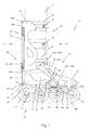
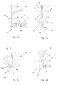
- Fig. 1 . 2a-2c and 3a-3d show a possible embodiment of an inventive locomotion device 1 using the example of an inline skate with up and downable rolling device.
- the locomotion device 1 comprises a locomotion device 10 with a total of four successively arranged roller means 11 and narrow rollers 11.
- the four rollers 11 are rotatably mounted in a common roller holder 12, which at the same time for connection to a part of a Binding device 20 is used.
- the locomotion device 1 can be attached to the lower leg 2 of a person wearing the sports device 1.
- the binding device 20 on the one hand, has a padded leg shell 23, which can be tied to the lower leg 2 with the aid of attachment means 24.
- the attachment means 24 have a plurality of pairs of belts or straps that close with a snap-buckle closure and can be opened.
- the binding device 20 comprises a heel cap 21, in which the heel region of the shoe 3 can be received for stabilization and attachment purposes, as well as a fuselage cap 22, in which the Fussspitzen Scheme of the shoe 3 can also be added for stabilization and connection purposes.
- the binding device 20 has a running board 24, on the upper side of which the underside 4 of the shoe 3 rests and on the underside of which the locomotion device 10 is fixed.
- the locomotion device 1 further comprises a swivel mechanism 30 which connects the locomotion device 10 and at least part of the binding device 20, in particular the padded leg shell 23, with the attachment means 24.
- the pivoting mechanism 30 serves to selectively dispose the traveling device 10 between a first position in which the locomotion device 10 is arranged on the underside 4 of the shoe 3 and a second position of the locomotion device 10 on the calf-side rear side 5 of the lower leg 2 position.
- the Fig. 1 . 2a-2c and 3a show the locomotion device 1 with the locomotion device 10 in the first position
- Fig. 3d shows the locomotion device 1 with the locomotion device 10 in the second position.
- the sports equipment 1 is attached in the second position exclusively on the lower leg 2 on the leg shell 23 and the attachment means 24 arranged thereon.
- this second position of the locomotion device 10 the area of the foot or the shoe 3, in particular below the ankle, completely free to move, so that a free walking on the bottom 4 of the shoe 3 despite the tethered sports equipment 1 on the lower leg 2 is easily possible.
- the positioning of the locomotion device 10 on the calf-side rear side 5 of the lower leg 2 restricts the freedom of movement during normal walking with the street shoe or sports shoe in any way. Also, the risk is significantly minimized that the locomotion device 10 may accidentally collide with persons and objects when it is located on the calf-side rear side 5 of the lower leg 2.
- the shoe 2 is a normal everyday, street or sports shoe, which is not part of the locomotion device 1, which particularly distinguishes the use of the inventive locomotion or sports device 1 from mobility and flexibility aspects.
- the pivoting mechanism 30 is formed according to the present embodiment such that the locomotion device 10 in the region above the clamping laterally to the left and right on the padded binding device 20 about a first axis 31a, 31b pivotable about at least one second axis 32a, 32b is rotatably mounted.
- the pivoting device a pivoting support, which in the present embodiment comprises a arranged on the left side of the shoe 3 pivot support member 33a and arranged on the right side of the shoe 3 pivot support member 33b.
- Each of the two pivoting carrier elements 33a, 33b is connected to one end of the left and right above the clamping region via a respective first and left hinge 131a, 131b rotating about the first axis 31a, 31b, respectively, to the binding device 20 with that part of the binding device 20 which can be fixed on the lower leg.
- each of the two pivoting carrier elements 33a, 33b is connected to the locomotion device 10 via a second pivot 132a, 132b rotating about the second axis 32a, 32b, namely to the left or right of the metatarsal region, respectively the inner or inner leg.
- the swiveling mechanism 30 is furthermore embodied such that the locomotion device 10 is pivotably mounted on a calf-side region of the binding device 20 about a third axis 34 and rotatably about a fourth axis 35.
- the pivoting mechanism 30 in addition to the pivot carrier 33a, 33b on another pivot support 36, which also has an end with a part of the binding device 20 via a third, about the third axis 34 rotating joint 134 and other ends with the locomotion device 10 via a fourth, about the fourth axis 35 rotating joint 135 is connected.
- this further pivot support 36 is in the form of a U-shaped bracket, wherein the third axis 34 extends parallel through the base of the U-shaped bracket and the fourth axis 35 is in the region of the two leg ends of the U-shaped bracket.
- the third joint 134 is additionally arranged by means of a guide device 37 slidably on a calf-side region of the binding device 20.
- the guide means 37 has for this purpose a guide rod 38, on which the third joint 134 is slidably disposed, between a first position corresponding first end position ( Fig. 3a ) and a second position corresponding to the second position ( Fig. 3d ).
- elastic elements in the present case springs, are provided on the guide rod 38 at the end.
- the sports equipment 1 further has a folding mechanism 40, which is designed to automatically transfer the fuselage cap 22 when transferring the locomotion device 10 from the first to the second position from a closed position to an open position.
- the folding mechanism 40 in the area of endeavorrists a first and second push rod 41, 42 and an angle-like rotary member 43.
- the first push rod 41 is mounted to one end by means of a ball joint 44 on the front left-side left pivot support 33 a and other ends by means of a ball joint 45 on the rotary member 43.
- the rotary member 43 is rotatably mounted on the locomotion device 10 about a rotation axis 43b, which - as in Fig.
- the folding mechanism 40 is actuated via the pivot mechanism 30 in the present embodiment. If the locomotion device 10 is transferred from the first to the second position with the aid of the pivoting mechanism 30, the pivotal movement of the pivoting carrier 33a causes the first pushrod 41 to be pressed laterally outwards, thereby rotating the rotary element 43 about the pivot 43b.
- the ball joint 46 arranged at a distance from the axis of rotation 43b is pulled rearwardly in the direction of the heel, as a result of which the swivel arm 22a is also pulled backwards by the push rod 42 and the foot tip cap 22 rotatably mounted about the rotation axis 22b is folded forward over.
- This unfolding of the nipple cap 22 is reversible when the locomotion device 10 is transferred back from the second to the first position.
- the locking means comprise on the one hand a magnetic holding means 39c above the guide rod 38, on which the further pivot carrier 36, which is preferably made of a magnetic material, is magnetically held in the second position on the calf-side rear side 5 of the binding device 20.
- a latching holding means 36a is provided on the further pivoting carrier 36, which engages in the second position with a corresponding counter-latching holding means 39b latchingly engaged.
- a locking means device (not shown here) is furthermore provided, by means of which the pivoting mechanism 30 can be releasably locked in the first position.
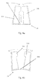
- the Fig. 4a and 4b show an exemplary embodiment of a further folding mechanism 24, which serves to open and close the heel counter 21.
- the two figures show the folding mechanism 24 in a front view with view from the shoe / foot tip towards the heel.
- the heel counter 21 consists of two individual shell-like heel counter elements 21a and 21b, which in the closed position (FIG. Fig. 4a ) in the heel area on the side and rear of the shoe clamped.
- Both heel counter elements 21a, 21b have lever elements 21c, 21d facing the underside of the shoe heel region or the heel, which are pressed down when the shoe heel is put on and thus drive the two heel counter elements 21a, 21b in a tilting movement into the closed position.
- a leaf spring 24a is provided on which the two heel counter elements 21a, 21b are arranged with their lever elements 21c, 21d and which counteracts the closed position.
- the spring force is chosen so that the weight of the wearer counteracts the placement of the shoe heel of the spring force of the leaf spring 24a.
Landscapes
- Health & Medical Sciences (AREA)
- General Health & Medical Sciences (AREA)
- Physical Education & Sports Medicine (AREA)
- Footwear And Its Accessory, Manufacturing Method And Apparatuses (AREA)
- Orthopedics, Nursing, And Contraception (AREA)
Priority Applications (2)
| Application Number | Priority Date | Filing Date | Title |
|---|---|---|---|
| EP15405056.1A EP3144039B1 (fr) | 2015-09-21 | 2015-09-21 | Engin de transport, en particulier engin de sport |
| PCT/EP2016/072174 WO2017050698A1 (fr) | 2015-09-21 | 2016-09-19 | Appareil de locomotion, en particulier appareil pour le sport |
Applications Claiming Priority (1)
| Application Number | Priority Date | Filing Date | Title |
|---|---|---|---|
| EP15405056.1A EP3144039B1 (fr) | 2015-09-21 | 2015-09-21 | Engin de transport, en particulier engin de sport |
Publications (2)
| Publication Number | Publication Date |
|---|---|
| EP3144039A1 true EP3144039A1 (fr) | 2017-03-22 |
| EP3144039B1 EP3144039B1 (fr) | 2019-03-27 |
Family
ID=54260708
Family Applications (1)
| Application Number | Title | Priority Date | Filing Date |
|---|---|---|---|
| EP15405056.1A Not-in-force EP3144039B1 (fr) | 2015-09-21 | 2015-09-21 | Engin de transport, en particulier engin de sport |
Country Status (2)
| Country | Link |
|---|---|
| EP (1) | EP3144039B1 (fr) |
| WO (1) | WO2017050698A1 (fr) |
Cited By (1)
| Publication number | Priority date | Publication date | Assignee | Title |
|---|---|---|---|---|
| US20180065029A1 (en) * | 2016-09-02 | 2018-03-08 | Dustin Dharma | Skates with a stowable and/or removable roller, blade, ski, or track assembly, and related methods of use |
Citations (6)
| Publication number | Priority date | Publication date | Assignee | Title |
|---|---|---|---|---|
| CH34817A (fr) * | 1905-07-11 | 1906-06-15 | Lucien Poncin Edouard | Patin à roulettes |
| DE19603712A1 (de) * | 1995-03-15 | 1997-08-14 | Gilbert Dr Duong | Vorrichtung zur Umwandlung eines Roll-bzw. Schlittschuhs in einen Gehschuh (Gehrollschuh bzw. Gehschlittschuh) |
| US5887898A (en) * | 1996-05-01 | 1999-03-30 | Petrosino; Chris | Skating/walking support |
| US20020125658A1 (en) | 2001-03-08 | 2002-09-12 | Ali Alwarid | In-line skate |
| CN2829812Y (zh) | 2005-10-31 | 2006-10-25 | 程满昌 | 可行走溜冰鞋 |
| DE202007011180U1 (de) * | 2007-08-10 | 2007-11-22 | Schroll, Stefan, Dipl.-Ing. (FH) | Inliner mit geteilter Radeinheit |
-
2015
- 2015-09-21 EP EP15405056.1A patent/EP3144039B1/fr not_active Not-in-force
-
2016
- 2016-09-19 WO PCT/EP2016/072174 patent/WO2017050698A1/fr not_active Ceased
Patent Citations (6)
| Publication number | Priority date | Publication date | Assignee | Title |
|---|---|---|---|---|
| CH34817A (fr) * | 1905-07-11 | 1906-06-15 | Lucien Poncin Edouard | Patin à roulettes |
| DE19603712A1 (de) * | 1995-03-15 | 1997-08-14 | Gilbert Dr Duong | Vorrichtung zur Umwandlung eines Roll-bzw. Schlittschuhs in einen Gehschuh (Gehrollschuh bzw. Gehschlittschuh) |
| US5887898A (en) * | 1996-05-01 | 1999-03-30 | Petrosino; Chris | Skating/walking support |
| US20020125658A1 (en) | 2001-03-08 | 2002-09-12 | Ali Alwarid | In-line skate |
| CN2829812Y (zh) | 2005-10-31 | 2006-10-25 | 程满昌 | 可行走溜冰鞋 |
| DE202007011180U1 (de) * | 2007-08-10 | 2007-11-22 | Schroll, Stefan, Dipl.-Ing. (FH) | Inliner mit geteilter Radeinheit |
Cited By (2)
| Publication number | Priority date | Publication date | Assignee | Title |
|---|---|---|---|---|
| US20180065029A1 (en) * | 2016-09-02 | 2018-03-08 | Dustin Dharma | Skates with a stowable and/or removable roller, blade, ski, or track assembly, and related methods of use |
| US10471336B2 (en) * | 2016-09-02 | 2019-11-12 | Dustin Dharma | Skates with a stowable and/or removable roller, blade, ski, or track assembly, and related methods of use |
Also Published As
| Publication number | Publication date |
|---|---|
| EP3144039B1 (fr) | 2019-03-27 |
| WO2017050698A1 (fr) | 2017-03-30 |
Similar Documents
| Publication | Publication Date | Title |
|---|---|---|
| DE69532497T2 (de) | Snowboardbindung | |
| DE2454976A1 (de) | Apparat zum imitierten skilaufen | |
| EP0167765B1 (fr) | Chaussure de ski | |
| EP0486013A1 (fr) | Appareil de sport | |
| DE69207262T2 (de) | Langlauf-Skischuh | |
| EP3144039B1 (fr) | Engin de transport, en particulier engin de sport | |
| EP3758812B1 (fr) | Fixation de snowboard en deux parties séparables | |
| DE102011016036A1 (de) | Skischuh, Ski und Skibindung | |
| DE102013100918B4 (de) | Modularer Skistiefel mit leicht entnehmbarem Innenschuh | |
| DE102012021808A1 (de) | Bremsvorrichtung für Skiroller oder Rollski | |
| DE19654899A1 (de) | Inline-Skater | |
| EP3197572A1 (fr) | Ski mixte pour la montée et la descente | |
| DE102012214002B4 (de) | Touring-Ferse mit Hilfshebel | |
| DE102004003040A1 (de) | Schnee-Eis-Schuh zum Gehen auf Schnee oder Eis | |
| WO1997038764A1 (fr) | Fixation de planche a neige | |
| DE19503792A1 (de) | Schlittschuhstiefel bzw. Rollschuhstiefel für Eis bzw. Rollhockey | |
| DE599013C (de) | Abnehmbare Skibindung mit zweiteiliger drehbarer Metallsohle | |
| EP3714951A1 (fr) | Fixation de ski | |
| DE202012001536U1 (de) | Schneeschuh | |
| EP2667953A2 (fr) | Ski mixte pour la montée et la descente | |
| AT412617B (de) | Einrichtung zum bremsen bei mit hilfe von stöcken betriebenen sportarten | |
| AT504900B1 (de) | Wintersportgerät | |
| WO1996024266A1 (fr) | Chaussure de patin a glace ou de patin a roulettes pour hockey sur glace ou a roulettes | |
| DE102021121984A1 (de) | Splitboardbindung | |
| AT516427B1 (de) | Bremsvorrichtung für Skiroller, Rollski oder Skier |
Legal Events
| Date | Code | Title | Description |
|---|---|---|---|
| PUAI | Public reference made under article 153(3) epc to a published international application that has entered the european phase |
Free format text: ORIGINAL CODE: 0009012 |
|
| STAA | Information on the status of an ep patent application or granted ep patent |
Free format text: STATUS: THE APPLICATION HAS BEEN PUBLISHED |
|
| AK | Designated contracting states |
Kind code of ref document: A1 Designated state(s): AL AT BE BG CH CY CZ DE DK EE ES FI FR GB GR HR HU IE IS IT LI LT LU LV MC MK MT NL NO PL PT RO RS SE SI SK SM TR |
|
| AX | Request for extension of the european patent |
Extension state: BA ME |
|
| STAA | Information on the status of an ep patent application or granted ep patent |
Free format text: STATUS: REQUEST FOR EXAMINATION WAS MADE |
|
| 17P | Request for examination filed |
Effective date: 20170913 |
|
| RBV | Designated contracting states (corrected) |
Designated state(s): AL AT BE BG CH CY CZ DE DK EE ES FI FR GB GR HR HU IE IS IT LI LT LU LV MC MK MT NL NO PL PT RO RS SE SI SK SM TR |
|
| GRAP | Despatch of communication of intention to grant a patent |
Free format text: ORIGINAL CODE: EPIDOSNIGR1 |
|
| STAA | Information on the status of an ep patent application or granted ep patent |
Free format text: STATUS: GRANT OF PATENT IS INTENDED |
|
| INTG | Intention to grant announced |
Effective date: 20181015 |
|
| GRAS | Grant fee paid |
Free format text: ORIGINAL CODE: EPIDOSNIGR3 |
|
| GRAA | (expected) grant |
Free format text: ORIGINAL CODE: 0009210 |
|
| STAA | Information on the status of an ep patent application or granted ep patent |
Free format text: STATUS: THE PATENT HAS BEEN GRANTED |
|
| AK | Designated contracting states |
Kind code of ref document: B1 Designated state(s): AL AT BE BG CH CY CZ DE DK EE ES FI FR GB GR HR HU IE IS IT LI LT LU LV MC MK MT NL NO PL PT RO RS SE SI SK SM TR |
|
| REG | Reference to a national code |
Ref country code: GB Ref legal event code: FG4D Free format text: NOT ENGLISH |
|
| REG | Reference to a national code |
Ref country code: CH Ref legal event code: EP |
|
| REG | Reference to a national code |
Ref country code: AT Ref legal event code: REF Ref document number: 1112346 Country of ref document: AT Kind code of ref document: T Effective date: 20190415 |
|
| REG | Reference to a national code |
Ref country code: IE Ref legal event code: FG4D Free format text: LANGUAGE OF EP DOCUMENT: GERMAN |
|
| REG | Reference to a national code |
Ref country code: DE Ref legal event code: R096 Ref document number: 502015008471 Country of ref document: DE |
|
| REG | Reference to a national code |
Ref country code: CH Ref legal event code: NV Representative=s name: R.A. EGLI AND CO, PATENTANWAELTE, CH |
|
| REG | Reference to a national code |
Ref country code: NL Ref legal event code: FP |
|
| PG25 | Lapsed in a contracting state [announced via postgrant information from national office to epo] |
Ref country code: LT Free format text: LAPSE BECAUSE OF FAILURE TO SUBMIT A TRANSLATION OF THE DESCRIPTION OR TO PAY THE FEE WITHIN THE PRESCRIBED TIME-LIMIT Effective date: 20190327 Ref country code: SE Free format text: LAPSE BECAUSE OF FAILURE TO SUBMIT A TRANSLATION OF THE DESCRIPTION OR TO PAY THE FEE WITHIN THE PRESCRIBED TIME-LIMIT Effective date: 20190327 Ref country code: NO Free format text: LAPSE BECAUSE OF FAILURE TO SUBMIT A TRANSLATION OF THE DESCRIPTION OR TO PAY THE FEE WITHIN THE PRESCRIBED TIME-LIMIT Effective date: 20190627 Ref country code: FI Free format text: LAPSE BECAUSE OF FAILURE TO SUBMIT A TRANSLATION OF THE DESCRIPTION OR TO PAY THE FEE WITHIN THE PRESCRIBED TIME-LIMIT Effective date: 20190327 |
|
| PG25 | Lapsed in a contracting state [announced via postgrant information from national office to epo] |
Ref country code: BG Free format text: LAPSE BECAUSE OF FAILURE TO SUBMIT A TRANSLATION OF THE DESCRIPTION OR TO PAY THE FEE WITHIN THE PRESCRIBED TIME-LIMIT Effective date: 20190627 Ref country code: HR Free format text: LAPSE BECAUSE OF FAILURE TO SUBMIT A TRANSLATION OF THE DESCRIPTION OR TO PAY THE FEE WITHIN THE PRESCRIBED TIME-LIMIT Effective date: 20190327 Ref country code: RS Free format text: LAPSE BECAUSE OF FAILURE TO SUBMIT A TRANSLATION OF THE DESCRIPTION OR TO PAY THE FEE WITHIN THE PRESCRIBED TIME-LIMIT Effective date: 20190327 Ref country code: LV Free format text: LAPSE BECAUSE OF FAILURE TO SUBMIT A TRANSLATION OF THE DESCRIPTION OR TO PAY THE FEE WITHIN THE PRESCRIBED TIME-LIMIT Effective date: 20190327 Ref country code: GR Free format text: LAPSE BECAUSE OF FAILURE TO SUBMIT A TRANSLATION OF THE DESCRIPTION OR TO PAY THE FEE WITHIN THE PRESCRIBED TIME-LIMIT Effective date: 20190628 |
|
| PG25 | Lapsed in a contracting state [announced via postgrant information from national office to epo] |
Ref country code: AL Free format text: LAPSE BECAUSE OF FAILURE TO SUBMIT A TRANSLATION OF THE DESCRIPTION OR TO PAY THE FEE WITHIN THE PRESCRIBED TIME-LIMIT Effective date: 20190327 Ref country code: ES Free format text: LAPSE BECAUSE OF FAILURE TO SUBMIT A TRANSLATION OF THE DESCRIPTION OR TO PAY THE FEE WITHIN THE PRESCRIBED TIME-LIMIT Effective date: 20190327 Ref country code: SK Free format text: LAPSE BECAUSE OF FAILURE TO SUBMIT A TRANSLATION OF THE DESCRIPTION OR TO PAY THE FEE WITHIN THE PRESCRIBED TIME-LIMIT Effective date: 20190327 Ref country code: PT Free format text: LAPSE BECAUSE OF FAILURE TO SUBMIT A TRANSLATION OF THE DESCRIPTION OR TO PAY THE FEE WITHIN THE PRESCRIBED TIME-LIMIT Effective date: 20190727 Ref country code: EE Free format text: LAPSE BECAUSE OF FAILURE TO SUBMIT A TRANSLATION OF THE DESCRIPTION OR TO PAY THE FEE WITHIN THE PRESCRIBED TIME-LIMIT Effective date: 20190327 Ref country code: IT Free format text: LAPSE BECAUSE OF FAILURE TO SUBMIT A TRANSLATION OF THE DESCRIPTION OR TO PAY THE FEE WITHIN THE PRESCRIBED TIME-LIMIT Effective date: 20190327 Ref country code: CZ Free format text: LAPSE BECAUSE OF FAILURE TO SUBMIT A TRANSLATION OF THE DESCRIPTION OR TO PAY THE FEE WITHIN THE PRESCRIBED TIME-LIMIT Effective date: 20190327 Ref country code: RO Free format text: LAPSE BECAUSE OF FAILURE TO SUBMIT A TRANSLATION OF THE DESCRIPTION OR TO PAY THE FEE WITHIN THE PRESCRIBED TIME-LIMIT Effective date: 20190327 |
|
| PG25 | Lapsed in a contracting state [announced via postgrant information from national office to epo] |
Ref country code: SM Free format text: LAPSE BECAUSE OF FAILURE TO SUBMIT A TRANSLATION OF THE DESCRIPTION OR TO PAY THE FEE WITHIN THE PRESCRIBED TIME-LIMIT Effective date: 20190327 Ref country code: PL Free format text: LAPSE BECAUSE OF FAILURE TO SUBMIT A TRANSLATION OF THE DESCRIPTION OR TO PAY THE FEE WITHIN THE PRESCRIBED TIME-LIMIT Effective date: 20190327 |
|
| PG25 | Lapsed in a contracting state [announced via postgrant information from national office to epo] |
Ref country code: IS Free format text: LAPSE BECAUSE OF FAILURE TO SUBMIT A TRANSLATION OF THE DESCRIPTION OR TO PAY THE FEE WITHIN THE PRESCRIBED TIME-LIMIT Effective date: 20190727 |
|
| REG | Reference to a national code |
Ref country code: DE Ref legal event code: R097 Ref document number: 502015008471 Country of ref document: DE |
|
| PG25 | Lapsed in a contracting state [announced via postgrant information from national office to epo] |
Ref country code: DK Free format text: LAPSE BECAUSE OF FAILURE TO SUBMIT A TRANSLATION OF THE DESCRIPTION OR TO PAY THE FEE WITHIN THE PRESCRIBED TIME-LIMIT Effective date: 20190327 |
|
| PLBE | No opposition filed within time limit |
Free format text: ORIGINAL CODE: 0009261 |
|
| STAA | Information on the status of an ep patent application or granted ep patent |
Free format text: STATUS: NO OPPOSITION FILED WITHIN TIME LIMIT |
|
| PG25 | Lapsed in a contracting state [announced via postgrant information from national office to epo] |
Ref country code: SI Free format text: LAPSE BECAUSE OF FAILURE TO SUBMIT A TRANSLATION OF THE DESCRIPTION OR TO PAY THE FEE WITHIN THE PRESCRIBED TIME-LIMIT Effective date: 20190327 |
|
| 26N | No opposition filed |
Effective date: 20200103 |
|
| PG25 | Lapsed in a contracting state [announced via postgrant information from national office to epo] |
Ref country code: TR Free format text: LAPSE BECAUSE OF FAILURE TO SUBMIT A TRANSLATION OF THE DESCRIPTION OR TO PAY THE FEE WITHIN THE PRESCRIBED TIME-LIMIT Effective date: 20190327 |
|
| PG25 | Lapsed in a contracting state [announced via postgrant information from national office to epo] |
Ref country code: MC Free format text: LAPSE BECAUSE OF FAILURE TO SUBMIT A TRANSLATION OF THE DESCRIPTION OR TO PAY THE FEE WITHIN THE PRESCRIBED TIME-LIMIT Effective date: 20190327 |
|
| PG25 | Lapsed in a contracting state [announced via postgrant information from national office to epo] |
Ref country code: LU Free format text: LAPSE BECAUSE OF NON-PAYMENT OF DUE FEES Effective date: 20190921 Ref country code: IE Free format text: LAPSE BECAUSE OF NON-PAYMENT OF DUE FEES Effective date: 20190921 |
|
| PGFP | Annual fee paid to national office [announced via postgrant information from national office to epo] |
Ref country code: GB Payment date: 20200921 Year of fee payment: 6 Ref country code: NL Payment date: 20200925 Year of fee payment: 6 Ref country code: FR Payment date: 20200914 Year of fee payment: 6 |
|
| PGFP | Annual fee paid to national office [announced via postgrant information from national office to epo] |
Ref country code: AT Payment date: 20200921 Year of fee payment: 6 Ref country code: BE Payment date: 20200925 Year of fee payment: 6 |
|
| PG25 | Lapsed in a contracting state [announced via postgrant information from national office to epo] |
Ref country code: CY Free format text: LAPSE BECAUSE OF FAILURE TO SUBMIT A TRANSLATION OF THE DESCRIPTION OR TO PAY THE FEE WITHIN THE PRESCRIBED TIME-LIMIT Effective date: 20190327 |
|
| PG25 | Lapsed in a contracting state [announced via postgrant information from national office to epo] |
Ref country code: HU Free format text: LAPSE BECAUSE OF FAILURE TO SUBMIT A TRANSLATION OF THE DESCRIPTION OR TO PAY THE FEE WITHIN THE PRESCRIBED TIME-LIMIT; INVALID AB INITIO Effective date: 20150921 Ref country code: MT Free format text: LAPSE BECAUSE OF FAILURE TO SUBMIT A TRANSLATION OF THE DESCRIPTION OR TO PAY THE FEE WITHIN THE PRESCRIBED TIME-LIMIT Effective date: 20190327 |
|
| PGFP | Annual fee paid to national office [announced via postgrant information from national office to epo] |
Ref country code: DE Payment date: 20210920 Year of fee payment: 7 |
|
| PGFP | Annual fee paid to national office [announced via postgrant information from national office to epo] |
Ref country code: CH Payment date: 20211222 Year of fee payment: 7 |
|
| REG | Reference to a national code |
Ref country code: NL Ref legal event code: MM Effective date: 20211001 |
|
| REG | Reference to a national code |
Ref country code: AT Ref legal event code: MM01 Ref document number: 1112346 Country of ref document: AT Kind code of ref document: T Effective date: 20210921 |
|
| REG | Reference to a national code |
Ref country code: BE Ref legal event code: MM Effective date: 20210930 |
|
| GBPC | Gb: european patent ceased through non-payment of renewal fee |
Effective date: 20210921 |
|
| PG25 | Lapsed in a contracting state [announced via postgrant information from national office to epo] |
Ref country code: NL Free format text: LAPSE BECAUSE OF NON-PAYMENT OF DUE FEES Effective date: 20211001 Ref country code: MK Free format text: LAPSE BECAUSE OF FAILURE TO SUBMIT A TRANSLATION OF THE DESCRIPTION OR TO PAY THE FEE WITHIN THE PRESCRIBED TIME-LIMIT Effective date: 20190327 |
|
| PG25 | Lapsed in a contracting state [announced via postgrant information from national office to epo] |
Ref country code: GB Free format text: LAPSE BECAUSE OF NON-PAYMENT OF DUE FEES Effective date: 20210921 Ref country code: FR Free format text: LAPSE BECAUSE OF NON-PAYMENT OF DUE FEES Effective date: 20210930 Ref country code: BE Free format text: LAPSE BECAUSE OF NON-PAYMENT OF DUE FEES Effective date: 20210930 |
|
| PG25 | Lapsed in a contracting state [announced via postgrant information from national office to epo] |
Ref country code: AT Free format text: LAPSE BECAUSE OF NON-PAYMENT OF DUE FEES Effective date: 20210921 |
|
| REG | Reference to a national code |
Ref country code: DE Ref legal event code: R119 Ref document number: 502015008471 Country of ref document: DE |
|
| REG | Reference to a national code |
Ref country code: CH Ref legal event code: PL |
|
| PG25 | Lapsed in a contracting state [announced via postgrant information from national office to epo] |
Ref country code: LI Free format text: LAPSE BECAUSE OF NON-PAYMENT OF DUE FEES Effective date: 20220930 Ref country code: DE Free format text: LAPSE BECAUSE OF NON-PAYMENT OF DUE FEES Effective date: 20230401 Ref country code: CH Free format text: LAPSE BECAUSE OF NON-PAYMENT OF DUE FEES Effective date: 20220930 |