EP3144099B1 - Insert pour perceuse - Google Patents
Insert pour perceuse Download PDFInfo
- Publication number
- EP3144099B1 EP3144099B1 EP16180545.2A EP16180545A EP3144099B1 EP 3144099 B1 EP3144099 B1 EP 3144099B1 EP 16180545 A EP16180545 A EP 16180545A EP 3144099 B1 EP3144099 B1 EP 3144099B1
- Authority
- EP
- European Patent Office
- Prior art keywords
- insert
- drilling machine
- air
- drill
- longitudinal axis
- Prior art date
- Legal status (The legal status is an assumption and is not a legal conclusion. Google has not performed a legal analysis and makes no representation as to the accuracy of the status listed.)
- Active
Links
- 238000005553 drilling Methods 0.000 title claims description 31
- 239000012530 fluid Substances 0.000 claims description 5
- 238000001816 cooling Methods 0.000 description 8
- 238000005520 cutting process Methods 0.000 description 3
- 239000000498 cooling water Substances 0.000 description 2
- 230000000694 effects Effects 0.000 description 2
- 238000000605 extraction Methods 0.000 description 2
- 230000001419 dependent effect Effects 0.000 description 1
- 239000010432 diamond Substances 0.000 description 1
- 239000000428 dust Substances 0.000 description 1
- 239000002184 metal Substances 0.000 description 1
- 238000000034 method Methods 0.000 description 1
- 238000013021 overheating Methods 0.000 description 1
- 239000011150 reinforced concrete Substances 0.000 description 1
- 125000006850 spacer group Chemical class 0.000 description 1
Images


Classifications
-
- B—PERFORMING OPERATIONS; TRANSPORTING
- B23—MACHINE TOOLS; METAL-WORKING NOT OTHERWISE PROVIDED FOR
- B23Q—DETAILS, COMPONENTS, OR ACCESSORIES FOR MACHINE TOOLS, e.g. ARRANGEMENTS FOR COPYING OR CONTROLLING; MACHINE TOOLS IN GENERAL CHARACTERISED BY THE CONSTRUCTION OF PARTICULAR DETAILS OR COMPONENTS; COMBINATIONS OR ASSOCIATIONS OF METAL-WORKING MACHINES, NOT DIRECTED TO A PARTICULAR RESULT
- B23Q11/00—Accessories fitted to machine tools for keeping tools or parts of the machine in good working condition or for cooling work; Safety devices specially combined with or arranged in, or specially adapted for use in connection with, machine tools
- B23Q11/0042—Devices for removing chips
- B23Q11/0046—Devices for removing chips by sucking
-
- B—PERFORMING OPERATIONS; TRANSPORTING
- B23—MACHINE TOOLS; METAL-WORKING NOT OTHERWISE PROVIDED FOR
- B23B—TURNING; BORING
- B23B45/00—Hand-held or like portable drilling machines, e.g. drill guns; Equipment therefor
- B23B45/003—Attachments
-
- B—PERFORMING OPERATIONS; TRANSPORTING
- B23—MACHINE TOOLS; METAL-WORKING NOT OTHERWISE PROVIDED FOR
- B23B—TURNING; BORING
- B23B51/00—Tools for drilling machines
- B23B51/04—Drills for trepanning
-
- B—PERFORMING OPERATIONS; TRANSPORTING
- B28—WORKING CEMENT, CLAY, OR STONE
- B28D—WORKING STONE OR STONE-LIKE MATERIALS
- B28D1/00—Working stone or stone-like materials, e.g. brick, concrete or glass, not provided for elsewhere; Machines, devices, tools therefor
- B28D1/02—Working stone or stone-like materials, e.g. brick, concrete or glass, not provided for elsewhere; Machines, devices, tools therefor by sawing
- B28D1/04—Working stone or stone-like materials, e.g. brick, concrete or glass, not provided for elsewhere; Machines, devices, tools therefor by sawing with circular or cylindrical saw-blades or saw-discs
- B28D1/041—Working stone or stone-like materials, e.g. brick, concrete or glass, not provided for elsewhere; Machines, devices, tools therefor by sawing with circular or cylindrical saw-blades or saw-discs with cylinder saws, e.g. trepanning; saw cylinders, e.g. having their cutting rim equipped with abrasive particles
-
- B—PERFORMING OPERATIONS; TRANSPORTING
- B28—WORKING CEMENT, CLAY, OR STONE
- B28D—WORKING STONE OR STONE-LIKE MATERIALS
- B28D7/00—Accessories specially adapted for use with machines or devices of the preceding groups
- B28D7/02—Accessories specially adapted for use with machines or devices of the preceding groups for removing or laying dust, e.g. by spraying liquids; for cooling work
-
- E—FIXED CONSTRUCTIONS
- E21—EARTH OR ROCK DRILLING; MINING
- E21B—EARTH OR ROCK DRILLING; OBTAINING OIL, GAS, WATER, SOLUBLE OR MELTABLE MATERIALS OR A SLURRY OF MINERALS FROM WELLS
- E21B25/00—Apparatus for obtaining or removing undisturbed cores, e.g. core barrels or core extractors
-
- B—PERFORMING OPERATIONS; TRANSPORTING
- B23—MACHINE TOOLS; METAL-WORKING NOT OTHERWISE PROVIDED FOR
- B23B—TURNING; BORING
- B23B2231/00—Details of chucks, toolholder shanks or tool shanks
- B23B2231/04—Adapters
-
- B—PERFORMING OPERATIONS; TRANSPORTING
- B23—MACHINE TOOLS; METAL-WORKING NOT OTHERWISE PROVIDED FOR
- B23B—TURNING; BORING
- B23B2251/00—Details of tools for drilling machines
- B23B2251/68—Drills with provision for suction
Definitions
- the invention relates to an insert for a drilling machine, comprising: a fastening means for fastening the insert to the drill, at least one air channel, which can be brought by attaching the insert to the drill in fluid communication with at least one air-conveying portion of the drill and at least one stop for a drill core or parts of a core.
- the invention further relates to a drill comprising an insert according to the invention. Hollow bits are used in particular for core drilling of reinforced concrete. For cooling this hollow drill, it may be provided to flow through this with cooling water. In some cases, eg when decommissioning nuclear power plants, when drilling in rooms with sensitive equipment (eg EDP), the use of cooling water is undesirable and may even be ruled out. In these cases, the hollow drills are used in the dry boring process.
- a suction device for example in the form of an industrial vacuum cleaner, connected, via which the drill hole is removed. At the same time it comes through the suction to a cooling effect, which prevents overheating of the drill bits arranged on the hollow drill.
- a suction device for example in the form of an industrial vacuum cleaner, connected, via which the drill hole is removed.
- a cooling effect which prevents overheating of the drill bits arranged on the hollow drill.
- the DE 29 13 501 A1 shows, for example, a hollow drill with a shaft, a fastener for attachment to a drill and several acted upon by a vacuum cleaner air ducts for the extraction of drilling dust.
- Another hollow drill goes out of the DE 38 41 871 A1 which is connectable with an intermediate piece.
- This spacer has a with a Vacuum source acted upon, central blind hole for the extraction of cuttings on.
- the object of the present invention is thus to modify the use of a drill such that such a closure of the suction opening in the drilling adapter through the core and thus a failure of the air cooling is no longer possible.
- Another object is to provide a drilling machine that takes advantage of the advantages over the prior art use advantage.
- the at least one air duct is connected to at least one air inlet opening for immediate uptake of Bohrabrieb, which occurs when using the drill with a hollow drill, wherein the at least one air inlet opening is aligned obliquely to the longitudinal axis of the insert so that there is always a gap over which air can be sucked out of the area of the hollow drill.
- the drill core completely closes the at least one air inlet opening with one of its end faces.
- the size of the gap depends on the inclination of the air inlet opening relative to the longitudinal axis of the insert.
- a straight line aligned with the at least one air inlet opening intersects the longitudinal axis of the insert, basically any angle greater than zero degrees is conceivable. In preferred embodiments, angles of substantially 60 ° or 90 ° are present.
- Embodiments of the insert of the present invention are also encompassed with at least one first air inlet opening and at least one second air inlet opening, a straight line aligned normal to the at least one first air inlet opening intersecting the longitudinal axis of the insert and a straight line normal to the at least one second air inlet opening skewed to the longitudinal axis of the insert is arranged.
- protection is also desired for a drilling machine having at least one air-conveying section, an insert according to the invention and a counter-fastening means corresponding to the fastening means of the insert.
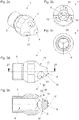
- FIG. 1a schematically shows a drill 4 with a arranged in a housing 23 drive unit, wherein the housing 23 has a handle portion 24.
- a drilling adapter 19 is arranged, which is detachably connected to the drill 4 connectable.
- an air-conducting portion 7 is formed, which is open on the one hand to a drill adapter 19 can be arranged on the hollow drill 21 and on the other hand is in fluid communication with a port 18 for a suction device.
- the suction device can be connected to the connection 18 via a suitable connecting means 25, for example a hose.
- a suitable connecting means 25 for example a hose.
- the drilling adapter 19 has a fastening means 20 for a hollow drill 21, for example in the form of an external thread. Alternatively, a bayonet closure or the like could be used. Via corresponding fastening means, e.g. an internal thread, a hollow drill 21 can be attached to the drilling adapter 19.
- the hollow drill 21 may have different diameters. Basically, they consist essentially of a hollow cylinder, on the frontal edge cutting segments 22 are arranged.
- the present invention provides to attach to the drill 4 an insert 1, the at least one air duct wherein, by the attachment of the insert 1 to the drill 4, the air channel in fluid communication with the air-conveying portion 7 of the drill 4 can be brought.
- the insert 1 has a stop for the drill core 11, and at least one air inlet opening with which the air duct is connected, wherein the air inlet opening is aligned obliquely to the longitudinal axis of the insert 1.
- FIGS. 2a to 2e show a first preferred embodiment of such an insert 1.
- the insert 1 has a cylindrical and a frusto-conical portion.
- a fastening means 5 is arranged in the form of an external thread, via which the insert 1 via a corresponding counter-fastening means 17 (see FIG. Figure 1c ) in the form of an internal thread with the drilling adapter 19 of the drill 4 is releasably connectable.
- an air channel 6 is formed (see, in particular FIG. 2e ).
- the air duct is partially coaxial with the longitudinal axis 12 of the insert 1.
- the air duct 6 is connected in the present case with three air inlet openings 13, which are aligned obliquely to the longitudinal axis 12 of the insert 1.
- a straight line 30 aligned with one of these air inlet openings 13 intersects the longitudinal axis 12 of the insert 1.
- the angle of intersection 29 in the present case is essentially 60 °.
- the insert 1 in a plan view of the stopper 8 (see. FIG. 2b ), it can be seen that the three air inlet openings 13 are arranged symmetrically about the longitudinal axis 12 of the insert 1.
- the offset 28 between two adjacent air inlet openings 13 is substantially 120 °.
- the stop 8 is formed substantially in the form of a surface, wherein the surface is aligned substantially normal to the longitudinal axis 12 of the insert 1. Furthermore, the stop 8 is formed on a carrier 14, wherein in this carrier 14 of the air duct 6, at least partially, is formed.
- the carrier 14 is formed in the present case substantially by the frusto-conical portion.
- the total length in the longitudinal direction 12 of the insert 1 is about 50 millimeters.
- FIG. 3 schematically a second particularly preferred embodiment of an insert 2 is shown.
- This insert 2 consists essentially of a cylindrical section, wherein at one end of this section a fastening means 5 for fastening the insert 2 to the drill 4 is formed.
- a stop 9 for a core 11 or parts of a core is arranged.
- the stopper 9 is substantially punctiform formed as a tip of a cone placed on the cylindrical portion. The cone may be formed integrally with the cylindrical portion.
- an air duct 6 Coaxially to the longitudinal axis 12 of the insert 2 extends inside the insert 2, an air duct 6 which is connected to an air inlet opening 13 which is aligned obliquely to the longitudinal axis 12 of the insert 2.
- a straight line which is oriented normal to the air inlet opening 13 and which extends into or out of the image plane intersects the longitudinal axis 12 of the insert 2. The angle of intersection is substantially 90 °.
- the cylindrical portion simultaneously constitutes a carrier 15 for the stop 9, wherein in the carrier, the air channel 6 is formed in regions.
- FIG. 4 shows schematically a third particularly preferred embodiment of an insert 3.
- the insert 3 also has a cylindrical portion, at one end of a fastening means 5 is provided for fastening the insert 3 to the drill 4.
- the opposite end is angled. In essence, it is an angled hollow cylinder.
- This has two air inlet openings 13, wherein one of the air inlet openings is formed on the end face of the hollow cylinder and a second air inlet opening 13 is formed on the lateral surface of the cylindrical portion.
- a straight line 30 aligned normal to the first air inlet opening 13 intersects the longitudinal axis 12 of the insert 3 at an angle 31 of substantially 90 °.
- a straight line aligned with the second air inlet opening 13 is aligned skewed to the longitudinal axis 12 of the insert 3.
- Both air inlet openings 13 are aligned in the sense of the invention obliquely to the longitudinal axis 12 of the insert 3, that is not normal to the longitudinal axis 12 of the insert.
- a core may strike the angled portion of the hollow cylinder. In this case, it is thus a stop 10, which is designed essentially as a straight line.
Landscapes
- Engineering & Computer Science (AREA)
- Mechanical Engineering (AREA)
- Mining & Mineral Resources (AREA)
- Life Sciences & Earth Sciences (AREA)
- Geology (AREA)
- Physics & Mathematics (AREA)
- Environmental & Geological Engineering (AREA)
- Fluid Mechanics (AREA)
- General Life Sciences & Earth Sciences (AREA)
- Geochemistry & Mineralogy (AREA)
- Processing Of Stones Or Stones Resemblance Materials (AREA)
- Drilling Tools (AREA)
Claims (12)
- Insert (1, 2, 3) pour une perceuse (4) avec : un moyen de fixation (5) pour fixer l'insert (1, 2, 3) sur la perceuse (4), au moins un canal d'air (6) qui, par la fixation de l'insert (1, 2, 3) sur la perceuse (4), peut être mis en relation fluide avec au moins une section conduisant l'air (7) de la perceuse (4) et au moins une butée (8, 9, 10) pour une carotte (11) ou des parties d'une carotte, dans lequel le au moins un canal d'air (6) est relié à au moins une ouverture d'entrée de l'air (13) pour l'absorption directe de l'usure d'abrasion, laquelle apparait lors de l'utilisation de la perceuse (4) avec une mèche creuse, caractérisé en ce que la au moins une ouverture d'entrée de l'air (13) est orientée obliquement à l'axe longitudinal (12) de l'insert (1, 2, 3), de sorte qu'une fente est toujours présente, par laquelle de l'air peut être aspiré depuis la zone de la mèche creuse.
- Insert (1, 2, 3) selon la revendication 1, dans lequel la au moins une butée (8, 9, 10) est conçue sur un support (14, 15, 16), dans lequel le au moins un canal d'air (6) est conçu au moins par endroits.
- Insert (1, 2, 3) selon la revendication 1 ou 2, dans lequel la au moins une butée (8, 9, 10) est conçue essentiellement en forme de point, comme une ligne droite ou comme une surface, de préférence dans lequel la surface est orientée essentiellement perpendiculairement à l'axe longitudinal (12) de l'insert (1, 2, 3).
- Insert (1, 2, 3) selon l'une des revendications 1 à 3, dans lequel l'insert (1, 2, 3) présente une section en cône tronqué et / ou une section cylindrique.
- Insert (1, 2, 3) selon l'une des revendications 1 à 4, dans lequel le au moins un canal d'air (6) est conçu au moins par endroits de façon coaxiale à l'axe longitudinal (12) de l'insert (1, 2, 3).
- Insert (1, 2, 3) selon l'une des revendications 1 à 5, dans lequel une ligne droite (30), orientée perpendiculairement à au moins une ouverture d'entrée d'air (13), coupe l'axe longitudinal (12) de l'insert (1, 2, 3) ou est disposée de façon inclinée par rapport à celui-ci.
- Insert (1, 2, 3) selon l'une des revendications 1 à 6, dans lequel le au moins un canal d'air (6) débouche dans trois ouvertures d'entrée d'air (13) disposées latéralement sur l'insert (1, 2, 3).
- Insert (1, 2, 3) selon l'une des revendications 1 à 7, dans lequel le moyen de fixation (5) destiné à fixer l'insert (1, 2, 3) sur la perceuse (4) est conçu comme un filetage.
- Perceuse (4) avec au moins une section conduisant l'air (7), un insert (1, 2, 3) selon l'une des revendications 1 à 8, et un moyen de contre-fixation (17) correspondant au moyen de fixation (5) de l'insert (1, 2, 3).
- Perceuse (4) selon la revendication 9, dans laquelle la au moins une section conduisant l'air (7) se trouve en relation fluide avec un raccordement (18) pour un dispositif d'aspiration.
- Perceuse (4) selon la revendication 9 ou 10, dans laquelle la au moins une section conduisant l'air (7) et le moyen de contre-fixation (17) sont conçus dans ou sur un adaptateur de forage (19) pouvant être relié de façon détachable de préférence à la perceuse (4).
- Perceuse (4) selon la revendication 11, dans laquelle un moyen de fixation (20) pour une mèche creuse (21) est conçu sur l'adaptateur de forage (19), de préférence en forme de filetage mâle.
Applications Claiming Priority (1)
| Application Number | Priority Date | Filing Date | Title |
|---|---|---|---|
| ATA50794/2015A AT517114B1 (de) | 2015-09-17 | 2015-09-17 | Einsatz für eine Bohrmaschine |
Publications (2)
| Publication Number | Publication Date |
|---|---|
| EP3144099A1 EP3144099A1 (fr) | 2017-03-22 |
| EP3144099B1 true EP3144099B1 (fr) | 2018-09-12 |
Family
ID=56507460
Family Applications (1)
| Application Number | Title | Priority Date | Filing Date |
|---|---|---|---|
| EP16180545.2A Active EP3144099B1 (fr) | 2015-09-17 | 2016-07-21 | Insert pour perceuse |
Country Status (4)
| Country | Link |
|---|---|
| EP (1) | EP3144099B1 (fr) |
| AT (1) | AT517114B1 (fr) |
| DE (1) | DE202016008579U1 (fr) |
| ES (1) | ES2701923T3 (fr) |
Cited By (2)
| Publication number | Priority date | Publication date | Assignee | Title |
|---|---|---|---|---|
| EP4201587A1 (fr) * | 2021-12-23 | 2023-06-28 | HILTI Aktiengesellschaft | Dispositif d'extraction de poussière pour une mèche d'outil |
| EP4371685A1 (fr) | 2022-11-17 | 2024-05-22 | Tyrolit - Schleifmittelwerke Swarovski AG & Co K.G. | Ensemble comprenant au moins une couronne de perçage et au moins une butée |
Families Citing this family (1)
| Publication number | Priority date | Publication date | Assignee | Title |
|---|---|---|---|---|
| EP4201586A1 (fr) * | 2021-12-23 | 2023-06-28 | HILTI Aktiengesellschaft | Mèche d'outil comportant un dispositif d'extraction de poussière |
Family Cites Families (2)
| Publication number | Priority date | Publication date | Assignee | Title |
|---|---|---|---|---|
| DE2913501A1 (de) * | 1979-04-04 | 1980-10-16 | Bosch Gmbh Robert | Hohlbohrer mit bohrkrone |
| DE3841871A1 (de) * | 1988-12-13 | 1990-06-21 | Biedron Bsb | Verfahren zum bohren von loechern in mauerwerk oder beton |
-
2015
- 2015-09-17 AT ATA50794/2015A patent/AT517114B1/de not_active IP Right Cessation
-
2016
- 2016-07-21 DE DE202016008579.5U patent/DE202016008579U1/de not_active Expired - Lifetime
- 2016-07-21 ES ES16180545T patent/ES2701923T3/es active Active
- 2016-07-21 EP EP16180545.2A patent/EP3144099B1/fr active Active
Non-Patent Citations (1)
| Title |
|---|
| None * |
Cited By (3)
| Publication number | Priority date | Publication date | Assignee | Title |
|---|---|---|---|---|
| EP4201587A1 (fr) * | 2021-12-23 | 2023-06-28 | HILTI Aktiengesellschaft | Dispositif d'extraction de poussière pour une mèche d'outil |
| WO2023118148A1 (fr) * | 2021-12-23 | 2023-06-29 | Hilti Aktiengesellschaft | Dispositif d'extraction de poussière pour outil rapporté |
| EP4371685A1 (fr) | 2022-11-17 | 2024-05-22 | Tyrolit - Schleifmittelwerke Swarovski AG & Co K.G. | Ensemble comprenant au moins une couronne de perçage et au moins une butée |
Also Published As
| Publication number | Publication date |
|---|---|
| EP3144099A1 (fr) | 2017-03-22 |
| AT517114A4 (de) | 2016-11-15 |
| AT517114B1 (de) | 2016-11-15 |
| ES2701923T3 (es) | 2019-02-26 |
| DE202016008579U1 (de) | 2018-07-11 |
Similar Documents
| Publication | Publication Date | Title |
|---|---|---|
| DE102015105047B4 (de) | Reduziermuffe mit Kühlmitteldurchfluss und eine Schneidevorrichtung, die eine solche Reduziermuffe verwendet | |
| EP2830799B1 (fr) | Foret de perçage | |
| DE60131780T2 (de) | Werkzeug und senker für spanabhebendes arbeiten | |
| EP0586423B1 (fr) | Outil de percage | |
| WO2012130857A1 (fr) | Outil d'usinage d'une pièce par enlèvement de copeaux, avec sortie latérale d'agent de refroidissement | |
| DE4032176C2 (de) | Scheibenschneider | |
| WO2014096359A1 (fr) | Segment de coupe pour une couronne de forage | |
| WO1990012193A1 (fr) | Raccord pour perçeuse a aspirateur | |
| DE102006028373A1 (de) | Trennstelle zwischen zwei Teilelementen eines drehenden Werkzeugsystems | |
| EP2848341A1 (fr) | Système d'outil destiné à la fabrication de trous de forage dans des matériaux tels que des matériaux composites renforcés par des fibres | |
| EP3144099B1 (fr) | Insert pour perceuse | |
| WO2018050267A1 (fr) | Tête de forage et outil de forage | |
| EP3656494B1 (fr) | Foret étagé | |
| DE202004011571U1 (de) | Werkzeugadapter | |
| EP3016770B1 (fr) | Système de tête interchangeable pour l'usinage de métaux | |
| EP3626213A1 (fr) | Instrument chirurgical, dispositif chirurgical et dispositif de commande électronique | |
| DE19710996A1 (de) | Bohrwerkzeug und Schneideinsätze für Bohrungen i Vollmaterial und zum Aufbohren | |
| DE10318091A1 (de) | Flachmeißel | |
| AT14973U1 (de) | Einsatz für eine Bohrmaschine | |
| DE102019111843A1 (de) | Zerspanungswerkzeug | |
| DE202013101404U1 (de) | Bohrwerkzeug | |
| EP2915613A1 (fr) | Foret à trou transversal | |
| EP3036058B1 (fr) | Dispositif et procédé d'ébavurage de tubes | |
| AT526727B1 (de) | Anordnung aus wenigstens einer Bohrkrone und wenigstens einem Anschlag | |
| DE19710997A1 (de) | Bohrwerkzeug und Schneideinsätze für Bohrungen in Vollmaterial und zum Aufbohren |
Legal Events
| Date | Code | Title | Description |
|---|---|---|---|
| REG | Reference to a national code |
Ref country code: DE Ref legal event code: R138 Ref document number: 202016008579 Country of ref document: DE Free format text: GERMAN DOCUMENT NUMBER IS 502016001926 |
|
| PUAI | Public reference made under article 153(3) epc to a published international application that has entered the european phase |
Free format text: ORIGINAL CODE: 0009012 |
|
| STAA | Information on the status of an ep patent application or granted ep patent |
Free format text: STATUS: THE APPLICATION HAS BEEN PUBLISHED |
|
| AK | Designated contracting states |
Kind code of ref document: A1 Designated state(s): AL AT BE BG CH CY CZ DE DK EE ES FI FR GB GR HR HU IE IS IT LI LT LU LV MC MK MT NL NO PL PT RO RS SE SI SK SM TR |
|
| AX | Request for extension of the european patent |
Extension state: BA ME |
|
| STAA | Information on the status of an ep patent application or granted ep patent |
Free format text: STATUS: REQUEST FOR EXAMINATION WAS MADE |
|
| 17P | Request for examination filed |
Effective date: 20170322 |
|
| RBV | Designated contracting states (corrected) |
Designated state(s): AL AT BE BG CH CY CZ DE DK EE ES FI FR GB GR HR HU IE IS IT LI LT LU LV MC MK MT NL NO PL PT RO RS SE SI SK SM TR |
|
| STAA | Information on the status of an ep patent application or granted ep patent |
Free format text: STATUS: EXAMINATION IS IN PROGRESS |
|
| 17Q | First examination report despatched |
Effective date: 20171006 |
|
| GRAP | Despatch of communication of intention to grant a patent |
Free format text: ORIGINAL CODE: EPIDOSNIGR1 |
|
| STAA | Information on the status of an ep patent application or granted ep patent |
Free format text: STATUS: GRANT OF PATENT IS INTENDED |
|
| INTG | Intention to grant announced |
Effective date: 20180409 |
|
| GRAS | Grant fee paid |
Free format text: ORIGINAL CODE: EPIDOSNIGR3 |
|
| GRAA | (expected) grant |
Free format text: ORIGINAL CODE: 0009210 |
|
| STAA | Information on the status of an ep patent application or granted ep patent |
Free format text: STATUS: THE PATENT HAS BEEN GRANTED |
|
| AK | Designated contracting states |
Kind code of ref document: B1 Designated state(s): AL AT BE BG CH CY CZ DE DK EE ES FI FR GB GR HR HU IE IS IT LI LT LU LV MC MK MT NL NO PL PT RO RS SE SI SK SM TR |
|
| REG | Reference to a national code |
Ref country code: GB Ref legal event code: FG4D Free format text: NOT ENGLISH |
|
| REG | Reference to a national code |
Ref country code: CH Ref legal event code: EP |
|
| REG | Reference to a national code |
Ref country code: IE Ref legal event code: FG4D Free format text: LANGUAGE OF EP DOCUMENT: GERMAN |
|
| REG | Reference to a national code |
Ref country code: DE Ref legal event code: R096 Ref document number: 502016001926 Country of ref document: DE |
|
| REG | Reference to a national code |
Ref country code: AT Ref legal event code: REF Ref document number: 1039981 Country of ref document: AT Kind code of ref document: T Effective date: 20181015 |
|
| REG | Reference to a national code |
Ref country code: CH Ref legal event code: NV Representative=s name: ISLER AND PEDRAZZINI AG, CH |
|
| REG | Reference to a national code |
Ref country code: NL Ref legal event code: FP |
|
| REG | Reference to a national code |
Ref country code: LT Ref legal event code: MG4D |
|
| REG | Reference to a national code |
Ref country code: NO Ref legal event code: T2 Effective date: 20180912 |
|
| REG | Reference to a national code |
Ref country code: SE Ref legal event code: TRGR |
|
| PG25 | Lapsed in a contracting state [announced via postgrant information from national office to epo] |
Ref country code: LT Free format text: LAPSE BECAUSE OF FAILURE TO SUBMIT A TRANSLATION OF THE DESCRIPTION OR TO PAY THE FEE WITHIN THE PRESCRIBED TIME-LIMIT Effective date: 20180912 Ref country code: FI Free format text: LAPSE BECAUSE OF FAILURE TO SUBMIT A TRANSLATION OF THE DESCRIPTION OR TO PAY THE FEE WITHIN THE PRESCRIBED TIME-LIMIT Effective date: 20180912 Ref country code: RS Free format text: LAPSE BECAUSE OF FAILURE TO SUBMIT A TRANSLATION OF THE DESCRIPTION OR TO PAY THE FEE WITHIN THE PRESCRIBED TIME-LIMIT Effective date: 20180912 Ref country code: BG Free format text: LAPSE BECAUSE OF FAILURE TO SUBMIT A TRANSLATION OF THE DESCRIPTION OR TO PAY THE FEE WITHIN THE PRESCRIBED TIME-LIMIT Effective date: 20181212 Ref country code: GR Free format text: LAPSE BECAUSE OF FAILURE TO SUBMIT A TRANSLATION OF THE DESCRIPTION OR TO PAY THE FEE WITHIN THE PRESCRIBED TIME-LIMIT Effective date: 20181213 |
|
| REG | Reference to a national code |
Ref country code: ES Ref legal event code: FG2A Ref document number: 2701923 Country of ref document: ES Kind code of ref document: T3 Effective date: 20190226 |
|
| PG25 | Lapsed in a contracting state [announced via postgrant information from national office to epo] |
Ref country code: AL Free format text: LAPSE BECAUSE OF FAILURE TO SUBMIT A TRANSLATION OF THE DESCRIPTION OR TO PAY THE FEE WITHIN THE PRESCRIBED TIME-LIMIT Effective date: 20180912 Ref country code: LV Free format text: LAPSE BECAUSE OF FAILURE TO SUBMIT A TRANSLATION OF THE DESCRIPTION OR TO PAY THE FEE WITHIN THE PRESCRIBED TIME-LIMIT Effective date: 20180912 Ref country code: HR Free format text: LAPSE BECAUSE OF FAILURE TO SUBMIT A TRANSLATION OF THE DESCRIPTION OR TO PAY THE FEE WITHIN THE PRESCRIBED TIME-LIMIT Effective date: 20180912 |
|
| PG25 | Lapsed in a contracting state [announced via postgrant information from national office to epo] |
Ref country code: CZ Free format text: LAPSE BECAUSE OF FAILURE TO SUBMIT A TRANSLATION OF THE DESCRIPTION OR TO PAY THE FEE WITHIN THE PRESCRIBED TIME-LIMIT Effective date: 20180912 Ref country code: IS Free format text: LAPSE BECAUSE OF FAILURE TO SUBMIT A TRANSLATION OF THE DESCRIPTION OR TO PAY THE FEE WITHIN THE PRESCRIBED TIME-LIMIT Effective date: 20190112 Ref country code: PL Free format text: LAPSE BECAUSE OF FAILURE TO SUBMIT A TRANSLATION OF THE DESCRIPTION OR TO PAY THE FEE WITHIN THE PRESCRIBED TIME-LIMIT Effective date: 20180912 Ref country code: EE Free format text: LAPSE BECAUSE OF FAILURE TO SUBMIT A TRANSLATION OF THE DESCRIPTION OR TO PAY THE FEE WITHIN THE PRESCRIBED TIME-LIMIT Effective date: 20180912 Ref country code: RO Free format text: LAPSE BECAUSE OF FAILURE TO SUBMIT A TRANSLATION OF THE DESCRIPTION OR TO PAY THE FEE WITHIN THE PRESCRIBED TIME-LIMIT Effective date: 20180912 |
|
| PG25 | Lapsed in a contracting state [announced via postgrant information from national office to epo] |
Ref country code: SM Free format text: LAPSE BECAUSE OF FAILURE TO SUBMIT A TRANSLATION OF THE DESCRIPTION OR TO PAY THE FEE WITHIN THE PRESCRIBED TIME-LIMIT Effective date: 20180912 Ref country code: SK Free format text: LAPSE BECAUSE OF FAILURE TO SUBMIT A TRANSLATION OF THE DESCRIPTION OR TO PAY THE FEE WITHIN THE PRESCRIBED TIME-LIMIT Effective date: 20180912 Ref country code: PT Free format text: LAPSE BECAUSE OF FAILURE TO SUBMIT A TRANSLATION OF THE DESCRIPTION OR TO PAY THE FEE WITHIN THE PRESCRIBED TIME-LIMIT Effective date: 20190112 |
|
| REG | Reference to a national code |
Ref country code: DE Ref legal event code: R097 Ref document number: 502016001926 Country of ref document: DE |
|
| PLBE | No opposition filed within time limit |
Free format text: ORIGINAL CODE: 0009261 |
|
| STAA | Information on the status of an ep patent application or granted ep patent |
Free format text: STATUS: NO OPPOSITION FILED WITHIN TIME LIMIT |
|
| PG25 | Lapsed in a contracting state [announced via postgrant information from national office to epo] |
Ref country code: DK Free format text: LAPSE BECAUSE OF FAILURE TO SUBMIT A TRANSLATION OF THE DESCRIPTION OR TO PAY THE FEE WITHIN THE PRESCRIBED TIME-LIMIT Effective date: 20180912 |
|
| 26N | No opposition filed |
Effective date: 20190613 |
|
| PG25 | Lapsed in a contracting state [announced via postgrant information from national office to epo] |
Ref country code: SI Free format text: LAPSE BECAUSE OF FAILURE TO SUBMIT A TRANSLATION OF THE DESCRIPTION OR TO PAY THE FEE WITHIN THE PRESCRIBED TIME-LIMIT Effective date: 20180912 |
|
| PG25 | Lapsed in a contracting state [announced via postgrant information from national office to epo] |
Ref country code: MC Free format text: LAPSE BECAUSE OF FAILURE TO SUBMIT A TRANSLATION OF THE DESCRIPTION OR TO PAY THE FEE WITHIN THE PRESCRIBED TIME-LIMIT Effective date: 20180912 |
|
| PG25 | Lapsed in a contracting state [announced via postgrant information from national office to epo] |
Ref country code: TR Free format text: LAPSE BECAUSE OF FAILURE TO SUBMIT A TRANSLATION OF THE DESCRIPTION OR TO PAY THE FEE WITHIN THE PRESCRIBED TIME-LIMIT Effective date: 20180912 |
|
| PG25 | Lapsed in a contracting state [announced via postgrant information from national office to epo] |
Ref country code: LU Free format text: LAPSE BECAUSE OF NON-PAYMENT OF DUE FEES Effective date: 20190721 |
|
| PG25 | Lapsed in a contracting state [announced via postgrant information from national office to epo] |
Ref country code: IE Free format text: LAPSE BECAUSE OF NON-PAYMENT OF DUE FEES Effective date: 20190721 |
|
| PG25 | Lapsed in a contracting state [announced via postgrant information from national office to epo] |
Ref country code: CY Free format text: LAPSE BECAUSE OF FAILURE TO SUBMIT A TRANSLATION OF THE DESCRIPTION OR TO PAY THE FEE WITHIN THE PRESCRIBED TIME-LIMIT Effective date: 20180912 |
|
| PG25 | Lapsed in a contracting state [announced via postgrant information from national office to epo] |
Ref country code: HU Free format text: LAPSE BECAUSE OF FAILURE TO SUBMIT A TRANSLATION OF THE DESCRIPTION OR TO PAY THE FEE WITHIN THE PRESCRIBED TIME-LIMIT; INVALID AB INITIO Effective date: 20160721 Ref country code: MT Free format text: LAPSE BECAUSE OF FAILURE TO SUBMIT A TRANSLATION OF THE DESCRIPTION OR TO PAY THE FEE WITHIN THE PRESCRIBED TIME-LIMIT Effective date: 20180912 |
|
| PG25 | Lapsed in a contracting state [announced via postgrant information from national office to epo] |
Ref country code: MK Free format text: LAPSE BECAUSE OF FAILURE TO SUBMIT A TRANSLATION OF THE DESCRIPTION OR TO PAY THE FEE WITHIN THE PRESCRIBED TIME-LIMIT Effective date: 20180912 |
|
| PGFP | Annual fee paid to national office [announced via postgrant information from national office to epo] |
Ref country code: NL Payment date: 20220713 Year of fee payment: 7 |
|
| PGFP | Annual fee paid to national office [announced via postgrant information from national office to epo] |
Ref country code: SE Payment date: 20220714 Year of fee payment: 7 Ref country code: NO Payment date: 20220726 Year of fee payment: 7 Ref country code: IT Payment date: 20220726 Year of fee payment: 7 Ref country code: GB Payment date: 20220708 Year of fee payment: 7 Ref country code: ES Payment date: 20220804 Year of fee payment: 7 Ref country code: DE Payment date: 20220726 Year of fee payment: 7 Ref country code: AT Payment date: 20220729 Year of fee payment: 7 |
|
| PGFP | Annual fee paid to national office [announced via postgrant information from national office to epo] |
Ref country code: FR Payment date: 20220727 Year of fee payment: 7 Ref country code: BE Payment date: 20220713 Year of fee payment: 7 |
|
| PGFP | Annual fee paid to national office [announced via postgrant information from national office to epo] |
Ref country code: CH Payment date: 20220802 Year of fee payment: 7 |
|
| REG | Reference to a national code |
Ref country code: DE Ref legal event code: R119 Ref document number: 502016001926 Country of ref document: DE |
|
| REG | Reference to a national code |
Ref country code: NO Ref legal event code: MMEP |
|
| REG | Reference to a national code |
Ref country code: CH Ref legal event code: PL |
|
| REG | Reference to a national code |
Ref country code: SE Ref legal event code: EUG |
|
| REG | Reference to a national code |
Ref country code: NL Ref legal event code: MM Effective date: 20230801 |
|
| REG | Reference to a national code |
Ref country code: AT Ref legal event code: MM01 Ref document number: 1039981 Country of ref document: AT Kind code of ref document: T Effective date: 20230721 |
|
| REG | Reference to a national code |
Ref country code: BE Ref legal event code: MM Effective date: 20230731 |
|
| GBPC | Gb: european patent ceased through non-payment of renewal fee |
Effective date: 20230721 |
|
| PG25 | Lapsed in a contracting state [announced via postgrant information from national office to epo] |
Ref country code: NL Free format text: LAPSE BECAUSE OF NON-PAYMENT OF DUE FEES Effective date: 20230801 |
|
| PG25 | Lapsed in a contracting state [announced via postgrant information from national office to epo] |
Ref country code: AT Free format text: LAPSE BECAUSE OF NON-PAYMENT OF DUE FEES Effective date: 20230721 |
|
| PG25 | Lapsed in a contracting state [announced via postgrant information from national office to epo] |
Ref country code: NL Free format text: LAPSE BECAUSE OF NON-PAYMENT OF DUE FEES Effective date: 20230801 Ref country code: DE Free format text: LAPSE BECAUSE OF NON-PAYMENT OF DUE FEES Effective date: 20240201 Ref country code: AT Free format text: LAPSE BECAUSE OF NON-PAYMENT OF DUE FEES Effective date: 20230721 Ref country code: GB Free format text: LAPSE BECAUSE OF NON-PAYMENT OF DUE FEES Effective date: 20230721 Ref country code: CH Free format text: LAPSE BECAUSE OF NON-PAYMENT OF DUE FEES Effective date: 20230731 |
|
| PG25 | Lapsed in a contracting state [announced via postgrant information from national office to epo] |
Ref country code: SE Free format text: LAPSE BECAUSE OF NON-PAYMENT OF DUE FEES Effective date: 20230722 Ref country code: NO Free format text: LAPSE BECAUSE OF NON-PAYMENT OF DUE FEES Effective date: 20230731 Ref country code: FR Free format text: LAPSE BECAUSE OF NON-PAYMENT OF DUE FEES Effective date: 20230731 Ref country code: BE Free format text: LAPSE BECAUSE OF NON-PAYMENT OF DUE FEES Effective date: 20230731 |
|
| PG25 | Lapsed in a contracting state [announced via postgrant information from national office to epo] |
Ref country code: IT Free format text: LAPSE BECAUSE OF NON-PAYMENT OF DUE FEES Effective date: 20230721 |
|
| REG | Reference to a national code |
Ref country code: ES Ref legal event code: FD2A Effective date: 20240829 |
|
| PG25 | Lapsed in a contracting state [announced via postgrant information from national office to epo] |
Ref country code: ES Free format text: LAPSE BECAUSE OF NON-PAYMENT OF DUE FEES Effective date: 20230722 |
|
| PG25 | Lapsed in a contracting state [announced via postgrant information from national office to epo] |
Ref country code: ES Free format text: LAPSE BECAUSE OF NON-PAYMENT OF DUE FEES Effective date: 20230722 |