EP3144196A2 - Appareil de commande pour véhicule - Google Patents
Appareil de commande pour véhicule Download PDFInfo
- Publication number
- EP3144196A2 EP3144196A2 EP16184665.4A EP16184665A EP3144196A2 EP 3144196 A2 EP3144196 A2 EP 3144196A2 EP 16184665 A EP16184665 A EP 16184665A EP 3144196 A2 EP3144196 A2 EP 3144196A2
- Authority
- EP
- European Patent Office
- Prior art keywords
- vehicle
- acceleration
- preceding vehicle
- communicating preceding
- control
- Prior art date
- Legal status (The legal status is an assumption and is not a legal conclusion. Google has not performed a legal analysis and makes no representation as to the accuracy of the status listed.)
- Granted
Links
Images


Classifications
-
- B—PERFORMING OPERATIONS; TRANSPORTING
- B60—VEHICLES IN GENERAL
- B60W—CONJOINT CONTROL OF VEHICLE SUB-UNITS OF DIFFERENT TYPE OR DIFFERENT FUNCTION; CONTROL SYSTEMS SPECIALLY ADAPTED FOR HYBRID VEHICLES; ROAD VEHICLE DRIVE CONTROL SYSTEMS FOR PURPOSES NOT RELATED TO THE CONTROL OF A PARTICULAR SUB-UNIT
- B60W30/00—Purposes of road vehicle drive control systems not related to the control of a particular sub-unit, e.g. of systems using conjoint control of vehicle sub-units
- B60W30/14—Adaptive cruise control
- B60W30/16—Control of distance between vehicles, e.g. keeping a distance to preceding vehicle
-
- B—PERFORMING OPERATIONS; TRANSPORTING
- B60—VEHICLES IN GENERAL
- B60W—CONJOINT CONTROL OF VEHICLE SUB-UNITS OF DIFFERENT TYPE OR DIFFERENT FUNCTION; CONTROL SYSTEMS SPECIALLY ADAPTED FOR HYBRID VEHICLES; ROAD VEHICLE DRIVE CONTROL SYSTEMS FOR PURPOSES NOT RELATED TO THE CONTROL OF A PARTICULAR SUB-UNIT
- B60W10/00—Conjoint control of vehicle sub-units of different type or different function
- B60W10/04—Conjoint control of vehicle sub-units of different type or different function including control of propulsion units
-
- B—PERFORMING OPERATIONS; TRANSPORTING
- B60—VEHICLES IN GENERAL
- B60W—CONJOINT CONTROL OF VEHICLE SUB-UNITS OF DIFFERENT TYPE OR DIFFERENT FUNCTION; CONTROL SYSTEMS SPECIALLY ADAPTED FOR HYBRID VEHICLES; ROAD VEHICLE DRIVE CONTROL SYSTEMS FOR PURPOSES NOT RELATED TO THE CONTROL OF A PARTICULAR SUB-UNIT
- B60W10/00—Conjoint control of vehicle sub-units of different type or different function
- B60W10/18—Conjoint control of vehicle sub-units of different type or different function including control of braking systems
- B60W10/184—Conjoint control of vehicle sub-units of different type or different function including control of braking systems with wheel brakes
-
- B—PERFORMING OPERATIONS; TRANSPORTING
- B60—VEHICLES IN GENERAL
- B60W—CONJOINT CONTROL OF VEHICLE SUB-UNITS OF DIFFERENT TYPE OR DIFFERENT FUNCTION; CONTROL SYSTEMS SPECIALLY ADAPTED FOR HYBRID VEHICLES; ROAD VEHICLE DRIVE CONTROL SYSTEMS FOR PURPOSES NOT RELATED TO THE CONTROL OF A PARTICULAR SUB-UNIT
- B60W30/00—Purposes of road vehicle drive control systems not related to the control of a particular sub-unit, e.g. of systems using conjoint control of vehicle sub-units
- B60W30/14—Adaptive cruise control
- B60W30/16—Control of distance between vehicles, e.g. keeping a distance to preceding vehicle
- B60W30/162—Speed limiting therefor
-
- B—PERFORMING OPERATIONS; TRANSPORTING
- B60—VEHICLES IN GENERAL
- B60W—CONJOINT CONTROL OF VEHICLE SUB-UNITS OF DIFFERENT TYPE OR DIFFERENT FUNCTION; CONTROL SYSTEMS SPECIALLY ADAPTED FOR HYBRID VEHICLES; ROAD VEHICLE DRIVE CONTROL SYSTEMS FOR PURPOSES NOT RELATED TO THE CONTROL OF A PARTICULAR SUB-UNIT
- B60W40/00—Estimation or calculation of non-directly measurable driving parameters for road vehicle drive control systems not related to the control of a particular sub unit, e.g. by using mathematical models
- B60W40/10—Estimation or calculation of non-directly measurable driving parameters for road vehicle drive control systems not related to the control of a particular sub unit, e.g. by using mathematical models related to vehicle motion
-
- B—PERFORMING OPERATIONS; TRANSPORTING
- B60—VEHICLES IN GENERAL
- B60W—CONJOINT CONTROL OF VEHICLE SUB-UNITS OF DIFFERENT TYPE OR DIFFERENT FUNCTION; CONTROL SYSTEMS SPECIALLY ADAPTED FOR HYBRID VEHICLES; ROAD VEHICLE DRIVE CONTROL SYSTEMS FOR PURPOSES NOT RELATED TO THE CONTROL OF A PARTICULAR SUB-UNIT
- B60W50/00—Details of control systems for road vehicle drive control not related to the control of a particular sub-unit, e.g. process diagnostic or vehicle driver interfaces
- B60W50/06—Improving the dynamic response of the control system, e.g. improving the speed of regulation or avoiding hunting or overshoot
-
- G—PHYSICS
- G08—SIGNALLING
- G08G—TRAFFIC CONTROL SYSTEMS
- G08G1/00—Traffic control systems for road vehicles
- G08G1/22—Platooning, i.e. convoy of communicating vehicles
-
- B—PERFORMING OPERATIONS; TRANSPORTING
- B60—VEHICLES IN GENERAL
- B60W—CONJOINT CONTROL OF VEHICLE SUB-UNITS OF DIFFERENT TYPE OR DIFFERENT FUNCTION; CONTROL SYSTEMS SPECIALLY ADAPTED FOR HYBRID VEHICLES; ROAD VEHICLE DRIVE CONTROL SYSTEMS FOR PURPOSES NOT RELATED TO THE CONTROL OF A PARTICULAR SUB-UNIT
- B60W50/00—Details of control systems for road vehicle drive control not related to the control of a particular sub-unit, e.g. process diagnostic or vehicle driver interfaces
- B60W2050/0001—Details of the control system
- B60W2050/0002—Automatic control, details of type of controller or control system architecture
- B60W2050/0008—Feedback, closed loop systems or details of feedback error signal
-
- B—PERFORMING OPERATIONS; TRANSPORTING
- B60—VEHICLES IN GENERAL
- B60W—CONJOINT CONTROL OF VEHICLE SUB-UNITS OF DIFFERENT TYPE OR DIFFERENT FUNCTION; CONTROL SYSTEMS SPECIALLY ADAPTED FOR HYBRID VEHICLES; ROAD VEHICLE DRIVE CONTROL SYSTEMS FOR PURPOSES NOT RELATED TO THE CONTROL OF A PARTICULAR SUB-UNIT
- B60W50/00—Details of control systems for road vehicle drive control not related to the control of a particular sub-unit, e.g. process diagnostic or vehicle driver interfaces
- B60W2050/0001—Details of the control system
- B60W2050/0002—Automatic control, details of type of controller or control system architecture
- B60W2050/0012—Feedforward or open loop systems
-
- B—PERFORMING OPERATIONS; TRANSPORTING
- B60—VEHICLES IN GENERAL
- B60W—CONJOINT CONTROL OF VEHICLE SUB-UNITS OF DIFFERENT TYPE OR DIFFERENT FUNCTION; CONTROL SYSTEMS SPECIALLY ADAPTED FOR HYBRID VEHICLES; ROAD VEHICLE DRIVE CONTROL SYSTEMS FOR PURPOSES NOT RELATED TO THE CONTROL OF A PARTICULAR SUB-UNIT
- B60W2554/00—Input parameters relating to objects
- B60W2554/80—Spatial relation or speed relative to objects
- B60W2554/801—Lateral distance
-
- B—PERFORMING OPERATIONS; TRANSPORTING
- B60—VEHICLES IN GENERAL
- B60W—CONJOINT CONTROL OF VEHICLE SUB-UNITS OF DIFFERENT TYPE OR DIFFERENT FUNCTION; CONTROL SYSTEMS SPECIALLY ADAPTED FOR HYBRID VEHICLES; ROAD VEHICLE DRIVE CONTROL SYSTEMS FOR PURPOSES NOT RELATED TO THE CONTROL OF A PARTICULAR SUB-UNIT
- B60W2554/00—Input parameters relating to objects
- B60W2554/80—Spatial relation or speed relative to objects
- B60W2554/804—Relative longitudinal speed
-
- B—PERFORMING OPERATIONS; TRANSPORTING
- B60—VEHICLES IN GENERAL
- B60W—CONJOINT CONTROL OF VEHICLE SUB-UNITS OF DIFFERENT TYPE OR DIFFERENT FUNCTION; CONTROL SYSTEMS SPECIALLY ADAPTED FOR HYBRID VEHICLES; ROAD VEHICLE DRIVE CONTROL SYSTEMS FOR PURPOSES NOT RELATED TO THE CONTROL OF A PARTICULAR SUB-UNIT
- B60W2556/00—Input parameters relating to data
- B60W2556/45—External transmission of data to or from the vehicle
- B60W2556/65—Data transmitted between vehicles
-
- B—PERFORMING OPERATIONS; TRANSPORTING
- B60—VEHICLES IN GENERAL
- B60W—CONJOINT CONTROL OF VEHICLE SUB-UNITS OF DIFFERENT TYPE OR DIFFERENT FUNCTION; CONTROL SYSTEMS SPECIALLY ADAPTED FOR HYBRID VEHICLES; ROAD VEHICLE DRIVE CONTROL SYSTEMS FOR PURPOSES NOT RELATED TO THE CONTROL OF A PARTICULAR SUB-UNIT
- B60W2720/00—Output or target parameters relating to overall vehicle dynamics
- B60W2720/10—Longitudinal speed
- B60W2720/106—Longitudinal acceleration
Definitions
- the present invention relates to a control apparatus of a vehicle for controlling an acceleration including a deceleration of an own vehicle to cause the own vehicle to travel following a preceding vehicle.
- a control apparatus of a vehicle that controls an acceleration of an own vehicle to cause the own vehicle to travel following a preceding vehicle is described in JP 2015-51716 A .
- This control apparatus (hereinafter, will be referred to as "the conventional apparatus") is configured to acquire a distance between the own vehicle and the preceding vehicle as an inter-vehicle distance and a traveling speed of the own vehicle as an own vehicle speed using sensors of the own vehicle and acquire a requested acceleration information of the preceding vehicle from the preceding vehicle through a wireless communication.
- the conventional apparatus acquires an inter-vehicle time by dividing the acquired inter-vehicle distance by the acquired own vehicle speed and calculates a feedback requested acceleration which is an acceleration of the own vehicle requested for making the inter-vehicle time correspond to a target inter-vehicle time corresponding to a target value of the inter-vehicle time on the basis of a difference between the inter-vehicle time and the target inter-vehicle time. Further, the conventional apparatus calculates a feedforward requested acceleration which is an acceleration of the own vehicle requested for causing the own vehicle to travel following the preceding vehicle on the basis of the acquired requested acceleration information of the preceding vehicle.
- the conventional apparatus sets a total value of the feedback and feedforward requested accelerations as a requested acceleration of the own vehicle and accelerates or decelerates the own vehicle to achieve the requested acceleration.
- the preceding vehicle may send to the own vehicle as the requested acceleration information of the preceding vehicle, a requested acceleration calculated on the basis of an operation amount of an acceleration pedal (an acceleration operation element) and an operation amount of a brake pedal (a brake operation element) and an actual acceleration of the preceding vehicle calculated on the basis of a vehicle wheel speed of the preceding vehicle.
- the conventional apparatus calculates a feedforward requested acceleration on the basis of the requested acceleration and the actual acceleration sent from the preceding vehicle through the wireless communication.
- a vehicle comprising a vehicle travel stabilization control device.
- a vehicle travel stabilization control executed by the vehicle travel stabilization control device there are known an anti-lock brake control for preventing vehicle wheels from being locked to stabilize the vehicle during a braking of the vehicle, a traction control for preventing driving wheels of the vehicle from being slipped or idled to stabilize the vehicle during an acceleration of the vehicle, for example, at a start of a travel of the vehicle, a vehicle behavior stabilization control for preventing the vehicle from being sideslipped to stabilize the vehicle during a turning travel of the vehicle and the like.
- a friction braking force is applied to at least one of the vehicle wheels of the preceding vehicle and therefore, even when the operation amount of the acceleration pedal of the preceding vehicle increases, the actual acceleration of the preceding vehicle may not correspond to a value depending on the operation amount of the acceleration pedal.
- the preceding vehicle sends to the own vehicle as the requested acceleration of the preceding vehicle, a requested acceleration calculated on the basis of the increased operation amount of the acceleration pedal of the preceding vehicle.
- the own vehicle is accelerated at an acceleration depending on the thus-set requested acceleration and then, the inter-vehicle distance may decrease while the preceding vehicle is not accelerated at an acceleration generally equal to the requested acceleration of the preceding vehicle. In this case, the own vehicle cannot travel following the preceding vehicle accurately. In other words, the inter-vehicle distance cannot be maintained in a predetermined manner.
- the preceding vehicle even when the vehicle wheel speed of the preceding vehicle is increased due to an elimination of the locked state of at least one of the vehicle wheels of the preceding vehicle by the anti-lock brake control executed in the preceding vehicle, the preceding vehicle is not accelerated.
- the preceding vehicle sends to the own vehicle as the actual acceleration of the preceding vehicle, an actual acceleration calculated on the basis of the increased vehicle wheel speed of the preceding vehicle.
- the own vehicle may be accelerated and thus, the inter-vehicle distance may decrease while the preceding vehicle is not accelerated. In this case, the own vehicle cannot travel following the preceding vehicle accurately.
- the present invention has been made for solving the above-described problem. Therefore, one of objects of the present invention is to provide a control apparatus of a vehicle which can cause the own vehicle to travel following the preceding vehicle accurately while preventing the inter-vehicle distance from decreasing unnecessarily even when the vehicle travel stabilization control is executed in the preceding vehicle.
- a control apparatus comprises:
- the acceleration control device (20, 30, 40) includes first to third calculation means.
- the first calculation means is configured to calculate a feedback requested acceleration (GFB) which is an acceleration requested to the own vehicle (10) for maintaining the inter-vehicle distance (D) at a target inter-vehicle distance (Dtgt) (see a step 280 of FIG.2 and a routine of FIG. 5 ).
- GFB feedback requested acceleration
- Dtgt target inter-vehicle distance
- the second calculation means is configured to calculate a feedforward requested acceleration (GFF) which is an acceleration requested to the own vehicle (10) for causing the own vehicle (10) to travel following the communicating preceding vehicle (11) on the basis of at least one of the requested acceleration information (Gs, Accp, Brkp) and the actual acceleration information (Gas, ⁇ a to ⁇ d, ⁇ ave) (see a step 270 of FIG. 2 and a routine of FIG. 4 ).
- GFF feedforward requested acceleration
- the third calculation means is configured to calculate a requested acceleration (Gj) of the own vehicle (10) on the basis of the feedback requested acceleration (GFB) and the feedforward requested acceleration (GFF) (see a step 285 of FIG. 3 ).
- the acceleration control device (20, 30, 40) is configured to execute a following travel control that causes the own vehicle (10) to travel following the communicating preceding vehicle (11) by controlling the acceleration of the own vehicle (10) such that the acceleration of the own vehicle (10) corresponds to the requested acceleration (Gj) of the own vehicle (10) calculated by the third calculation means.
- a control method of a vehicle comprises an inter-vehicle distance detection device (60, 61) configured to detect an inter-vehicle distance (D) between an own vehicle (10) and a communicating preceding vehicle (11), a wireless communication device (80, 81) configured to acquire communicating preceding vehicle information including at least one of requested acceleration information (Gs, Accp, Brkp) on a requested acceleration of the communicating preceding vehicle (11) and actual acceleration information (Gas, ⁇ a to ⁇ d, ⁇ ave) on an actual acceleration of the communicating preceding vehicle (11) from the communicating preceding vehicle (11) through a wireless communication; and an acceleration control device (20, 30, 40) configured to control an acceleration of the own vehicle (10) such that the acceleration of the own vehicle (10) corresponds to a requested acceleration (Gj) of the own vehicle (10).
- the acceleration control device (20, 30, 40) includes first calculation means, second calculation means and third calculation means.
- the control method includes the steps of calculating a feedback requested acceleration (GFB) by the first calculation means, which is an acceleration requested to the own vehicle (10) for maintaining the inter-vehicle distance (D) at a target inter-vehicle distance (Dtgt); calculating a feedforward requested acceleration (GFF) by the second calculation means, which is an acceleration requested to the own vehicle (10) for causing the own vehicle (10) to travel following the communicating preceding vehicle (11) on the basis of at least one of the requested acceleration information (Gs, Accp, Brkp) and the actual acceleration information (Gas, ⁇ a to ⁇ d, ⁇ ave); and calculating a requested acceleration (Gj) of the own vehicle (10) on the basis of the feedback requested acceleration (GFB) and the feedforward requested acceleration (GFF) by the third calculation means, and executing a following travel control that causes the own vehicle (10) to travel following the communicating preceding vehicle (11) by controlling the
- the control method further comprises setting the feedforward requested acceleration (GFF) to zero by the third calculation means when the communicating preceding vehicle information includes information i) indicating that a vehicle travel stabilization control is executed to control a friction braking force applied to at least one of vehicle wheels of the communicating preceding vehicle (11) from a friction braking device of the communicating preceding vehicle (11) to stabilize a traveling of the communicating preceding vehicle (11), and ii) indicating that the feedforward requested acceleration (GFF) is larger than zero.
- the own vehicle it is possible to cause the own vehicle to travel following the communicating preceding vehicle at an acceleration depending on the requested acceleration or the actual acceleration of the communicating preceding vehicle such that the inter-vehicle distance is maintained at a predetermined distance (the target inter-vehicle distance).
- the third calculation means is configured to set the feedforward requested acceleration (GFF) to zero (see a step 425 of FIG. 4 ) when the communicating preceding vehicle information includes information indicating that a vehicle travel stabilization control is executed to control a friction braking force applied to at least one of vehicle wheels of the communicating preceding vehicle (11) from a friction braking device of the communicating preceding vehicle (11) to stabilize a traveling of the communicating preceding vehicle (11) (see a determination of "Yes" at a step 415 of FIG. 4 ) and indicating that the feedforward requested acceleration (GFF) is larger than zero (see a determination of "Yes" at a step 420 of FIG. 4 ).
- the requested acceleration (Gs) of the communicating preceding vehicle (11) is a requested acceleration calculated by the control apparatus of the communicating preceding vehicle (11) on the basis of an operation amount (Accp) of an acceleration operation element of the communicating preceding vehicle (11) and an operation amount (Brkp) of a brake operation element of the communicating preceding vehicle (11).
- the requested acceleration (Gs) of the communicating preceding vehicle (11) is a requested acceleration of the communicating preceding vehicle (11) calculated by the control apparatus of the communicating preceding vehicle (11) on the basis of acceleration information (Gss, Gass) on an acceleration of the vehicle traveling in front of the communicating preceding vehicle (11), i.e. the vehicle which travels straight ahead of the communicating preceding vehicle (11), acquired from the vehicle traveling in front of the communicating preceding vehicle (11) through the wireless communication by the control apparatus of the communicating preceding vehicle (11).
- vehicle travel stabilization control includes, for example, at least one of:
- the feedforward requested acceleration is set to zero, that is, the feedforward requested acceleration is limited to a value equal to or smaller than zero when the vehicle travel stabilization control is executed in the communicating preceding vehicle.
- the feedforward requested acceleration is set to a value equal to or smaller than zero. Therefore, the acceleration of the own vehicle derived from the feedforward requested acceleration does not occur when the communicating preceding vehicle is not accelerated. As a result, the own vehicle can be caused to travel following the communicating preceding vehicle accurately.
- the own vehicle is a subject vehicle, to which the present invention is applied and the preceding vehicle is a vehicle which travels in front of the own vehicle, is acquired by a sensor installed in the own vehicle as described later and outputs information permitted to be used by the control apparatus of the own vehicle to change a control for causing the own vehicle to travel.
- the embodiment control apparatus is applied to a vehicle (an own vehicle) 10.
- the own vehicle 10 comprises a vehicle control ECU 20, an engine control ECU 30, an acceleration pedal operation amount sensor 31, a brake control ECU 40, a brake pedal operation amount sensor 41, vehicle wheel speed sensors 42a to 42d, a steering control ECU 50, a yaw rate sensor 51, a steering angle sensor 52, a sensor ECU 60, an own vehicle sensor 61, a GPS device 70, a wireless communication control ECU 80 and a wireless antenna 81.
- a preceding vehicle 11 has the same configuration as the configuration of the own vehicle 10.
- the vehicle control ECU 20 can send data to and receive data from, that is, can communicate with the engine control ECU 30, the brake control ECU 40, the steering control ECU 50, the sensor ECU 60, the GPS device 70 and the wireless communication control ECU 80 via a sensor system CAN (i.e., a sensor system Controller Area Network) 101.
- a sensor system CAN i.e., a sensor system Controller Area Network
- Each of the ECUs is an electronic control unit and includes, as a main part, a microcomputer including a CPU, a ROM, a RAM, an interface and the like.
- the CPU is configured or programmed to execute instructions (or programs) stored in a memory (i.e., the ROM) to realize various functions described later.
- the vehicle control ECU 20 is electrically connected to a cooperative following travel control request switch 21 which is an ON-OFF switch and various sensors 22.
- a cooperative following travel control request switch 21 which is an ON-OFF switch and various sensors 22.
- the cooperative following travel control request switch 21 will be referred to as "the CACC switch 21".
- the CACC switch 21 When the CACC switch 21 is set to an ON-position by an occupant (in particular, a driver) of the own vehicle 10, a start of an execution of a cooperative following travel control described later is requested to the vehicle control ECU 20.
- the cooperative following travel control includes an inter-vehicle distance control described later.
- the engine control ECU 30 is known and is configured or programmed to acquire detection signals from sensors (partially not shown) that detect various engine operation state amounts, respectively.
- the engine control ECU 30 is electrically connected to the acceleration pedal operation amount sensor 31.
- the acceleration pedal operation amount sensor 31 detects an operation amount Accp of an acceleration pedal 91 or an acceleration operation element 91 and outputs a detection signal expressing the operation amount Accp to the engine control ECU 30.
- the engine control ECU 30 is configured or programmed to acquire the acceleration pedal operation amount Accp on the basis of the detection signal, calculate or acquire a requested acceleration Gj on the basis of the acquired acceleration pedal operation amount Accp and store the calculated requested acceleration Gj in the RAM of the engine control ECU 30. It should be noted that the engine control ECU 30 may be configured or programmed to calculate the requested acceleration Gj on the basis of a traveling speed SPDj of the own vehicle 10 acquired as described later and an engine speed NE. Hereinafter, the traveling speed SPDj will be referred to as "the own vehicle speed SPDj".
- engine actuators 32 including a throttle valve actuator (not shown) are electrically connected to the engine control ECU 30.
- the engine control ECU 30 is configured or programmed to activate the engine actuators 32 to change a torque generated by the engine (not shown) of the own vehicle 10 such that an acceleration of the own vehicle 10 approaches the requested acceleration Gj when the requested acceleration Gj of the own vehicle 10 is a positive value, that is, when the acceleration of the own vehicle 10 is requested.
- the brake control ECU 40 is known and is configured or programmed to acquire detection signals from sensors (partially not shown) that detects various vehicle operation state amounts.
- the brake control ECU 40 is electrically connected to the brake pedal operation amount sensor 41 and the vehicle wheel speed sensors 42a to 42d.
- the brake pedal operation amount sensor 41 detects an operation amount Brkp of a brake pedal 93 or a brake operation element 93 and outputs a signal expressing the operation amount Brkp to the brake control ECU 40.
- the operation amount Brkp will be referred to as "the brake pedal operation amount Brkp".
- the brake control ECU 40 is configured or programmed to acquire the brake pedal operation amount Brkp on the basis of the detection signal sent from the brake pedal operation amount sensor 41, calculate or acquire the requested acceleration Gj including the requested deceleration on the basis of the acquired brake pedal operation amount Brkp and store the calculated requested acceleration Gj in the RAM of the brake control ECU 40. It should be noted that the brake control ECU 40 may be configured or programmed to calculate the requested acceleration Gj on the basis of the own vehicle speed SPDj acquired as described later.
- the vehicle wheel speed sensors 42a to 42d are provided on the respective vehicle wheels of the own vehicle 10.
- the vehicle wheel speed sensors 42a to 42d detect vehicle wheel rotation speeds ⁇ a to ⁇ d of the vehicle wheels, respectively and output detection signals expressing the vehicle wheel rotation speeds ⁇ a to ⁇ d, respectively to the brake control ECU 40.
- the brake control ECU 40 is configured or programmed to acquire the vehicle wheel rotation speeds ⁇ a to ⁇ d on the basis of the detection signals and store the acquired vehicle wheel rotation speeds ⁇ a to ⁇ d in the RAM of the brake control ECU 40.
- the average value ⁇ ave will be referred to as "the average vehicle wheel rotation speed ⁇ ave".
- the brake control ECU 40 may be configured or programmed to acquire the own vehicle speed SPDj on the basis of a detection signal output from a sensor (not shown) that detects a rotation speed of a propeller shaft of the own vehicle 10 in place of acquiring the average vehicle wheel rotation speed ⁇ ave as the own vehicle speed SPDj.
- a brake actuator 43 of a friction braking device or the like is electrically connected to the brake control ECU 40.
- the brake control ECU 40 is configured or programmed to activate the brake actuator 43 to generate friction braking forces at the vehicle wheels of the own vehicle 10, respectively such that the deceleration of the own vehicle 10 approaches the requested acceleration Gj corresponding to the requested deceleration when the requested acceleration Gj of the own vehicle 10 is a negative value, that is, when the deceleration of the own vehicle 10 is requested.
- the brake control ECU 40 is programmed or configured to execute a known anti-lock brake control for adjusting the friction braking force applied to at least one of the vehicle wheels determined as a vehicle wheel locked during a braking of the own vehicle 10 to eliminate the locked state of the vehicle wheel, thereby to stabilize the own vehicle 10.
- the brake control ECU 40 starts to execute the anti-lock brake control to reduce the friction braking force applied to the vehicle wheel having the calculated slip rate RSD equal to or larger than the predetermined control start threshold RSDstart.
- the slip rate RSD of the vehicle wheel having the calculated slip rate RSD equal to or larger than the predetermined control start threshold RSDstart is reduced.
- the vehicle wheel having the calculated slip rate RSD equal to or larger than the predetermined control start threshold RSDstart will be referred to as "the vehicle wheel to be controlled”.
- the brake control ECU 40 terminates the execution of the anti-lock brake control and increases the friction braking force applied to the vehicle wheel to be controlled.
- the brake control ECU 40 is programmed or configured to execute a known traction control for applying the friction braking force to at least one of driving wheels of the own vehicle 10 determined as a driving wheel slipped or idled during the acceleration of the own vehicle 10, for example, at a start of the travel of the own vehicle 10 to eliminate the slipped state of the driving wheel, thereby to stabilize the own vehicle 10.
- the brake control ECU 40 starts to execute the traction control to apply a predetermined friction braking force to the driving wheel having the calculated slip rate RSA equal to or larger than the predetermined control start threshold RSAstart.
- the slip rate RSA of the driving wheel having the calculated slip rate RSA equal to or larger than the predetermined control start threshold RSAstart is reduced.
- the driving wheel having the calculated slip rate RSA equal to or larger than the predetermined control start threshold RSAstart will be referred to as "the driving wheel to be controlled”.
- the brake control ECU 40 terminates the execution of the traction control and thus, stops applying the friction braking force to the driving wheel to be controlled.
- the brake control ECU 40 is programmed or configured to execute a known vehicle behavior stabilization control for applying the friction braking force to at least one of the vehicle wheels of the own vehicle 10 to eliminate a sideslipped state of the own vehicle 10, thereby to stabilize the own vehicle 10 when it is determined that the sideslipped state occurs in the own vehicle 10 during a turning travel of the own vehicle 10.
- a slip angle ⁇ slip of the own vehicle 10 is equal to or larger than a predetermined slip angle ⁇ slipth and a slip angle speed ⁇ slip of the own vehicle 10 is equal to or larger than a predetermined slip angle speed ⁇ slipth, it can be determined that a strong sideslip occurs in the rear wheels of the own vehicle 10.
- the brake control ECU 40 calculates or acquires a slip angle ⁇ slip of the own vehicle 10 and a slip angle speed ⁇ slip of the own vehicle 10 on the basis of a yaw rate ⁇ stored in the RAM of the steering control ECU 50 as described later.
- the brake control ECU 40 starts to execute the vehicle behavior stabilization control to apply the friction braking force to a front wheel outside with respect to the turning travel of the own vehicle 10.
- the slip angle ⁇ slip of the own vehicle 10 and the slip angle speed ⁇ slip are reduced.
- the front wheel outside with respect to the turning travel of the vehicle will be referred to as "the front wheel to be controlled”.
- the brake control ECU 40 terminates the execution of the vehicle behavior stabilization control and thus, stops applying the friction braking force to the front wheel to be controlled.
- the difference d ⁇ will be referred to as "the yaw rate difference d ⁇ ".
- the brake control ECU 40 acquires a steering angle ⁇ and the actual yaw rate ⁇ of the own vehicle 10 both stored in the RAM of the steering control ECU 50. In addition, the brake control ECU 40 calculates or acquires the target yaw rate ⁇ tgt on the basis of the own vehicle speed SPDj stored in the RAM of the brake control ECU 40 and the acquired steering angle ⁇ .
- the brake control ECU 40 calculates or acquires the yaw rate difference d ⁇ on the basis of the calculated target yaw rate ⁇ tgt and the actual yaw rate ⁇ .
- the brake control ECU 40 starts to execute the vehicle behavior stabilization control to apply the friction braking force to the right and left rear wheel and the front wheel to be controlled and sends to the engine control ECU 30, a signal for requesting the decreasing of driving force applied to the driving wheels.
- the yaw rate difference d ⁇ decreases.
- the right and left rear wheels and the front wheel to be controlled will be collectively referred to as "the front and rear wheels to be controlled”.
- the brake control ECU 40 terminates the execution of the vehicle behavior stabilization control and thus, stops applying the friction braking force to the front and rear wheels to be controlled and stops sending the signal for requesting the decreasing of the driving force applied to the driving wheels.
- the brake control ECU 40 sends to the vehicle control ECU 20, a vehicle travel stabilization control signal S which indicates whether or not at least one of the anti-lock brake control, the traction control and the vehicle behavior stabilization control is executed.
- a vehicle travel stabilization control signal S which indicates whether or not at least one of the anti-lock brake control, the traction control and the vehicle behavior stabilization control is executed.
- the anti-lock brake control, the traction control and the vehicle behavior stabilization control will be referred to as "the vehicle travel stabilization control", respectively.
- the brake control ECU 40 sends to the vehicle control ECU 20 as the vehicle travel stabilization control signal S, a signal Sv which indicates that at least one of the vehicle travel stabilization controls is executed.
- the brake control ECU 40 sends to the vehicle control ECU 20 as the vehicle travel stabilization control signal S, a signal Sn which indicates that the vehicle travel stabilization controls are not executed.
- the steering control ECU 50 is known and is configured or programmed to acquire detection signals from sensors (partially not shown) that detects various vehicle operation state amounts, respectively.
- the steering control ECU 50 is electrically connected to the yaw rate sensor 51 and the steering angle sensor 52.
- the yaw rate sensor 51 detects the yaw rate ⁇ of the own vehicle 10 and outputs a detection signal indicating the detected yaw rate ⁇ to the steering control ECU 50.
- the steering control ECU 50 acquires the yaw rate ⁇ of the own vehicle 10 on the basis of the detection signal and stores the acquired yaw rate ⁇ in the RAM of the steering control ECU 50.
- the steering angle sensor 52 detects the steering angle ⁇ of the steering wheel of the own vehicle 10 and outputs a detection signal indicating the detected steering angle ⁇ to the steering control ECU 50.
- the steering control ECU 50 acquires the steering angle ⁇ of the steering wheel of the own vehicle 10 on the basis of the detection signal and stores the acquired steering angle ⁇ in the RAM of the steering control ECU 50.
- a steering actuator 53 such as a motor of an electric power steering device (not shown) is electrically connected to the steering control ECU 50.
- the sensor ECU 60 is electrically connected to the own vehicle sensor 61.
- the own vehicle sensor 61 is a known millimeter wave radar sensor.
- the own vehicle sensor 61 outputs a millimeter wave ahead of the own vehicle 10.
- the millimeter wave is reflected by the preceding vehicle 11.
- the own vehicle sensor 61 receives this reflected millimeter wave.
- the sensor ECU 60 constitutes an own vehicle sensor device that detects or acquires the preceding vehicle 11 on the basis of the reflected millimeter wave detected by the own vehicle sensor 61 and acquire the inter-vehicle distance D between the own vehicle 10 and the preceding vehicle 11 on the basis of the reflected millimeter wave detected by the own vehicle sensor 61.
- the GPS device 70 is known and acquires a latitude and a longitude of a point where the own vehicle 10 travels on the basis of a GPS signal sent from an artificial satellite and stores the acquired latitude and longitude as a position of the own vehicle 10 in the RAM of the GPS device 70.
- the wireless communication control ECU 80 is electrically connected to the wireless antenna 81 used for performing an inter-vehicle wireless communication.
- the wireless communication control ECU 80 is configured or programmed to receive communication information or communicating vehicle information and data, which identifies the communicating vehicles, sent from the communicating vehicles through a wireless communication each time a predetermine time elapses and store the received data in the RAM of the wireless communication control ECU 80.
- Each of the communicating vehicles is different from the own vehicle and has a function that performs the wireless communication.
- the communicating vehicle information sent from each of the communicating vehicles includes data indicating operation state amounts of each of the communicating vehicles.
- the data which indicates the operation state amounts of each of the communicating vehicles, received by the wireless communication control ECU 80 of the own vehicle 10 through the inter-vehicle wireless communication, includes data acquired by the vehicle control ECU 20, the engine control ECU 30, the brake control ECU 40 and the like of each of the communicating vehicles on the basis of detection signals output from various sensors of each of the communicating vehicles, data of states of the actuators of each of the communicating vehicles, to which the vehicle control ECU 20, the engine control ECU 30, the brake control ECU 40 and the like of each of the communicating vehicles send activation signals and the like.
- the data sent from the communicating vehicle as communicated data includes data (A) to (G) described below.
- the wireless communication control ECU 80 is configured or programmed to send or output the above-described data indicating the operation state amounts of the own vehicle 10 to the outside of the own vehicle 10 each time a predetermined time elapses.
- the requested acceleration Gj of the own vehicle 10 sent from the wireless communication control ECU 80 of the own vehicle 10 to a vehicle traveling immediately behind the own vehicle 10 as the above-described data is a requested acceleration of the own vehicle 10 calculated on the basis of the requested acceleration Gs of the preceding vehicle 11.
- the requested acceleration Gs of the preceding vehicle 11 received by the wireless communication control ECU 80 of the own vehicle 10 from the preceding vehicle 11 as the above-described data through the wireless communication is a requested acceleration of the preceding vehicle 11 calculated by the vehicle control ECU 20 of the preceding vehicle 11 on the basis of the requested acceleration Gss of the vehicle traveling immediately in front of the preceding vehicle 11.
- the embodiment control apparatus starts to execute the cooperative following travel control when the CACC switch 21 is positioned at an ON-position by the occupant, in particular, the driver of the own vehicle 10. It should be noted that the vehicle control ECU 20 is configured or programmed to control an operation of the engine actuators 32 on the basis of the acceleration pedal operation amount Accp, the engine speed NE and the like when the CACC switch 21 is positioned at an OFF-position.
- the brake control ECU 40 is configured or programmed to control an operation of the brake actuator 43 on the basis of the brake pedal operation amount Brkp and the own vehicle speed SPDj or the vehicle wheel rotation speeds ⁇ a to ⁇ d of the vehicle wheels when the CACC switch 21 is positioned at an OFF-position.
- the vehicle control ECU 20 starts to execute the cooperative following travel control
- the vehicle control ECU 20 starts to execute a process that identifies a communicating vehicle detected or acquired by the own vehicle sensor 61 among the communicating vehicles, which sends data to the own vehicle 10, as a communicating preceding vehicle on the basis of data acquired by the own vehicle sensor 61 and the sensor ECU 60 and data acquired by the wireless antenna 81 and the wireless communication control ECU 80.
- the vehicle control ECU 20 estimates a traveling speed of a candidate vehicle, which is a candidate of the communicating vehicle to be identified as the communicating preceding vehicle 11, on the basis of the relative vehicle speed dSPD and the own vehicle speed SPDj acquired by the sensor ECU 60.
- the vehicle control ECU 20 identifies that candidate vehicle as the communicating preceding vehicle 11. For example, a method described in JP 5522193 B can be used as a method for identifying the communicating preceding vehicle 11.
- a target value Ttgt of a value T obtained by dividing the inter-vehicle distance D by the own vehicle speed SPDj (T D/SPDj), is previously set.
- the value Ttgt will be referred to as "the target inter-vehicle time Ttgt”.
- the target inter-vehicle time Ttgt is set to a predetermined constant value.
- the target inter-vehicle time Ttgt may be variably set by a switch (not shown) operated by the driver of the own vehicle 10.
- the embodiment control apparatus controls the acceleration including the deceleration of the own vehicle 10 such that the value T obtained by dividing the actual inter-vehicle distance D by the actual own vehicle speed SPDj corresponds to the target inter-vehicle time Ttgt when the CACC switch 21 is set at the ON-position by the driver of the own vehicle 10.
- the value T will be referred to as "the inter-vehicle time T”.
- the embodiment control apparatus accelerates the own vehicle 10 to decrease the inter-vehicle time T.
- the embodiment control apparatus decelerates the own vehicle 10 to increase the inter-vehicle time T.
- the embodiment control apparatus calculates or sets a requested acceleration Gj of the own vehicle 10 as described below and controls the engine control ECU 30 to cause the engine control ECU 30 to control the operation of the engine actuators 32 of the engine or controls the brake control ECU 40 to cause the brake control ECU 40 to control the operation of the brake actuator 43 of the braking device such that the requested acceleration Gj is achieved, that is, such that the acceleration of the own vehicle 10 corresponds to the requested acceleration Gj.
- the requested acceleration Gj can be any of a positive value for accelerating the own vehicle 10 and a negative value for decelerating the own vehicle 10. Thereby, the requested acceleration Gj can be referred to as a requested acceleration/deceleration Gj.
- the target inter-vehicle time Ttgt is set to a constant value and thus, the calculated target inter-vehicle distance Dtgt increases as the actual own vehicle speed SPDj increases.
- the difference dD will be referred to as "the inter-vehicle distance difference dD”.
- the acquired inter-vehicle distance difference dD is a positive value when the actual inter-vehicle distance D is larger than the target inter-vehicle distance Dtgt.
- the embodiment control apparatus acquires the relative traveling speed dSPD detected by the own vehicle sensor 61.
- the acquired relative traveling speed dSPD is a positive value when the traveling speed SPDs of the communicating preceding vehicle 11 is larger than the own vehicle speed SPDj.
- the traveling speed SPDs will be referred to as "the preceding vehicle speed SPDs”.
- the correction coefficients KFB1 and KFB2 are set to positive constant values larger than "0", respectively.
- the determination-used calculation value P is a positive value, it can be determined that the acceleration of the own vehicle 10 is needed to maintain or control the inter-vehicle time T at or to the target inter-vehicle time Ttgt, that is, to maintain or control the inter-vehicle distance D at or to the target inter-vehicle distance Dtgt.
- the correction coefficient KFB3 is a positive value larger than "0" and equal to or smaller than "1” and decreases as the own vehicle speed SPDj increases. Therefore, when the acceleration of the own vehicle 10 is needed, the calculated feedback requested acceleration GFB is a positive value.
- the embodiment control apparatus can control the inter-vehicle time T to the target inter-vehicle time Ttgt by accelerating or decelerating the own vehicle 10 such that the feedback requested acceleration GFB is achieved.
- the inter-vehicle distance D and the relative traveling speed dSPD acquired by the sensor ECU 60 varies, for example, after the communicating preceding vehicle 11 starts to accelerate or decelerate. Therefore, if the acceleration or deceleration of the own vehicle 10 is controlled only using the feedback requested acceleration GFB, the start timing of the acceleration or deceleration of the own vehicle 10 delays with respect to the start timing of the acceleration or deceleration of the communicating preceding vehicle 11.
- the embodiment control apparatus predicts the start of the acceleration or deceleration of the communicating preceding vehicle 11 on the basis of preceding vehicle acceleration information on the acceleration of the communicating preceding vehicle 11 acquired by the wireless communication control ECU 80 and controls the acceleration of the own vehicle 10 on the basis of the result of the prediction.
- the embodiment control apparatus calculates or estimates or acquires the acceleration Ges of the communicating preceding vehicle 11 on the basis of a value fh(Gs) obtained by filtering the requested acceleration Gs of the communicating preceding vehicle 11 with a high-pass filter and a value hl(Gas) obtained by filtering the actual acceleration Gas of the communicating preceding vehicle 11 with a low-pass filter when the requested acceleration Gs and the actual acceleration Gas of the communicating preceding vehicle 11 have been acquired by the wireless communication control ECU 80.
- the estimated acceleration Ges of the communicating preceding vehicle 11 will be simply referred to as "the estimated acceleration Ges”.
- the embodiment control apparatus acquires or estimates an actual acceleration Gas of the communicating preceding vehicle 11 as the estimated acceleration Ges of the communicating preceding vehicle 11 when only the actual acceleration Gas of the communicating preceding vehicle 11 is acquired by the wireless communication control ECU 80.
- the calculated or acquired estimated acceleration Ges is a positive value.
- the calculated or acquired estimated acceleration Ges is a negative value.
- the embodiment control apparatus calculates or acquires a value obtained by multiplying the calculated or acquired estimated acceleration Ges by a coefficient smaller than "1" as a feedforward requested acceleration GFF.
- the calculated feedforward requested acceleration GFF is a positive value.
- the calculated feedforward requested acceleration GFF is a negative value.
- the calculated requested acceleration Gj is a positive value.
- the calculated requested acceleration Gj is a negative value.
- the conclusive requested acceleration Gj of the own vehicle 10 which is an acceleration obtained by adding the feedforward requested acceleration GFF to the feedback requested acceleration GFB will be referred to as "the CACC requested G" in some cases.
- the CACC corresponding to the cooperative following travel control is a control that makes the acceleration of the own vehicle 10 correspond to the CACC requested G.
- the ACC corresponding to the inter-vehicle distance control is a control that makes the acceleration of the own vehicle 10 correspond to the conclusive requested acceleration Gj corresponding to the feedback requested acceleration GFB without using the feedforward requested acceleration GFF.
- the cooperative following travel control can accelerate or decelerate the own vehicle 10 while predicting the acceleration or deceleration of the communicating preceding vehicle 11. Therefore, the inter-vehicle time T can be controlled to the target inter-vehicle time Ttgt with a high following property. In other words, the own vehicle 10 can be caused to travel accurately following the communicating preceding vehicle 11.
- any of the vehicle wheel speeds ⁇ a to ⁇ d of the vehicle wheels of the communicating preceding vehicle 11 may increase while the locked state of the vehicle wheel of the communicating preceding vehicle 11 is eliminated.
- the actual acceleration Gas of the communicating preceding vehicle 11 calculated on the basis of the average vehicle wheel speed ⁇ ave of the communicating preceding vehicle 11 increases and the communicating preceding vehicle 11 sends the increased actual acceleration Gas to the own vehicle 10.
- the communicating preceding vehicle 11 is not accelerated.
- the own vehicle 10 may be accelerated and the inter-vehicle distance D may decrease.
- the traction control or the vehicle behavior stabilization control may be executed in the communicating preceding vehicle 11.
- the communicating preceding vehicle 11 sends to the own vehicle 10, the requested acceleration Gs calculated on the basis of the increased acceleration pedal operation amount Accp.
- the friction braking force is applied to at least one of the vehicle wheels of the communicating preceding vehicle 11 and therefore, even when the acceleration pedal operation amount Accp of the communicating preceding vehicle 11 is increased, the actual acceleration of the communicating preceding vehicle 11 does not correspond to a value depending on the increased acceleration pedal operation amount Accp of the communicating preceding vehicle 11.
- the own vehicle 10 may be accelerated at an acceleration depending on the requested acceleration Gs of the communicating preceding vehicle 11 and the inter-vehicle distance D may decrease even when the communicating preceding vehicle 11 is not accelerated at an acceleration generally equal to the requested acceleration Gs of the communicating preceding vehicle 11.
- the embodiment control apparatus sets the feedforward requested acceleration GFF to zero when at least one of the vehicle travel stabilization controls (i.e., the anti-lock control, the traction control and the vehicle behavior stabilization control) is executed in the communicating preceding vehicle 11 and the feedforward requested acceleration GFF acquired or set as described above is larger than zero.
- the embodiment control apparatus sets an upper limit of the feedforward requested acceleration GFF to zero when at least one of the vehicle travel stabilization controls is executed in the communicating preceding vehicle 11. That is, the embodiment control apparatus limits the feedforward requested acceleration GFF to a value equal to or smaller than zero.
- the communicating preceding vehicle 11 is unlikely to be accelerated at the acceleration depending on the requested acceleration Gs or the actual acceleration Gas of the communicating preceding vehicle 11
- the own vehicle 10 is not accelerated forward due to the feedforward requested acceleration GFF.
- the inter-vehicle distance D does not decrease excessively and thus, the own vehicle 10 can be caused to travel following the communicating preceding vehicle 11 accurately.
- the requested acceleration Gj of the own vehicle 10 is set using the calculated feedforward requested acceleration GFF.
- the own vehicle 10 is decelerated such that the inter-vehicle distance D increases and thus, the occupants including the driver of the own vehicle 10 does not feel anxious.
- the CPU of the vehicle control ECU 20 is programmed or configured to start an execution of a routine shown by a flowchart in FIG. 2 each time a predetermined time elapses. Therefore, at a predetermined timing, the CPU starts to execute this routine from a step 200 and then, proceeds with the process to a step 205 to determine whether or not the CACC switch 21 is positioned at the ON-position.
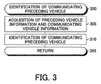
- the CPU determines "Yes" at the step 205 and then, proceeds with the process to a step 207 to start an execution of a routine shown by a flowchart in FIG. 3 to identify the communicating preceding vehicle 11. That is, when the CPU proceeds with the process to the step 207, the CPU starts to execute the routine from a step 300 of FIG. 3 and then, executes processes of steps 305 and 310 described below. Then, the CPU proceeds with the process to a step 209 of FIG. 2 via a step 395.
- Step 305 The CPU acquires preceding vehicle information including data of the operation state amounts of the preceding vehicle from the sensor ECU 60 and acquires communicating vehicle information including data of the operation state amounts of the communicating vehicles from the wireless communication control ECU 80.
- Step 310 The CPU identifies the communicating preceding vehicle 11 among the communicating vehicles on the basis of the operation state amounts of the communicating vehicles included in the communicating vehicle information and the operation state amounts of the preceding vehicle 11 included in the preceding vehicle information. For example, the CPU calculates or estimates the traveling speed of the preceding vehicle 11 on the basis of the relative traveling speed dSPD acquired by the own vehicle sensor 61 and the own vehicle speed SPDj. Then, when the degree of the similarity between the calculated traveling speed of the preceding vehicle 11 and the traveling speed of the communicating vehicle sent from the communicating vehicle through a wireless communication is large, the CPU identifies that communicating vehicle as the communicating preceding vehicle 11.
- the identified communicating vehicle is employed as the communicating preceding vehicle 11 until the CPU determines that the identified communicating vehicle is not the preceding vehicle 11.
- the CPU determines whether or not the identification of the communicating preceding vehicle 11 has been completed at the step 207.
- the CPU determines "Yes" at the step 209 and then, sequentially executes processes of steps 220 to 230 described below.
- the communicating vehicle information will be referred to as "the communicating preceding vehicle information”.
- the CPU employs the actual acceleration Gas as the estimated acceleration Ges when no requested acceleration Gs is included in the communicating preceding vehicle information and only the actual acceleration Gas is included in the communicating preceding vehicle information.
- Step 225 The CPU acquires the inter-vehicle distance D from the sensor ECU 60 and acquires the own vehicle speed SPDj from the brake control ECU 40.
- the sensor ECU 60 executes a separate routine to acquire the inter-vehicle distance D on the basis of the detection signal of the own vehicle sensor 61 and store the acquired inter-vehicle distance D in the RAM of the sensor ECU 60.
- the brake control ECU 40 executes a separate routine to acquire the own vehicle speed SPDj on the basis of the detection signal of the vehicle wheel speed sensors 42 and store the acquired own vehicle speed SPDj in the RAM of the brake control ECU 40.
- the inter-vehicle time T is a time taken for the own vehicle 10 to travel for the inter-vehicle distance D at the own vehicle speed SPDj.
- the CPU proceeds with the process to a step 235 to determine whether or not the estimated acceleration Ges calculated or acquired at the step 220 is larger than zero.
- the CPU determines "Yes" at the step 235 and then, sequentially executes processes of steps 240 to 250 described below. Then, the CPU proceeds with the process to a step 270.
- Step 240 The CPU sets a first correction coefficient Klac for the acceleration as the first correction coefficient K1.
- the first correction coefficient Klac for the acceleration is a constant value smaller than "1 ".
- the first correction coefficient Klac for the acceleration may be "1 ".
- Step 245 The CPU applies the inter-vehicle time T to a look-up table MapK2(T)_ac shown in FIG. 6(A) to acquire the second correction coefficient K2 for the acceleration.
- MapK2(T)_ac when the inter-vehicle time T is between "0" and a time T1, the second correction coefficient K2 for the acceleration is "0".
- the second correction coefficient K2 for the acceleration is a value equal to or smaller than "1" and increases as the inter-vehicle time T increases.
- the second correction coefficient K2 for the acceleration is "1 ".
- the second correction coefficient K2 for the acceleration is a value equal to or smaller than "1" and decreases as the inter-vehicle time T increases.
- the second correction coefficient K2 for the acceleration is "0".
- Step 250 The CPU applies the own vehicle speed SPDj to a look-up table MapK3(SPDj)_ac shown in FIG. 6(C) to acquire the third correction coefficient K3 for the acceleration.
- MapK3(SPDj)_ac when the own vehicle speed SPDj is between "0" and a vehicle speed SPDj1, the third correction coefficient K3 for the acceleration is "0".
- the third correction coefficient K3 for the acceleration is equal to or smaller than "1" and increases as the own vehicle speed SPDj increases.
- the third correction coefficient K3 for the acceleration is "1 ".
- the third correction coefficient K3 for the acceleration is equal to or smaller than "1" and decreases as the own vehicle speed SPDj increases.
- the third correction coefficient K3 for the acceleration is "0".
- the CPU determines "No" at the step 235 and then, sequentially executes processes of steps 255 to 265 described below. Then, the CPU proceeds with the process to a step 270.
- Step 255 The CPU sets a first correction coefficient Klde for the deceleration as the first correction coefficient K1.
- the first correction coefficient Klde for the deceleration is a constant value smaller than "1" and equal to or larger than the first correction coefficient Klac for the acceleration. In this regard, the first correction coefficient Klde for the deceleration may be "1".
- Step 260 The CPU applies the inter-vehicle time T to a look-up table MapK2(T)_de shown in FIG. 6(B) to acquire the second correction coefficient K2 for the deceleration.
- MapK2(T)_de when the inter-vehicle time T is between "0" and a time T5, the second correction coefficient K2 for the deceleration is "1 ".
- the second correction coefficient K2 for the deceleration is equal to or smaller than "1" and decreases as the inter-vehicle time T increases.
- the second correction coefficient K2 for the deceleration is "0".
- Step 265 The CPU applies the own vehicle speed SPDj to a look-up table MapK3(SPDj)_de shown in FIG. 6(D) to acquire the third correction coefficient K3 for the deceleration.
- MapK3(SPDj)_de when the own vehicle speed SPDj is between "0" and a vehicle speed SPDj5, the third correction coefficient K3 for the deceleration is "0".
- the third correction coefficient K3 for the deceleration is equal to or smaller than "1" and increases as the own vehicle speed SPDj increases.
- the third correction coefficient K3 for the deceleration is equal to or smaller than "1” and increases as the own vehicle speed SPDj increases.
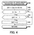
- the CPU proceeds with the process to the step 270, the CPU starts to execute a feedforward requested acceleration calculation routine shown by a flowchart in FIG. 4 to calculate the feedforward requested acceleration GFF. Therefore, when the CPU proceeds with the process to the step 270, the CPU starts to execute the routine from a step 400 of FIG. 4 and then, executes a process of step 405 described below.
- Step 405 The CPU calculates or acquires the feedforward requested acceleration GFF in accordance with a following expression (1).
- GFF Ges ⁇ K 1 ⁇ K 2 ⁇ K 3
- the symbol “Ges” is the estimated acceleration calculated or acquired at the step 220 of FIG. 2
- the symbol “K1” is the first correction value set at the step 240 or 255
- the symbol “K2” is the second correction value set at the step 245 or 260
- the symbol “K3” is the third correction value set at the step 250 or 265.
- the CPU proceeds with the process to a step 415 to determine whether or not the vehicle travel stabilization control signal S included in the communicating vehicle information acquired at the step 207 of FIG. 2 (in particular, at the step 305 of FIG. 3 ) corresponds to a signal Sv which indicates that at least one of the vehicle travel stabilization controls is executed in the communicating preceding vehicle 11.
- the CPU determines "Yes” at the step 415 and then, proceeds with the process to a step 420 to determine whether or not the feedforward requested acceleration GFF is larger than zero.
- the CPU determines "Yes” at the step 420 and then, proceeds with the process to a step 425 to set the feedforward requested acceleration GFF to zero. Then, the CPU proceeds with the process to a step 280 of FIG. 2 via a step 495.
- the CPU determines "No" at the step 420 and then, proceeds with the process directly to the step 280 of FIG. 2 via the step 495.
- the feedforward requested acceleration GFF is limited to a value equal to or smaller than zero.
- the CPU determines "No" at the step 415 and then, proceeds with the process to the step 280 of FIG. 2 via the step 495.
- the CPU proceeds with the process to the step 280, the CPU starts to execute a feedback requested acceleration calculation routine shown by a flowchart in FIG. 5 to calculate the feedback requested acceleration GFB. Therefore, when the CPU proceeds with the process to the step 280, the CPU starts the execution of the routine from a step 500 of FIG. 5 and then, sequentially executes processes of steps 505 and 520 described below.
- Step 505 The CPU acquires the relative traveling speed dSPD from the sensor ECU 60.
- the sensor ECU 60 executes a separate routine to acquire the relative traveling speed dSPD on the basis of the detection signal of the own vehicle sensor 61 and store the acquired relative traveling speed dSPD in the RAM of the sensor ECU 60.
- Step 520 The CPU calculates or acquires the determination-used calculation value P in accordance with a following expression (2).
- P dD ⁇ KFB 1 + dSPD ⁇ KFB 2
- the symbol “dD” is the inter-vehicle distance difference calculated at the step 515
- the symbol “dSPD” is the relative traveling speed acquired at the step 505
- the symbols "KFB1" and “KFB2" are correction coefficients, respectively, which are positive constant values larger than "0".
- the CPU proceeds with the process to a step 525 to determine whether or not the determination-used calculation value P is larger than zero.
- the determination-used calculation value P larger than zero indicates that the acceleration request due to the inter-vehicle distance D occurs in the own vehicle 10 and the determination-used calculation value P equal to or smaller than zero indicates that no acceleration request due to the inter-vehicle distance D occurs in the own vehicle 10.
- the CPU determines "Yes" at the step 525 and then, proceeds with the process to a step 530 to calculate or acquire the feedback requested acceleration GFB in accordance with a following expression (3). Then, the CPU proceeds with the process to a step 285 of FIG. 2 via a step 595.
- GFB dD ⁇ KFB 1 + dSPD ⁇ KFB 2 ⁇ KFB 3
- KFB3 is a correction coefficient which is a positive value larger than "0" and smaller than "1” and decreases as the own vehicle speed SPDj increases.
- the CPU determines "No" at the step 525 and then, proceeds with the process to a step 535 to calculate or acquire the feedback requested acceleration GFB in accordance with a following expression (4). Then, the CPU proceeds with the process to a step 285 of FIG. 2 via the step 595.
- GFB dD ⁇ KFB 1 + dSPD ⁇ KFB 2
- the CPU proceeds with the process to a step 290 to execute processes for activating the engine actuators 32 of the engine or the brake actuator 43 of the braking device such that the requested acceleration Gj calculated at the step 285 is achieved, that is, such that the acceleration (in particular, acceleration/deceleration) of the own vehicle 10 corresponds to the requested acceleration Gj.
- the requested acceleration Gj is larger than zero, the own vehicle 10 is accelerated.
- the requested acceleration Gj is smaller than zero, the own vehicle 10 is decelerated.
- the CPU proceeds with the process to a step 295 to terminate the execution of this routine once.
- the CPU determines "No" at the step 209 and then, proceeds with the process directly to the step 295 to terminate the execution of this routine once.
- the CPU may proceed with the process to the step 280 after the CPU sets the feedforward requested acceleration GFF to zero.
- the feedback control i.e., the inter-vehicle distance control
- the feedforward requested acceleration GFF is a negative value, for example, when the brake pedal operation amount Brkp of the communicating preceding vehicle 11 increases or when any of the vehicle wheel speeds ⁇ a to ⁇ d of the communicating preceding vehicle 11 decreases even under the condition that the vehicle travel stabilization control is executed, the feedforward requested acceleration GFF is considered in the calculation of the requested acceleration Gj of the own vehicle 10 without setting the feedforward requested acceleration GFF to zero. Therefore, when the communicating preceding vehicle 11 starts to decelerate, the own vehicle 10 can be caused to be decelerated with predicting the deceleration of the communicating preceding vehicle 11 and thus, the own vehicle 10 can be caused to travel accurately following the communicating preceding vehicle 11 without decreasing the inter-vehicle distance D.
- the total value of the feedback requested acceleration GFB and the feedforward requested acceleration GFF is calculated as the requested acceleration Gj of the own vehicle 10.
- a weighted average of the feedback requested acceleration GFB and the feedforward requested acceleration GFF may be calculated as the requested acceleration Gj of the own vehicle 10.
- the requested acceleration Gj of the own vehicle 10 may be calculated in accordance with a following expression (5).
- the symbols " ⁇ " and " ⁇ " are positive constants, respectively.
- the constants ⁇ and ⁇ are larger than "0" and smaller than "1" and the constant ⁇ may be a value 1 - ⁇ .
- Gj ⁇ ⁇ GFF + ⁇ ⁇ GFB
- the correction coefficient KFB is a constant positive value larger than "0".
- control apparatus calculates the feedforward requested acceleration GFF on the basis of the requested acceleration Gs and the actual acceleration Gas of the communicating preceding vehicle 11 acquired through the wireless communication.
- control apparatus may calculate the feedforward requested acceleration GFF only on the basis of the requested acceleration Gs without using the actual acceleration Gas or only on the basis of the actual acceleration Gas without using the requested acceleration Gs.
- the control apparatus may be configured to acquire the acceleration pedal operation amount Accp and the brake pedal operation amount Brkp as information on the requested acceleration Gs of the communicating preceding vehicle 11, estimate the requested acceleration Gs of the communicating preceding vehicle 11 on the basis of the acceleration pedal operation amount Accp and the brake pedal operation amount Brkp and calculate the feedforward requested acceleration GFF using the estimated requested acceleration Gs.
- the control apparatus may be configured to acquire the vehicle wheel rotation speeds ⁇ a to ⁇ d or the average vehicle wheel rotation speed ⁇ ave as information on the actual acceleration Gas of the communicating preceding vehicle 11, estimate the actual acceleration Gas of the communicating preceding vehicle 11 on the basis of the vehicle wheel rotation speeds ⁇ a to ⁇ d or the average vehicle wheel rotation speed ⁇ ave and calculate the feedforward requested acceleration GFF using the estimated actual acceleration Gas.
- the invention relates to a control apparatus of a vehicle for causing an own vehicle to travel following a preceding vehicle.
- the apparatus calculates a requested acceleration of the own vehicle on the basis of a feedback requested acceleration for maintaining an inter-vehicle distance to a target distance and a feedforward requested acceleration for causing the own vehicle to travel following the preceding vehicle.
- the apparatus calculates the feedforward requested acceleration on the basis of information on an acceleration of the preceding vehicle sent from the preceding vehicle through a wireless communication.
- the apparatus sets the feedforward requested acceleration to zero when a vehicle travel stabilization control is executed in the preceding vehicle to control a friction braking force applied to at least one of vehicle wheels of the preceding vehicle to stabilize a travel of the preceding vehicle and that the feedforward requested acceleration is larger than zero.
Landscapes
- Engineering & Computer Science (AREA)
- Transportation (AREA)
- Mechanical Engineering (AREA)
- Automation & Control Theory (AREA)
- Chemical & Material Sciences (AREA)
- Combustion & Propulsion (AREA)
- Physics & Mathematics (AREA)
- Human Computer Interaction (AREA)
- General Physics & Mathematics (AREA)
- Mathematical Physics (AREA)
- Control Of Driving Devices And Active Controlling Of Vehicle (AREA)
- Regulating Braking Force (AREA)
- Control Of Vehicle Engines Or Engines For Specific Uses (AREA)
- Traffic Control Systems (AREA)
Applications Claiming Priority (1)
| Application Number | Priority Date | Filing Date | Title |
|---|---|---|---|
| JP2015182352A JP6380309B2 (ja) | 2015-09-15 | 2015-09-15 | 車両の制御装置 |
Publications (3)
| Publication Number | Publication Date |
|---|---|
| EP3144196A2 true EP3144196A2 (fr) | 2017-03-22 |
| EP3144196A3 EP3144196A3 (fr) | 2017-05-17 |
| EP3144196B1 EP3144196B1 (fr) | 2018-09-26 |
Family
ID=56740121
Family Applications (1)
| Application Number | Title | Priority Date | Filing Date |
|---|---|---|---|
| EP16184665.4A Active EP3144196B1 (fr) | 2015-09-15 | 2016-08-18 | Appareil de commande pour véhicule |
Country Status (4)
| Country | Link |
|---|---|
| US (1) | US10118616B2 (fr) |
| EP (1) | EP3144196B1 (fr) |
| JP (1) | JP6380309B2 (fr) |
| CN (1) | CN106515733B (fr) |
Families Citing this family (18)
| Publication number | Priority date | Publication date | Assignee | Title |
|---|---|---|---|---|
| JP6350465B2 (ja) * | 2015-09-15 | 2018-07-04 | トヨタ自動車株式会社 | 車両の制御装置 |
| JP6265191B2 (ja) | 2015-09-15 | 2018-01-24 | トヨタ自動車株式会社 | 車両の制御装置 |
| KR101846631B1 (ko) * | 2015-12-08 | 2018-04-06 | 현대자동차주식회사 | 차량의 주행대열 합류 방법 |
| JP6589894B2 (ja) * | 2017-01-18 | 2019-10-16 | トヨタ自動車株式会社 | 車両の制御装置 |
| US10442440B2 (en) * | 2017-06-01 | 2019-10-15 | GM Global Technology Operations LLC | System and method for estimating cutoff duration of a vehicle |
| CN109421711B (zh) * | 2017-08-28 | 2021-07-13 | 腾讯科技(北京)有限公司 | 跟车速度控制方法、装置、系统、计算机设备及存储介质 |
| MX2020005177A (es) | 2017-11-22 | 2020-08-20 | Polaris Inc | Sistema antibloqueo de frenado conmutable para vehiculo utilitario. |
| CN107963081B (zh) * | 2017-11-27 | 2019-11-15 | 财团法人车辆研究测试中心 | 自适应车速控制方法及其自适应车速控制装置 |
| JP7000214B2 (ja) * | 2018-03-20 | 2022-01-19 | 本田技研工業株式会社 | 車両用制御装置 |
| JP7015005B2 (ja) * | 2018-11-19 | 2022-02-02 | トヨタ自動車株式会社 | 車両の制動力制御装置 |
| US11851059B2 (en) * | 2019-02-14 | 2023-12-26 | Mitsubishi Electric Corporation | Vehicle-to-vehicle distance control device |
| US11225232B2 (en) * | 2019-12-30 | 2022-01-18 | Chongqing Jinkang Powertrain New Energy Co., Ltd. | Fuzzy logic based traction control for electric vehicles |
| US12110024B2 (en) * | 2020-12-29 | 2024-10-08 | GM Global Technology Operations LLC | Consideration of acceleration lag in lead vehicle to enhance host vehicle operation |
| JP7484788B2 (ja) * | 2021-03-29 | 2024-05-16 | 株式会社アドヴィックス | 車両の制動制御装置 |
| CN113335279B (zh) * | 2021-07-22 | 2022-08-23 | 中国第一汽车股份有限公司 | 自适应巡航控制系统起步控制方法、装置、设备及介质 |
| EP4140839B1 (fr) * | 2021-08-31 | 2024-10-30 | Volvo Truck Corporation | Commande de véhicule basé sur une limite de dérapage configurée de manière dynamique |
| US11718299B2 (en) * | 2021-10-18 | 2023-08-08 | Continental Automotive Systems, Inc. | Feed-forward compensation to manage longitudinal disturbance during brake-to-steer |
| US20250313202A1 (en) * | 2024-04-08 | 2025-10-09 | Torc Robotics, Inc. | System and method for longitudinal acceleration planning |
Citations (2)
| Publication number | Priority date | Publication date | Assignee | Title |
|---|---|---|---|---|
| JP5522193B2 (ja) | 2012-04-24 | 2014-06-18 | トヨタ自動車株式会社 | 先行車特定装置 |
| JP2015051716A (ja) | 2013-09-06 | 2015-03-19 | トヨタ自動車株式会社 | 車両走行制御装置 |
Family Cites Families (21)
| Publication number | Priority date | Publication date | Assignee | Title |
|---|---|---|---|---|
| JPH08318765A (ja) * | 1995-05-25 | 1996-12-03 | Hitachi Ltd | 情報化自動車制御装置及び方法 |
| JP3480484B2 (ja) * | 1997-06-27 | 2003-12-22 | 三菱ふそうトラック・バス株式会社 | 自動追従走行システム |
| JP2000105900A (ja) * | 1998-09-29 | 2000-04-11 | Koyo Seiko Co Ltd | 車両用制御装置 |
| DE10007501A1 (de) * | 2000-02-18 | 2001-09-13 | Daimler Chrysler Ag | Verfahren und Vorrichtung zur Erfassung und Überwachung einer Mehrzahl von vorausfahrenden Fahrzeugen |
| US6529814B2 (en) * | 2000-05-16 | 2003-03-04 | Nissan Motor Co., Ltd. | System and method for controlling vehicle velocity and inter-vehicle distance |
| JP3649108B2 (ja) * | 2000-09-14 | 2005-05-18 | 日産自動車株式会社 | 車両用追従走行制御装置 |
| JP4998091B2 (ja) * | 2007-05-30 | 2012-08-15 | トヨタ自動車株式会社 | 車間距離制御装置 |
| JP2009051310A (ja) * | 2007-08-24 | 2009-03-12 | Advics:Kk | 車両走行制御装置 |
| JP2009067358A (ja) * | 2007-09-18 | 2009-04-02 | Advics:Kk | 車両自動走行制御装置 |
| US8352147B2 (en) * | 2007-11-26 | 2013-01-08 | Equos Research Co., Ltd. | Vehicle control device |
| JP4692555B2 (ja) * | 2008-02-08 | 2011-06-01 | 日産自動車株式会社 | 車両用追従走行制御装置 |
| DE102008011228B4 (de) * | 2008-02-26 | 2026-01-22 | Robert Bosch Gmbh | Verfahren zur Unterstützung eines Nutzers eines Fahrzeugs, Steuereinrichtung für ein Fahrerassistenzsystem eines Fahrzeugs und Fahrzeug mit einer derartigen Steuereinrichtung |
| US8265850B2 (en) * | 2009-02-02 | 2012-09-11 | GM Global Technology Operations LLC | Method and apparatus for target vehicle following control for adaptive cruise control |
| JP5573461B2 (ja) | 2010-07-27 | 2014-08-20 | トヨタ自動車株式会社 | 車両制御システム |
| DE102010046236A1 (de) * | 2010-09-22 | 2011-05-12 | Daimler Ag | Verfahren zur Regelung der Längsbewegung eines Fahrzeuges und Fahrerassistenzsystem |
| JP5652364B2 (ja) * | 2011-09-24 | 2015-01-14 | 株式会社デンソー | 車両用挙動制御装置 |
| KR101305196B1 (ko) * | 2011-10-19 | 2013-09-12 | 현대자동차주식회사 | 하이브리드 차량의 차간거리 제어장치 및 방법 |
| GB201215963D0 (en) * | 2012-09-06 | 2012-10-24 | Jaguar Cars | Vehicle control system and method |
| JP6015329B2 (ja) * | 2012-10-11 | 2016-10-26 | 株式会社デンソー | 隊列走行システム及び隊列走行装置 |
| JP5998897B2 (ja) * | 2012-12-10 | 2016-09-28 | トヨタ自動車株式会社 | 車間距離制御装置 |
| US9666079B2 (en) * | 2015-08-20 | 2017-05-30 | Harman International Industries, Incorporated | Systems and methods for driver assistance |
-
2015
- 2015-09-15 JP JP2015182352A patent/JP6380309B2/ja active Active
-
2016
- 2016-08-18 EP EP16184665.4A patent/EP3144196B1/fr active Active
- 2016-09-02 US US15/256,243 patent/US10118616B2/en active Active
- 2016-09-07 CN CN201610806559.2A patent/CN106515733B/zh active Active
Patent Citations (2)
| Publication number | Priority date | Publication date | Assignee | Title |
|---|---|---|---|---|
| JP5522193B2 (ja) | 2012-04-24 | 2014-06-18 | トヨタ自動車株式会社 | 先行車特定装置 |
| JP2015051716A (ja) | 2013-09-06 | 2015-03-19 | トヨタ自動車株式会社 | 車両走行制御装置 |
Also Published As
| Publication number | Publication date |
|---|---|
| CN106515733B (zh) | 2018-12-18 |
| EP3144196A3 (fr) | 2017-05-17 |
| EP3144196B1 (fr) | 2018-09-26 |
| US20170072953A1 (en) | 2017-03-16 |
| US10118616B2 (en) | 2018-11-06 |
| JP6380309B2 (ja) | 2018-08-29 |
| CN106515733A (zh) | 2017-03-22 |
| JP2017056810A (ja) | 2017-03-23 |
Similar Documents
| Publication | Publication Date | Title |
|---|---|---|
| EP3144196B1 (fr) | Appareil de commande pour véhicule | |
| US9914455B2 (en) | Control apparatus of vehicle | |
| EP3144916A2 (fr) | Appareil de commande de véhicule et système de voyage suivant | |
| EP3144198B1 (fr) | Appareil de commande pour véhicule | |
| US6889140B2 (en) | Collision avoidance control system for vehicle | |
| JP6862344B2 (ja) | 車間距離を制御する方法 | |
| US12036988B2 (en) | Method and control unit for operating an adaptive cruise controller | |
| JP4497231B2 (ja) | 車両用速度制御装置 | |
| JP6512137B2 (ja) | 車両走行制御装置 | |
| EP1484212B1 (fr) | Dispositif de prediction du potentiel de risque et système d'assistance à la conduite pour un véhicule automobile | |
| CN110431058B (zh) | 行驶控制装置、车辆及行驶控制方法 | |
| JP5146297B2 (ja) | 車間距離制御装置 | |
| CN113613966A (zh) | 车辆的制动控制装置 | |
| CN104395157A (zh) | 车辆的行驶支援装置 | |
| JP6361886B2 (ja) | 車両走行制御装置 | |
| US12570284B2 (en) | Autonomous driving method and device for a motorized land vehicle | |
| JP6380308B2 (ja) | 車両走行制御装置 | |
| JP7771895B2 (ja) | 車両の制御装置 | |
| US20250136111A1 (en) | Travel control device | |
| JP6458692B2 (ja) | 車両制御装置 |
Legal Events
| Date | Code | Title | Description |
|---|---|---|---|
| PUAI | Public reference made under article 153(3) epc to a published international application that has entered the european phase |
Free format text: ORIGINAL CODE: 0009012 |
|
| STAA | Information on the status of an ep patent application or granted ep patent |
Free format text: STATUS: REQUEST FOR EXAMINATION WAS MADE |
|
| 17P | Request for examination filed |
Effective date: 20160818 |
|
| AK | Designated contracting states |
Kind code of ref document: A2 Designated state(s): AL AT BE BG CH CY CZ DE DK EE ES FI FR GB GR HR HU IE IS IT LI LT LU LV MC MK MT NL NO PL PT RO RS SE SI SK SM TR |
|
| AX | Request for extension of the european patent |
Extension state: BA ME |
|
| PUAL | Search report despatched |
Free format text: ORIGINAL CODE: 0009013 |
|
| AK | Designated contracting states |
Kind code of ref document: A3 Designated state(s): AL AT BE BG CH CY CZ DE DK EE ES FI FR GB GR HR HU IE IS IT LI LT LU LV MC MK MT NL NO PL PT RO RS SE SI SK SM TR |
|
| AX | Request for extension of the european patent |
Extension state: BA ME |
|
| RIC1 | Information provided on ipc code assigned before grant |
Ipc: B60W 10/184 20120101ALI20170411BHEP Ipc: G08G 1/00 20060101ALI20170411BHEP Ipc: B60W 30/16 20120101AFI20170411BHEP Ipc: B60W 10/04 20060101ALI20170411BHEP Ipc: B60W 50/00 20060101ALI20170411BHEP Ipc: B60W 50/06 20060101ALI20170411BHEP |
|
| GRAP | Despatch of communication of intention to grant a patent |
Free format text: ORIGINAL CODE: EPIDOSNIGR1 |
|
| STAA | Information on the status of an ep patent application or granted ep patent |
Free format text: STATUS: GRANT OF PATENT IS INTENDED |
|
| RIC1 | Information provided on ipc code assigned before grant |
Ipc: G08G 1/00 20060101ALI20180228BHEP Ipc: B60W 50/00 20060101ALI20180228BHEP Ipc: B60W 50/06 20060101ALI20180228BHEP Ipc: B60W 10/04 20060101ALI20180228BHEP Ipc: B60W 10/184 20120101ALI20180228BHEP Ipc: B60W 30/16 20120101AFI20180228BHEP |
|
| INTG | Intention to grant announced |
Effective date: 20180320 |
|
| GRAS | Grant fee paid |
Free format text: ORIGINAL CODE: EPIDOSNIGR3 |
|
| GRAA | (expected) grant |
Free format text: ORIGINAL CODE: 0009210 |
|
| STAA | Information on the status of an ep patent application or granted ep patent |
Free format text: STATUS: THE PATENT HAS BEEN GRANTED |
|
| AK | Designated contracting states |
Kind code of ref document: B1 Designated state(s): AL AT BE BG CH CY CZ DE DK EE ES FI FR GB GR HR HU IE IS IT LI LT LU LV MC MK MT NL NO PL PT RO RS SE SI SK SM TR |
|
| REG | Reference to a national code |
Ref country code: GB Ref legal event code: FG4D |
|
| REG | Reference to a national code |
Ref country code: CH Ref legal event code: EP |
|
| REG | Reference to a national code |
Ref country code: AT Ref legal event code: REF Ref document number: 1045636 Country of ref document: AT Kind code of ref document: T Effective date: 20181015 |
|
| REG | Reference to a national code |
Ref country code: IE Ref legal event code: FG4D |
|
| REG | Reference to a national code |
Ref country code: DE Ref legal event code: R096 Ref document number: 602016005959 Country of ref document: DE |
|
| REG | Reference to a national code |
Ref country code: DE Ref legal event code: R084 Ref document number: 602016005959 Country of ref document: DE |
|
| REG | Reference to a national code |
Ref country code: GB Ref legal event code: 746 Effective date: 20181228 |
|
| REG | Reference to a national code |
Ref country code: NL Ref legal event code: MP Effective date: 20180926 |
|
| PG25 | Lapsed in a contracting state [announced via postgrant information from national office to epo] |
Ref country code: NO Free format text: LAPSE BECAUSE OF FAILURE TO SUBMIT A TRANSLATION OF THE DESCRIPTION OR TO PAY THE FEE WITHIN THE PRESCRIBED TIME-LIMIT Effective date: 20181226 Ref country code: GR Free format text: LAPSE BECAUSE OF FAILURE TO SUBMIT A TRANSLATION OF THE DESCRIPTION OR TO PAY THE FEE WITHIN THE PRESCRIBED TIME-LIMIT Effective date: 20181227 Ref country code: FI Free format text: LAPSE BECAUSE OF FAILURE TO SUBMIT A TRANSLATION OF THE DESCRIPTION OR TO PAY THE FEE WITHIN THE PRESCRIBED TIME-LIMIT Effective date: 20180926 Ref country code: RS Free format text: LAPSE BECAUSE OF FAILURE TO SUBMIT A TRANSLATION OF THE DESCRIPTION OR TO PAY THE FEE WITHIN THE PRESCRIBED TIME-LIMIT Effective date: 20180926 Ref country code: LT Free format text: LAPSE BECAUSE OF FAILURE TO SUBMIT A TRANSLATION OF THE DESCRIPTION OR TO PAY THE FEE WITHIN THE PRESCRIBED TIME-LIMIT Effective date: 20180926 Ref country code: BG Free format text: LAPSE BECAUSE OF FAILURE TO SUBMIT A TRANSLATION OF THE DESCRIPTION OR TO PAY THE FEE WITHIN THE PRESCRIBED TIME-LIMIT Effective date: 20181226 |
|
| REG | Reference to a national code |
Ref country code: LT Ref legal event code: MG4D |
|
| PG25 | Lapsed in a contracting state [announced via postgrant information from national office to epo] |
Ref country code: AL Free format text: LAPSE BECAUSE OF FAILURE TO SUBMIT A TRANSLATION OF THE DESCRIPTION OR TO PAY THE FEE WITHIN THE PRESCRIBED TIME-LIMIT Effective date: 20180926 Ref country code: LV Free format text: LAPSE BECAUSE OF FAILURE TO SUBMIT A TRANSLATION OF THE DESCRIPTION OR TO PAY THE FEE WITHIN THE PRESCRIBED TIME-LIMIT Effective date: 20180926 Ref country code: HR Free format text: LAPSE BECAUSE OF FAILURE TO SUBMIT A TRANSLATION OF THE DESCRIPTION OR TO PAY THE FEE WITHIN THE PRESCRIBED TIME-LIMIT Effective date: 20180926 |
|
| REG | Reference to a national code |
Ref country code: AT Ref legal event code: MK05 Ref document number: 1045636 Country of ref document: AT Kind code of ref document: T Effective date: 20180926 |
|
| PG25 | Lapsed in a contracting state [announced via postgrant information from national office to epo] |
Ref country code: AT Free format text: LAPSE BECAUSE OF FAILURE TO SUBMIT A TRANSLATION OF THE DESCRIPTION OR TO PAY THE FEE WITHIN THE PRESCRIBED TIME-LIMIT Effective date: 20180926 Ref country code: NL Free format text: LAPSE BECAUSE OF FAILURE TO SUBMIT A TRANSLATION OF THE DESCRIPTION OR TO PAY THE FEE WITHIN THE PRESCRIBED TIME-LIMIT Effective date: 20180926 Ref country code: ES Free format text: LAPSE BECAUSE OF FAILURE TO SUBMIT A TRANSLATION OF THE DESCRIPTION OR TO PAY THE FEE WITHIN THE PRESCRIBED TIME-LIMIT Effective date: 20180926 Ref country code: IS Free format text: LAPSE BECAUSE OF FAILURE TO SUBMIT A TRANSLATION OF THE DESCRIPTION OR TO PAY THE FEE WITHIN THE PRESCRIBED TIME-LIMIT Effective date: 20190126 Ref country code: PL Free format text: LAPSE BECAUSE OF FAILURE TO SUBMIT A TRANSLATION OF THE DESCRIPTION OR TO PAY THE FEE WITHIN THE PRESCRIBED TIME-LIMIT Effective date: 20180926 Ref country code: CZ Free format text: LAPSE BECAUSE OF FAILURE TO SUBMIT A TRANSLATION OF THE DESCRIPTION OR TO PAY THE FEE WITHIN THE PRESCRIBED TIME-LIMIT Effective date: 20180926 Ref country code: RO Free format text: LAPSE BECAUSE OF FAILURE TO SUBMIT A TRANSLATION OF THE DESCRIPTION OR TO PAY THE FEE WITHIN THE PRESCRIBED TIME-LIMIT Effective date: 20180926 Ref country code: EE Free format text: LAPSE BECAUSE OF FAILURE TO SUBMIT A TRANSLATION OF THE DESCRIPTION OR TO PAY THE FEE WITHIN THE PRESCRIBED TIME-LIMIT Effective date: 20180926 Ref country code: IT Free format text: LAPSE BECAUSE OF FAILURE TO SUBMIT A TRANSLATION OF THE DESCRIPTION OR TO PAY THE FEE WITHIN THE PRESCRIBED TIME-LIMIT Effective date: 20180926 |
|
| PG25 | Lapsed in a contracting state [announced via postgrant information from national office to epo] |
Ref country code: PT Free format text: LAPSE BECAUSE OF FAILURE TO SUBMIT A TRANSLATION OF THE DESCRIPTION OR TO PAY THE FEE WITHIN THE PRESCRIBED TIME-LIMIT Effective date: 20190126 Ref country code: SK Free format text: LAPSE BECAUSE OF FAILURE TO SUBMIT A TRANSLATION OF THE DESCRIPTION OR TO PAY THE FEE WITHIN THE PRESCRIBED TIME-LIMIT Effective date: 20180926 Ref country code: SM Free format text: LAPSE BECAUSE OF FAILURE TO SUBMIT A TRANSLATION OF THE DESCRIPTION OR TO PAY THE FEE WITHIN THE PRESCRIBED TIME-LIMIT Effective date: 20180926 |
|
| REG | Reference to a national code |
Ref country code: DE Ref legal event code: R097 Ref document number: 602016005959 Country of ref document: DE |
|
| PG25 | Lapsed in a contracting state [announced via postgrant information from national office to epo] |
Ref country code: DK Free format text: LAPSE BECAUSE OF FAILURE TO SUBMIT A TRANSLATION OF THE DESCRIPTION OR TO PAY THE FEE WITHIN THE PRESCRIBED TIME-LIMIT Effective date: 20180926 |
|
| PLBE | No opposition filed within time limit |
Free format text: ORIGINAL CODE: 0009261 |
|
| STAA | Information on the status of an ep patent application or granted ep patent |
Free format text: STATUS: NO OPPOSITION FILED WITHIN TIME LIMIT |
|
| 26N | No opposition filed |
Effective date: 20190627 |
|
| PG25 | Lapsed in a contracting state [announced via postgrant information from national office to epo] |
Ref country code: SI Free format text: LAPSE BECAUSE OF FAILURE TO SUBMIT A TRANSLATION OF THE DESCRIPTION OR TO PAY THE FEE WITHIN THE PRESCRIBED TIME-LIMIT Effective date: 20180926 |
|
| PG25 | Lapsed in a contracting state [announced via postgrant information from national office to epo] |
Ref country code: TR Free format text: LAPSE BECAUSE OF FAILURE TO SUBMIT A TRANSLATION OF THE DESCRIPTION OR TO PAY THE FEE WITHIN THE PRESCRIBED TIME-LIMIT Effective date: 20180926 |
|
| PG25 | Lapsed in a contracting state [announced via postgrant information from national office to epo] |
Ref country code: MC Free format text: LAPSE BECAUSE OF FAILURE TO SUBMIT A TRANSLATION OF THE DESCRIPTION OR TO PAY THE FEE WITHIN THE PRESCRIBED TIME-LIMIT Effective date: 20180926 Ref country code: LI Free format text: LAPSE BECAUSE OF NON-PAYMENT OF DUE FEES Effective date: 20190831 Ref country code: CH Free format text: LAPSE BECAUSE OF NON-PAYMENT OF DUE FEES Effective date: 20190831 Ref country code: LU Free format text: LAPSE BECAUSE OF NON-PAYMENT OF DUE FEES Effective date: 20190818 |
|
| REG | Reference to a national code |
Ref country code: BE Ref legal event code: MM Effective date: 20190831 |
|
| PG25 | Lapsed in a contracting state [announced via postgrant information from national office to epo] |
Ref country code: IE Free format text: LAPSE BECAUSE OF NON-PAYMENT OF DUE FEES Effective date: 20190818 |
|
| PG25 | Lapsed in a contracting state [announced via postgrant information from national office to epo] |
Ref country code: BE Free format text: LAPSE BECAUSE OF NON-PAYMENT OF DUE FEES Effective date: 20190831 |
|
| PG25 | Lapsed in a contracting state [announced via postgrant information from national office to epo] |
Ref country code: CY Free format text: LAPSE BECAUSE OF FAILURE TO SUBMIT A TRANSLATION OF THE DESCRIPTION OR TO PAY THE FEE WITHIN THE PRESCRIBED TIME-LIMIT Effective date: 20180926 |
|
| PG25 | Lapsed in a contracting state [announced via postgrant information from national office to epo] |
Ref country code: SE Free format text: LAPSE BECAUSE OF NON-PAYMENT OF DUE FEES Effective date: 20180926 |
|
| PG25 | Lapsed in a contracting state [announced via postgrant information from national office to epo] |
Ref country code: HU Free format text: LAPSE BECAUSE OF FAILURE TO SUBMIT A TRANSLATION OF THE DESCRIPTION OR TO PAY THE FEE WITHIN THE PRESCRIBED TIME-LIMIT; INVALID AB INITIO Effective date: 20160818 Ref country code: MT Free format text: LAPSE BECAUSE OF FAILURE TO SUBMIT A TRANSLATION OF THE DESCRIPTION OR TO PAY THE FEE WITHIN THE PRESCRIBED TIME-LIMIT Effective date: 20180926 |
|
| PG25 | Lapsed in a contracting state [announced via postgrant information from national office to epo] |
Ref country code: MK Free format text: LAPSE BECAUSE OF FAILURE TO SUBMIT A TRANSLATION OF THE DESCRIPTION OR TO PAY THE FEE WITHIN THE PRESCRIBED TIME-LIMIT Effective date: 20180926 |
|
| P01 | Opt-out of the competence of the unified patent court (upc) registered |
Effective date: 20230427 |
|
| PGFP | Annual fee paid to national office [announced via postgrant information from national office to epo] |
Ref country code: GB Payment date: 20250626 Year of fee payment: 10 |
|
| PGFP | Annual fee paid to national office [announced via postgrant information from national office to epo] |
Ref country code: FR Payment date: 20250610 Year of fee payment: 10 |
|
| PGFP | Annual fee paid to national office [announced via postgrant information from national office to epo] |
Ref country code: DE Payment date: 20250624 Year of fee payment: 10 |