EP3144225B1 - Système de circulation d'aéronef pour cabines de passagers - Google Patents
Système de circulation d'aéronef pour cabines de passagers Download PDFInfo
- Publication number
- EP3144225B1 EP3144225B1 EP16194056.4A EP16194056A EP3144225B1 EP 3144225 B1 EP3144225 B1 EP 3144225B1 EP 16194056 A EP16194056 A EP 16194056A EP 3144225 B1 EP3144225 B1 EP 3144225B1
- Authority
- EP
- European Patent Office
- Prior art keywords
- air
- suite
- passenger cabin
- circulation
- inlet
- Prior art date
- Legal status (The legal status is an assumption and is not a legal conclusion. Google has not performed a legal analysis and makes no representation as to the accuracy of the status listed.)
- Active
Links
Images


Classifications
-
- B—PERFORMING OPERATIONS; TRANSPORTING
- B64—AIRCRAFT; AVIATION; COSMONAUTICS
- B64D—EQUIPMENT FOR FITTING IN OR TO AIRCRAFT; FLIGHT SUITS; PARACHUTES; ARRANGEMENT OR MOUNTING OF POWER PLANTS OR PROPULSION TRANSMISSIONS IN AIRCRAFT
- B64D13/00—Arrangements or adaptations of air-treatment apparatus for aircraft crew or passengers, or freight space
-
- B—PERFORMING OPERATIONS; TRANSPORTING
- B64—AIRCRAFT; AVIATION; COSMONAUTICS
- B64D—EQUIPMENT FOR FITTING IN OR TO AIRCRAFT; FLIGHT SUITS; PARACHUTES; ARRANGEMENT OR MOUNTING OF POWER PLANTS OR PROPULSION TRANSMISSIONS IN AIRCRAFT
- B64D11/00—Passenger or crew accommodation; Flight-deck installations not otherwise provided for
- B64D11/06—Arrangements of seats, or adaptations or details specially adapted for aircraft seats
- B64D11/0602—Seat modules, i.e. seat systems including furniture separate from the seat itself
- B64D11/0604—Seat modules, i.e. seat systems including furniture separate from the seat itself including a bed, e.g. cocoon type passenger seat modules
-
- B—PERFORMING OPERATIONS; TRANSPORTING
- B64—AIRCRAFT; AVIATION; COSMONAUTICS
- B64D—EQUIPMENT FOR FITTING IN OR TO AIRCRAFT; FLIGHT SUITS; PARACHUTES; ARRANGEMENT OR MOUNTING OF POWER PLANTS OR PROPULSION TRANSMISSIONS IN AIRCRAFT
- B64D13/00—Arrangements or adaptations of air-treatment apparatus for aircraft crew or passengers, or freight space
- B64D13/06—Arrangements or adaptations of air-treatment apparatus for aircraft crew or passengers, or freight space the air being conditioned
- B64D2013/0603—Environmental Control Systems
- B64D2013/0625—Environmental Control Systems comprising means for distribution effusion of conditioned air in the cabin
-
- B—PERFORMING OPERATIONS; TRANSPORTING
- B64—AIRCRAFT; AVIATION; COSMONAUTICS
- B64D—EQUIPMENT FOR FITTING IN OR TO AIRCRAFT; FLIGHT SUITS; PARACHUTES; ARRANGEMENT OR MOUNTING OF POWER PLANTS OR PROPULSION TRANSMISSIONS IN AIRCRAFT
- B64D13/00—Arrangements or adaptations of air-treatment apparatus for aircraft crew or passengers, or freight space
- B64D13/06—Arrangements or adaptations of air-treatment apparatus for aircraft crew or passengers, or freight space the air being conditioned
- B64D2013/0603—Environmental Control Systems
- B64D2013/0651—Environmental Control Systems comprising filters, e.g. dust filters
-
- B—PERFORMING OPERATIONS; TRANSPORTING
- B64—AIRCRAFT; AVIATION; COSMONAUTICS
- B64D—EQUIPMENT FOR FITTING IN OR TO AIRCRAFT; FLIGHT SUITS; PARACHUTES; ARRANGEMENT OR MOUNTING OF POWER PLANTS OR PROPULSION TRANSMISSIONS IN AIRCRAFT
- B64D13/00—Arrangements or adaptations of air-treatment apparatus for aircraft crew or passengers, or freight space
- B64D13/06—Arrangements or adaptations of air-treatment apparatus for aircraft crew or passengers, or freight space the air being conditioned
- B64D2013/0603—Environmental Control Systems
- B64D2013/0655—Environmental Control Systems with zone or personal climate controls
Definitions
- the present disclosure relates generally to aircraft and, in particular, to environmental systems in aircraft. Double particular, the present disclosure relates to a method and apparatus for circulating air in a passenger cabin of an aircraft.
- the environmental control system of an aircraft controls the air supply, temperature, and pressure in the aircraft.
- areas such as the passenger cabin are designed to circulate air within the passenger cabin. With respect to circulating air, vents, grills, ducts, fans and other devices are located within and around the passenger cabin.
- the passenger cabin is typically open and air circulates freely within the passenger cabin without obstructions such system is described in a document WO 2005/052459 A2 for instance.
- suites are provided within the cabin. Suites may be found in first-class passenger cabins. These suites are private sitting areas.
- a suite may provide a private seating area for one or more persons. This private sitting area may be formed by installing walls in a passenger cabin. These walls may cover three or more sides to provide a desired level of privacy and passenger comfort.
- a suite typically has two doors that move to open and close.
- the presence of suites in the passenger cabin may reduce the flow of air that circulates within the passenger cabin.
- the height of the walls and the suite doors affect the flow of air in the entire passenger cabin. As a result, air stagnation and temperature stratification may occur within the suite, in the aisles outside of the suite, and in other areas of the passenger cabin.
- a suite may have louvers on the doors to provide for ventilation of air. Additionally, the suite also may include one or more gasper air outlets. These currently used mechanisms, however, often do not provide a desired circulation within the passenger cabin. Therefore, it would be desirable to have a method and apparatus that takes into account at least some of the issues discussed above, as well as other possible issues.
- an apparatus comprises a passenger cabin which comprises a suite and an inlet system, an outlet system, and a fan system, according to claim 1.
- a passenger cabin which comprises a suite and an inlet system, an outlet system, and a fan system, according to claim 1.
- the illustrative embodiments recognize and take into account one or more different considerations.
- the louvers in the doors of a suite do not provide for active movement of air. Any airflow through the louvers is passive and may not provide a desired level of circulation of air in the passenger cabin.
- the illustrative embodiments also recognize and take into account that the gasper air outlets are designed for providing airflow to the face of a passenger or some other portion of the passenger. These gasper air outlets are not designed to facilitate airflow within the passenger cabin in a manner that provides desired circulation of air.
- an apparatus comprises an input system, an outlet system, and a fan system.
- the inlet system is configured to receive air in a passenger cabin of an aircraft in a location outside of a suite.
- the outlet system is configured to output air received by the inlet system into the interior of the suite.
- the fan system is configured to cause the movement of the air into the inlet system and out of the outlet system. The movement of the air causes a desired circulation of air within the passenger cabin.
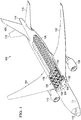
- aircraft 100 has wing 102 and wing 104 attached to body 106.
- Aircraft 100 includes engine 108 attached to wing 102 and engine 110 attached to wing 104.
- Body 106 has nose section 112 and tail section 114.
- Horizontal stabilizer 116, horizontal stabilizer 118, and vertical stabilizer 120 are attached to tail section 114 of body 106.
- passenger cabin 122 is shown in an exposed view of aircraft 100.
- passenger cabin 122 is a first-class passenger cabin and includes suites 128 in addition to seats 130.
- suites 128 are private sitting areas located in passenger cabin 122. These private sitting areas may seat one or more passengers.
- suite 132 includes a seat (not shown) surrounded by walls 134. Walls 134 extend upward from floor 136 of passenger cabin 122 without reaching ceiling 138 in passenger cabin 122.
- an air circulation system may be implemented within passenger cabin 122.
- the air circulation system may provide a desired circulation of air within passenger cabin 122 containing suites 128.
- air circulation environment 200 includes platform 202 in which air 204 may circulate.
- air 204 may circulate within passenger cabin 208 in platform 202.
- platform 202 may take the form of aircraft 100 illustrated in Figure 1 .
- the circulation of air 204 may be facilitated by air circulation system 205.
- air circulation system 205 may be associated with suites 206 in passenger cabin 208.
- desired circulation 210 of air 204 may occur within passenger cabin 208.
- Desired circulation 210 may be a circulation of air 204 such that passenger cabin 208 may reduce or avoid stagnant air, temperature stratification, or other undesirable conditions within suite 212, other suites in suites 206, or other areas within passenger cabin 208 that may result in an undesired experience for passengers.
- air circulation system 205 may be implemented in suite 212 within suites 206.
- air circulation system 205 may comprise circulation units 214.
- circulation unit 216 in circulation units 214 may be associated with suite 212.
- association is a physical association in the depicted examples.
- a first component may be considered to be associated with a second component by being secured to the second component, bonded to the second component, mounted to the second component, welded to the second component, fastened to the second component, and/or connected to the second component in some other suitable manner.
- the first component also may be connected to the second component using a third component.
- the first component may also be considered to be associated with the second component by being formed as part of and/or an extension of the second component.
- suite 212 has walls 218 extending upward from floor 220 of passenger cabin 208 without reaching ceiling 222 of passenger cabin 208.
- an open area is present between top of walls 218 and ceiling 222 in these illustrative examples.
- air circulation system 205 includes a number of different components.
- air circulation system 205 includes inlet system 226, outlet system 228, and fan system 230.
- Inlet system 226 is configured to receive air 204 in passenger cabin 208 in a location outside of suite 212. A part of inlet system 226 is in the location outside of suite 212 to receive air 204 in the location outside of suite 212.
- Outlet system 228 is configured to output air 204 received by inlet system 226 into interior 232 of suite 212.
- Fan system 230 is configured to cause a movement of air 204 into inlet system 226 from outside of suite 212. Fan system 230 is further configured to move air 204 received through inlet system 226 out of outlet system 228 into interior 232 of suite 212.
- circulation unit 216 also may include other components in addition to or in place of the ones illustrated.
- circulation unit 216 also may include filter system 236.
- Filter system 236 may be implemented using a number of different components.
- filter system 236 may include an air filter configured to remove particles such as dust, pollen, mold, and bacteria from the air.
- the air filter may also be a chemical air filter that includes a catalyst to remove various volatile organic compounds or ozone.
- filter system 236 also may include an ultraviolet light unit configured to render bacteria and other undesired particles inert.
- the movement of air 204 by circulation unit 216 may cause air 204 in interior 232 of suite 212 to move upward in suite 212.
- This movement of air 204 in suite 212 may be upward and over walls 218.
- This movement of air 204 may cause air 204 in suite 212 to mix with air 204 outside of suite 212 in passenger cabin 208. In this manner, desired circulation 210 of air 204 may occur within passenger cabin 208.
- desired circulation 210 may occur within passenger cabin 208. Desired circulation 210 may occur even with the presence of suites 206 blocking portions of passenger cabin 208.
- inlet system 226 includes a number of different components.
- inlet system 226 includes inlet grill 300, restrictor 302, and duct 304.
- Inlet grill 300 is located on a wall in walls 218 outside of suite 212. Inlet grill 300 provides an opening to receive air 204 in Figure 2 . In these illustrative examples, the area of inlet grill 300 is shaped such that movement of air 204 into inlet grill 300 from the main passenger aisle of platform 202 is substantially imperceptible to a person near inlet grill 300. In other words, inlet grill 300 is shaped such that a draft is not felt by persons in the main passenger aisle of platform 202. As depicted, restrictor 302 is connected to inlet grill 300. In these illustrative examples, restrictor 302 is configured to connect inlet grill 300 to duct 304.
- Duct 304 is a channel that provides a connection from restrictor 302 to fan system 230 in Figure 2 .
- duct 304 is smaller than inlet grill 300 in platform 202.
- an increase in velocity of air 204 as it passes through restrictor 302 into duct 304 occurs.
- the smaller size may be result of space restrictions in platform 202.
- outlet system 228 includes a number of different components.
- outlet system 228 includes duct 400, diffuser 402, and outlet 404.
- Duct 400 is configured to be connected to fan system 230 in Figure 2 .
- Duct 400 is also connected to diffuser 402 in this illustrative example.
- Diffuser 402 is configured to reduce the velocity of air 204 received through duct 400 from fan system 230 in Figure 2 .
- Outlet 404 is an opening that is located inside suite 212. Outlet 404 may take various forms. For example, outlet 404 may take the form of a grill, nozzle, or some other suitable type of opening.
- diffuser 402 is configured to reduce the velocity of air 204 entering suite 212 as air 204 is output from outlet 404. This reduction in the velocity of air 204 may be such that the movement of air 204 in suite 212 is substantially imperceptible to a person in suite 212.
- the velocity of air 204 in suite 212 may be selected to avoid a feeling of draftiness by a passenger in suite 212.
- the velocities may be selected to avoid a feeling of draftiness on ankles, wrists, head, or other body parts of a passenger.
- FIG. 5 an illustration of a fan system is depicted in accordance with an illustrative embodiment. An illustration of components that may be used to implement fan system 230 in Figure 2 are shown in this figure.
- fan system 230 is comprised of a group of fans 500.
- a group of when used with reference items, means one or more items.
- group of fans 500 is one or more fans.
- a fan in group of fans 500 may be a fan that has a brushless motor. Further, the fan may be selected to avoid generating undesired noise, fumes, smoke, or other undesired conditions when the fan does not operate as desired.
- group of fans 500 are comprised of the same type of fans or different fans when more than one fan is present in group of fans. Of course, different types of fans also may be used.
- platform 202 has been described as taking the form of aircraft 100 in Figure 1 , platform 202 may take other forms.
- platform 202 also may be selected from one of a surface ship, a cruise ship, a spacecraft, a train, or some other suitable type of platform.
- one or more circulation units may be associated with suite 212 in addition to circulation unit 216.
- suite 212 may include two circulation units, four circulation units, or some other number of circulation units. The number of circulation units used may depend on the airflow needed for desired circulation 210 within passenger cabin 208.
- FIG. 6-9 illustrations of a suite are depicted in accordance with an illustrative embodiment.
- a more detailed illustration of suite 132 in passenger cabin 122 in Figure 1 with two circulation units is shown.
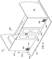
- suite 132 an illustration of an exterior view of a suite is depicted in accordance with an illustrative embodiment. A more detailed illustration of suite 132 is shown in this view. As depicted, suite 132 also includes door 600 and door 602 to provide entry and exit from interior 604 of suite 132.
- suite 132 also has circulation unit 606 and circulation unit 608.
- a portion of the circulation units can be seen on exterior 610 of walls 134 in this view. More specifically, inlet grill 612 in circulation unit 606 and inlet grill 614 in circulation unit 608 can be seen. As depicted, inlet grill 612 and inlet grill 614 are located on lower half 616 of exterior 610 of walls 134. In these illustrative examples, inlet grill 614 may be located on a wall in walls 134 that is adjacent to aisle 618 in passenger cabin 122.
- FIG. 7 another illustration of an exterior view of a suite is depicted in accordance with an illustrative embodiment.
- a transparent view of suite 132 is depicted.
- monuments 700 within interior 604 of walls 134 of suite 132 can be seen.
- circulation unit 606 and circulation unit 608 are configured to be located within monuments 700.
- a monument is a structure.
- a monument may be attached to floor 136.
- a monument may be, for example, a seat, cabinetry, a galley, a credenza, or other structures that may be present in a platform such as an aircraft.
- FIG. 8 an illustration of an interior view of a suite is depicted in accordance with an illustrative embodiment.
- a view of interior 604 of suite 132 is shown.
- monuments 700 include seat 800 and bench 802.
- Gasper unit 804 is configured to provide airflow to a passenger. In these illustrative examples, gasper unit 804 is not configured to aid in circulation of air within the passenger cabin.
- FIG. 9 another illustration of an interior view of a suite is depicted in accordance with an illustrative embodiment.
- a transparent view of interior 604 of suite 132 is shown in this view.
- Circulation unit 606 and circulation unit 608 can be seen located within monuments 700.
- circulation unit 608 is located within bench 802.
- Circulation unit 606 extends through armrest 900 in seat 800 and light unit 902 located behind seat 800.
- the location of circulation unit 608 within bench 802 reduces the visibility of circulation unit 608 to a passenger in suite 132.
- the placement of circulation unit 606 extending through armrest 900 and light unit 902 is an example of an inconspicuous location in suite 132. In this manner, the aesthetics of suite 132 may be increased without a passenger seeing different components of circulation unit 606 and circulation unit 608.
- outlet 904 in circulation unit 608 is located on bench 802.
- Outlet 906 in circulation unit 606 is located on light unit 902.
- Outlet 906 is located on lower half 616 of walls 134 within interior 604 of suite 132.
- FIG 10 and Figure 11 are illustrations of circulation units that may be implemented in a suite in accordance with an illustrative embodiment.
- FIG 10 an illustration of a circulation unit is depicted in accordance with an illustrative embodiment.
- Circulation unit 606 has inlet system 1000, fan system 1002, and outlet system 1004.
- Inlet system 1000 includes inlet grill 612, restrictor 1006, and duct 1008.
- Outlet system 1004 comprises duct 1010, diffuser 1012, and outlet 906.
- fan system 1002 comprises fan 1014.
- Fan 1014 is connected to duct 1008 in inlet system 1000 and duct 1010 in outlet system 1004 in this illustrative example.
- Figure 11 another illustration of a circulation unit is depicted in accordance with an illustrative embodiment. An isometric view of circulation unit 608 is shown in this figure.
- Circulation unit 608 is comprised of inlet system 1100, fan system 1102, and outlet system 1104.
- Inlet system 1100 includes inlet grill 614, restrictor 1106, and duct 1108.
- outlet system 1104 includes duct 1110, diffuser 1112, and outlet 904.
- Fan system 1102 is comprised of fan 1114.
- Fan 1114 is connected to duct 1108 in inlet system 1100 and duct 1110 in outlet system 1104.
- suites typically include multiple heat sources such as a video monitor, electronic boxes, seat actuators, armrest motors, in-flight entertainment systems (IFEs), and other devices that may generate heat.
- the cool air may be used to displace hot-air that rises in the suites in these illustrative examples.
- circulation unit 606 and circulation unit 608 are not meant to imply limitations to the manner in which other illustrative embodiments may be implemented.
- two circulation units are illustrated, other numbers of circulation units may be used.
- only a single circulation unit may be used.
- three or more circulation units may be associated with suite 132.
- the length and shape of the ducts also may vary.
- the ducts are shown having a square cross-section, other ducts may have other shapes.
- the cross-section may be rectangular, circular, oval, or some other suitable shape.
- a circulation unit may have more than one inlet or more than one outlet depending on the particular implementation.
- two inlets may have ducts that connect to a fan.
- a filter system also may be included in one or more of the circulation units.
- the filter system may be included to remove particles or render biological particles in the air inert.
- the filter system may include, for example, an air filter, and ultraviolet light, and other suitable types of filter systems.
- FIG 12 a cross-sectional view of a suite within an aircraft is depicted in accordance with an illustrative embodiment.
- a cross-sectional view of suite 132 is taken along lines 12-12 in Figure 1 .
- air may flow in the direction of arrow 1200 through inlet grill 614 into circulation unit 608. This airflow may pass through restrictor 1106 and duct 1108 to reach fan 1114.
- the air may then flow through duct 1110 to diffuser 1112 as depicted by arrow 1202.
- the air then flows out of outlet 908 into interior 604 of suite 132 as shown by arrows 1204.
- the air may then flow upward over the tops of walls 134 to mix with cabin air outside of suite 132 in passenger cabin 122.
- FIG. 1 and 6 -12 may be combined with components in Figures 2-5 , used with components in Figures 2-5 , or a combination of the two. Additionally, some of the components in Figures 1 and 6 -12 may be illustrative examples of how components shown in block form in Figures 2-5 can be implemented as physical structures.
- FIG. 13 an illustration of a flowchart of a process for circulating air in a passenger cabin is depicted in accordance with an illustrative embodiment.
- the process illustrated in Figure 13 may be implemented in air circulation environment 200 in Figure 2 .
- one or more of the different operations in this flowchart may be implemented using one or more circulation units 214 in air circulation system 205.
- the process begins by moving air in a passenger cabin from an exterior of a suite into an inlet system associated with the suite (operation 1300 ).
- the air is filtered after the air is moved into the inlet system (operation 1302 ).
- the air received by the inlet system is moved into an interior of the suite through an outlet system associated with the suite and connected to the inlet system (operation 1304 ) with the process terminating thereafter.
- the inlet system is indirectly connected to the outlet system by a fan system.
- the different operations may cause a desired circulation of air within the passenger cabin. This process may be performed for one or more suites located in the passenger cabin.
- the flowcharts and block diagrams in the different depicted embodiments illustrate the architecture, functionality, and operation of some possible implementations of apparatuses and methods in an illustrative embodiment.
- each block in the flowcharts or block diagrams may represent a module, a segment, a function, and/or a portion of an operation or step.
- the function or functions noted in the blocks may occur out of the order noted in the figures.
- two blocks shown in succession may be executed substantially concurrently, or the blocks may sometimes be performed in the reverse order, depending upon the functionality involved.
- other blocks may be added in addition to the illustrated blocks in a flowchart or block diagram.
- the filtering in operation 1302 may be amended in some steps.
- aircraft manufacturing and service method 1400 may be described in the context of aircraft manufacturing and service method 1400 as shown in Figure 14 and aircraft 1500 as shown in Figure 15 .
- Figure 14 an illustration of an aircraft manufacturing and service method is depicted in accordance with an illustrative embodiment.
- aircraft manufacturing and service method 1400 may include specification and design 1402 of aircraft 1500 in Figure 15 and material procurement 1404.
- aircraft 1500 in Figure 15 During production, component and subassembly manufacturing 1406 and system integration 1408 of aircraft 1500 in Figure 15 takes place. Thereafter, aircraft 1500 in Figure 15 may go through certification and delivery 1410 in order to be placed in service 1412. While in service 1412 by a customer, aircraft 1500 in Figure 15 is scheduled for routine maintenance and service 1414, which may include modification, reconfiguration, refurbishment, and other maintenance or service.
- Each of the processes of aircraft manufacturing and service method 1400 may be performed or carried out by a system integrator, a third party, and/or an operator.
- the operator may be a customer.
- a system integrator may include, without limitation, any number of aircraft manufacturers and major-system subcontractors
- a third party may include, without limitation, any number of vendors, subcontractors, and suppliers
- an operator may be an airline, a leasing company, a military entity, a service organization, and so on.
- aircraft 1500 is produced by aircraft manufacturing and service method 1400 in Figure 14 and may include airframe 1502 with systems 1504 and interior 1506.
- systems 1504 include one or more of propulsion system 1508, electrical system 1510, hydraulic system 1512, and environmental system 1514. Any number of other systems may be included.
- propulsion system 1508 include one or more of propulsion system 1508, electrical system 1510, hydraulic system 1512, and environmental system 1514. Any number of other systems may be included.
- an aerospace example is shown, different illustrative embodiments may be applied to other industries, such as the automotive industry.
- Apparatuses and methods embodied herein may be employed during at least one of the stages of aircraft manufacturing and service method 1400 in Figure 14 .
- One or more illustrative embodiments may be implemented using system integration 1408 to install circulation units for a circulation system in suites in a passenger cabin in aircraft 1500. Additionally, one or more illustrative embodiments may operate during in-service 1412 to provide desired air circulation within aircraft 1500. Further, one or more illustrative embodiments may be implemented during maintenance and service 1414. For example, circulation units may be added to suites in an aircraft. Circulation units may be installed when suites are installed during maintenance, refurbishment, upgrades, or other operations during maintenance and service 1414.
- one or more illustrative embodiments may provide a more natural desired airflow of air in the passenger cabin.
- the different illustrative embodiments do not have the complexity of environmental systems that draw air from outside of the aircraft.
- the circulation system in the illustrative embodiments may provide a desired flow of air in the cabin through circulation units that may be associated with suites. These circulation units may be installed in existing and new suites. Further, with the use of circulation units, the need for louvers in the doors and gasper units may be reduced or eliminated.
Landscapes
- Engineering & Computer Science (AREA)
- Aviation & Aerospace Engineering (AREA)
- Health & Medical Sciences (AREA)
- General Health & Medical Sciences (AREA)
- Pulmonology (AREA)
- Air-Conditioning For Vehicles (AREA)
Claims (6)
- Appareil comprenant :- une cabine passagers ;- un système d'entrée (226) configuré pour recevoir de l'air (204) dans la cabine passagers (208) ;- un système de sortie (228) configuré pour sortir l'air (204) reçu par le système d'entrée (226) ; et- un système de ventilateur (230) configuré pour provoquer un mouvement de l'air (204) dans le système d'entrée (226) et hors du système de sortie (228), dans lequel le mouvement de l'air (204) provoque une circulation souhaitée (210) de l'air (204) dans la cabine passagers (208) ;caractérisé en ce que ledit appareil comprend en outre une suite (212) présentant une pluralité de parois (218) s'étendant vers le haut depuis un sol (220) de ladite cabine passagers (208) sans atteindre un plafond (22) de ladite cabine passagers (208), ledit système d'entrée (226) étant configuré pour recevoir de l'air (204) dans un emplacement en dehors de ladite suite (212) et ledit système de sortie (228) étant configuré pour sortir l'air (204) reçu par ledit système d'entrée (226) dans un intérieur (232) de la suite (212) ;
en ce que ledit système d'entrée comprend un limiteur (302), un conduit (304) configuré pour être raccordé audit système de ventilateur (230) et une grille d'entrée (300) configurée pour fournir une ouverture pour recevoir de l'air (204), dans lequel ladite grille d'entrée (300) est située sur une moitié inférieure (616) d'un extérieur (610) de parois (218) de ladite suite (212) ;
et en ce que le système de sortie (228) comprend un conduit (304) configuré pour être raccordé audit système de ventilateur (230), un diffuseur (402) et une sortie (404) située sur une moitié inférieure (616) dudit intérieur (232) de parois (218) de ladite suite (212). - Appareil selon la revendication 1 comprenant en outre :
un système de filtre (236). - Appareil selon la revendication 1, dans lequel le système de ventilateur (230) comprend un groupe de ventilateurs (500).
- Appareil selon la revendication 1, dans lequel la circulation souhaitée (210) de l'air (204) dans la cabine passagers (208) est le mouvement de l'air (204) vers le haut dans la suite (212), dans lequel l'air (204) dans la suite (212) se mélange avec l'air (204) en dehors de la suite (212).
- Appareil selon la revendication 1, dans lequel le mouvement de l'air (204) est sensiblement imperceptible à une personne dans la suite (212).
- Appareil selon la revendication 1, dans lequel la cabine passagers (208) est située dans une plateforme (202) sélectionnée parmi un de l'aéronef (100), un bateau de surface, un bateau de croisière, un engin spatial et un train.
Applications Claiming Priority (2)
| Application Number | Priority Date | Filing Date | Title |
|---|---|---|---|
| US13/783,664 US20140248827A1 (en) | 2013-03-04 | 2013-03-04 | Aircraft Circulation System for Passenger Cabins |
| EP14707005.6A EP2931605B1 (fr) | 2013-03-04 | 2014-02-03 | Systeme de circulation de avion pour cabines de passagers |
Related Parent Applications (2)
| Application Number | Title | Priority Date | Filing Date |
|---|---|---|---|
| EP14707005.6A Division EP2931605B1 (fr) | 2013-03-04 | 2014-02-03 | Systeme de circulation de avion pour cabines de passagers |
| EP14707005.6A Division-Into EP2931605B1 (fr) | 2013-03-04 | 2014-02-03 | Systeme de circulation de avion pour cabines de passagers |
Publications (2)
| Publication Number | Publication Date |
|---|---|
| EP3144225A1 EP3144225A1 (fr) | 2017-03-22 |
| EP3144225B1 true EP3144225B1 (fr) | 2018-06-13 |
Family
ID=50185017
Family Applications (2)
| Application Number | Title | Priority Date | Filing Date |
|---|---|---|---|
| EP16194056.4A Active EP3144225B1 (fr) | 2013-03-04 | 2014-02-03 | Système de circulation d'aéronef pour cabines de passagers |
| EP14707005.6A Active EP2931605B1 (fr) | 2013-03-04 | 2014-02-03 | Systeme de circulation de avion pour cabines de passagers |
Family Applications After (1)
| Application Number | Title | Priority Date | Filing Date |
|---|---|---|---|
| EP14707005.6A Active EP2931605B1 (fr) | 2013-03-04 | 2014-02-03 | Systeme de circulation de avion pour cabines de passagers |
Country Status (3)
| Country | Link |
|---|---|
| US (1) | US20140248827A1 (fr) |
| EP (2) | EP3144225B1 (fr) |
| WO (1) | WO2014137515A1 (fr) |
Families Citing this family (12)
| Publication number | Priority date | Publication date | Assignee | Title |
|---|---|---|---|---|
| US20130246008A1 (en) * | 2012-03-15 | 2013-09-19 | Chao-Hsin Lin | Cabin airflow modeling |
| US20150157884A1 (en) * | 2013-05-14 | 2015-06-11 | The Boeing Company | Oxygen enriched user compartment on an aircraft |
| US10273010B2 (en) * | 2013-09-04 | 2019-04-30 | The Boeing Company | Systems and methods for refrigerating galley compartments |
| US10614329B2 (en) | 2014-06-13 | 2020-04-07 | B/E Aerospace, Inc. | Apparatus and method for providing attitude reference for vehicle passengers |
| US10452934B1 (en) | 2014-06-13 | 2019-10-22 | B/E Aerospace, Inc. | Apparatus and method for providing attitude reference for vehicle passengers |
| US10558877B2 (en) | 2014-06-13 | 2020-02-11 | B/E Aerospace, Inc. | Apparatus and method for providing attitude reference for vehicle passengers |
| US10949689B2 (en) | 2014-06-13 | 2021-03-16 | B/E Aerospace, Inc. | Apparatus and method for providing attitude reference for vehicle passengers |
| EP3263444B1 (fr) | 2016-06-30 | 2020-04-01 | Cathay Pacific Airways Limited | Module de cabine et agencement pour un aéronef de passagers |
| US10618660B2 (en) * | 2017-11-20 | 2020-04-14 | The Boeing Company | Systems and methods providing airflow to a flight deck |
| EP3929086A1 (fr) * | 2020-06-23 | 2021-12-29 | The Boeing Company | Système de purification d'air |
| US20220041288A1 (en) * | 2020-08-04 | 2022-02-10 | B/E Aerospace, Inc. | Aircraft seats with air vents |
| FR3164448A1 (fr) * | 2024-07-12 | 2026-01-16 | Dassault Aviation | Portion d'aéronef comprenant un système de circulation d'air dans la cabine |
Family Cites Families (43)
| Publication number | Priority date | Publication date | Assignee | Title |
|---|---|---|---|---|
| GB489423A (en) * | 1935-12-17 | 1938-07-24 | Burgess Lab Inc C F | Improvements in ventilating system |
| US2483995A (en) * | 1945-03-17 | 1949-10-04 | Budd Co | Heating system for multiple-room vehicles |
| US2461424A (en) * | 1946-03-25 | 1949-02-08 | Pullman Co | Vehicle heating arrangement |
| US2755638A (en) * | 1953-01-30 | 1956-07-24 | Const Aeronautiques Du Sudoues | Air refrigerating system, in particular for aircraft cockpits |
| US2953103A (en) * | 1957-10-31 | 1960-09-20 | Pullman Co | Combination coach and sleeping car |
| GB1204594A (en) * | 1967-02-14 | 1970-09-09 | Karl Heinz Steigerwald | Device for ventilating or air-conditioning a room or cabin |
| SE359367B (fr) * | 1969-07-11 | 1973-08-27 | Munters C | |
| US3611907A (en) * | 1969-10-16 | 1971-10-12 | Industrial Acoustics Co | Ventilated portable structure |
| US3782362A (en) * | 1971-06-01 | 1974-01-01 | E Puzio | Baby incubator |
| US4129122A (en) * | 1977-04-27 | 1978-12-12 | Sterilaire Medical, Inc. | Patient isolation room with laminar flow feature |
| DE3471155D1 (en) * | 1984-10-08 | 1988-06-16 | Geilinger Ag | System for the covering of the power requirements of a room |
| IT1189629B (it) * | 1986-03-25 | 1988-02-04 | Wabco Westinghouse Spa | Dispositivo diffusore d aria per impianti di climatizzazione dei compartimenti di una carrozza ferroviaria |
| US4819548A (en) * | 1987-05-07 | 1989-04-11 | The Boeing Company | Dual nozzle cabin ventilation system |
| DE4008822A1 (de) * | 1990-03-20 | 1991-09-26 | Draegerwerk Ag | Inkubator mit gleichmaessiger luftfuehrung |
| US5282341A (en) * | 1992-01-10 | 1994-02-01 | Steelcase Inc. | Dynamic workspace module |
| GB2275768B (en) * | 1993-03-03 | 1996-09-18 | Valeo Climate Control Ltd | Ventilation system for a vehicle |
| US5358444A (en) * | 1993-04-27 | 1994-10-25 | Steelcase Inc. | Workstation ventilation system |
| US5759149A (en) * | 1993-12-17 | 1998-06-02 | Hill-Rom, Inc. | Patient thermal support device |
| JP3206891B2 (ja) * | 1997-05-09 | 2001-09-10 | 日本たばこ産業株式会社 | 旅客機内のカーテン式分煙装置 |
| JP3253061B2 (ja) * | 1998-09-04 | 2002-02-04 | 積水ハウス株式会社 | 低気密住宅用自然換気建造物の構造及び自然換気システム |
| DE69923925T2 (de) * | 1998-12-14 | 2006-02-23 | The Boeing Co., Seattle | Unterkunftseinheiten im oberen Bereich der Flugzeugkabine |
| NZ504686A (en) * | 2000-05-22 | 2002-08-28 | Frederick Johnston Needham | Office chair including self contained air conditioning system |
| DE10339077A1 (de) * | 2003-08-26 | 2005-03-31 | Airbus Deutschland Gmbh | Passagierabteil in der Kabine eines Verkehrsflugzeugs |
| USD495048S1 (en) * | 2003-11-20 | 2004-08-24 | Sgc Technologies, L.L.C. | Poke through components |
| GB0327709D0 (en) * | 2003-11-28 | 2003-12-31 | Bombardier Transp Gmbh | Air conditioning assembly |
| JP5208424B2 (ja) * | 2004-02-20 | 2013-06-12 | シンガポール エアラインズ リミテッド | 航空機客室 |
| GB0425323D0 (en) * | 2004-11-17 | 2004-12-22 | Britax Aircraft Interiors Uk L | Aircraft seat |
| US7721990B2 (en) * | 2005-07-29 | 2010-05-25 | Airbus Deutschland Gmbh | Passenger compartment |
| GB2438162A (en) * | 2006-05-19 | 2007-11-21 | British Airways Plc | Reclining aircraft seat convertible into bed |
| EP1878611B1 (fr) * | 2006-07-11 | 2009-03-11 | C.R.F. Società Consortile per Azioni | Siège, en particulier siège de véhicule, avec des moyens pour déviation d'un flux de ventilation basé sur l'effet coanda |
| US20090093206A1 (en) * | 2007-10-09 | 2009-04-09 | Honda Motor Co., Ltd. | Onboard air conditioning system |
| DE102007049926A1 (de) * | 2007-10-18 | 2009-04-23 | Airbus Deutschland Gmbh | System und Verfahren zur Klimatisierung zumindest eines Teilbereichs eines Flugzeugs |
| DE102008025389B4 (de) * | 2007-12-21 | 2013-02-28 | Airbus Operations Gmbh | Verfahren zum Isolieren einer Flugzeugkabinenwand bzw. zum Abkühlen oder Aufwärmen von Flugzeugkabinenluft und dazu geeignete Flugzeugkabinenwand |
| US20100081369A1 (en) * | 2008-09-30 | 2010-04-01 | Space David R | Personal ventilation in an aircraft environment |
| USD623731S1 (en) * | 2010-01-22 | 2010-09-14 | Sgc Technologies, L.L.C. | Poke through |
| US8616063B2 (en) * | 2010-10-01 | 2013-12-31 | Qualmark Corporation | Method and apparatus for thermal control of a multiple chamber test system |
| US8662447B2 (en) * | 2011-06-17 | 2014-03-04 | Be Aerospace, Inc. | Flexible-usage travel suite |
| WO2013138442A1 (fr) * | 2012-03-14 | 2013-09-19 | B/E Aerospace, Inc. | Mini-compartiment individuel à siège convertible en lit pour passager d'avion |
| EP2828161B1 (fr) * | 2012-03-19 | 2019-06-19 | B/E Aerospace Inc. | Salon de classe à tarif majoré pour passagers d'avion |
| CA2868184C (fr) * | 2012-03-22 | 2018-05-15 | Russell Kroll | Agencement des places assises d'un salon pour passagers d'avion |
| KR101371758B1 (ko) * | 2012-12-21 | 2014-03-10 | 갑을오토텍(주) | 차량의 암레스트 |
| KR101371757B1 (ko) * | 2012-12-21 | 2014-03-07 | 현대자동차(주) | 차량의 암레스트 |
| US9050382B2 (en) * | 2013-03-12 | 2015-06-09 | Peter Carr | Close proximity airborne influenza/pathogen mitigator |
-
2013
- 2013-03-04 US US13/783,664 patent/US20140248827A1/en not_active Abandoned
-
2014
- 2014-02-03 EP EP16194056.4A patent/EP3144225B1/fr active Active
- 2014-02-03 WO PCT/US2014/014386 patent/WO2014137515A1/fr not_active Ceased
- 2014-02-03 EP EP14707005.6A patent/EP2931605B1/fr active Active
Non-Patent Citations (1)
| Title |
|---|
| None * |
Also Published As
| Publication number | Publication date |
|---|---|
| US20140248827A1 (en) | 2014-09-04 |
| EP3144225A1 (fr) | 2017-03-22 |
| EP2931605B1 (fr) | 2017-01-11 |
| WO2014137515A1 (fr) | 2014-09-12 |
| EP2931605A1 (fr) | 2015-10-21 |
Similar Documents
| Publication | Publication Date | Title |
|---|---|---|
| EP3144225B1 (fr) | Système de circulation d'aéronef pour cabines de passagers | |
| JP6261192B2 (ja) | 環境制御システム、及び同システムの操作方法 | |
| US7252267B2 (en) | Aircraft archway architecture | |
| US9950798B2 (en) | Air conditioning system and methods of assembling the same | |
| US8206475B2 (en) | Entrainment air flow control and filtration devices | |
| US20100081369A1 (en) | Personal ventilation in an aircraft environment | |
| DE102010005902B4 (de) | Flugzeug mit mindestens einem druckbeaufschlagten Rumpfbereich und mindestens einem nicht druckbeaufschlagten Bereich sowie Verfahren zum Belüften eines nicht druckbeaufschlagten Bereichs eines Flugzeugs | |
| US11999490B2 (en) | Air curtain systems and methods for vehicle cabins | |
| US12214886B2 (en) | Ventilation systems and methods for internal cabins of vehicles | |
| US20130040546A1 (en) | Aircraft and method for climatizing at least a part-region of the interior of an aircraft | |
| EP3075658B1 (fr) | Système d'air dynamique et son procédé de fabrication | |
| JP7830037B2 (ja) | 航空機で使用するための給気システム | |
| EP3381808B1 (fr) | Système de distribution d'air et procédé pour un système de climatisation dans un véhicule aérien | |
| US20100317277A1 (en) | Air outlet | |
| US12187440B2 (en) | Air curtain systems and methods for internal cabins of vehicles | |
| US11383842B2 (en) | Ventilated vehicle seat systems and methods | |
| US20190352012A1 (en) | Aircraft ventilation system | |
| CN115610667A (zh) | 管道、使用管道的交通工具及制造管道的方法 | |
| HK1151263A1 (en) | Boarding bridge with air conditioner facility | |
| HK1151263B (en) | Boarding bridge with air conditioner facility |
Legal Events
| Date | Code | Title | Description |
|---|---|---|---|
| PUAI | Public reference made under article 153(3) epc to a published international application that has entered the european phase |
Free format text: ORIGINAL CODE: 0009012 |
|
| STAA | Information on the status of an ep patent application or granted ep patent |
Free format text: STATUS: THE APPLICATION HAS BEEN PUBLISHED |
|
| AC | Divisional application: reference to earlier application |
Ref document number: 2931605 Country of ref document: EP Kind code of ref document: P |
|
| AK | Designated contracting states |
Kind code of ref document: A1 Designated state(s): AL AT BE BG CH CY CZ DE DK EE ES FI FR GB GR HR HU IE IS IT LI LT LU LV MC MK MT NL NO PL PT RO RS SE SI SK SM TR |
|
| STAA | Information on the status of an ep patent application or granted ep patent |
Free format text: STATUS: REQUEST FOR EXAMINATION WAS MADE |
|
| 17P | Request for examination filed |
Effective date: 20170914 |
|
| RBV | Designated contracting states (corrected) |
Designated state(s): AL AT BE BG CH CY CZ DE DK EE ES FI FR GB GR HR HU IE IS IT LI LT LU LV MC MK MT NL NO PL PT RO RS SE SI SK SM TR |
|
| GRAP | Despatch of communication of intention to grant a patent |
Free format text: ORIGINAL CODE: EPIDOSNIGR1 |
|
| STAA | Information on the status of an ep patent application or granted ep patent |
Free format text: STATUS: GRANT OF PATENT IS INTENDED |
|
| INTG | Intention to grant announced |
Effective date: 20180130 |
|
| GRAS | Grant fee paid |
Free format text: ORIGINAL CODE: EPIDOSNIGR3 |
|
| GRAA | (expected) grant |
Free format text: ORIGINAL CODE: 0009210 |
|
| STAA | Information on the status of an ep patent application or granted ep patent |
Free format text: STATUS: THE PATENT HAS BEEN GRANTED |
|
| AC | Divisional application: reference to earlier application |
Ref document number: 2931605 Country of ref document: EP Kind code of ref document: P |
|
| AK | Designated contracting states |
Kind code of ref document: B1 Designated state(s): AL AT BE BG CH CY CZ DE DK EE ES FI FR GB GR HR HU IE IS IT LI LT LU LV MC MK MT NL NO PL PT RO RS SE SI SK SM TR |
|
| REG | Reference to a national code |
Ref country code: GB Ref legal event code: FG4D |
|
| REG | Reference to a national code |
Ref country code: CH Ref legal event code: EP Ref country code: AT Ref legal event code: REF Ref document number: 1008233 Country of ref document: AT Kind code of ref document: T Effective date: 20180615 |
|
| REG | Reference to a national code |
Ref country code: IE Ref legal event code: FG4D |
|
| REG | Reference to a national code |
Ref country code: DE Ref legal event code: R096 Ref document number: 602014027197 Country of ref document: DE |
|
| REG | Reference to a national code |
Ref country code: NL Ref legal event code: MP Effective date: 20180613 |
|
| REG | Reference to a national code |
Ref country code: LT Ref legal event code: MG4D |
|
| PG25 | Lapsed in a contracting state [announced via postgrant information from national office to epo] |
Ref country code: ES Free format text: LAPSE BECAUSE OF FAILURE TO SUBMIT A TRANSLATION OF THE DESCRIPTION OR TO PAY THE FEE WITHIN THE PRESCRIBED TIME-LIMIT Effective date: 20180613 Ref country code: NO Free format text: LAPSE BECAUSE OF FAILURE TO SUBMIT A TRANSLATION OF THE DESCRIPTION OR TO PAY THE FEE WITHIN THE PRESCRIBED TIME-LIMIT Effective date: 20180913 Ref country code: LT Free format text: LAPSE BECAUSE OF FAILURE TO SUBMIT A TRANSLATION OF THE DESCRIPTION OR TO PAY THE FEE WITHIN THE PRESCRIBED TIME-LIMIT Effective date: 20180613 Ref country code: SE Free format text: LAPSE BECAUSE OF FAILURE TO SUBMIT A TRANSLATION OF THE DESCRIPTION OR TO PAY THE FEE WITHIN THE PRESCRIBED TIME-LIMIT Effective date: 20180613 Ref country code: FI Free format text: LAPSE BECAUSE OF FAILURE TO SUBMIT A TRANSLATION OF THE DESCRIPTION OR TO PAY THE FEE WITHIN THE PRESCRIBED TIME-LIMIT Effective date: 20180613 Ref country code: CY Free format text: LAPSE BECAUSE OF FAILURE TO SUBMIT A TRANSLATION OF THE DESCRIPTION OR TO PAY THE FEE WITHIN THE PRESCRIBED TIME-LIMIT Effective date: 20180613 Ref country code: BG Free format text: LAPSE BECAUSE OF FAILURE TO SUBMIT A TRANSLATION OF THE DESCRIPTION OR TO PAY THE FEE WITHIN THE PRESCRIBED TIME-LIMIT Effective date: 20180913 |
|
| PG25 | Lapsed in a contracting state [announced via postgrant information from national office to epo] |
Ref country code: RS Free format text: LAPSE BECAUSE OF FAILURE TO SUBMIT A TRANSLATION OF THE DESCRIPTION OR TO PAY THE FEE WITHIN THE PRESCRIBED TIME-LIMIT Effective date: 20180613 Ref country code: HR Free format text: LAPSE BECAUSE OF FAILURE TO SUBMIT A TRANSLATION OF THE DESCRIPTION OR TO PAY THE FEE WITHIN THE PRESCRIBED TIME-LIMIT Effective date: 20180613 Ref country code: LV Free format text: LAPSE BECAUSE OF FAILURE TO SUBMIT A TRANSLATION OF THE DESCRIPTION OR TO PAY THE FEE WITHIN THE PRESCRIBED TIME-LIMIT Effective date: 20180613 Ref country code: GR Free format text: LAPSE BECAUSE OF FAILURE TO SUBMIT A TRANSLATION OF THE DESCRIPTION OR TO PAY THE FEE WITHIN THE PRESCRIBED TIME-LIMIT Effective date: 20180914 |
|
| REG | Reference to a national code |
Ref country code: AT Ref legal event code: MK05 Ref document number: 1008233 Country of ref document: AT Kind code of ref document: T Effective date: 20180613 |
|
| PG25 | Lapsed in a contracting state [announced via postgrant information from national office to epo] |
Ref country code: NL Free format text: LAPSE BECAUSE OF FAILURE TO SUBMIT A TRANSLATION OF THE DESCRIPTION OR TO PAY THE FEE WITHIN THE PRESCRIBED TIME-LIMIT Effective date: 20180613 |
|
| PG25 | Lapsed in a contracting state [announced via postgrant information from national office to epo] |
Ref country code: SK Free format text: LAPSE BECAUSE OF FAILURE TO SUBMIT A TRANSLATION OF THE DESCRIPTION OR TO PAY THE FEE WITHIN THE PRESCRIBED TIME-LIMIT Effective date: 20180613 Ref country code: EE Free format text: LAPSE BECAUSE OF FAILURE TO SUBMIT A TRANSLATION OF THE DESCRIPTION OR TO PAY THE FEE WITHIN THE PRESCRIBED TIME-LIMIT Effective date: 20180613 Ref country code: PL Free format text: LAPSE BECAUSE OF FAILURE TO SUBMIT A TRANSLATION OF THE DESCRIPTION OR TO PAY THE FEE WITHIN THE PRESCRIBED TIME-LIMIT Effective date: 20180613 Ref country code: IS Free format text: LAPSE BECAUSE OF FAILURE TO SUBMIT A TRANSLATION OF THE DESCRIPTION OR TO PAY THE FEE WITHIN THE PRESCRIBED TIME-LIMIT Effective date: 20181013 Ref country code: AT Free format text: LAPSE BECAUSE OF FAILURE TO SUBMIT A TRANSLATION OF THE DESCRIPTION OR TO PAY THE FEE WITHIN THE PRESCRIBED TIME-LIMIT Effective date: 20180613 Ref country code: CZ Free format text: LAPSE BECAUSE OF FAILURE TO SUBMIT A TRANSLATION OF THE DESCRIPTION OR TO PAY THE FEE WITHIN THE PRESCRIBED TIME-LIMIT Effective date: 20180613 Ref country code: RO Free format text: LAPSE BECAUSE OF FAILURE TO SUBMIT A TRANSLATION OF THE DESCRIPTION OR TO PAY THE FEE WITHIN THE PRESCRIBED TIME-LIMIT Effective date: 20180613 |
|
| PG25 | Lapsed in a contracting state [announced via postgrant information from national office to epo] |
Ref country code: SM Free format text: LAPSE BECAUSE OF FAILURE TO SUBMIT A TRANSLATION OF THE DESCRIPTION OR TO PAY THE FEE WITHIN THE PRESCRIBED TIME-LIMIT Effective date: 20180613 Ref country code: IT Free format text: LAPSE BECAUSE OF FAILURE TO SUBMIT A TRANSLATION OF THE DESCRIPTION OR TO PAY THE FEE WITHIN THE PRESCRIBED TIME-LIMIT Effective date: 20180613 |
|
| REG | Reference to a national code |
Ref country code: DE Ref legal event code: R097 Ref document number: 602014027197 Country of ref document: DE |
|
| PLBE | No opposition filed within time limit |
Free format text: ORIGINAL CODE: 0009261 |
|
| STAA | Information on the status of an ep patent application or granted ep patent |
Free format text: STATUS: NO OPPOSITION FILED WITHIN TIME LIMIT |
|
| 26N | No opposition filed |
Effective date: 20190314 |
|
| PG25 | Lapsed in a contracting state [announced via postgrant information from national office to epo] |
Ref country code: DK Free format text: LAPSE BECAUSE OF FAILURE TO SUBMIT A TRANSLATION OF THE DESCRIPTION OR TO PAY THE FEE WITHIN THE PRESCRIBED TIME-LIMIT Effective date: 20180613 Ref country code: SI Free format text: LAPSE BECAUSE OF FAILURE TO SUBMIT A TRANSLATION OF THE DESCRIPTION OR TO PAY THE FEE WITHIN THE PRESCRIBED TIME-LIMIT Effective date: 20180613 |
|
| REG | Reference to a national code |
Ref country code: CH Ref legal event code: PL |
|
| PG25 | Lapsed in a contracting state [announced via postgrant information from national office to epo] |
Ref country code: MC Free format text: LAPSE BECAUSE OF FAILURE TO SUBMIT A TRANSLATION OF THE DESCRIPTION OR TO PAY THE FEE WITHIN THE PRESCRIBED TIME-LIMIT Effective date: 20180613 Ref country code: LU Free format text: LAPSE BECAUSE OF NON-PAYMENT OF DUE FEES Effective date: 20190203 |
|
| REG | Reference to a national code |
Ref country code: BE Ref legal event code: MM Effective date: 20190228 |
|
| REG | Reference to a national code |
Ref country code: IE Ref legal event code: MM4A |
|
| PG25 | Lapsed in a contracting state [announced via postgrant information from national office to epo] |
Ref country code: AL Free format text: LAPSE BECAUSE OF FAILURE TO SUBMIT A TRANSLATION OF THE DESCRIPTION OR TO PAY THE FEE WITHIN THE PRESCRIBED TIME-LIMIT Effective date: 20180613 |
|
| PG25 | Lapsed in a contracting state [announced via postgrant information from national office to epo] |
Ref country code: LI Free format text: LAPSE BECAUSE OF NON-PAYMENT OF DUE FEES Effective date: 20190228 Ref country code: CH Free format text: LAPSE BECAUSE OF NON-PAYMENT OF DUE FEES Effective date: 20190228 |
|
| PG25 | Lapsed in a contracting state [announced via postgrant information from national office to epo] |
Ref country code: IE Free format text: LAPSE BECAUSE OF NON-PAYMENT OF DUE FEES Effective date: 20190203 |
|
| PG25 | Lapsed in a contracting state [announced via postgrant information from national office to epo] |
Ref country code: BE Free format text: LAPSE BECAUSE OF NON-PAYMENT OF DUE FEES Effective date: 20190228 |
|
| PG25 | Lapsed in a contracting state [announced via postgrant information from national office to epo] |
Ref country code: TR Free format text: LAPSE BECAUSE OF FAILURE TO SUBMIT A TRANSLATION OF THE DESCRIPTION OR TO PAY THE FEE WITHIN THE PRESCRIBED TIME-LIMIT Effective date: 20180613 |
|
| PG25 | Lapsed in a contracting state [announced via postgrant information from national office to epo] |
Ref country code: MT Free format text: LAPSE BECAUSE OF NON-PAYMENT OF DUE FEES Effective date: 20190203 Ref country code: PT Free format text: LAPSE BECAUSE OF FAILURE TO SUBMIT A TRANSLATION OF THE DESCRIPTION OR TO PAY THE FEE WITHIN THE PRESCRIBED TIME-LIMIT Effective date: 20181015 |
|
| PG25 | Lapsed in a contracting state [announced via postgrant information from national office to epo] |
Ref country code: HU Free format text: LAPSE BECAUSE OF FAILURE TO SUBMIT A TRANSLATION OF THE DESCRIPTION OR TO PAY THE FEE WITHIN THE PRESCRIBED TIME-LIMIT; INVALID AB INITIO Effective date: 20140203 |
|
| PG25 | Lapsed in a contracting state [announced via postgrant information from national office to epo] |
Ref country code: MK Free format text: LAPSE BECAUSE OF FAILURE TO SUBMIT A TRANSLATION OF THE DESCRIPTION OR TO PAY THE FEE WITHIN THE PRESCRIBED TIME-LIMIT Effective date: 20180613 |
|
| P01 | Opt-out of the competence of the unified patent court (upc) registered |
Effective date: 20230516 |
|
| PGFP | Annual fee paid to national office [announced via postgrant information from national office to epo] |
Ref country code: GB Payment date: 20260227 Year of fee payment: 13 |
|
| PGFP | Annual fee paid to national office [announced via postgrant information from national office to epo] |
Ref country code: DE Payment date: 20260227 Year of fee payment: 13 |
|
| PGFP | Annual fee paid to national office [announced via postgrant information from national office to epo] |
Ref country code: FR Payment date: 20260225 Year of fee payment: 13 |