EP3144417B1 - Plattierungsvorrichtung und behälterbad - Google Patents
Plattierungsvorrichtung und behälterbad Download PDFInfo
- Publication number
- EP3144417B1 EP3144417B1 EP15793615.4A EP15793615A EP3144417B1 EP 3144417 B1 EP3144417 B1 EP 3144417B1 EP 15793615 A EP15793615 A EP 15793615A EP 3144417 B1 EP3144417 B1 EP 3144417B1
- Authority
- EP
- European Patent Office
- Prior art keywords
- plating
- space
- plating liquid
- tank
- liquid
- Prior art date
- Legal status (The legal status is an assumption and is not a legal conclusion. Google has not performed a legal analysis and makes no representation as to the accuracy of the status listed.)
- Active
Links
Images



Classifications
-
- C—CHEMISTRY; METALLURGY
- C25—ELECTROLYTIC OR ELECTROPHORETIC PROCESSES; APPARATUS THEREFOR
- C25D—PROCESSES FOR THE ELECTROLYTIC OR ELECTROPHORETIC PRODUCTION OF COATINGS; ELECTROFORMING; APPARATUS THEREFOR
- C25D5/00—Electroplating characterised by the process; Pretreatment or after-treatment of workpieces
- C25D5/08—Electroplating with moving electrolyte e.g. jet electroplating
-
- C—CHEMISTRY; METALLURGY
- C23—COATING METALLIC MATERIAL; COATING MATERIAL WITH METALLIC MATERIAL; CHEMICAL SURFACE TREATMENT; DIFFUSION TREATMENT OF METALLIC MATERIAL; COATING BY VACUUM EVAPORATION, BY SPUTTERING, BY ION IMPLANTATION OR BY CHEMICAL VAPOUR DEPOSITION, IN GENERAL; INHIBITING CORROSION OF METALLIC MATERIAL OR INCRUSTATION IN GENERAL
- C23C—COATING METALLIC MATERIAL; COATING MATERIAL WITH METALLIC MATERIAL; SURFACE TREATMENT OF METALLIC MATERIAL BY DIFFUSION INTO THE SURFACE, BY CHEMICAL CONVERSION OR SUBSTITUTION; COATING BY VACUUM EVAPORATION, BY SPUTTERING, BY ION IMPLANTATION OR BY CHEMICAL VAPOUR DEPOSITION, IN GENERAL
- C23C18/00—Chemical coating by decomposition of either liquid compounds or solutions of the coating forming compounds, without leaving reaction products of surface material in the coating; Contact plating
- C23C18/16—Chemical coating by decomposition of either liquid compounds or solutions of the coating forming compounds, without leaving reaction products of surface material in the coating; Contact plating by reduction or substitution, e.g. electroless plating
- C23C18/1601—Process or apparatus
- C23C18/1619—Apparatus for electroless plating
- C23C18/1628—Specific elements or parts of the apparatus
- C23C18/163—Supporting devices for articles to be coated
-
- C—CHEMISTRY; METALLURGY
- C23—COATING METALLIC MATERIAL; COATING MATERIAL WITH METALLIC MATERIAL; CHEMICAL SURFACE TREATMENT; DIFFUSION TREATMENT OF METALLIC MATERIAL; COATING BY VACUUM EVAPORATION, BY SPUTTERING, BY ION IMPLANTATION OR BY CHEMICAL VAPOUR DEPOSITION, IN GENERAL; INHIBITING CORROSION OF METALLIC MATERIAL OR INCRUSTATION IN GENERAL
- C23C—COATING METALLIC MATERIAL; COATING MATERIAL WITH METALLIC MATERIAL; SURFACE TREATMENT OF METALLIC MATERIAL BY DIFFUSION INTO THE SURFACE, BY CHEMICAL CONVERSION OR SUBSTITUTION; COATING BY VACUUM EVAPORATION, BY SPUTTERING, BY ION IMPLANTATION OR BY CHEMICAL VAPOUR DEPOSITION, IN GENERAL
- C23C18/00—Chemical coating by decomposition of either liquid compounds or solutions of the coating forming compounds, without leaving reaction products of surface material in the coating; Contact plating
- C23C18/16—Chemical coating by decomposition of either liquid compounds or solutions of the coating forming compounds, without leaving reaction products of surface material in the coating; Contact plating by reduction or substitution, e.g. electroless plating
- C23C18/1601—Process or apparatus
- C23C18/1633—Process of electroless plating
- C23C18/1655—Process features
- C23C18/1664—Process features with additional means during the plating process
-
- C—CHEMISTRY; METALLURGY
- C25—ELECTROLYTIC OR ELECTROPHORETIC PROCESSES; APPARATUS THEREFOR
- C25D—PROCESSES FOR THE ELECTROLYTIC OR ELECTROPHORETIC PRODUCTION OF COATINGS; ELECTROFORMING; APPARATUS THEREFOR
- C25D17/00—Constructional parts, or assemblies thereof, of cells for electrolytic coating
- C25D17/02—Tanks; Installations therefor
-
- C—CHEMISTRY; METALLURGY
- C25—ELECTROLYTIC OR ELECTROPHORETIC PROCESSES; APPARATUS THEREFOR
- C25D—PROCESSES FOR THE ELECTROLYTIC OR ELECTROPHORETIC PRODUCTION OF COATINGS; ELECTROFORMING; APPARATUS THEREFOR
- C25D21/00—Processes for servicing or operating cells for electrolytic coating
- C25D21/10—Agitating of electrolytes; Moving of racks
-
- C—CHEMISTRY; METALLURGY
- C23—COATING METALLIC MATERIAL; COATING MATERIAL WITH METALLIC MATERIAL; CHEMICAL SURFACE TREATMENT; DIFFUSION TREATMENT OF METALLIC MATERIAL; COATING BY VACUUM EVAPORATION, BY SPUTTERING, BY ION IMPLANTATION OR BY CHEMICAL VAPOUR DEPOSITION, IN GENERAL; INHIBITING CORROSION OF METALLIC MATERIAL OR INCRUSTATION IN GENERAL
- C23C—COATING METALLIC MATERIAL; COATING MATERIAL WITH METALLIC MATERIAL; SURFACE TREATMENT OF METALLIC MATERIAL BY DIFFUSION INTO THE SURFACE, BY CHEMICAL CONVERSION OR SUBSTITUTION; COATING BY VACUUM EVAPORATION, BY SPUTTERING, BY ION IMPLANTATION OR BY CHEMICAL VAPOUR DEPOSITION, IN GENERAL
- C23C18/00—Chemical coating by decomposition of either liquid compounds or solutions of the coating forming compounds, without leaving reaction products of surface material in the coating; Contact plating
- C23C18/16—Chemical coating by decomposition of either liquid compounds or solutions of the coating forming compounds, without leaving reaction products of surface material in the coating; Contact plating by reduction or substitution, e.g. electroless plating
- C23C18/1601—Process or apparatus
- C23C18/1619—Apparatus for electroless plating
- C23C18/1632—Features specific for the apparatus, e.g. layout of cells and of its equipment, multiple cells
-
- C—CHEMISTRY; METALLURGY
- C25—ELECTROLYTIC OR ELECTROPHORETIC PROCESSES; APPARATUS THEREFOR
- C25D—PROCESSES FOR THE ELECTROLYTIC OR ELECTROPHORETIC PRODUCTION OF COATINGS; ELECTROFORMING; APPARATUS THEREFOR
- C25D17/00—Constructional parts, or assemblies thereof, of cells for electrolytic coating
- C25D17/005—Contacting devices
-
- C—CHEMISTRY; METALLURGY
- C25—ELECTROLYTIC OR ELECTROPHORETIC PROCESSES; APPARATUS THEREFOR
- C25D—PROCESSES FOR THE ELECTROLYTIC OR ELECTROPHORETIC PRODUCTION OF COATINGS; ELECTROFORMING; APPARATUS THEREFOR
- C25D17/00—Constructional parts, or assemblies thereof, of cells for electrolytic coating
- C25D17/06—Suspending or supporting devices for articles to be coated
-
- C—CHEMISTRY; METALLURGY
- C25—ELECTROLYTIC OR ELECTROPHORETIC PROCESSES; APPARATUS THEREFOR
- C25D—PROCESSES FOR THE ELECTROLYTIC OR ELECTROPHORETIC PRODUCTION OF COATINGS; ELECTROFORMING; APPARATUS THEREFOR
- C25D17/00—Constructional parts, or assemblies thereof, of cells for electrolytic coating
- C25D17/10—Electrodes, e.g. composition, counter electrode
-
- C—CHEMISTRY; METALLURGY
- C25—ELECTROLYTIC OR ELECTROPHORETIC PROCESSES; APPARATUS THEREFOR
- C25D—PROCESSES FOR THE ELECTROLYTIC OR ELECTROPHORETIC PRODUCTION OF COATINGS; ELECTROFORMING; APPARATUS THEREFOR
- C25D3/00—Electroplating: Baths therefor
- C25D3/02—Electroplating: Baths therefor from solutions
- C25D3/38—Electroplating: Baths therefor from solutions of copper
Definitions
- the present invention relates to a plating apparatus and a container bath.
- Such an injection plating apparatus is known that is capable of preventing plating defects while improving plating productivity.
- That injection plating apparatus carries out a plating process via injecting a plating liquid through a plurality of nozzles toward a plating object to be plated in the process (e.g., referring to Patent Documents 1 and 2).
- WO 2011/105072 A1 , JP 2009091597 A and JP2004339590A disclose further plating apparatuses.
- the above drawback is generally dealt with a method for injecting a plating liquid through nozzles onto an plating object while rotating a cathode member which holds the plating object.
- this method requires an additional driving mechanism of rotating a cathode member as well as a plurality of nozzles, which makes a plating apparatus more complicated in configuration and larger in size, resulting in increase in the costs.
- the present invention has been made in view of the above drawbacks of the prior art. Therefore, the present invention is directed to a plating apparatus and a container bath, which have a simpler structure than a conventional system and are capable of improving uniformity of a plating thickness.
- a plating apparatus comprising a plating tank storing a plating liquid, an anode member arranged inside the plating tank, a plating object arranged to face the anode member, and a space formed between the anode member and the plating object to be a flow passage to which the plating liquid flows from the plating tank.
- the plating liquid flows into the space from above relative to the space and is sucked by a pump from below relative to the space.
- a plating liquid flows into the space from above relative to the space and is sucked by a pump from below relative to the space. Due to this construction, a flow rate of the plating liquid inside the space increases. This allows the plating liquid to be uniformly fed onto the plating object, thereby improving the uniformity of the plating thickness. Further, according to the present invention, nozzles and a driving mechanism are not necessary, which realizes a plating apparatus with a simple and downsizing construction, resulting in suppression of the costs.
- the space has such a structure that both end sides of the space are closed in a direction orthogonal to a direction in which the anode member faces the plating object.
- both end sides of the space are closed in a direction orthogonal to a direction in which the anode member faces the plating object.
- This construction prevents the plating liquid from entering through the sides of the space, allowing the plating liquid to flow as a laminar flow parallel to the longitudinal direction of the plating object.
- the plating tank preferably includes a first holder detachably holding the anode member, and a second holder detachably holding the plating object.
- the plating tank includes a first holder detachably holding the anode member, and a second holder detachably holding the plating object.
- a width dimension of the space along the facing direction between the anode member and the plating object is set so that the plating liquid flows as a laminar flow parallel to the longitudinal direction of the plating object.
- the present invention is directed to a container bath arranged inside a plating tank which stores a plating liquid.
- the container bath includes an anode member housed thereinside, a plating object housed thereinside and arranged facing the anode member, a cathode member contacting on the plating object, and a space formed between the anode member and the plating object to be a flow passage to which the plating liquid flows from the plating tank.
- the plating liquid flows into the space from above relative to the space and is sucked by a pump from below relative to the space.
- a plating liquid flows into the space from above and is sucked by a pump from below relative to the space.
- This construction facilitates a flow rate of the plating liquid inside the space to increase, which helps the plating liquid uniformly fed onto the plating object, thereby to improve uniformity of a plating thickness.
- nozzles and a driving mechanism are not necessary to be provided. Therefore, those advantages realize the simplification and downsizing of a plating apparatus, thereby suppressing the costs.
- a conventional plating tank may be used for housing a container bath, leading to an advantage of high versatility.
- the present invention is directed to a plating apparatus provided with a plating tank storing a plating liquid, side walls of the plating tank, a plating object arranged inside the plating tank to face one of the side walls, and a space formed between said side wall and the plating object to be a flow passage to which the plating liquid flows from the plating tank.
- the plating liquid flows into the space from above relative to the space and is sucked by a pump from below relative to the space.
- the present invention solving the drawbacks described hereinbefore is directed to a container bath arranged inside a plating tank storing a plating liquid.
- the container bath is provided with lateral sides of the container bath, a plating object arranged inside the container bath to face one of the lateral sides, a space formed between said lateral side and the plating object to be a flow passage to which the plating liquid flows from the plating tank.
- the plating liquid flows into the space from above relative to the space and is sucked by a pump from below relative to the space.
- a plating liquid flows into the space from above relative to the space and is sucked by a pump from below relative to the space.
- This construction facilitates a flow rate of the plating liquid inside the space to increase.
- the plating liquid is easy to be uniformly fed onto the plating object, resulting in improvement of uniformity of a plating thickness.
- nozzles and a driving mechanism are not necessary to be provided.
- a plating apparatus and a container bath which have a simpler structure than a conventional system and are capable of improving uniformity of a plating thickness, may be provided.
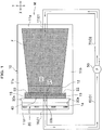
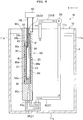
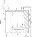
- a plating apparatus M of the first embodiment includes a plating tank 10, an anode member 20, a cathode jig 30, a space 40, and a pump 50.
- the dot hatched area represents a region in which a plating liquid F resides.
- the plating tank 10 is configured to store the plating liquid F as shown in FIGS. 1 and 2 .
- the plating tank 10 is a vessel provided with a bottom 11a, a pair of side walls 11b and 11c facing each other in the orthogonal direction Y, and a pair of side walls 11d and 11e facing each other in the facing direction X.
- the plating tank 10 is shaped in a box vessel having an upper opening, and made of resin.
- the plating liquid F is stored only in a region behind the anode member (i.e., perpendicular wall 12) opposite to the space 40 in the plating tank 10.
- the plating tank 10 is shaped in a rectangular in a plan view and arranged so that the longitudinal direction thereof coincidences with the facing direction X. Note that a shape and a material of the plating tank 10 may be appropriately modified.
- the plating tank 10 is provided with a perpendicular wall 12 projected upward from an inner side of the bottom 11a of the plating tank 10, a first holder 13 detachably holding the anode member 20, a second holder 14 detachably holding the cathode jig 30, a plating communication hole 15 communicating the first holder 13 to the space 40, and a suction hole 16 and a discharge hole 17 through which the plating liquid F passes.
- the perpendicular wall 12 which is a wall unit, is a wall shaped part arranged near the side wall 11d of the plating tank 10. Both sides of the perpendicular wall 12 in the orthogonal direction Y are continuously formed to be integral with internal surfaces of the side walls of 11b and 11c of the plating tank 10 (see FIG. 1 ). An upper side of the perpendicular wall 12 is located at a lower position than a level of the plating liquid F and upper ends of the side walls 11b and 11e. In this construction, the plating liquid F flows over the perpendicular wall 12 into the space 40 as described later.
- the perpendicular wall 12 may be separately formed from the plating tank 10, and subsequently attached to the plating tank 10.
- the first holder 13 is a hole shaped in groove and slit having an upper opening.
- the first holder 13 is formed from the upper end to the lower end of the perpendicular wall 12 and arranged thereon at the closer side to the cathode jig 30.
- the anode member 20 is inserted into the first holder 13 to be held thereon.
- the second holder 14 is a part formed in a concave-convex shape corresponding to the outer shape of the cathode jig 30.
- the cathode jig 30 is inserted into the second holder 14 to be held thereon.
- the second holder 14 sandwiches protrusion parts 30a from the both sides thereof in the facing direction X, the protrusion parts 30a being formed at the ends of the cathode jig 30 and arranged at the closer side to the anode member 20.
- the cathode jig 30 may be held on the perpendicular wall 12, and the anode member 20 may be held on the wall sides 11b and 11c.
- the plating communication hole 15 is a through hole exposing the anode member 20 to the space 40.
- the plating communication hole 15 is formed at the middle part in the longitudinal direction of the perpendicular wall 12.
- the suction hole 16 is a thorough hole to be a part of a suction flow passage C1 through which a plating liquid F sucked from the space by the pump 50 passes.
- the suction hole 16 is formed penetrating the bottom 11a of the plating tank 10 from the upper side to the lateral side of the bottom 11a.
- the suction hole 16 extends from the upper side to the lower side of the bottom 11a, and further extends to one way of the facing direction X.
- One end of the suction hole 16 is opened toward a lower part of the space 40.
- a suction pipe 60 communicating the suction hole 16 to the pump 50 is connected with the other end of the suction hole 16. That is, the suction hole 16 and the suction pipe 60 configure the suction flow passage C1.
- the discharge hole 17 is a thorough hole to be a part of a discharge flow passage C2 through which a plating liquid F discharged by the pump 50 passes.
- the discharge hole 17 is formed penetrating the side wall lie of the plating tank 10 from the outer surface to the inner surface of the side wall 11e.
- One end of the discharge hole 17 is opened toward a region placed behind the anode member 20 opposite to the space 40 in the plating tank 10.
- a discharge pipe 70 communicating the discharge hole 17 to the pump 50 is connected with the other end of the discharge hole 17. That is, the discharge hole 17 and the discharge pipe 70 configure the discharge flow passage C2.
- the anode member 20 is a metallic member having a rectangular and plate shape and arranged inside the plating tank 10.
- the anode member 20 is configured so that a center 21 thereof in the orthogonal direction Y is located at a lower position than both end parts 22 and 23 of the anode member 20 in the orthogonal direction Y.
- the upper end of the center 21 of the anode member 20 is formed horizontal, and located at the same height as the upper end of the perpendicular wall 12.
- Both upper ends of the end parts 22 and 23 of the anode member 20 protrude higher than a level of the plating liquid F.
- the plating liquid F flows into the space 40 only over the center 21 of the anode member 20 as described later.
- both the end parts 22 and 23 are connected to a plus terminal of a power source 80 through a connecting cable H1.
- the cathode jig 30 has a function of a cathode member as well as a function of holding a plating object W.
- the cathode jig 30 and the plating object W are arranged inside the plating tank 10 to face the anode member 20.
- the cathode jig 30 includes a pair of holding members 31 and 32 which hold the plating object W, and an electrode 33 which transmits electricity from the power source 80 to the plating object W via contacting therewith.
- a plating opening 32a is formed horizontally penetrating the holding member 32 arranged beside the space 40.
- the plating opening 32a allows the plating object W to be exposed to the space 40 so that the plating liquid F contacts with the plating object W.
- the electrode 33 includes a contacting unit 33a shaped in a ring contacting with a periphery of the plating object W, and a power source connector 33b shaped in a strip connected to the power source 80.
- the power source connector 33b is inserted into an insertion hole 32b formed inside the holding member 32.
- An upper end of the power source connector 33b is located at a higher position than a level of the plating liquid F.
- the power source connector 33b is connected with a minus terminal of the power source 80 through a connecting cable H2.
- An upper end of the cathode jig 30 is located at a higher position than a level of the plating liquid F, and both ends of the cathode jig 30 in the orthogonal direction Y contact with the side walls 11b and 11c of the plating tank 10 without a gap.
- This construction prevents a plating liquid F, which flows into the space 40 from a region beside the anode member 20 in the plating tank 10, from entering a backside of the cathode jig 30.
- the construction of the cathode jig 30 may be appropriately modified, and a cathode plate may be used instead of the cathode jig 30.
- the space 40 is formed between the anode member 20 and the cathode jig 30 (and the plating object W) to be a flow passage to which the plating liquid F flows from the plating tank 10.
- the space 40 is a narrow space shaped in a slit form having an upper opening. Both sides of the space 40 in the orthogonal direction Y are closed by the side walls 11b and 11c of the plating tank 10.
- the space 40 is formed so that a dimension D1 in the facing direction X is smaller than a dimension D2 in the orthogonal direction Y (i.e., D1 ⁇ D2).
- the dimension D1 in the facing direction X is set in the range from about 1 mm to about 3 mm.
- a flow rate of the plating liquid F flowing through the space 40 is preferably set in the range from about 0.1 m/s to about 3 m/s.
- a flow rate of the plating liquid F depends on the dimension D1 of the space 40 in the facing direction X and a performance of the pump 50. Therefore, the flow rate thereof may be appropriately adjusted by changing the above factors.
- the pump 50 is arranged outside the plating tank 10.
- the pump 50 sucks the plating liquid F from the space 40 and discharges the plating liquid F thus sucked into the plating tank 10.
- the plating apparatus M according to the first embodiment of the present invention is basically configured as mentioned hereinbefore. Next, the movement and effects thereof will be described in detail.
- the plating liquid F in the space 40 is sucked. Associated with the suction, the plating liquid F in the plating tank 10 flows over the perpendicular wall 12 and the center 21 of the anode member 20, thereby to flow into the space 40 from above relative to the space 40.
- both sides of the space 40 in the orthogonal direction Y are closed by the side walls of the plating tank 10.
- this construction prevents the plating liquid F from entering the space 40 through the sides thereof.
- the plating liquid F is stored only in a region behind the anode member 20 opposite to the space 40 in the plating tank 10. Due to this construction, the plating liquid F flows into the space 40 from only one side of the anode member 20 (i.e., via only one way in the facing direction X).
- This construction facilitates the plating liquid F to smoothly flow from the plating tank 10 into the space 40 (i.e., suppressing the interference among flow layers of the plating liquid F as much as possible). Thereby, disruption between the flow layers of the plating liquid F in the space 40 may be prevented.
- the plating liquid F flows into the space 40 from an upper portion to a lower portion thereof.
- the power source 80 is turned on to allow the current to flow through the anode member 20 and the electrode 33, metal ions in the plating liquid F are drawn toward the cathode jig 30, thereby disposed on the plating object W to form a plating layer.
- a plating thickness may be adjusted by appropriately modifying a flow rate of the plating liquid F in the space 40 and a current value of the power source 80.
- the plating liquid F is sucked by the pump 50 from below relative to the space 40, thereby flowing through the suction flow passage C1 toward the pump 50.
- the plating liquid F thus reached the pump 50 is discharged from the pump 50, and subsequently returned through the discharge flow passage C2 to the plating tank 10.
- the plating liquid F flows into the space 40 from above relative to the space 40, and is sucked by the pump 50 from below relative to the space 40. Due to this construction, accordingly, the flow rate of the plating liquid F in the space 40 increases. This facilitates the plating liquid F to be uniformly fed onto the plating object W, resulting in improvement of the uniformity of the plating thickness. Further, in the present embodiment, nozzles and a driving mechanism are not necessary to be provided, which realizes the simplification and downsizing of the plating apparatus, leading to suppression of the costs.
- the plating liquid F in the space 40 is continuously replaced.
- plating burning is prevented from occurring at the anode member 20 and the electrode 33. This suppresses plating defects from occurring. Therefore, fast and uniform growth of a plating layer may be achieved, resulting in improvement of the plating productivity.
- both sides of the space 40 in the orthogonal direction Y are closed by the side walls of the plating tank 10.
- This construction prevents the plating liquid F from entering the space 40 through the sides thereof.
- the dimension D1 of the space 40 in the facing direction X is set in the narrow width of from 1 mm to 30 mm. This construction enables the plating liquid F flows as a laminar flow parallel to the longitudinal direction of the plating object W.
- the plating tank 10 includes the first holder 13 detachably holding the anode member 20, the second holder 14 detachably holding the cathode jig 30. Therefore, the anode member 20 and the cathode jig 30 (i.e., and the plating object W) are easily aligned with the plating tank 10. Further, the anode member 20 and the cathode jig 30 are securely held.
- the space 40 is formed between the anode member 20 and the cathode jig 30 (i.e., and the plating object W), and the plating liquid F flows into the space 40 from above and downward relative to the space 40. Accordingly, even when a small sized pump 50 is used, the flow rate of the plating liquid F may be sufficiently kept higher. Further, the use of the small sized pump 50 may realize further downsizing of the plating apparatus M.
- the plating liquid F is circulated by the pump 50. This circulation allows recycling of the plating liquid F so as to eliminate wastes.
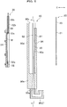
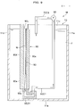
- the plating apparatus M in the second embodiment includes a container bath 90 which houses an anode member 20 and a cathode jig 30, and a general plating tank 10 having no first and second holders 13 and 14, which is different from the first embodiment.
- the anode member 20, the cathode jig 30 and the pump 50 are the same as in the first embodiment. Therefore, the descriptions of those components will be omitted.
- the container bath 90 is arranged inside the plating tank 10, and has a function of housing the anode member 20 and the cathode jig 30.
- the container bath 90 includes a bottom 90a, a pair of lateral sides 90b and 90c facing each other in the orthogonal direction Y, and a pair of lateral sides 90d and 90e facing each other in the facing direction X.
- the container bath 90 is an approximately square cylindrical vessel having an upper opening and made of resin. Note a shape and a material of the container bath 90 may be appropriately modified.
- the container bath 90 includes a first holding unit 91 detachably holding the anode member 20, a second holding unit 92 detachably holding the cathode jig 30, a space 93 formed between the anode member 20 and the cathode jig 30 (i.e., and a plating object W), a plating communication hole 94 communicating the first holding unit 91 with the space 93, and a connector 95 connected to a lower portion (i.e., a downstream end) of the space 93.
- the first holding unit 91 is a hall shaped in a groove and slit-like having an upper opening.
- the first holding unit 91 is formed from the upper end to the lower end of the lateral side 90e, and arranged at the closer side to the cathode jig 30.
- the anode member 20 is inserted into the first holding unit 91 and held therein.
- the upper end of the lateral side 90c is located at a lower position than a level of the plating liquid F and the upper ends of the side walls 11b - 11e. This construction let the plating liquid F flow over the upper end of the lateral side 90e to flow into the space 93, as described later.
- Note the upper end of the center 21 of the anode member 20 is located at the same height as the upper end of the lateral side 90e.
- the second holding unit 92 is a part formed in an uneven shape corresponding to an outer shape of the cathode jig 30.
- the second holding unit 92 is formed on the inner surfaces of the lateral sides 90b and 90c of the container bath 90.
- the cathode jig 30 is inserted into the second holding unit 92 and held.
- the second holding unit 92 sandwiches protrusion parts 30a from the both sides thereof in the facing direction X, the protrusion parts 30a being formed at the ends of the cathode jig 30 and arranged at the closer side to the anode member 20 (see FIG. 7 ).
- the upper end of the lateral side 90d is located at a higher position than a level of the plating liquid F and the upper ends of the side walls 11b - 11e. This construction prevents the plating liquid F from entering the space 93 through the sides of the cathode jig 30.
- the cathode jig 30 may be held by the lateral side 90e, and the anode member 20 may be held by the lateral sides 90b and 90c.
- the space 93 is formed between the anode member 20 and the cathode jig 30 (i.e., and the plating object W) to be a flow passage to which the plating liquid F flows from the plating tank 10.
- the space 93 is a small narrow space shaped in a slit having both upper and lower openings. Both sides of the space 93 in the orthogonal direction Y are closed by the lateral sides 90b and 90c of the container bath 90.
- the space 93 is configured so that a dimension D1 along the facing direction X is smaller than a dimension D2 along the orthogonal direction Y (i.e., D1 ⁇ D2).
- the dimension D1 in the facing direction X is set of, for example, from about 1 mm to about 30 mm.
- a flow rate of the plating liquid F flowing in the space 93 is preferably set at, for example, from about 0.1 m/s to about 3 m/s.
- the flow rate of the plating liquid F depends on the dimension D1 of the space 93 in the facing direction X and the performance of the pump 50. Therefore, the flow rate of the plating liquid F may be adjusted by appropriately modifying those factors.
- a lower part 93a of the space 93 is arranged extending to a lower position than the first and second holding units 91 and 92, and opened toward a bottom 90a of the container 90.
- the lower part 93a of the space 93 is configured so that a width viewed in the longitudinal cross-section along the facing direction X becomes wider as the lower part 93a extends from the upper position to the lower position.
- the lower part 93a of the space 93 is configured so that a width viewed in the longitudinal cross-section along the orthogonal direction Y becomes narrower as the lower part 93a extends from the upper position to the lower position.
- a plating communication hole 94 is a thorough hole used for exposing the anode member 20 to the space 93.
- the plating communication hole 94 is formed at a lower position than the upper end of the lateral side 90e.
- a connector 95 is a member which is a part of a suction flow passage C1 through which the plating liquid F sucked from the space 93 by the pump 50 passes.
- One end of the connector 95 is connected with a lower part 93a of the space 93.
- the other end of the connector 95 is connected with a suction pipe 60 which communicates the connector 95 to the pump 50.
- the suction flow passage C1 is composed of the connector 95 and the suction pipe 60.
- the pump 50 is connected with a discharge pipe 70 working as a discharge flow passage C2 through which the plating liquid F discharged from the pump 50 passes.
- One end of the discharge pipe 70 is opened toward a region behind the anode member 20 opposite to the space 93 in the plating tank 10. That is, in the present embodiment, the discharge flow passage C2 is composed of the discharged pipe 70 alone.
- the plating apparatus M according to the second embodiment of the present invention is basically configured as mentioned above. Next, the movement and effect thereof will be described specifically.
- the plating liquid F in the space 93 is sucked. Associated with the suction, the plating liquid F in the plating tank 10 flows over the upper end of the lateral side 90e and the center 21 of the anode member 20, thereby flowing into the space 93 from above relative to the space 93.
- both sides of the space 93 in the orthogonal direction Y are closed, which prevents the plating liquid F from entering through the sides of the space 93.
- the upper end of the lateral side 90e is located at a lower position than a level of the plating liquid F
- the upper end of the lateral side 90d is located at a higher position than a level of the plating liquid F. Due to this construction, the plating liquid F enters the space 93 only from a region behind the anode member 20 (i.e., only from one way in the facing direction X).
- the above construction allows the plating liquid F to smoothly flow into the space 93 from the plating tank 10 (i.e., preventing the mutual interference among the streamlines of the plating liquid F). Thereby, turbulence of the plating liquid F is prevented in the space 93.
- the plating liquid F flows in the space 93 from top to bottom.
- the power source 80 is turned on to pass a current through the anode member 20 and the electrode 33, metal ions in the plating liquid F are drawn to the cathode jig 30. Thereby, metal is disposed on the plating object W to form a plating layer.
- a plating thickness may be adjusted by appropriately modifying a flow rate of the plating liquid F in the space 93 and a current value of the power source 80.
- the plating liquid F is sucked by the pump 50 from below relative to the space 93, and passes through the suction flow passage C1 toward the pump 50.
- the plating liquid F thus reached the pump 50 is discharged from the pump 50. Then, the plating liquid F returns to the plating tank 10 passing through the discharge flow passage C2.
- the container bath 90 can be used by being housed in a conventional plating tank 10. This provides an advantage of high versatility.
- a plating apparatus M in the third embodiment of the present invention will be described specifically.
- a difference of the third embodiment from the first embodiment is that a plating apparatus M of the present invention is applied to electroless plating. That is, the third embodiment does not include an anode member 20 and a cathode jig 30 or the like, which is different from the first embodiment. Note the same components as in the first embodiment are put with the same references, and overlapped descriptions will be omitted.
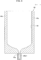
- the plating apparatus M of the third embodiment includes a plating tank 10, a plating object W, a space 40 and a pump 50.
- a perpendicular wall 12 of the plating tank 10 does not include a first holder 13 and a plating communication hole 15, which is different from the first embodiment.
- the plating object W is arranged inside the plating tank 10 to face the perpendicular wall 12.
- the upper end of the plating object W shown in FIG. 8 is located at the same height as a level of the plating liquid F. Note, although illustration is omitted, the upper end of the plating object W may be located at a higher position or a lower position than a level of the plating liquid F. Both ends of the plating object W in the orthogonal direction Y contact with the internal surfaces of side walls 11b and 11c of the plating tank 10 without any gap (Note, only the side wall 11c is shown in FIG. 8 ). Although illustration is omitted, the plating object W is held by, for example, a holder formed in the plating tank 10, in a vertical direction with respect to the plating tank 10.
- the space 40 is formed between the perpendicular wall 12 and the plating object W to work as a flow passage to which the plating liquid F flows from the plating tank 10.
- a flow rate of the plating liquid F flowing through the space 40 is preferably set at about 0.1 m/s - about 3 m/s. More preferably, when electroless plating is carried out as in the present embodiment, a flow rate of the plating liquid F is set at about 0.1 m/s.
- the perpendicular wall 12 may be omitted and the space 40 may be formed between the side wall 11d of the plating tank 10 and the plating object W.
- the space 40 may be formed between the side wall 11e of the plating tank 10 and the plating object W.
- positions of the suction flow passage C1 and the discharge flow passage C2 may be appropriately modified.
- the side walls 11d and 11e of the plating tank 10 are the side walls described in the claims.
- a plating apparatus M according to the fourth embodiment of the present invention will be described specifically.
- a difference of the fourth embodiment from the second embodiment is that a plating apparatus M of the present invention is applied to electroless plating. That is, the fourth embodiment does not include an anode member 20 and a cathode jig 30 or the like, which is different from the second embodiment. Note the same components as in the second embodiment are put with the same references, and overlapped descriptions will be omitted.
- a container bath 90 of the fourth embodiment is arranged inside a plating tank 10, and has a function of housing a plating object W.
- the container bath 90 includes the plating object W, a space 93 formed between a lateral side 90e and the plating object W, and a connector 95 connected to a lower part (i.e., downstream end) of the space 93.
- the container bath 90 of the present invention does not include the first holding unit 91, the second holding unit 92 and the plating communication hole 94, which is different from the second embodiment.
- the plating object W is arranged inside the container bath 90 to face the lateral side 90e.
- the upper end of the plating object W shown in FIG. 9 is located at the same height as a level of a plating liquid F. Although illustration is omitted, the upper end of the plating object W may be located at a higher position of a lower position than a level of the plating liquid F.
- Both ends of the plating object W in the orthogonal direction Y contact with the internal surfaces of the lateral sides 90b and 90c of the container bath 90 without any gap (Note, only the lateral side 90c is shown in FIG. 9 ).
- the plating object W is held, for example, by a holding unit formed in the container bath 90, and arranged in a vertical direction with respect to the container bath 90.
- the space 93 is formed between the lateral side 90e and the plating object W to work as a flow passage to which the plating liquid F flows from the plating tank 10.
- a lower part 93a of the space 93 is arranged extending to a lower position than the lower end of the plating object W, and is opened toward a bottom 90a of the container 90.
- a flow rate of the plating liquid F flowing from the space 93 is preferably set at about 0.1 m/s - about 3 m/s. More preferably, when electroless plating is carried out as in the present embodiment, a flow rate of the plating liquid F is set at about 0.1 m/s.
- the space 93 may be formed between the lateral side 90d of the container bath 90 and the plating object W.
- positions of the suction flow passage C1 and the discharge flow passage C2 are made to be appropriately modified, and the upper end of the lateral end 93d is made to be located at a lower position than a level of the plating liquid F.
- the lateral side 90d of the container bath 90 is the lateral side described in the claims.
- the first and the second embodiments show the construction in which the plating liquid F enters the space 40 or the space 93 from only one side closer to the anode member 20 (i.e., via only one way in the facing direction X).
- the present invention is not limited to the above construction. That is, the plating liquid F may enter the space 40 or the space 93 from only one side closer to the cathode jig 30 (i.e., via only one way in the facing direction X), or the plating liquid F may enter the space 40 or the space 93 from both sides of the anode member 20 and the cathode jig 30 (i.e., via both ways in the facing direction X).
- the third embodiment shows the construction in which the plating liquid F enters the space 40 from only one side closer to the perpendicular wall 12 (i.e., via only one way in the facing direction X).
- the present invention is not limited to the above construction. That is, the plating liquid F may enter the space 40 from only one side closer to the plating object W (i.e., via only the other way in the facing direction X), or the plating liquid F may enter the space 40 from both sides of the perpendicular wall 12 and the plating object W (i.e., via both ways in the facing direction X).
- the fourth embodiment shows the construction in which the plating liquid F enters the space 93 from only one side closer to the lateral side 90e (i.e., via only one way in the facing direction X).
- the present invention is not limited to the above construction. That is, the plating liquid F may enter the space 93 from only one side closer to the lateral side 90d (i.e., via only the other way in the facing direction X), or the plating liquid F may enter the space 93 from both sides of the lateral sides 90d and 90e (i.e., via both ways in the facing direction X).
- the first to the fourth embodiments may have a construction in which an unillustrated stirring rod is provided to be put in or out the space 40 or the space 93 from above relative to the space 40 or 93.
- That stirring rod may be configured to swing along the orthogonal direction Y by, for example, a driving motor, so as to stir the plating liquid F in the space 40.
- a plurality of spatulas for stirring are provided, and the plating liquid F may be stirred by changing the angles of the spatulas.
- the pump 50 circulates the plating liquid F.
- the present invention is not limited to those embodiments.
- Another configuration is applicable in which the plating liquid F thus sucked may be discharged by the pump 50, and a new plating liquid F may be poured into the plating tank 10.
Landscapes
- Chemical & Material Sciences (AREA)
- Chemical Kinetics & Catalysis (AREA)
- Engineering & Computer Science (AREA)
- Materials Engineering (AREA)
- Metallurgy (AREA)
- Organic Chemistry (AREA)
- Electrochemistry (AREA)
- General Chemical & Material Sciences (AREA)
- Mechanical Engineering (AREA)
- Electroplating Methods And Accessories (AREA)
Claims (4)
- Plattierungsvorrichtung (M), umfassend:einen Plattierungstank (10) zum Speichern einer Plattierungsflüssigkeit (F), der Seitenwände (11b-11 e) und einen Boden (11a) aufweist;ein Anodenelement (20), das vertikal in dem Plattierungstank (10) angeordnet ist, wobei ein Plattierungsobjekt (W) vertikal in dem Plattierungstank (10) angeordnet ist, um dem Anodenelement (20) zugewandt zu sein;ein Kathodenelement (30), welches das Plattierungsobjekt (W) berührt; undeine erste Halterung (13), die das Anodenelement (20) lösbar hält;wobei ein Raum (40) zwischen dem Anodenelement (20) und dem Plattierungsobjekt (W) ausgebildet ist, um einem Strömungskanal zu entsprechen, damit die Plattierungsflüssigkeit (F) aus dem Plattierungstank (10) strömen kann; unddas Anodenelement (20) dem Plattierungsobjekt (W) in einer zugewandten Richtung (X) zugewandt ist, wobei eine orthogonale Richtung (Y) zu der zugewandten Richtung (X) orthogonal ist,gekennzeichnet durcheine zweite Halterung (14), die das Plattierungsobjekt (W) lösbar hält;beide Seiten des Raums (40) in der orthogonalen Richtung (Y) sind durch den Plattierungstank (10) verschlossen; undeine senkrechte Wand (12), die von einer Innenseite des Bodens (11a) des Plattierungstanks (10) nach oben projiziert ist, wobei beide Seiten der senkrechten Wand (12) in der orthogonalen Richtung (Y) durchgehend gebildet sind, um mit Innenflächen von Seitenwänden (11b, 11c) des Plattierungstanks (10) einstückig ausgebildet zu sein, und sich eine obere Seite der senkrechten Wand (12) in einer niedrigeren Position befindet als ein Pegel der Plattierungsflüssigkeit (F) und obere Enden der Seitenwände (11b-11e);wodurch es der Plattierungsflüssigkeit (F) ermöglicht wird, über die senkrechte Wand (12) in Bezug auf den Raum (40) von oben in den Raum (40) zu strömen und von einer Pumpe (50) in Bezug auf den Raum (40) von unten angesaugt zu werden.
- Plattierungsvorrichtung (M), umfassend eine Behälterwanne (90) und einen Plattierungstank (10), wobei die Behälterwanne (90) ein Paar von lateralen Seiten (90b, 90c), die einander in einer orthogonalen Richtung (Y) zugewandt sind und ein Paar von lateralen Seiten (90d, 90e) umfasst, die einander in einer zugewandten Richtung zugewandt sind, um eine Plattierungsflüssigkeit (F) zu speichern, wobei die Behälterwanne (90) Folgendes umfasst:ein Anodenelement (20), das vertikal in der Behälterwanne (90) angeordnet ist, wobei ein Plattierungsobjekt (W) in der Behälterwanne (90) vertikal angeordnet ist, um dem Anodenelement (20) zugewandt zu sein;ein Kathodenelement (30), welches das Plattierungsobjekt (W) berührt;das Anodenelement (20) ist dem Plattierungsobjekt (W) in einer zugewandten Richtung (X) zugewandt, und die orthogonale Richtung (Y) ist zu der zugewandten Richtung (X) orthogonal;eine erste Halteeinheit (91), die das Anodenelement (20) lösbar hält, und eine zweite Halteeinheit (92), die das Kathodenelement (30) lösbar hält, undeinen Raum (93), der zwischen dem Anodenelement (20) und dem Plattierungsobjekt (W) ausgebildet ist, um einem Strömungskanal zu entsprechen, damit die Plattierungsflüssigkeit (F) aus dem Plattierungstank (10) strömen kann, der Seitenwände zum Speichern der Plattierungsflüssigkeit (F) aufweist, wobeidie Behälterwanne (90) in dem Plattierungstank (10) angeordnet ist,die erste Halteeinheit (91) von einem oberen Ende zu einem unteren Ende von einem des Paars von lateralen Seiten (90d, 90e) gebildet ist, die einander in der zugewandten Richtung (X) zugewandt sind, und an einer Seite angeordnet ist, die dem Kathodenelement (30) näher ist,sich das obere Ende in einer niedrigeren Position befindet als ein Pegel der Plattierungsflüssigkeit (F) und obere Enden der Seitenwände (11b-11e), und sich ein oberes Ende der anderen lateralen Seite (90d) in einer höheren Position befindet als ein Pegel der Plattierungsflüssigkeit (F) und die oberen Enden der Seitenwände (11b-11e),beide Seiten des Raums (93) in der orthogonalen Richtung (Y) durch die lateralen Seiten der Behälterwanne (90) verschlossen sind,wodurch es der Plattierungsflüssigkeit (F) ermöglicht wird, aus dem Plattierungstank (10) über das obere Ende von einem des Paars von lateralen Seiten, die einander in der zugewandten Richtung zugewandt sind, in Bezug auf den Raum (93) von oben in den Raum (93) zu strömen und von einer Pumpe (50) in Bezug auf den Raum (93) von unten angesaugt zu werden.
- Plattierungsvorrichtung (M), umfassend:einen Plattierungstank (10), umfassend Seitenwände (11b-11e) und einen Boden (11a) zum Speichern einer Plattierungsflüssigkeit (F);eine senkrechte Wand (12), die von einer Innenseite des Bodens (11a) des Plattierungstanks (10) nach oben projiziert ist;ein Plattierungsobjekt (W), das in dem Plattierungstank (10) vertikal angeordnet ist, um der senkrechten Wand (12) zugewandt zu sein und von einer Halterung gehalten wird, die in dem Plattierungstank (10) in einer vertikalen Richtung in Bezug auf den Plattierungstank (10) gebildet ist; wobeiein Raum (40) zwischen der senkrechten Wand (12) und dem Plattierungsobjekt (W) ausgebildet ist, um einem Strömungskanal zu entsprechen, damit die Plattierungsflüssigkeit (F) aus dem Plattierungstank (10) strömen kann, unddas Plattierungsobjekt (W) der senkrechten Wand (12) in einer zugewandten Richtung (X) zugewandt ist und eine orthogonale Richtung (Y) zu der zugewandten Richtung (X) orthogonal ist; wobeibeide Seiten der senkrechten Wand (12) in der orthogonalen Richtung (Y) durchgehend gebildet sind, um mit Innenflächen von Seitenwänden des Plattierungstanks (10) einstückig ausgebildet zu sein, und sich eine obere Seite der senkrechten Wand (12) in einer niedrigeren Position befindet als ein Pegel der Plattierungsflüssigkeit (F) und obere Enden der Seitenwände, undbeide Enden des Plattierungsobjekts (W) in der orthogonalen Richtung (Y) Innenflächen der Seitenwände (11b, 11c) ohne eine Lücke berühren,wodurch es der Plattierungsflüssigkeit (F) ermöglicht wird, über die senkrechte Wand (12) in Bezug auf den Raum (40) von oben in den Raum (40) zu strömen und von einer Pumpe (50) in Bezug auf den Raum (40) von unten angesaugt zu werden.
- Plattierungsvorrichtung (M), umfassend eine Behälterwanne (90) und einen Plattierungstank (10) zum Speichern einer Plattierungsflüssigkeit (F), wobei die Behälterwanne (90) in dem Plattierungstank (10) angeordnet ist, und die Behälterwanne (90) Folgendes umfasst:laterale Seiten (90b, 90c, 90d, 90e); wobeiein Plattierungsobjekt (W) in der Behälterwanne (90) vertikal angeordnet ist, um einer (90e) der lateralen Seiten zugewandt zu sein;das Plattierungsobjekt (W) einer (90e) der lateralen Seiten in einer zugewandten Richtung (X) zugewandt ist, und eine orthogonale Richtung (Y) zu der zugewandten Richtung (X) orthogonal ist; undein Raum (93) zwischen der einen (90e) der lateralen Seiten und dem Plattierungsobjekt (W) ausgebildet ist, um einem Strömungskanal zu entsprechen, damit die Plattierungsflüssigkeit (F) aus dem Plattierungstank (10) strömen kann, wobeibeide Enden des Plattierungsobjekts (W) in der orthogonalen Richtung (Y) Innenflächen der lateralen Seiten (90b, 90c) der Behälterwanne (90) ohne eine Lücke berühren;wodurch es der Plattierungsflüssigkeit (F) ermöglicht wird, über ein oberes Ende der einen (90e) der lateralen Seiten, die dem Plattierungsobjekt (W) zugewandt ist, in Bezug auf den Raum (93) von oben in den Raum (40) zu strömen und von einer Pumpe (50) in Bezug auf den Raum (93) von unten angesaugt zu werden.
Applications Claiming Priority (2)
| Application Number | Priority Date | Filing Date | Title |
|---|---|---|---|
| JP2014098446 | 2014-05-12 | ||
| PCT/JP2015/061726 WO2015174204A1 (ja) | 2014-05-12 | 2015-04-16 | めっき装置及び収容槽 |
Publications (3)
| Publication Number | Publication Date |
|---|---|
| EP3144417A1 EP3144417A1 (de) | 2017-03-22 |
| EP3144417A4 EP3144417A4 (de) | 2017-12-20 |
| EP3144417B1 true EP3144417B1 (de) | 2019-09-18 |
Family
ID=54479748
Family Applications (1)
| Application Number | Title | Priority Date | Filing Date |
|---|---|---|---|
| EP15793615.4A Active EP3144417B1 (de) | 2014-05-12 | 2015-04-16 | Plattierungsvorrichtung und behälterbad |
Country Status (8)
| Country | Link |
|---|---|
| US (1) | US10030313B2 (de) |
| EP (1) | EP3144417B1 (de) |
| JP (1) | JP6552485B2 (de) |
| KR (1) | KR101789080B1 (de) |
| CN (1) | CN105917033B (de) |
| SG (1) | SG11201604287YA (de) |
| TW (1) | TWI568893B (de) |
| WO (1) | WO2015174204A1 (de) |
Families Citing this family (3)
| Publication number | Priority date | Publication date | Assignee | Title |
|---|---|---|---|---|
| JP6472693B2 (ja) * | 2015-03-24 | 2019-02-20 | 株式会社荏原製作所 | 基板処理装置 |
| JP7316908B2 (ja) * | 2019-10-30 | 2023-07-28 | 株式会社荏原製作所 | アノード組立体 |
| CN115874249A (zh) * | 2022-11-30 | 2023-03-31 | 福建华威钜全精工科技有限公司 | 一种汽缸电镀阳极内流道机构 |
Family Cites Families (13)
| Publication number | Priority date | Publication date | Assignee | Title |
|---|---|---|---|---|
| JP4087839B2 (ja) | 1999-03-11 | 2008-05-21 | 株式会社荏原製作所 | めっき装置 |
| JP3939124B2 (ja) | 2001-10-15 | 2007-07-04 | 株式会社荏原製作所 | 配線形成方法 |
| JP2003342783A (ja) | 2002-05-28 | 2003-12-03 | Micronics Japan Co Ltd | メッキ方法及び装置 |
| KR101027489B1 (ko) * | 2002-07-18 | 2011-04-06 | 가부시키가이샤 에바라 세이사꾸쇼 | 도금장치 및 도금방법 |
| WO2004081261A2 (en) | 2003-03-11 | 2004-09-23 | Ebara Corporation | Plating apparatus |
| JP2004339590A (ja) * | 2003-05-19 | 2004-12-02 | Atotech Japan Kk | 表面処理装置 |
| JP3930832B2 (ja) * | 2003-06-06 | 2007-06-13 | 株式会社山本鍍金試験器 | 水槽 |
| JP4553632B2 (ja) * | 2004-05-21 | 2010-09-29 | 株式会社荏原製作所 | 基板めっき方法及び基板めっき装置 |
| CN2839303Y (zh) * | 2005-07-19 | 2006-11-22 | 官锦堃 | 喷流漂浮式电镀槽 |
| JP2009091597A (ja) * | 2007-10-03 | 2009-04-30 | Japan Envirotic Industry Co Ltd | 処理装置 |
| JP2011052241A (ja) | 2009-08-31 | 2011-03-17 | Murata Mfg Co Ltd | めっき装置及びめっき方法 |
| WO2011105072A1 (ja) | 2010-02-24 | 2011-09-01 | 住友ベークライト株式会社 | 基板処理方法および基板処理装置 |
| JP5775436B2 (ja) * | 2011-11-30 | 2015-09-09 | 富士重工業株式会社 | 電着塗装装置 |
-
2015
- 2015-04-16 EP EP15793615.4A patent/EP3144417B1/de active Active
- 2015-04-16 WO PCT/JP2015/061726 patent/WO2015174204A1/ja not_active Ceased
- 2015-04-16 KR KR1020167018073A patent/KR101789080B1/ko not_active Expired - Fee Related
- 2015-04-16 US US15/100,446 patent/US10030313B2/en not_active Expired - Fee Related
- 2015-04-16 JP JP2016519174A patent/JP6552485B2/ja active Active
- 2015-04-16 SG SG11201604287YA patent/SG11201604287YA/en unknown
- 2015-04-16 CN CN201580004879.XA patent/CN105917033B/zh active Active
- 2015-04-30 TW TW104113849A patent/TWI568893B/zh active
Non-Patent Citations (1)
| Title |
|---|
| None * |
Also Published As
| Publication number | Publication date |
|---|---|
| EP3144417A4 (de) | 2017-12-20 |
| EP3144417A1 (de) | 2017-03-22 |
| US10030313B2 (en) | 2018-07-24 |
| JP6552485B2 (ja) | 2019-07-31 |
| JPWO2015174204A1 (ja) | 2017-04-20 |
| KR101789080B1 (ko) | 2017-10-23 |
| CN105917033B (zh) | 2018-01-19 |
| TW201610242A (zh) | 2016-03-16 |
| SG11201604287YA (en) | 2016-07-28 |
| WO2015174204A1 (ja) | 2015-11-19 |
| CN105917033A (zh) | 2016-08-31 |
| TWI568893B (zh) | 2017-02-01 |
| US20160305032A1 (en) | 2016-10-20 |
| KR20160095100A (ko) | 2016-08-10 |
Similar Documents
| Publication | Publication Date | Title |
|---|---|---|
| US9297088B2 (en) | Electroplating method and electroplating apparatus for through-hole | |
| US20190112728A1 (en) | Plating apparatus and plating method | |
| US10030313B2 (en) | Plating apparatus and container bath | |
| EP2746433B1 (de) | Vorrichtung zur vertikalen galvanischen Ablagerung eines Metalls, vorzugsweise Kupfer, auf einem Substrat und zur Aufnahme solch einer Vorrichtung geeigneter Behälter | |
| US6174417B1 (en) | Electroplating machine | |
| KR100864753B1 (ko) | 금속박 전해 제조장치 | |
| US7361225B2 (en) | Liquid tank | |
| TW511130B (en) | A reactor for electrochemically processing a microelectronic workpiece including improved electrode assembly | |
| US6261425B1 (en) | Electroplating machine | |
| CN203419996U (zh) | 电铸设备 | |
| CN218404472U (zh) | 均流器和镀槽 | |
| JP2006299367A (ja) | 電気めっき試験器 | |
| CN111118552A (zh) | 电铸系统和方法 | |
| KR102674416B1 (ko) | 전기도금 장치, 이를 이용한 전기도금 방법 및 이를 이용해 제조된 캐비티필터 | |
| CN203360601U (zh) | 电铸设备 | |
| US7204918B2 (en) | High efficiency plating apparatus and method | |
| JPWO2002079548A1 (ja) | 電解めっき槽 | |
| US20250207291A1 (en) | Anode titanium basket and continuous electroplating apparatus including the same | |
| US20250146165A1 (en) | System for a chemical and/or electrolytic surface treatment of a substrate | |
| CN207891448U (zh) | 用于电镀不同尺寸整板的电镀装置 | |
| CN117107335A (zh) | 电极结构和电化学沉积设备 | |
| JPH11121674A (ja) | 半導体リードフレームのメッキ方法及びその装置 | |
| JPH0499898A (ja) | メッキ装置の陽極構造 | |
| KR20160003043U (ko) | 주화 도금장치 |
Legal Events
| Date | Code | Title | Description |
|---|---|---|---|
| STAA | Information on the status of an ep patent application or granted ep patent |
Free format text: STATUS: THE INTERNATIONAL PUBLICATION HAS BEEN MADE |
|
| PUAI | Public reference made under article 153(3) epc to a published international application that has entered the european phase |
Free format text: ORIGINAL CODE: 0009012 |
|
| STAA | Information on the status of an ep patent application or granted ep patent |
Free format text: STATUS: REQUEST FOR EXAMINATION WAS MADE |
|
| 17P | Request for examination filed |
Effective date: 20161208 |
|
| AK | Designated contracting states |
Kind code of ref document: A1 Designated state(s): AL AT BE BG CH CY CZ DE DK EE ES FI FR GB GR HR HU IE IS IT LI LT LU LV MC MK MT NL NO PL PT RO RS SE SI SK SM TR |
|
| AX | Request for extension of the european patent |
Extension state: BA ME |
|
| DAV | Request for validation of the european patent (deleted) | ||
| DAX | Request for extension of the european patent (deleted) | ||
| A4 | Supplementary search report drawn up and despatched |
Effective date: 20171120 |
|
| RIC1 | Information provided on ipc code assigned before grant |
Ipc: C25D 17/06 20060101ALN20171113BHEP Ipc: C25D 17/10 20060101ALN20171113BHEP Ipc: C25D 17/02 20060101ALI20171113BHEP Ipc: C25D 3/38 20060101ALN20171113BHEP Ipc: C23C 18/16 20060101ALI20171113BHEP Ipc: C25D 17/00 20060101ALI20171113BHEP Ipc: C25D 21/10 20060101ALN20171113BHEP Ipc: C25D 5/08 20060101AFI20171113BHEP |
|
| STAA | Information on the status of an ep patent application or granted ep patent |
Free format text: STATUS: EXAMINATION IS IN PROGRESS |
|
| 17Q | First examination report despatched |
Effective date: 20181212 |
|
| GRAJ | Information related to disapproval of communication of intention to grant by the applicant or resumption of examination proceedings by the epo deleted |
Free format text: ORIGINAL CODE: EPIDOSDIGR1 |
|
| GRAP | Despatch of communication of intention to grant a patent |
Free format text: ORIGINAL CODE: EPIDOSNIGR1 |
|
| RIC1 | Information provided on ipc code assigned before grant |
Ipc: C25D 21/10 20060101ALN20190225BHEP Ipc: C25D 17/00 20060101ALI20190225BHEP Ipc: C25D 17/02 20060101ALI20190225BHEP Ipc: C25D 17/10 20060101ALN20190225BHEP Ipc: C25D 3/38 20060101ALN20190225BHEP Ipc: C23C 18/16 20060101ALI20190225BHEP Ipc: C25D 17/06 20060101ALN20190225BHEP Ipc: C25D 5/08 20060101AFI20190225BHEP |
|
| RIC1 | Information provided on ipc code assigned before grant |
Ipc: C25D 17/06 20060101ALN20190312BHEP Ipc: C25D 5/08 20060101AFI20190312BHEP Ipc: C23C 18/16 20060101ALI20190312BHEP Ipc: C25D 17/10 20060101ALN20190312BHEP Ipc: C25D 17/00 20060101ALI20190312BHEP Ipc: C25D 3/38 20060101ALN20190312BHEP Ipc: C25D 21/10 20060101ALN20190312BHEP Ipc: C25D 17/02 20060101ALI20190312BHEP |
|
| GRAP | Despatch of communication of intention to grant a patent |
Free format text: ORIGINAL CODE: EPIDOSNIGR1 |
|
| STAA | Information on the status of an ep patent application or granted ep patent |
Free format text: STATUS: GRANT OF PATENT IS INTENDED |
|
| RIN1 | Information on inventor provided before grant (corrected) |
Inventor name: YAMAMOTO WATARU Inventor name: HARADA FUMIO Inventor name: KIYOKAWA HAJIME |
|
| INTG | Intention to grant announced |
Effective date: 20190426 |
|
| GRAS | Grant fee paid |
Free format text: ORIGINAL CODE: EPIDOSNIGR3 |
|
| GRAA | (expected) grant |
Free format text: ORIGINAL CODE: 0009210 |
|
| STAA | Information on the status of an ep patent application or granted ep patent |
Free format text: STATUS: THE PATENT HAS BEEN GRANTED |
|
| AK | Designated contracting states |
Kind code of ref document: B1 Designated state(s): AL AT BE BG CH CY CZ DE DK EE ES FI FR GB GR HR HU IE IS IT LI LT LU LV MC MK MT NL NO PL PT RO RS SE SI SK SM TR |
|
| REG | Reference to a national code |
Ref country code: GB Ref legal event code: FG4D |
|
| REG | Reference to a national code |
Ref country code: CH Ref legal event code: EP |
|
| REG | Reference to a national code |
Ref country code: DE Ref legal event code: R096 Ref document number: 602015038337 Country of ref document: DE |
|
| REG | Reference to a national code |
Ref country code: AT Ref legal event code: REF Ref document number: 1181409 Country of ref document: AT Kind code of ref document: T Effective date: 20191015 |
|
| REG | Reference to a national code |
Ref country code: IE Ref legal event code: FG4D |
|
| REG | Reference to a national code |
Ref country code: NL Ref legal event code: MP Effective date: 20190918 |
|
| PG25 | Lapsed in a contracting state [announced via postgrant information from national office to epo] |
Ref country code: LT Free format text: LAPSE BECAUSE OF FAILURE TO SUBMIT A TRANSLATION OF THE DESCRIPTION OR TO PAY THE FEE WITHIN THE PRESCRIBED TIME-LIMIT Effective date: 20190918 Ref country code: FI Free format text: LAPSE BECAUSE OF FAILURE TO SUBMIT A TRANSLATION OF THE DESCRIPTION OR TO PAY THE FEE WITHIN THE PRESCRIBED TIME-LIMIT Effective date: 20190918 Ref country code: NO Free format text: LAPSE BECAUSE OF FAILURE TO SUBMIT A TRANSLATION OF THE DESCRIPTION OR TO PAY THE FEE WITHIN THE PRESCRIBED TIME-LIMIT Effective date: 20191218 Ref country code: BG Free format text: LAPSE BECAUSE OF FAILURE TO SUBMIT A TRANSLATION OF THE DESCRIPTION OR TO PAY THE FEE WITHIN THE PRESCRIBED TIME-LIMIT Effective date: 20191218 Ref country code: SE Free format text: LAPSE BECAUSE OF FAILURE TO SUBMIT A TRANSLATION OF THE DESCRIPTION OR TO PAY THE FEE WITHIN THE PRESCRIBED TIME-LIMIT Effective date: 20190918 Ref country code: HR Free format text: LAPSE BECAUSE OF FAILURE TO SUBMIT A TRANSLATION OF THE DESCRIPTION OR TO PAY THE FEE WITHIN THE PRESCRIBED TIME-LIMIT Effective date: 20190918 |
|
| REG | Reference to a national code |
Ref country code: LT Ref legal event code: MG4D |
|
| PG25 | Lapsed in a contracting state [announced via postgrant information from national office to epo] |
Ref country code: LV Free format text: LAPSE BECAUSE OF FAILURE TO SUBMIT A TRANSLATION OF THE DESCRIPTION OR TO PAY THE FEE WITHIN THE PRESCRIBED TIME-LIMIT Effective date: 20190918 Ref country code: GR Free format text: LAPSE BECAUSE OF FAILURE TO SUBMIT A TRANSLATION OF THE DESCRIPTION OR TO PAY THE FEE WITHIN THE PRESCRIBED TIME-LIMIT Effective date: 20191219 Ref country code: RS Free format text: LAPSE BECAUSE OF FAILURE TO SUBMIT A TRANSLATION OF THE DESCRIPTION OR TO PAY THE FEE WITHIN THE PRESCRIBED TIME-LIMIT Effective date: 20190918 Ref country code: AL Free format text: LAPSE BECAUSE OF FAILURE TO SUBMIT A TRANSLATION OF THE DESCRIPTION OR TO PAY THE FEE WITHIN THE PRESCRIBED TIME-LIMIT Effective date: 20190918 |
|
| REG | Reference to a national code |
Ref country code: AT Ref legal event code: MK05 Ref document number: 1181409 Country of ref document: AT Kind code of ref document: T Effective date: 20190918 |
|
| PG25 | Lapsed in a contracting state [announced via postgrant information from national office to epo] |
Ref country code: IT Free format text: LAPSE BECAUSE OF FAILURE TO SUBMIT A TRANSLATION OF THE DESCRIPTION OR TO PAY THE FEE WITHIN THE PRESCRIBED TIME-LIMIT Effective date: 20190918 Ref country code: ES Free format text: LAPSE BECAUSE OF FAILURE TO SUBMIT A TRANSLATION OF THE DESCRIPTION OR TO PAY THE FEE WITHIN THE PRESCRIBED TIME-LIMIT Effective date: 20190918 Ref country code: NL Free format text: LAPSE BECAUSE OF FAILURE TO SUBMIT A TRANSLATION OF THE DESCRIPTION OR TO PAY THE FEE WITHIN THE PRESCRIBED TIME-LIMIT Effective date: 20190918 Ref country code: RO Free format text: LAPSE BECAUSE OF FAILURE TO SUBMIT A TRANSLATION OF THE DESCRIPTION OR TO PAY THE FEE WITHIN THE PRESCRIBED TIME-LIMIT Effective date: 20190918 Ref country code: EE Free format text: LAPSE BECAUSE OF FAILURE TO SUBMIT A TRANSLATION OF THE DESCRIPTION OR TO PAY THE FEE WITHIN THE PRESCRIBED TIME-LIMIT Effective date: 20190918 Ref country code: PT Free format text: LAPSE BECAUSE OF FAILURE TO SUBMIT A TRANSLATION OF THE DESCRIPTION OR TO PAY THE FEE WITHIN THE PRESCRIBED TIME-LIMIT Effective date: 20200120 Ref country code: AT Free format text: LAPSE BECAUSE OF FAILURE TO SUBMIT A TRANSLATION OF THE DESCRIPTION OR TO PAY THE FEE WITHIN THE PRESCRIBED TIME-LIMIT Effective date: 20190918 Ref country code: PL Free format text: LAPSE BECAUSE OF FAILURE TO SUBMIT A TRANSLATION OF THE DESCRIPTION OR TO PAY THE FEE WITHIN THE PRESCRIBED TIME-LIMIT Effective date: 20190918 |
|
| PG25 | Lapsed in a contracting state [announced via postgrant information from national office to epo] |
Ref country code: SM Free format text: LAPSE BECAUSE OF FAILURE TO SUBMIT A TRANSLATION OF THE DESCRIPTION OR TO PAY THE FEE WITHIN THE PRESCRIBED TIME-LIMIT Effective date: 20190918 Ref country code: SK Free format text: LAPSE BECAUSE OF FAILURE TO SUBMIT A TRANSLATION OF THE DESCRIPTION OR TO PAY THE FEE WITHIN THE PRESCRIBED TIME-LIMIT Effective date: 20190918 Ref country code: CZ Free format text: LAPSE BECAUSE OF FAILURE TO SUBMIT A TRANSLATION OF THE DESCRIPTION OR TO PAY THE FEE WITHIN THE PRESCRIBED TIME-LIMIT Effective date: 20190918 Ref country code: IS Free format text: LAPSE BECAUSE OF FAILURE TO SUBMIT A TRANSLATION OF THE DESCRIPTION OR TO PAY THE FEE WITHIN THE PRESCRIBED TIME-LIMIT Effective date: 20200224 |
|
| REG | Reference to a national code |
Ref country code: DE Ref legal event code: R097 Ref document number: 602015038337 Country of ref document: DE |
|
| PLBE | No opposition filed within time limit |
Free format text: ORIGINAL CODE: 0009261 |
|
| STAA | Information on the status of an ep patent application or granted ep patent |
Free format text: STATUS: NO OPPOSITION FILED WITHIN TIME LIMIT |
|
| PG2D | Information on lapse in contracting state deleted |
Ref country code: IS |
|
| PG25 | Lapsed in a contracting state [announced via postgrant information from national office to epo] |
Ref country code: DK Free format text: LAPSE BECAUSE OF FAILURE TO SUBMIT A TRANSLATION OF THE DESCRIPTION OR TO PAY THE FEE WITHIN THE PRESCRIBED TIME-LIMIT Effective date: 20190918 Ref country code: IS Free format text: LAPSE BECAUSE OF FAILURE TO SUBMIT A TRANSLATION OF THE DESCRIPTION OR TO PAY THE FEE WITHIN THE PRESCRIBED TIME-LIMIT Effective date: 20200119 |
|
| 26N | No opposition filed |
Effective date: 20200619 |
|
| PG25 | Lapsed in a contracting state [announced via postgrant information from national office to epo] |
Ref country code: SI Free format text: LAPSE BECAUSE OF FAILURE TO SUBMIT A TRANSLATION OF THE DESCRIPTION OR TO PAY THE FEE WITHIN THE PRESCRIBED TIME-LIMIT Effective date: 20190918 |
|
| PG25 | Lapsed in a contracting state [announced via postgrant information from national office to epo] |
Ref country code: MC Free format text: LAPSE BECAUSE OF FAILURE TO SUBMIT A TRANSLATION OF THE DESCRIPTION OR TO PAY THE FEE WITHIN THE PRESCRIBED TIME-LIMIT Effective date: 20190918 |
|
| REG | Reference to a national code |
Ref country code: CH Ref legal event code: PL |
|
| PG25 | Lapsed in a contracting state [announced via postgrant information from national office to epo] |
Ref country code: CH Free format text: LAPSE BECAUSE OF NON-PAYMENT OF DUE FEES Effective date: 20200430 Ref country code: LI Free format text: LAPSE BECAUSE OF NON-PAYMENT OF DUE FEES Effective date: 20200430 Ref country code: LU Free format text: LAPSE BECAUSE OF NON-PAYMENT OF DUE FEES Effective date: 20200416 |
|
| REG | Reference to a national code |
Ref country code: BE Ref legal event code: MM Effective date: 20200430 |
|
| PG25 | Lapsed in a contracting state [announced via postgrant information from national office to epo] |
Ref country code: BE Free format text: LAPSE BECAUSE OF NON-PAYMENT OF DUE FEES Effective date: 20200430 |
|
| GBPC | Gb: european patent ceased through non-payment of renewal fee |
Effective date: 20200416 |
|
| PG25 | Lapsed in a contracting state [announced via postgrant information from national office to epo] |
Ref country code: IE Free format text: LAPSE BECAUSE OF NON-PAYMENT OF DUE FEES Effective date: 20200416 Ref country code: GB Free format text: LAPSE BECAUSE OF NON-PAYMENT OF DUE FEES Effective date: 20200416 |
|
| PG25 | Lapsed in a contracting state [announced via postgrant information from national office to epo] |
Ref country code: TR Free format text: LAPSE BECAUSE OF FAILURE TO SUBMIT A TRANSLATION OF THE DESCRIPTION OR TO PAY THE FEE WITHIN THE PRESCRIBED TIME-LIMIT Effective date: 20190918 Ref country code: MT Free format text: LAPSE BECAUSE OF FAILURE TO SUBMIT A TRANSLATION OF THE DESCRIPTION OR TO PAY THE FEE WITHIN THE PRESCRIBED TIME-LIMIT Effective date: 20190918 Ref country code: CY Free format text: LAPSE BECAUSE OF FAILURE TO SUBMIT A TRANSLATION OF THE DESCRIPTION OR TO PAY THE FEE WITHIN THE PRESCRIBED TIME-LIMIT Effective date: 20190918 |
|
| PG25 | Lapsed in a contracting state [announced via postgrant information from national office to epo] |
Ref country code: MK Free format text: LAPSE BECAUSE OF FAILURE TO SUBMIT A TRANSLATION OF THE DESCRIPTION OR TO PAY THE FEE WITHIN THE PRESCRIBED TIME-LIMIT Effective date: 20190918 |
|
| PGFP | Annual fee paid to national office [announced via postgrant information from national office to epo] |
Ref country code: DE Payment date: 20260324 Year of fee payment: 12 |
|
| PGFP | Annual fee paid to national office [announced via postgrant information from national office to epo] |
Ref country code: FR Payment date: 20260402 Year of fee payment: 12 |