EP3144446B1 - Lukendeckel für eine bodentreppeneinrichtung sowie entsprechende bodentreppeneinrichtung - Google Patents
Lukendeckel für eine bodentreppeneinrichtung sowie entsprechende bodentreppeneinrichtung Download PDFInfo
- Publication number
- EP3144446B1 EP3144446B1 EP16183565.7A EP16183565A EP3144446B1 EP 3144446 B1 EP3144446 B1 EP 3144446B1 EP 16183565 A EP16183565 A EP 16183565A EP 3144446 B1 EP3144446 B1 EP 3144446B1
- Authority
- EP
- European Patent Office
- Prior art keywords
- hatch
- hatch cover
- cover
- locking pin
- box
- Prior art date
- Legal status (The legal status is an assumption and is not a legal conclusion. Google has not performed a legal analysis and makes no representation as to the accuracy of the status listed.)
- Active
Links
Images


Classifications
-
- E—FIXED CONSTRUCTIONS
- E04—BUILDING
- E04F—FINISHING WORK ON BUILDINGS, e.g. STAIRS, FLOORS
- E04F11/00—Stairways, ramps, or like structures; Balustrades; Handrails
- E04F11/02—Stairways; Layouts thereof
- E04F11/04—Movable stairways, e.g. of loft ladders which may or may not be concealable or extensible
-
- E—FIXED CONSTRUCTIONS
- E05—LOCKS; KEYS; WINDOW OR DOOR FITTINGS; SAFES
- E05C—BOLTS OR FASTENING DEVICES FOR WINGS, SPECIALLY FOR DOORS OR WINDOWS
- E05C9/00—Arrangements of simultaneously actuated bolts or other securing devices at well-separated positions on the same wing
- E05C9/06—Arrangements of simultaneously actuated bolts or other securing devices at well-separated positions on the same wing with three or more sliding bars
- E05C9/063—Arrangements of simultaneously actuated bolts or other securing devices at well-separated positions on the same wing with three or more sliding bars extending along three or more sides of the wing or frame
Definitions
- the invention relates to a hatch cover for a floor stairway device, which can be pivoted on a hatch box of the floor stairway device.
- the invention further relates to a floor staircase device.
- U1 discloses a hatch cover for a floor stairway device which is pivotally displaceable on a hatch box of the floor stairway device, comprising a fitting which has a fitting gear and a drive rod which can be displaced by means of the fitting gear, and wherein a locking pin is fastened to the drive rod, which in at least one position is attached to a on the hatch box arranged locking part cooperates to fix the hatch cover with respect to the hatch box.
- the floor staircase device serves, for example, to temporarily make a storage room in a building, in particular in a residential building.
- the storage room is, for example, in an attic of the building, and the attic can be an attic or an attic.
- the storage room is directly delimited by a roof of the building.
- the storage space is preferably accessible through its floor, in particular from an underlying space, in particular a living space. In this respect, the storage room is above the living room, in particular immediately above the living room.
- storage room designating the room that is to be accessible via the staircase device from the room referred to as "living room”.
- the "storage room” can also be used as a living room or the “living room” as a storage room.
- the storage room can also be generally referred to as the first room and the living room as the second room.
- the floor staircase device is now arranged in the floor of the storage room or the ceiling of the living room. It has the hatch box, hatch cover and a flight of stairs.
- the hatch box is preferably arranged and fastened in a recess or recess in the floor of the storage room.
- the hatch cover is in turn pivotally mounted on the hatch box.
- the hatch cover is used to at least temporarily separate the storage space from the living space below or to make it optionally accessible.
- the hatch cover is arranged in a first position such that it has a hatch box recess in the hatch box in a first position closes, in particular completely closes, and at least partially, in particular completely, releases in a second position.
- the storage space can be connected to the living space or connected with the hatch cover at least partially open via the hatch box recess.
- the floor staircase is still assigned to the floor staircase. This is arranged in such a way that after opening the hatch cover it is in a position or can at least be brought into a position in which a user of the floor staircase device can get from the living room into the storage room via the floor staircase.
- the floor staircase is attached to the hatch cover so that it can be pivoted together with the hatch box.
- the stairs can be pulled out or folded out. This is particularly the case if the floor height of the living space is so large that the user cannot easily reach the staircase even when the hatch cover is open.
- the floor staircase is available as a folding staircase, in particular with two or three folding segments, as a sliding staircase, in particular with at least two sliding segments, or as a preferably extendable scissor staircase. Other configurations of the floor staircase are of course also possible.
- the hatch cover can, for example, be acted upon by spring force, the spring force being directed in such a way that it urges the hatch cover in the direction of its first position, which can also be referred to as the closed position, or into it.
- the spring force therefore creates a closing force with which the hatch cover is pressed against the hatch case.
- a certain tightness of the floor staircase device is achieved because the hatch cover is forced into the closed position by the spring force, so that it preferably closes tightly with the hatch box or rests against it, so that the hatch box recess is completely overlapped or closed by the hatch cover.
- the tightness of the floor staircase device is usually the better, the more the spring force pushes the hatch cover into its closed position or against the hatch case.
- the operability of the floor stair device is impaired by the stronger spring force because the user first of all the spring force must counteract to deflect the hatch cover from the closed position.
- the support of the user by the spring force is limited to a closing process of the hatch cover, in which it is shifted from the second position, which can also be referred to as the open position, in the direction of the closed position or into the closed position.
- the open position in the direction of the closed position or into the closed position.
- the user has to counteract the spring force.
- a fitting which has a fitting gear and a plurality of connecting rods which can be displaced by means of the fitting mechanism and which are arranged on different sides of the hatch cover, at least two of the connecting rods being operatively connected to one another via a corner deflection, and a locking pin being fastened to at least one of the connecting rods which cooperates in at least one position with a closing part arranged on the hatch box for fixing the hatch cover with respect to the hatch box.
- the hatch cover has the fitting by means of which it can be fixed with respect to the hatch box.
- the hatch cover is therefore not, or at least not only, held in its closed position by means of the spring force explained above with respect to the hatch case. Rather, the fitting is provided for this purpose.
- the fitting has the fitting gear and several drive rods.
- the drive rods can be driven or displaced by means of the fitting gear.
- an actuating element of the hatch cover for example a handle or the like, is operatively connected to the drive rods via the fitting mechanism.
- the drive rods are also displaced.
- the gear mechanism is intended to convert a rotary movement of the actuating element into a linear displacement of the drive rods.
- the fitting mechanism acts directly on at least one of the drive rods for this purpose.
- An active connection of the fitting mechanism can be made via this drive rod another of the drive rods.
- the hardware gearbox is not necessarily in direct operative connection with all drive rods.
- At least two of the connecting rods are operatively connected to one another via the corner deflection, so that they can be arranged on different sides of the hatch cover.
- the drive rods are usually present on one end face or several different end faces of the hatch cover.
- the corner deflection enables a direct operative connection to be established between drive rods which are angled against one another, that is to say do not run parallel to one another.
- the drive rods which are operatively connected to one another via the corner deflection are present at an angle to one another which is greater than 0 ° and less than 180 °. In particular, the drive rods are at an angle of approximately 90 °, in particular exactly 90 °, to one another.
- the drive rods are directly connected to each other via the corner drive. This means that one of the drive rods engages directly on a first side of the corner deflection and another of the drive rods on a second side of the corner deflection opposite the first side.
- the locking pin should now be attached to at least one of the drive rods.
- several locking pins can be attached to the at least one of the drive rods.
- such a locking pin in particular exactly such a locking pin, is attached to several of the drive rods, for example to all of the drive rods.
- a locking pin is fastened to opposing drive rods, which in particular run at least approximately, in particular exactly, parallel to one another.
- these locking pins are at least approximately opposite one another, for example in a specific position of the connecting rods which are operatively connected to one another.
- the striker is assigned to the striker. If several locking pins are provided, such a locking part is of course assigned to each of the locking pins.
- the locking pin interacts with the locking part in at least one position in order to fix the hatch cover with respect to the hatch box.
- the closing part is arranged or fastened to the hatch box. If only one locking pin is discussed below, the explanations can of course be transferred analogously to further locking pins. The explanations therefore preferably apply to each of a plurality of locking pins which are provided on the hatch cover.
- the position in which the locking pin interacts with the locking part for fixing the hatch cover can be referred to as the locking position, for example.
- the locking pin can preferably be arranged either in the locking position or in a release position. While it interacts with the closing part in the locking position for fixing the hatch cover, it releases a shift of the hatch cover in the release position, in particular a shift of the hatch cover from the closed position.
- the locking pin is in engagement in the locking position with the locking part, so it engages in it. In the release position, however, the locking pin is out of engagement with the locking part, and is particularly preferably at a distance from the latter.
- the locking pin is preferably fastened to one of the drive rods, which is spaced apart from the fitting mechanism, that is to say it is only operatively connected to it indirectly via a further one of the drive rods.
- the locking effect achieved by means of the locking pin can be used particularly flexibly.
- the locking pin can be fastened to the drive rod that is directly connected to the fitting gear.
- the described design of the hatch cover or the fitting has the advantage that the closing force with which the hatch cover is pushed in the direction of its closed position or on the hatch case can be selected independently of the spring force. This means that the spring force can be selected regardless of the sealing effect to be achieved.
- the operation of the floor stairway device can be simplified because the spring force - if present - can be selected to match the hatch cover, so that the spring force compensates or almost compensates for the influence of gravity on the hatch cover in at least one position of the hatch cover.
- the spring force is selected such that the hatch cover is held in its closed position by the spring force, but is not pushed against the hatch box when the hatch cover is released for displacement by means of the fitting, i.e. the at least one locking pin is in its release position. This means that the spring force in the closed position corresponds exactly to the influence of gravity on the hatch cover in this position or is at least slightly greater.
- the described hatch cover achieves an excellent tightness of the floor stair device. This applies in particular if at least one locking pin is attached to several of the drive rods.
- a first drive rod selected from the drive rods is operatively connected directly to the fitting gear and, via a corner deflection, to at least one second drive rod selected from the drive rods. Both the first drive rod and the second drive rod are each present as a subset of the drive rods described above.
- the first drive rod is that of the drive rods which is directly connected to the fitting gear or is directly connected to it.
- the second drive rod is operatively connected to the first drive rod via the corner deflection, so that it is only indirectly connected to the fitting gear mechanism, namely via the first drive rod.
- a plurality of second connecting rods can be provided, which are preferably spaced parallel or at least almost parallel to one another on the hatch cover.
- Each of these second drive rods is operatively connected to the first drive rod via a corner drive.
- the second drive rod or the plurality of second drive rods can be driven by means of the fitting mechanism via the first drive rod.
- the first drive rod is designed without a locking pin.
- no locking pin is arranged or attached to the first drive rod.
- a locking element is present on the fitting gear, for example a locking hook.
- the locking element is, for example, in operative connection with the actuating element of the hatch cover, in particular directly or via the fitting gear.
- it can be provided that it is rotatably mounted on the hatch cover, so that when the actuating element rotates, the locking element describes a corresponding rotational movement.
- the locking element can be in the locking position and the release position analogous to the locking pin.
- the locking position In the locking position, it interacts with a locking counter-element of the hatch box to secure the hatch cover with respect to the To fix hatch box.
- the locking element In the release position, however, the locking element is out of engagement with the locking counter-element, so that the hatch cover is released for displacement with respect to the hatch box.
- the locking element is preferably present in its locking position when this is also the case for the locking pin. The same applies to the release position. To this extent, the locking effect of the hatch cover can be further improved with the aid of the locking element.
- the at least one second drive rod has the at least one locking pin, in particular a plurality of locking pins spaced apart from one another. While it can of course be provided that the second drive rod has exactly one locking pin, a plurality of locking pins spaced apart from one another are preferably provided.
- the distance between the locking pins present on the drive rod corresponds, for example, to the length of a section of the drive rod divided by the number of locking pins on this drive rod reduced by one.
- the length of the section is preferably at least 50%, at least 60%, at least 70%, at least 75%, at least 80%, at least 90% or at least 95% of the total length of the drive rod.
- the total length of the drive rod corresponds in particular to the dimensions of the drive rod in the direction in which it has its largest dimensions.
- the second drive rod overlaps the side of the hatch cover on which it is arranged to at least 50%, at least 60%, at least 70%, at least 75%, at least 80% or at least 90% ,
- the second drive rod is arranged on one side or end face of the hatch cover. Its longitudinal central axis preferably points in the direction of the greatest extent of this end face of the hatch cover. The further the second drive rod overlaps the side of the hatch cover, the more flexibly the closing force achieved by means of the locking pin can be positioned.
- the locking pin is preferably part of a center lock, so that it is arranged approximately centrally in the direction in which the front side of the hatch cover has its largest dimensions, for example between 40% and 60% based on the dimensions explained above, based on one of the Ends of the face.
- the second drive rod completely or at least almost completely overlaps the side of the hatch cover, so that a third drive rod opposite the first drive rod can be arranged on the hatch cover, which has a corner deflection with the second drive rod or at least one of the second Connecting rods, is connected.
- a closing force can also be realized on a side of the hatch cover facing away from the fitting gear mechanism or the first drive rod, so that the tightness of the floor stair device is further improved.
- a preferred further embodiment of the invention provides a multilayer structure of the hatch cover with a core and at least one cover layer, in particular on the living room side or hatch box side.
- the hatch cover is constructed in multiple layers and has the core and the at least one cover layer.
- the core is preferably arranged between two cover layers, one of the cover layers being arranged on the living room side and the other of the cover layers on the hatch box side or storage room side.
- the respective cover layer preferably completely overlaps the core on one side in each case. This means that the cover layer immediately adjoins all end faces of the hatch cover, but does not overlap it, but leaves it free.
- the cover layer is preferably designed as a visible layer, ie is visible from the living room or the storage room by the user of the floor staircase device.
- the cover layer can, for example, be in the form of a lacquer or a foil.
- the cover layer can also be in the form of a cover element, for example a wooden element or a plastic element, it being possible for the cover element to be lacquered or foiled.
- a film made of a plastic, in particular a thermoplastic is used, particularly preferably a PVC film (PVC: polyvinyl chloride).
- the core consists of a carrier element and an insulating body, the carrier element enclosing the insulating body and being fastened to the cover layer, in particular to two opposite cover layers.
- the carrier element can form a frame for the insulating body.
- the carrier element encompasses the insulating body at least in the Cut seen completely.
- the carrier element can have at least one strut which extends through the insulating body. The strut is preferably connected on both sides to the carrier element or further struts of the carrier element.
- the carrier element lies directly on the cover layer, preferably on two opposite cover layers, and is particularly preferably attached to the latter.
- the attachment can be designed in any manner, preference is given to a cohesive attachment, in particular by gluing.
- the insulating body can only be inserted into the carrier element and between the cover layers. It is held within the hatch cover by the carrier element and the cover layers, in particular, cannot be displaced.
- the insulating body like the carrier element, preferably lies directly on the cover layer or the two opposite cover layers.
- the insulating body is completely surrounded by the carrier element in all directions, so that the insulating body is present in the carrier element.
- the cover layer or the cover layers are arranged spaced apart from the insulating body, in particular they are kept spaced apart from the insulating body by the carrier element.
- the carrier element is preferably made of a stiffer material than the insulating body.
- the material of the insulating body preferably has a lower thermal conductivity, so that thermal insulation of the hatch cover or the floor stair device is realized by means of the insulating body.
- the carrier element consists of a foam, in particular a closed-cell foam or an integral foam.
- the foam is in particular a foamed plastic, the plastic being present, for example, as a thermoplastic or as a thermoset.
- the foam is preferably in the form of the closed-cell foam or the integral foam.
- the closed-cell foam is characterized by the fact that it has a large number of cells which are completely separated from one another.
- the integral foam on the other hand, has a closed outer skin and a cell nucleus within which the cells are at least partially connected to one another. This means that the density of the integral foam decreases from the outer skin towards the cell nucleus.
- the carrier element is made of foamed polyester consists.
- the polyester is preferably thermoplastic and can, for example, have a density between 100 kg / m 3 and 150 kg / m 3 .
- the insulating body has a lower thermal conductivity than the carrier element, in particular made of polystyrene or polyurethane. Due to the lower thermal conductivity of the insulating body compared to the carrier element, a particularly good insulating effect can be achieved, as already explained above.
- polystyrene or polyurethane is used as the material for the insulating body, in particular in foamed form.
- a preferred further embodiment of the invention provides that the fitting is arranged on the core, in particular on the carrier element.
- the fitting lies on the core at least in some areas. Additionally or alternatively, it is attached to the core, in particular exclusively to the core. This means that the fitting does not abut the cover layer, but rather is arranged at a distance from it.
- the drive rods are slidably supported on the core, in particular they are slidably supported on the core.
- an actuating element of the hatch cover is operatively connected to the fitting gear.
- the actuating element has an actuating shaft which is positively connected to the fitting gear, in particular engages positively in an actuating shaft receptacle of the fitting gear.
- the actuating shaft has, for example, an external polygon, while the actuating shaft receptacle is designed as an internal polygon.
- a preferred further embodiment of the invention provides that the cover layer consists of a material that has a higher rigidity than a material of the core.
- the cover layer should consist of a material which is different from the material from which the core is made, in particular which has a higher rigidity. This is achieved, for example, if the cover layer is in the form of the cover element or forms part of the cover element.
- the cover element and thus the cover layer can be made of wood or plastic, for example.
- the cover element or the cover layer can additionally be painted and / or foiled or in some other way and coated way. For the foiling, for example, the PVC film already mentioned above is used.
- the hatch cover in particular the cover layer, has a fungicidal coating.
- the fungicidal coating is preferably designed in such a way that the formation of molds or their spores on the hatch cover is prevented.
- the storage room and the living room, between which the floor staircase device is located often have different temperatures. For example, the temperature in the particularly unheated storage room is lower than in the living room, which can be heated. Due to the temperature differences, moisture can precipitate on or on the hatch cover. This favors the establishment of mold. For this reason, the fungicidal coating is provided on the hatch cover, for example on the cover layer. Additionally or alternatively, the fungicidal coating can of course also be present on the end faces of the hatch cover, that is to say for example on the core, in particular on the carrier element.
- a seal is provided, in particular in contact with the cover layer and / or in the circumferential direction, which, when the hatch cover is closed, lies sealingly against the hatch case.
- the seal serves to seal the storage space from the living space in terms of flow.
- the seal lies in a fluid-tight manner on the hatch case. The interruption of the flow connection between the storage room and the living room achieved in this way results in particularly good insulation of the floor staircase device.
- the seal is particularly preferably provided continuously in the circumferential direction and is in this respect in the form of a sealing ring.
- the seal preferably completely surrounds the hatch box recess of the hatch box in the circumferential direction.
- the seal can rest on the core and / or the cover layer, preferably also continuously. Accordingly, when the hatch cover is closed, the seal rests on the one hand on the core and / or the cover layer and on the other hand on the hatch case.
- the seal can be attached to the hatch cover as desired. It is particularly preferably attached to the cover layer and / or the core, in particular to the carrier element.
- the cover layer, the core or the carrier element has a seal receptacle in which the seal partially engages and is held in it, preferably non-positively and / or positively.
- the invention further relates to a floor stairway device with a hatch cover according to the above statements, which is pivotally mounted on a hatch box of the floor stairway device.
- the hatch cover has a fitting which has a fitting gear as well as a plurality of connecting rods which can be displaced by means of the fitting mechanism and which are arranged on different sides of the hatch cover, at least two of the connecting rods being operatively connected to one another via a corner deflection, and with at least one the connecting rods are fastened with a locking pin which, in at least one position, interacts with a closing part arranged on the hatch box for fixing the hatch cover with respect to the hatch box.
- the floor staircase device usually has the floor staircase which is attached to the hatch cover and / or the hatch box. Access from the living room to the storage room or vice versa can be established via the hatch box recess in the hatch box, which can be optionally locked or unlocked by means of the hatch cover, and the floor staircase.
- the locking part has a locking pin receptacle with an inlet slope that extends over at least 25%, at least 50% or at least 75% of the locking pin receptacle with respect to a longitudinal extent of the locking pin receptacle.
- the locking part has the locking pin receptacle, in which the locking pin engages in its locking position. In its release position, however, the locking pin is present outside the locking pin receptacle, preferably directly outside the locking pin receptacle. When the locking pin is displaced from the release position in the direction of its locking position or into this, the locking pin enters the locking pin receptacle and subsequently lies against the entry slope.
- the inlet slope is designed such that the hatch cover is pushed into its closed position when the locking pin is displaced in the direction of its locking position.
- the closing force with which the hatch cover is pushed in the direction of the closed position is the greater, the further the locking pin progresses on the inlet slope, that is, the further the locking pin is displaced in the direction of the locking position.
- the inlet slope is now designed in such a way that it not only enables or facilitates entry of the locking pin into the locking pin receptacle. Rather, the displacement of the locking pin in the direction of the locking position should bring about a preferably constant increase in the closing force.
- the inlet slope extends in relation to the longitudinal extent of the locking pin receptacle, starting from an entry opening or opening of the locking pin receptacle through which the locking pin enters the locking pin receptacle, over at least 25%, at least 50% or at least 75% of the locking pin receptacle.
- a holding area of the locking pin receptacle can follow the inlet slope in the direction facing away from the entry opening, which is essentially straight, so that the closing force of the hatch cover in its closed position is essentially independent of the position of the locking pin in the holding area.
- the Figure 1 shows a representation of a floor staircase device 1, for example for temporarily releasing or closing a transition from a living room a storage room or vice versa is provided.
- the floor stairway device 1 has a hatch box 2 on which a hatch cover 3 is pivotally mounted. In the closed position shown here, the hatch cover 3 lies against the hatch case 2, in particular continuously in the circumferential direction.
- the floor staircase device 1 has a floor staircase 4, which in the embodiment shown here consists of several floor staircase segments 5, 6 and 7. These are pivotally attached to one another and to the hatch box 2 and / or the hatch cover 3.
- the floor staircase 4 shown here can be folded out to this extent.
- the floor staircase 4 can of course also be provided in an alternative embodiment.
- the floor staircase 4 can be pulled out in such a way.
- the hatch box 2 is arranged and fastened, for example, in a recess in a floor of the storage room or a ceiling of the living room. It encompasses a hatch-box recess 8 or forms the hatch-box recess 8, wherein the hatch-box recess 8 can optionally be released or closed by means of the hatch cover 3.
- the Figure 2 shows a further representation of the floor stairway device 1, wherein the hatch box 2 described above is not shown. It is clear that the floor staircase 4 is attached to the hatch box 2 and / or the hatch cover 3 by means of a swivel mechanism 9. As already explained above, however, other configurations of the staircase 4 are also possible.
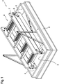
- the hatch cover 3 is preferably constructed in several layers and has a core 10 and cover layers 11 and 12.
- the cover layer 11 is arranged, for example, on the storage room side or hatch box side and the cover layer 12 on the living room side.
- the cover layers 11 and 12 preferably cover the core 10 over their entire surface, that is to say they directly adjoin the front side or side surfaces of the hatch cover 3, which are formed by the core 10.
- the cover layers 11 and 12 each consist of wood and, in this respect, are present as wooden panels each forming a cover element.
- the wooden panels can in turn be provided with a further coating, for example a lacquer or a foil, in particular made of PVC film.
- the floor staircase 4 or the swivel mechanism 9 is fastened to the hatch cover 3 by means of a fastening element 13, the swivel mechanism 9 acting on the fastening element 13 via a lever arm 13 '.
- the fastening element 13 or the swivel mechanism 9 is also connected to the floor staircase 4 via an intermediate piece 14.
- the intermediate piece 14 is designed, for example, as a profiled tube, preferably the fastening element 13, which is designed, for example, as a fastening angle, is fastened directly to the hatch cover 3, in particular the cover layer 11, or lies there.
- the hatch cover 3 has a fitting 15 which has a fitting gear 16 and a plurality of drive rods 17, 18 and 19.
- An actuating element not shown here, for example an actuating handle, can be operatively connected to the drive rods 17, 18 and 19 via the fitting gear 16.
- a recess 20 can be seen, through which the handle or an actuating element shaft of the handle can be brought into operative connection with the fitting gear 16.
- the fitting gear 16 is preferably designed such that it converts a rotary movement of the actuating element into a linear displacement of the drive rods 17, 18 and 19.
- the drive rod 17 is arranged in direct operative connection with the fitting gear 16.
- the drive rod 17 is also referred to below as the first drive rod.
- the drive rods 18 and 19, which can also be referred to as second drive rods 18 and 19, are only indirectly operatively connected to the fitting gear 16, namely via the first drive rod 17. It can be clearly seen that the drive rods 17, 18 and 19 have different Sides of the hatch cover 3 are arranged.
- the second drive rods 18 and 19 are each operatively connected to the first drive rod 17 via a corner deflection 21 and 22, respectively. A displacement of the drive rod 17 is also impressed on the drive rods 18 and 19 via the corner deflections 21 and 22.
- the drive rod 17 is preferably designed without a locking pin
- at least one locking pin in the exemplary embodiment shown here two locking pins 23 and 24, are fastened to the driving rod 18.
- the locking pins 23 and 24 are spaced from each other.
- the drive rod 18 overlaps the side of the hatch cover 3 on which it is arranged to at least 50%.
- the locking pins 23 and 24 are fastened to opposite ends of the drive rod 18, that is to say they have a distance which, based on the largest dimensions of the side of the hatch cover 3 on which the drive rod 18 is present, is at least 40%, at least 45% or at least 50% is.
- the locking pin 24 can be part of a center lock.
- the drive rod 19 is on the side of the hatch cover 3 opposite the drive rod 18. It is arranged parallel to the drive rod 18 and in particular can be displaced linearly parallel to the latter.
- the drive rod 19 also has two locking pins 25 and 26 (not visible here), which are arranged analogously to the locking pins 23 and 24.
- the fitting 15, in particular the connecting rods 17, 18 and 19, are arranged on the hatch cover 3 at a distance from the cover layers 11 and 12. In particular, they are arranged on the core 10 or rest against it. They are particularly preferably fastened to the core 10, in particular mounted such that they can be moved.
- each drive rod 17, 18 and 19 is preferably assigned a cover rail 27, 28 and 29, respectively, which covers, in particular completely, covers the respective drive rod 17, 18 and 19, respectively.
- the drive rods 17, 18 and 19 are arranged in drive rod receptacles 30, not shown here, of the hatch cover 3, in particular of the core 10, and overlapped by the cover rails 27, 28, 29.
- the cover rails 27, 28 and 29 close off or overlap the respective drive rod receptacle 30.
- the cover rails 27, 28 and 29 are purely optional and serve above all to improve the visual impression of the floor staircase device 1.
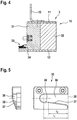
- the Figure 4 shows a sectional view through a region of the hatch cover 3.
- the core 10 is configured in several parts and consists of a carrier element 31 and an insulating body 32.
- the carrier element 31 preferably completely surrounds the insulating body 32, in particular at least in a plane lying parallel to the cover layers 11 and 12.
- the cover layers 11 and 12 preferably each abut the carrier element 31 and are fastened to it, preferably on opposite sides.
- the insulating body 32 also lies against both the cover layer 11 and the cover layer 12. To this extent, the insulating body 32 is enclosed between the cover layers 11 and 12 and the carrier element 31 and held there.
- the fastening element 13 mentioned above is fastened to the cover layer 11 in such a way that it is present in the region of the carrier element 31.
- the carrier element 31 preferably consists of a material which has a higher rigidity than a material of the insulating body 32.
- the fastening element 13 can accordingly can be reliably fastened to the hatch cover 3 in the region of the carrier element 31, for example by means of at least one screw engaging in the carrier element 31.
- the drive rod receptacle 30 is formed in the core 10, in particular in the carrier element 31, preferably completely.
- the drive rod receptacle 30 is arranged spaced from the cover layers 11 and 12.
- a seal 33 is provided which is fastened to the hatch cover 3, in particular to the core 10, particularly preferably to the carrier element 31.
- the seal 33 engages, for example, in a seal receptacle 34 a, which is formed in the carrier element 31, in particular at a distance from the cover layers 11 and 12.
- the seal 33 surrounds the hatch cover 3 preferably completely in the circumferential direction and is present as a sealing ring. If the hatch cover 3 is in its closed position, the seal 33 should lie sealingly on the hatch case 2, in particular thus on the one hand rest against the hatch case 2 and on the other hand against the hatch cover 3.
- the Figure 5 shows a closing part 35, which is arranged and fastened to the hatch case 2, in different views.
- the locking part 35 is intended to cooperate with one of the locking pins 23, 24, 25 and 26 for fixing the hatch cover 3 with respect to the hatch case 2.
- the locking part 35 has a locking pin receptacle 36 which has an inlet slope 37.
- the locking part 35 is arranged on the hatch case 2 such that the respective locking pin 23, 24, 25 or 26 can enter the locking pin receptacle 36 through an entry opening 38. There he comes into contact with the inlet slope 37.
- the inlet slope 37 preferably extends over the distance 12 which corresponds to at least 25%, at least 50% or at least 75% of the longitudinal extent l 1 of the locking pin receptacle 36.
- a holding area 39 can adjoin the inlet slope 37, in particular directly. This holding area 39 runs straight, so that the closing force caused by the locking pin 23, 24, 25 or 26 on the hatch cover 3 in the direction of the hatch box 2 is independent of the position of the locking pin in the holding area 39.
- the floor staircase device 1 described can be provided with a spring element which causes a spring force on the hatch cover 3, which is directed in the direction of its closed position.
- a spring force can be exerted on the hatch cover 3, which counteracts the influence of gravity thereon.
- the spring force in at least one position of the hatch cover 3, for example the closed position is as large as or slightly larger than the force on the hatch cover 3 caused by the influence of gravity, so that this is compensated for by the spring force in the at least one position.
Landscapes
- Engineering & Computer Science (AREA)
- Architecture (AREA)
- Civil Engineering (AREA)
- Structural Engineering (AREA)
- Mechanical Engineering (AREA)
- Ladders (AREA)
- Building Environments (AREA)
Priority Applications (1)
| Application Number | Priority Date | Filing Date | Title |
|---|---|---|---|
| PL16183565T PL3144446T3 (pl) | 2015-09-18 | 2016-08-10 | Pokrywa luku dla urządzenia schodów strychowych, jak też odpowiednie urządzenie schodów strychowych |
Applications Claiming Priority (1)
| Application Number | Priority Date | Filing Date | Title |
|---|---|---|---|
| DE102015217998.2A DE102015217998A1 (de) | 2015-09-18 | 2015-09-18 | Lukendeckel für eine Bodentreppeneinrichtung sowie entsprechende Bodentreppeneinrichtung |
Publications (2)
| Publication Number | Publication Date |
|---|---|
| EP3144446A1 EP3144446A1 (de) | 2017-03-22 |
| EP3144446B1 true EP3144446B1 (de) | 2020-01-15 |
Family
ID=56686666
Family Applications (1)
| Application Number | Title | Priority Date | Filing Date |
|---|---|---|---|
| EP16183565.7A Active EP3144446B1 (de) | 2015-09-18 | 2016-08-10 | Lukendeckel für eine bodentreppeneinrichtung sowie entsprechende bodentreppeneinrichtung |
Country Status (4)
| Country | Link |
|---|---|
| EP (1) | EP3144446B1 (da) |
| DE (1) | DE102015217998A1 (da) |
| DK (1) | DK3144446T3 (da) |
| PL (1) | PL3144446T3 (da) |
Families Citing this family (2)
| Publication number | Priority date | Publication date | Assignee | Title |
|---|---|---|---|---|
| PL440751A1 (pl) | 2022-03-24 | 2023-09-25 | Fakro Pp Spółka Z Ograniczoną Odpowiedzialnością | Zamek konstrukcji skrzynkowej |
| PL440747A1 (pl) * | 2022-03-24 | 2023-09-25 | Fakro Pp Spółka Z Ograniczoną Odpowiedzialnością | Schody strychowe z belką podporową |
Family Cites Families (8)
| Publication number | Priority date | Publication date | Assignee | Title |
|---|---|---|---|---|
| DE1737331U (de) * | 1956-10-26 | 1957-01-03 | Frankfurter Union Ges Schulthe | Getriebe fuer fenster- oder tuerenverschluesse. |
| DE7703539U1 (de) * | 1977-02-08 | 1977-05-12 | Fa. Theodor Dahlmann, 5760 Arnsberg | Lukendeckel |
| US4299059A (en) * | 1980-03-10 | 1981-11-10 | Cardinal Industries, Inc. | Thermally insulated, fire resistant attic door |
| SU1092087A1 (ru) * | 1982-11-18 | 1984-05-15 | Предприятие П/Я А-3780 | Устройство дл задраивани секции закрыти |
| DE202004013051U1 (de) * | 2004-08-19 | 2004-10-14 | Henke Treppen Vertriebs Gmbh | Lukendeckel mit Verschlussvorrichtung |
| NL2001996C (nl) * | 2008-09-19 | 2010-03-22 | Newthex Ned B V | Vergrendelingselement en vergrendelingssysteem voor een scheepsdeur, scheepsraam of scheepsluik. |
| PL233210B1 (pl) * | 2009-03-27 | 2019-09-30 | Fakro Pp Spolka Z Ograniczona Odpowiedzialnoscia | Strychowe schody nożycowe |
| PL224169B1 (pl) * | 2011-01-11 | 2016-11-30 | Fakro Pp Spółka Z Ograniczoną Odpowiedzialnością | Zamknięcie ogniochronne otworu w przegrodzie budowlanej, zwłaszcza otworu ze schodami składanymi |
-
2015
- 2015-09-18 DE DE102015217998.2A patent/DE102015217998A1/de not_active Ceased
-
2016
- 2016-08-10 EP EP16183565.7A patent/EP3144446B1/de active Active
- 2016-08-10 PL PL16183565T patent/PL3144446T3/pl unknown
- 2016-08-10 DK DK16183565.7T patent/DK3144446T3/da active
Non-Patent Citations (1)
| Title |
|---|
| None * |
Also Published As
| Publication number | Publication date |
|---|---|
| EP3144446A1 (de) | 2017-03-22 |
| DK3144446T3 (da) | 2020-04-14 |
| DE102015217998A1 (de) | 2017-03-23 |
| PL3144446T3 (pl) | 2020-07-13 |
Similar Documents
| Publication | Publication Date | Title |
|---|---|---|
| DE202018105095U1 (de) | Tür- und Treppenschutzgitter mit ausrollbarer Trennwand | |
| EP1709270B1 (de) | Klipsbefestigung für die montage von beschlageinrichtungen, wie verschlüsse, scharnierteile, griffe in durchbrüchen in einer dünnen wand | |
| EP2236359B1 (de) | Sanitärmodul und Sanitärsystem, insbesondere eines Fahrzeugs | |
| EP0422678B1 (de) | Gepäckbox | |
| DE2327100A1 (de) | Scharnier, insbesondere moebelscharnier | |
| DE3600211C1 (de) | Fenster- und Tuerbeschlag | |
| EP2025822A2 (de) | Rahmenkonstruktion | |
| EP3144446A1 (de) | Lukendeckel für eine bodentreppeneinrichtung sowie entsprechende bodentreppeneinrichtung | |
| EP3098357B1 (de) | Betätigungsvorrichtung für ein ablaufventil eines spülkastens | |
| DE102013103042A1 (de) | Verfahrbares Wandelement | |
| WO2019068881A2 (de) | Automatisches türsystem, insbesondere in form einer schiebetür oder einer teleskopschiebetür oder einer falttür | |
| EP2252758B1 (de) | Kunststoff-Rollladenkasten sowie Profilsystem für einen solchen Rollladenkasten | |
| EP2787133B1 (de) | Sanitäreinrichtungen | |
| EP2682932B1 (de) | Klappaufsteller für die Präsentation einer Anzeigefläche | |
| EP2476814B1 (de) | Dachbodentreppe | |
| DE202008015581U1 (de) | Bauelement für Fensteröffnungen | |
| EP2311347B1 (de) | Verschlusselement zum Verschließen eines Spaltes zwischen Einbaugerät und Möbelumbau | |
| DE2518318A1 (de) | Verriegelungsvorrichtung | |
| EP0606877B1 (de) | Beschlag für ein eine Falle und einen Riegel aufweisendes Schloss | |
| DE102007007252A1 (de) | Schließanordnung für einen kastenförmigen Fahrzeugaufbau | |
| CH713012A1 (de) | Türdrücker. | |
| EP3871575A1 (de) | Scharnier | |
| EP2853643A1 (de) | Anschlusskörper für eine sanitäre Unterputzarmatur | |
| EP3299531B1 (de) | Deckenplatte einer unterdecke mit werkzeuglos betätigbarem verriegelungselement | |
| DE2540410A1 (de) | Gewaechshausdach |
Legal Events
| Date | Code | Title | Description |
|---|---|---|---|
| PUAI | Public reference made under article 153(3) epc to a published international application that has entered the european phase |
Free format text: ORIGINAL CODE: 0009012 |
|
| STAA | Information on the status of an ep patent application or granted ep patent |
Free format text: STATUS: THE APPLICATION HAS BEEN PUBLISHED |
|
| AK | Designated contracting states |
Kind code of ref document: A1 Designated state(s): AL AT BE BG CH CY CZ DE DK EE ES FI FR GB GR HR HU IE IS IT LI LT LU LV MC MK MT NL NO PL PT RO RS SE SI SK SM TR |
|
| AX | Request for extension of the european patent |
Extension state: BA ME |
|
| STAA | Information on the status of an ep patent application or granted ep patent |
Free format text: STATUS: REQUEST FOR EXAMINATION WAS MADE |
|
| 17P | Request for examination filed |
Effective date: 20170922 |
|
| RBV | Designated contracting states (corrected) |
Designated state(s): AL AT BE BG CH CY CZ DE DK EE ES FI FR GB GR HR HU IE IS IT LI LT LU LV MC MK MT NL NO PL PT RO RS SE SI SK SM TR |
|
| GRAP | Despatch of communication of intention to grant a patent |
Free format text: ORIGINAL CODE: EPIDOSNIGR1 |
|
| STAA | Information on the status of an ep patent application or granted ep patent |
Free format text: STATUS: GRANT OF PATENT IS INTENDED |
|
| RIC1 | Information provided on ipc code assigned before grant |
Ipc: E05C 9/06 20060101ALI20190603BHEP Ipc: E04F 11/04 20060101AFI20190603BHEP Ipc: E05C 9/00 20060101ALI20190603BHEP |
|
| INTG | Intention to grant announced |
Effective date: 20190705 |
|
| GRAS | Grant fee paid |
Free format text: ORIGINAL CODE: EPIDOSNIGR3 |
|
| GRAA | (expected) grant |
Free format text: ORIGINAL CODE: 0009210 |
|
| STAA | Information on the status of an ep patent application or granted ep patent |
Free format text: STATUS: THE PATENT HAS BEEN GRANTED |
|
| RAP1 | Party data changed (applicant data changed or rights of an application transferred) |
Owner name: ROTO FRANK DST MARKEN GMBH & CO. KG |
|
| AK | Designated contracting states |
Kind code of ref document: B1 Designated state(s): AL AT BE BG CH CY CZ DE DK EE ES FI FR GB GR HR HU IE IS IT LI LT LU LV MC MK MT NL NO PL PT RO RS SE SI SK SM TR |
|
| REG | Reference to a national code |
Ref country code: CH Ref legal event code: EP Ref country code: GB Ref legal event code: FG4D Free format text: NOT ENGLISH |
|
| REG | Reference to a national code |
Ref country code: IE Ref legal event code: FG4D Free format text: LANGUAGE OF EP DOCUMENT: GERMAN |
|
| REG | Reference to a national code |
Ref country code: DE Ref legal event code: R096 Ref document number: 502016008414 Country of ref document: DE |
|
| REG | Reference to a national code |
Ref country code: AT Ref legal event code: REF Ref document number: 1225278 Country of ref document: AT Kind code of ref document: T Effective date: 20200215 |
|
| REG | Reference to a national code |
Ref country code: CH Ref legal event code: NV Representative=s name: OFFICE ERNEST T. FREYLINGER S.A., CH |
|
| REG | Reference to a national code |
Ref country code: DK Ref legal event code: T3 Effective date: 20200410 |
|
| REG | Reference to a national code |
Ref country code: SE Ref legal event code: TRGR |
|
| REG | Reference to a national code |
Ref country code: NL Ref legal event code: MP Effective date: 20200115 |
|
| REG | Reference to a national code |
Ref country code: LT Ref legal event code: MG4D |
|
| PG25 | Lapsed in a contracting state [announced via postgrant information from national office to epo] |
Ref country code: NO Free format text: LAPSE BECAUSE OF FAILURE TO SUBMIT A TRANSLATION OF THE DESCRIPTION OR TO PAY THE FEE WITHIN THE PRESCRIBED TIME-LIMIT Effective date: 20200415 Ref country code: RS Free format text: LAPSE BECAUSE OF FAILURE TO SUBMIT A TRANSLATION OF THE DESCRIPTION OR TO PAY THE FEE WITHIN THE PRESCRIBED TIME-LIMIT Effective date: 20200115 Ref country code: NL Free format text: LAPSE BECAUSE OF FAILURE TO SUBMIT A TRANSLATION OF THE DESCRIPTION OR TO PAY THE FEE WITHIN THE PRESCRIBED TIME-LIMIT Effective date: 20200115 Ref country code: PT Free format text: LAPSE BECAUSE OF FAILURE TO SUBMIT A TRANSLATION OF THE DESCRIPTION OR TO PAY THE FEE WITHIN THE PRESCRIBED TIME-LIMIT Effective date: 20200607 Ref country code: FI Free format text: LAPSE BECAUSE OF FAILURE TO SUBMIT A TRANSLATION OF THE DESCRIPTION OR TO PAY THE FEE WITHIN THE PRESCRIBED TIME-LIMIT Effective date: 20200115 |
|
| PG25 | Lapsed in a contracting state [announced via postgrant information from national office to epo] |
Ref country code: IS Free format text: LAPSE BECAUSE OF FAILURE TO SUBMIT A TRANSLATION OF THE DESCRIPTION OR TO PAY THE FEE WITHIN THE PRESCRIBED TIME-LIMIT Effective date: 20200515 Ref country code: GR Free format text: LAPSE BECAUSE OF FAILURE TO SUBMIT A TRANSLATION OF THE DESCRIPTION OR TO PAY THE FEE WITHIN THE PRESCRIBED TIME-LIMIT Effective date: 20200416 Ref country code: HR Free format text: LAPSE BECAUSE OF FAILURE TO SUBMIT A TRANSLATION OF THE DESCRIPTION OR TO PAY THE FEE WITHIN THE PRESCRIBED TIME-LIMIT Effective date: 20200115 Ref country code: LV Free format text: LAPSE BECAUSE OF FAILURE TO SUBMIT A TRANSLATION OF THE DESCRIPTION OR TO PAY THE FEE WITHIN THE PRESCRIBED TIME-LIMIT Effective date: 20200115 Ref country code: BG Free format text: LAPSE BECAUSE OF FAILURE TO SUBMIT A TRANSLATION OF THE DESCRIPTION OR TO PAY THE FEE WITHIN THE PRESCRIBED TIME-LIMIT Effective date: 20200415 |
|
| REG | Reference to a national code |
Ref country code: DE Ref legal event code: R097 Ref document number: 502016008414 Country of ref document: DE |
|
| PG25 | Lapsed in a contracting state [announced via postgrant information from national office to epo] |
Ref country code: ES Free format text: LAPSE BECAUSE OF FAILURE TO SUBMIT A TRANSLATION OF THE DESCRIPTION OR TO PAY THE FEE WITHIN THE PRESCRIBED TIME-LIMIT Effective date: 20200115 Ref country code: EE Free format text: LAPSE BECAUSE OF FAILURE TO SUBMIT A TRANSLATION OF THE DESCRIPTION OR TO PAY THE FEE WITHIN THE PRESCRIBED TIME-LIMIT Effective date: 20200115 Ref country code: LT Free format text: LAPSE BECAUSE OF FAILURE TO SUBMIT A TRANSLATION OF THE DESCRIPTION OR TO PAY THE FEE WITHIN THE PRESCRIBED TIME-LIMIT Effective date: 20200115 Ref country code: RO Free format text: LAPSE BECAUSE OF FAILURE TO SUBMIT A TRANSLATION OF THE DESCRIPTION OR TO PAY THE FEE WITHIN THE PRESCRIBED TIME-LIMIT Effective date: 20200115 Ref country code: SK Free format text: LAPSE BECAUSE OF FAILURE TO SUBMIT A TRANSLATION OF THE DESCRIPTION OR TO PAY THE FEE WITHIN THE PRESCRIBED TIME-LIMIT Effective date: 20200115 Ref country code: SM Free format text: LAPSE BECAUSE OF FAILURE TO SUBMIT A TRANSLATION OF THE DESCRIPTION OR TO PAY THE FEE WITHIN THE PRESCRIBED TIME-LIMIT Effective date: 20200115 |
|
| PLBE | No opposition filed within time limit |
Free format text: ORIGINAL CODE: 0009261 |
|
| STAA | Information on the status of an ep patent application or granted ep patent |
Free format text: STATUS: NO OPPOSITION FILED WITHIN TIME LIMIT |
|
| 26N | No opposition filed |
Effective date: 20201016 |
|
| PG25 | Lapsed in a contracting state [announced via postgrant information from national office to epo] |
Ref country code: SI Free format text: LAPSE BECAUSE OF FAILURE TO SUBMIT A TRANSLATION OF THE DESCRIPTION OR TO PAY THE FEE WITHIN THE PRESCRIBED TIME-LIMIT Effective date: 20200115 |
|
| PG25 | Lapsed in a contracting state [announced via postgrant information from national office to epo] |
Ref country code: MC Free format text: LAPSE BECAUSE OF FAILURE TO SUBMIT A TRANSLATION OF THE DESCRIPTION OR TO PAY THE FEE WITHIN THE PRESCRIBED TIME-LIMIT Effective date: 20200115 |
|
| PG25 | Lapsed in a contracting state [announced via postgrant information from national office to epo] |
Ref country code: LU Free format text: LAPSE BECAUSE OF NON-PAYMENT OF DUE FEES Effective date: 20200810 |
|
| REG | Reference to a national code |
Ref country code: BE Ref legal event code: MM Effective date: 20200831 |
|
| PG25 | Lapsed in a contracting state [announced via postgrant information from national office to epo] |
Ref country code: IE Free format text: LAPSE BECAUSE OF NON-PAYMENT OF DUE FEES Effective date: 20200810 Ref country code: BE Free format text: LAPSE BECAUSE OF NON-PAYMENT OF DUE FEES Effective date: 20200831 |
|
| PG25 | Lapsed in a contracting state [announced via postgrant information from national office to epo] |
Ref country code: TR Free format text: LAPSE BECAUSE OF FAILURE TO SUBMIT A TRANSLATION OF THE DESCRIPTION OR TO PAY THE FEE WITHIN THE PRESCRIBED TIME-LIMIT Effective date: 20200115 Ref country code: MT Free format text: LAPSE BECAUSE OF FAILURE TO SUBMIT A TRANSLATION OF THE DESCRIPTION OR TO PAY THE FEE WITHIN THE PRESCRIBED TIME-LIMIT Effective date: 20200115 Ref country code: CY Free format text: LAPSE BECAUSE OF FAILURE TO SUBMIT A TRANSLATION OF THE DESCRIPTION OR TO PAY THE FEE WITHIN THE PRESCRIBED TIME-LIMIT Effective date: 20200115 |
|
| PG25 | Lapsed in a contracting state [announced via postgrant information from national office to epo] |
Ref country code: MK Free format text: LAPSE BECAUSE OF FAILURE TO SUBMIT A TRANSLATION OF THE DESCRIPTION OR TO PAY THE FEE WITHIN THE PRESCRIBED TIME-LIMIT Effective date: 20200115 Ref country code: AL Free format text: LAPSE BECAUSE OF FAILURE TO SUBMIT A TRANSLATION OF THE DESCRIPTION OR TO PAY THE FEE WITHIN THE PRESCRIBED TIME-LIMIT Effective date: 20200115 |
|
| PGFP | Annual fee paid to national office [announced via postgrant information from national office to epo] |
Ref country code: DK Payment date: 20250821 Year of fee payment: 10 Ref country code: DE Payment date: 20250819 Year of fee payment: 10 |
|
| PGFP | Annual fee paid to national office [announced via postgrant information from national office to epo] |
Ref country code: PL Payment date: 20250725 Year of fee payment: 10 Ref country code: IT Payment date: 20250829 Year of fee payment: 10 |
|
| PGFP | Annual fee paid to national office [announced via postgrant information from national office to epo] |
Ref country code: GB Payment date: 20250822 Year of fee payment: 10 |
|
| PGFP | Annual fee paid to national office [announced via postgrant information from national office to epo] |
Ref country code: FR Payment date: 20250827 Year of fee payment: 10 Ref country code: AT Payment date: 20250819 Year of fee payment: 10 |
|
| PGFP | Annual fee paid to national office [announced via postgrant information from national office to epo] |
Ref country code: CH Payment date: 20250901 Year of fee payment: 10 Ref country code: SE Payment date: 20250821 Year of fee payment: 10 |
|
| PGFP | Annual fee paid to national office [announced via postgrant information from national office to epo] |
Ref country code: CZ Payment date: 20250729 Year of fee payment: 10 |