EP3144475B1 - Thermalabschirmung in einer gasturbine - Google Patents
Thermalabschirmung in einer gasturbine Download PDFInfo
- Publication number
- EP3144475B1 EP3144475B1 EP16187635.4A EP16187635A EP3144475B1 EP 3144475 B1 EP3144475 B1 EP 3144475B1 EP 16187635 A EP16187635 A EP 16187635A EP 3144475 B1 EP3144475 B1 EP 3144475B1
- Authority
- EP
- European Patent Office
- Prior art keywords
- passage
- blade
- duct
- inlet
- turbine blade
- Prior art date
- Legal status (The legal status is an assumption and is not a legal conclusion. Google has not performed a legal analysis and makes no representation as to the accuracy of the status listed.)
- Active
Links
Images


Classifications
-
- F—MECHANICAL ENGINEERING; LIGHTING; HEATING; WEAPONS; BLASTING
- F01—MACHINES OR ENGINES IN GENERAL; ENGINE PLANTS IN GENERAL; STEAM ENGINES
- F01D—NON-POSITIVE DISPLACEMENT MACHINES OR ENGINES, e.g. STEAM TURBINES
- F01D5/00—Blades; Blade-carrying members; Heating, heat-insulating, cooling or antivibration means on the blades or the members
- F01D5/12—Blades
- F01D5/14—Form or construction
- F01D5/18—Hollow blades, i.e. blades with cooling or heating channels or cavities; Heating, heat-insulating or cooling means on blades
- F01D5/187—Convection cooling
-
- F—MECHANICAL ENGINEERING; LIGHTING; HEATING; WEAPONS; BLASTING
- F01—MACHINES OR ENGINES IN GENERAL; ENGINE PLANTS IN GENERAL; STEAM ENGINES
- F01D—NON-POSITIVE DISPLACEMENT MACHINES OR ENGINES, e.g. STEAM TURBINES
- F01D11/00—Preventing or minimising internal leakage of working-fluid, e.g. between stages
- F01D11/003—Preventing or minimising internal leakage of working-fluid, e.g. between stages by packing rings; Mechanical seals
-
- F—MECHANICAL ENGINEERING; LIGHTING; HEATING; WEAPONS; BLASTING
- F01—MACHINES OR ENGINES IN GENERAL; ENGINE PLANTS IN GENERAL; STEAM ENGINES
- F01D—NON-POSITIVE DISPLACEMENT MACHINES OR ENGINES, e.g. STEAM TURBINES
- F01D5/00—Blades; Blade-carrying members; Heating, heat-insulating, cooling or antivibration means on the blades or the members
- F01D5/02—Blade-carrying members, e.g. rotors
- F01D5/08—Heating, heat-insulating or cooling means
- F01D5/081—Cooling fluid being directed on the side of the rotor disc or at the roots of the blades
- F01D5/082—Cooling fluid being directed on the side of the rotor disc or at the roots of the blades on the side of the rotor disc
-
- F—MECHANICAL ENGINEERING; LIGHTING; HEATING; WEAPONS; BLASTING
- F01—MACHINES OR ENGINES IN GENERAL; ENGINE PLANTS IN GENERAL; STEAM ENGINES
- F01D—NON-POSITIVE DISPLACEMENT MACHINES OR ENGINES, e.g. STEAM TURBINES
- F01D5/00—Blades; Blade-carrying members; Heating, heat-insulating, cooling or antivibration means on the blades or the members
- F01D5/30—Fixing blades to rotors; Blade roots ; Blade spacers
- F01D5/3007—Fixing blades to rotors; Blade roots ; Blade spacers of axial insertion type
- F01D5/3015—Fixing blades to rotors; Blade roots ; Blade spacers of axial insertion type with side plates
-
- F—MECHANICAL ENGINEERING; LIGHTING; HEATING; WEAPONS; BLASTING
- F05—INDEXING SCHEMES RELATING TO ENGINES OR PUMPS IN VARIOUS SUBCLASSES OF CLASSES F01-F04
- F05D—INDEXING SCHEME FOR ASPECTS RELATING TO NON-POSITIVE-DISPLACEMENT MACHINES OR ENGINES, GAS-TURBINES OR JET-PROPULSION PLANTS
- F05D2220/00—Application
- F05D2220/30—Application in turbines
- F05D2220/32—Application in turbines in gas turbines
-
- F—MECHANICAL ENGINEERING; LIGHTING; HEATING; WEAPONS; BLASTING
- F05—INDEXING SCHEMES RELATING TO ENGINES OR PUMPS IN VARIOUS SUBCLASSES OF CLASSES F01-F04
- F05D—INDEXING SCHEME FOR ASPECTS RELATING TO NON-POSITIVE-DISPLACEMENT MACHINES OR ENGINES, GAS-TURBINES OR JET-PROPULSION PLANTS
- F05D2230/00—Manufacture
- F05D2230/20—Manufacture essentially without removing material
- F05D2230/21—Manufacture essentially without removing material by casting
-
- F—MECHANICAL ENGINEERING; LIGHTING; HEATING; WEAPONS; BLASTING
- F05—INDEXING SCHEMES RELATING TO ENGINES OR PUMPS IN VARIOUS SUBCLASSES OF CLASSES F01-F04
- F05D—INDEXING SCHEME FOR ASPECTS RELATING TO NON-POSITIVE-DISPLACEMENT MACHINES OR ENGINES, GAS-TURBINES OR JET-PROPULSION PLANTS
- F05D2230/00—Manufacture
- F05D2230/20—Manufacture essentially without removing material
- F05D2230/23—Manufacture essentially without removing material by permanently joining parts together
- F05D2230/232—Manufacture essentially without removing material by permanently joining parts together by welding
- F05D2230/239—Inertia or friction welding
-
- F—MECHANICAL ENGINEERING; LIGHTING; HEATING; WEAPONS; BLASTING
- F05—INDEXING SCHEMES RELATING TO ENGINES OR PUMPS IN VARIOUS SUBCLASSES OF CLASSES F01-F04
- F05D—INDEXING SCHEME FOR ASPECTS RELATING TO NON-POSITIVE-DISPLACEMENT MACHINES OR ENGINES, GAS-TURBINES OR JET-PROPULSION PLANTS
- F05D2230/00—Manufacture
- F05D2230/30—Manufacture with deposition of material
- F05D2230/31—Layer deposition
-
- F—MECHANICAL ENGINEERING; LIGHTING; HEATING; WEAPONS; BLASTING
- F05—INDEXING SCHEMES RELATING TO ENGINES OR PUMPS IN VARIOUS SUBCLASSES OF CLASSES F01-F04
- F05D—INDEXING SCHEME FOR ASPECTS RELATING TO NON-POSITIVE-DISPLACEMENT MACHINES OR ENGINES, GAS-TURBINES OR JET-PROPULSION PLANTS
- F05D2260/00—Function
- F05D2260/20—Heat transfer, e.g. cooling
Definitions
- the present disclosure concerns thermal shielding in a gas turbine, more particularly, thermal shielding of the bucket groove where a turbine blade root meets the turbine disc. It also concerns control of leakage flow between the bucket groove and a terminal portion of the blade root.
- ambient air is drawn into a compressor section.
- Alternate rows of stationary and rotating aerofoil blades are arranged around a common axis, together these accelerate and compress the incoming air.
- a rotating shaft drives the rotating blades.
- Compressed air is delivered to a combustor section where it is mixed with fuel and ignited. Ignition causes rapid expansion of the fuel/air mix which is directed in part to propel a body carrying the engine and in another part to drive rotation of a series of turbines arranged downstream of the combustor.
- the turbines share rotor shafts in common with the rotating blades of the compressor and work, through the shaft, to drive rotation of the compressor blades.
- cooling air is delivered adjacent the rim of the turbine disc and directed to a port which enters the turbine blade body and is distributed through the blade, typically by means of a labyrinth of channels extending through the blade body.
- a duct is provided integral to the blade.
- the duct is arranged to pass through a terminal portion of the root with an inlet at an upstream face of the terminal portion and an end at or near the downstream face of the terminal portion.
- the terminal portion is profiled to conform closely to the bucket groove profile and an inner wall defines the inlet which has a similar shape to the terminal portion at the upstream face.
- the duct walls may step down in size to produce a staged narrowing of the cross section from the upstream face to a downstream end.
- One or more cooling passages are provided within the blade body and extend from a root portion towards a tip portion of the blade body.
- the cooling passages comprise a leading edge passage and a main blade or "multi-pass" passage.
- the leading edge passage extends root to tip adjacent the leading edge of the blade.
- the "multi-pass” passage is an elongate and convoluted passage which typically incorporates multiple turns in three dimensions which extend the passage between the root and tip of the blade and from a middle section of the blade body, downstream to adjacent the trailing edge of the blade.
- the "multi-pass” can extend from root to tip multiple times as it travels towards the trailing edge ensuring the carriage of coolant throughout the blade body (excluding the leading edge which is cooled by the leading edge passage).
- the cooling passages are arranged to intersect with the duct.
- the leading edge passage may optionally connect with the main blade passage to provide a single "multi-pass" extending from leading edge to trailing edge.
- the multi-pass branches into two channels each of which intersect with the duct, one intersecting the duct at a position relatively upstream to the position at which the other intersects the duct.
- the duct is narrowed along a small segment between the two multi-pass branches and serves to meter flow to the downstream branch of the multi-pass, and hence the multi-pass channel itself. It will be appreciated that in order to allow for thermal expansion and manufacturing tolerances, there exists a small clearance space around an outer wall of the duct which faces the bucket groove.
- a pressure drop occurs from the upstream end of the duct to the downstream end. A consequence of this drop can be to drive leakage flow through the clearance space between opposing faces of the terminal portion and the bucket groove. Heat transfer resulting from these leakage flows can increase thermal gradients in the turbine disc leading to the disc material being subjected to an increased stress range. The stress range to which the disc material is subjected is a limiting factor in the life of the disc.
- US Patent Application Publication US 2012/0134845 A1 discloses a blade for a gas turbine, the blade having an airfoil and a blade root for mounting the blade on a rotor shaft of the gas turbine.
- the airfoil is provided with cooling channels in the interior thereof, which cooling channels preferably extend along the longitudinal direction and can be supplied with cooling air through cooling air supply passages within the blade root.
- the blade root includes a blade channel running transversely through the blade root and is connected to the cooling channels, and an insert is inserted into the blade channel for determining the final configuration and characteristics of the connections between the blade channels and the cooling channels.
- UK Patent Application GB 2452 515 A discloses a gas turbine or compressor rotor blade and rotor disk arrangement employing a coating in order to seal the gap which normally exists between the bottom part of a blade root and the bottom part of a corresponding disk slot.
- the coating may be applied to the blade root or to the disk itself on the bottom part of the disk slot, or to both the blade root and the disk slot.
- the coating may be formed from various materials, e.g. nickel-alloy, aluminium alloy, aluminium composite or bentonite.
- the coating may be applied to only portion of the areas being sealed, omitting a portion at the start of the slot or at the start of one of the lobes of a blade root, so that a lead-in is formed, whereby the blade can more easily be inserted into the slot.
- a second passage inlet to the second passage is provided at the second passage intersection, the second passage inlet having a cross section which is less than that of the second passage intersection whereby to further restrict and control the distribution and pressure of coolant flowing through the duct, the passages intersecting with the duct and the clearance space.
- a first passage inlet to the first passage may also optionally be provided at the first passage intersection, the first passage inlet having a cross section that is less than the first passage intersection.
- Positioning of the inlet in the second passage intersection in preference to within the duct reduces the pressure drop along the duct axis, which is one of the main factors driving the flow along the clearance space. Furthermore, the reduction in axial length of the wall contributes to a weight reduction of the blade without having an adverse effect on the quantum of leakage flow into the clearance space, or compromising the shielding function provided by the duct wall in a region of the bucket groove where it is most needed.
- the first passage may be a leading edge passage or a trailing edge passage. Additional passages may be provided axially between the first and second passages. Additional passages may join the first and/or second passage to form two inlet routes to a multi-pass passage.
- the arrangement described provides a significant reduction in flow within the bucket groove clearance space and reduces unpredictable flow behaviour in this area.
- the inventors have recognised that the quantity and unpredictability of flow in this area have a significant effect on the disc volume weighted mean temperature (DVMT) gradient which is strongly associated with stress in the bucket groove with the potential to reduce the useful life of the disc.
- DVMT disc volume weighted mean temperature
- the reduction in leakage flow provided by the arrangement of the invention is expected to result in disc life improvement.
- upstream and downstream in this context refer to the direction of flow of coolant arranged to enter the inlet. This may be the same or an opposite direction to the direction of flow of a working fluid passing over the hub and blade in an operating gas turbine.
- the coolant may be air, for example in the case of a gas turbine engine, the coolant is air drawn from the compressor of the engine bypassing the combustor.
- the first passage may be a leading edge passage or a trailing edge passage.
- the second passage may be a main blade passage or multipass.
- the second passage may be a trailing edge passage.
- the first and second passage may join to form a single multi-pass having two intersections with the duct. Any passage may present more than one inlet at the duct.
- the wall terminates to an upstream side of the second passage intersection. In other embodiments, the wall terminates partway along the second passage intersection.
- the wall extends axially to a position which is from about 50% to 85% of the axial length of the bucket groove.
- the wall may extend to a position which is from 40% to 60% of the axial length of the bucket groove.
- the wall may extend to a position which is from about 70% to 90% of the axial length of the bucket groove.
- the duct and inlet is formed integrally with the blade in a single casting process.
- the duct wall is defined by two or more components which are subsequently joined or fastened together.
- a duct wall portion may be manufactured using an additive layer manufacturing method and be subsequently friction welded to a cast blade portion which defines the remainder of the duct wall.
- the duct and inlet may be provided integrally with a lock plate secured to the blade and/or disc.
- the duct and inlet may be provided in the form of an insert positioned in the assembly after the blade is received in the fir tree recess.
- the duct and inlet may be provided integrally with a seal plate secured to the blade and/or disc.
- a gas turbine engine is generally indicated at 100, having a principal and rotational axis 11.
- the engine 10 comprises, in axial flow series, an air intake 12, a propulsive fan 13, a high-pressure compressor 14, combustion equipment 15, a high-pressure turbine 16, a low-pressure turbine 17 and an exhaust nozzle 18.
- a nacelle 20 generally surrounds the engine 100 and defines the intake 12.
- the gas turbine engine 100 works in the conventional manner so that air entering the intake 12 is accelerated by the fan 13 to produce two air flows: a first air flow into the high-pressure compressor 14 and a second air flow which passes through a bypass duct 21 to provide propulsive thrust.
- the high-pressure compressor 14 compresses the airflow directed into it before delivering that air to the combustion equipment 15.
- the air flow is mixed with fuel and the mixture combusted.
- the resultant hot combustion products then expand through, and thereby drive the high and low-pressure turbines 16, 17 before being exhausted through the nozzle 18 to provide additional propulsive thrust.
- the high 16 and low 17 pressure turbines drive respectively the high pressure compressor 14 and the fan 13, each by a suitable interconnecting shaft.
- gas turbine engines to which the present disclosure may be applied may have alternative configurations.
- such engines may have an alternative number of interconnecting shafts (e.g. three) and/or an alternative number of compressors and/or turbines.
- the engine may comprise a gearbox provided in the drive train from a turbine to a compressor and/or fan.
- a turbine blade has a root portion 1, extending from a blade platform (not shown).
- the root is received in a fir tree recess of a disc 2.
- a terminal portion of the root sits in the bucket groove of the disc 2 which is the radially innermost part of the fir tree recess of the disc 2.
- an inlet 7 leading to a duct 6 which extends the length of the root in an upstream to downstream direction.
- the duct is defined by an axially extending wall 8.
- a clearance space 10 is present between the wall 8 and bucket groove of the disc 2.
- the first draws coolant to the leading edge of the blade.
- the cross section of the inlet to the third passage 5 is reduced compared to that of the first and second passage 3 and 4 inlet, to introduce a pressure drop into the duct 6 to reduce the volume of coolant.
- a duct restrictor 9 is provided in the duct 6 a duct restrictor 9. This restrictor 9 narrows the cross section of the duct 6 substantially creating a pressure gradient along the duct 6 designed to encourage preferential flow in the coolant passages which serve the leading edge and mid-portion of the blade.
- Figure 3 shows a first embodiment of the invention which adapts the arrangement of Figure 2 .
- the blade root is provided with a duct 36 defined by a wall 38.
- the wall has a terminal end 40 at approximately 75% along the bucket groove axis, immediately below the third passage inlet 35.
- the cross section of the duct remains substantially continuous along its walled length.
- a passage inlet is provided at a terminal end 39 of the third passage 35. This inlet is substantially smaller in cross section than the duct 36 so as to reduce the pressure and control the volume of coolant in duct 36
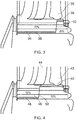
- Figure 4 shows an alternative embodiment to that of Figure 3 .
- the blade root is provided with a duct 46 defined by a wall 48.
- the wall has a terminal end 50 at approximately 50% along the bucket groove axis, adjacent a downstream wall of a second passage 44.
- the cross section of the duct remains substantially continuous along its walled length.
- a passage inlet is provided at a terminal end 49 of the third passage 45. This inlet is substantially smaller in cross section than the duct 46 so as to introduce a pressure drop into duct 45 and control the volume of coolant air consumed.
- Figure 5 illustrates the pressure of coolant flowing through different regions of the root of a blade having a configuration substantially similar to that of Figure 4 .
- the passages are not shown here, though it is to be understood that the pressure gradient represented is indicative of one in an arrangement with three passages as described in relation to Figures 2 to 4 .
- coolant arrives in a passage 55 between the disc and a cover plate and is delivered to duct 52 which is defined by wall 53 which has a terminal end 54 positioned at approximately 50% of the axial length of the bucket groove.
- FIG 6 shows, in perspective view, the external appearance of a blade root 61 of a blade in accordance with the invention.
- an upstream face 60 of the root has a substantially fir tree shape. This is designed to be received in a fir tree shaped recess 72 of a disc 77 as shown in Figure 7 .
- a terminal portion of the blade root 61 which sits in a bucket groove 73 of a disc 77 is provided with an inlet 62 in the upstream face 60 which, with the wall 63 defines a duct.
- the wall has a terminal end 64.
- a restrictor inlet 65 is provided at an entrance to a passage (for example the third passage of Figure 4 ) from the bucket groove space which is downstream of the terminal end 64 of the wall 63.
- the blade can be manufactured with a wall extending across the terminal end of the second passage and the restrictor inlet subsequently provided by cutting a hole into this wall section. An optimum size of the inlet can thus be selected once the operating parameters in which the blade will be used are known.
- Figure 7 shows a blade having the configuration as shown in Figure 6 , in situ in a disc 77.
- This Figure shows a view looking towards a downstream face 71 of the blade root.
- the root sits in a fir tree recess 72.
- Small spaces 75 are provided between the root and disc to allow for differential expansion of components at high operating temperatures.
- a terminal portion of the root sits in the bucket groove 73.
- the terminal end of a duct wall 74 can be seen partway along the axial extent of the bucket groove 73.
- Projections 76 extend partly into the groove space to assist in holding the root in place. Such projections may be configured to suit other purposes, such as connecting with circumferentially adjacent blade roots in an assembled turbine rotor stage.
Landscapes
- Engineering & Computer Science (AREA)
- Mechanical Engineering (AREA)
- General Engineering & Computer Science (AREA)
- Turbine Rotor Nozzle Sealing (AREA)
Claims (17)
- Turbinenschaufel mit einem Körper, der ein Labyrinth innerer Kanäle umschließt, die einen Strömungsweg für ein Kühlmittel definieren, das durch einen Einlass aufgenommen wird, der in einem Endabschnitt der Schaufelwurzel ausgebildet wird, wobei das Labyrinth umfasst;
den Einlass (7), der auf einer axial stromaufwärts gelegenen Seite des Endabschnitts angeordnet wird, der zu einem Kanal (36; 46) führt, der durch eine Wand (38; 48) definiert wird;
im Einsatz einen Zwischenraum (10), der durch eine Außenfläche der Kanalwand (48) und eine Bechernut einer Scheibe (2) begrenzt wird, in der die Schaufel geführt wird;
eine erste Durchführung, die den Kanal (36; 46) bei einer ersten Durchführungsschnittstelle schneidet und sich durch den Schaufelkörper in Richtung zu einer Kuppe der Schaufel erstreckt, wobei ein proximales Ende der ersten Durchführung angeordnet wird, im Einsatz eintretenden Kühlmittelfluss einzufangen; und
eine zweite Durchführung (35; 44), die den Kanal (36; 46) bei einer zweiten Durchführungsschnittstelle an einer Stelle stromabwärts gelegen der ersten Durchführungsschnittstelle schneidet;
dadurch gekennzeichnet, dass (i) der Zwischenraum bei der axial stromaufwärts gelegenen Seite eine Querschnittsfläche aufweist, die kleiner als die des Einlasses ist und einen auf den Einlass (7) gerichteten Leckweg für Luft definiert, (ii) der Schnittpunkt der Durchführungen mit dem Kanal eine Abfolge verringerter Querschnittsflächen in dem Strömungsweg in einer stromaufwärts bis stromabwärts gelegenen Richtung innerhalb des Kanals bildet, wodurch Druckverluste in die erste und zweite (35; 44) Durchführung eingeführt werden, um die Menge an verbrauchtem Kühlmittel zu steuern, und (iii) die Wand (38; 48) an einer axialen Position zwischen dem Einlass (7) und dem Schnittpunkt der zweiten Durchführung (35; 44) endet, wodurch die Querschnittsfläche des Strömungswegs bei dem Kanal bezogen auf eine angrenzende Querschnittsfläche des Zwischenraums erhöht wird, um den Kühlmitteldruck in dem Kanal (46) mit dem Kühlmitteldruck in dem Leckweg auszugleichen, wodurch sich ein Kühlmittelmassenstrom verringert, der in den Leckweg eintritt. - Turbinenschaufel nach Anspruch 1, wobei ein zweiter Durchführungseinlass zu der zweiten Durchführung (44) an der zweiten Durchführungsschnittstelle bereitgestellt wird, wobei der zweite Durchführungseinlass einen Querschnitt aufweist, der kleiner als der der zweiten Durchführungsschnittstelle ist.
- Turbinenschaufel nach Anspruch 1 oder Anspruch 2, wobei die erste Durchführung eine Vorderkantendurchführung ist.
- Turbinenschaufel nach einem der Ansprüche 1 bis 3, wobei die zweite Durchführung (35) eine Hinterkantendurchführung ist.
- Turbinenschaufel nach einem der Ansprüche 1 bis 3, wobei sich eine dritte Durchführung mit der zweiten Durchführung verbindet, um zwei Einlasswege zu einer Mehrfachdurchführung auszubilden, die sich durch einen Mittelabschnitt zu einem Hinterkantenabschnitt des Schaufelkörpers erstrecken.
- Turbinenschaufel nach einem der Ansprüche 1 bis 5, wobei die Wand (48) an einer stromaufwärts gelegenen Seite der zweiten Durchführungsschnittstelle endet.
- Turbinenschaufel nach einem der Ansprüche 1 bis 5, wobei die Wand (38; 48) entlang der zweiten Durchführungsschnittstelle endet.
- Turbinenschaufel nach einem vorhergehenden Anspruch, wobei sich die Wand (38; 48) axial zu einer Position erstreckt, die 50 % bis 85 % der axialen Länge der Bechernut beträgt.
- Turbinenschaufel nach Anspruch 6, wobei sich die Wand (38; 48) zu einer Position erstreckt, die 40 % bis 60 % der axialen Länge der Bechernut beträgt.
- Turbinenschaufel nach Anspruch 7, wobei sich die Wand (38; 48) zu einer Position erstreckt, die 70 % bis 90 % der axialen Länge der Bechernut beträgt.
- Turbinenschaufel nach einem vorhergehenden Anspruch, wobei der Kanal und Einlass (7) mit der Schaufel in einem einzigen Gießverfahren ganzheitlich ausgebildet werden.
- Turbinenschaufel nach einem der Ansprüche 1 bis 10, wobei die Kanalwand (38; 48) durch zwei oder mehrere Komponenten definiert wird, die anschließend verbunden oder miteinander befestigt werden.
- Turbinenschaufel nach Anspruch 12, wobei die Kanalwand durch Verwenden eines Additivschicht-Fertigungsverfahrens gefertigt wird und anschließend mit einem gegossenen Schaufelabschnitt reibverschweißt wird, der den Kanalwandrest definiert.
- Turbinenschaufel nach Anspruch 12, wobei der Kanal und Einlass ganzheitlich mit einer Verriegelungsplatte bereitgestellt werden, die an der Schaufel und/oder einer Scheibe mit einer Bechernut befestigt wird, die im Einsatz die Schaufel trägt.
- Turbinenschaufel nach Anspruch 12, wobei der Kanal (38; 48) und Einlass (7) in der Form eines Einsatzes bereitgestellt werden, der in einer Baugruppe der Schaufel und einer Scheibe mit einer Bechernut angeordnet wird, die im Einsatz die Schaufel trägt, nachdem die Schaufel in der Bechernut aufgenommen wurde.
- Turbinenschaufel nach Anspruch 12, wobei der Kanal (38; 48) und Einlass (7) ganzheitlich mit einer Abdichtungsplatte bereitgestellt werden, die an der Scheibe und/oder einer Scheibe mit einer Bechernut befestigt wird, die im Einsatz die Schaufel trägt.
- Gasturbinenmotor, der eine oder mehrere Scheiben mit Bechernuten umfasst, in denen sich die Turbinenschaufel mit der Konfiguration nach einem vorhergehenden Anspruch befindet.
Applications Claiming Priority (2)
| Application Number | Priority Date | Filing Date | Title |
|---|---|---|---|
| GBGB1516657.2A GB201516657D0 (en) | 2015-09-21 | 2015-09-21 | Seal-plate anti-rotation in a stage of a gas turbine engine |
| GBGB1519026.7A GB201519026D0 (en) | 2015-09-21 | 2015-10-28 | Thermal shielding in a gas turbine |
Publications (2)
| Publication Number | Publication Date |
|---|---|
| EP3144475A1 EP3144475A1 (de) | 2017-03-22 |
| EP3144475B1 true EP3144475B1 (de) | 2019-12-04 |
Family
ID=54544531
Family Applications (2)
| Application Number | Title | Priority Date | Filing Date |
|---|---|---|---|
| EP16187635.4A Active EP3144475B1 (de) | 2015-09-21 | 2016-09-07 | Thermalabschirmung in einer gasturbine |
| EP16187636.2A Active EP3144476B1 (de) | 2015-09-21 | 2016-09-07 | Verdrehschutz einer dichtplatte in einer stufe einer gasturbine |
Family Applications After (1)
| Application Number | Title | Priority Date | Filing Date |
|---|---|---|---|
| EP16187636.2A Active EP3144476B1 (de) | 2015-09-21 | 2016-09-07 | Verdrehschutz einer dichtplatte in einer stufe einer gasturbine |
Country Status (3)
| Country | Link |
|---|---|
| US (2) | US10443402B2 (de) |
| EP (2) | EP3144475B1 (de) |
| GB (2) | GB201516657D0 (de) |
Families Citing this family (5)
| Publication number | Priority date | Publication date | Assignee | Title |
|---|---|---|---|---|
| GB2572782B (en) * | 2018-04-10 | 2023-05-24 | Safran Electrical & Power | A Cooling Arrangement for a Generator |
| FR3085420B1 (fr) | 2018-09-04 | 2020-11-13 | Safran Aircraft Engines | Disque de rotor avec arret axial des aubes, ensemble d'un disque et d'un anneau et turbomachine |
| FR3092865B1 (fr) * | 2019-02-19 | 2021-01-29 | Safran Aircraft Engines | Disque de rotor avec arret axial des aubes, ensemble d’un disque et d’un anneau et turbomachine |
| US11066936B1 (en) * | 2020-05-07 | 2021-07-20 | Rolls-Royce Corporation | Turbine bladed disc brazed sealing plate with flow metering and axial retention features |
| GB202111579D0 (en) | 2021-08-12 | 2021-09-29 | Rolls Royce Plc | Blade intake |
Family Cites Families (18)
| Publication number | Priority date | Publication date | Assignee | Title |
|---|---|---|---|---|
| US3395891A (en) * | 1967-09-21 | 1968-08-06 | Gen Electric | Lock for turbomachinery blades |
| US3853425A (en) | 1973-09-07 | 1974-12-10 | Westinghouse Electric Corp | Turbine rotor blade cooling and sealing system |
| IT1025260B (it) * | 1973-11-16 | 1978-08-10 | Mtu Muenchen Gmbh | Turbina a raffreddamento interno della corona e con posizioni prescritte di rottura |
| US4279572A (en) | 1979-07-09 | 1981-07-21 | United Technologies Corporation | Sideplates for rotor disk and rotor blades |
| GB2194000A (en) | 1986-08-13 | 1988-02-24 | Rolls Royce Plc | Turbine rotor assembly with seal plates |
| GB2319308B (en) * | 1996-11-12 | 2001-02-28 | Rolls Royce Plc | Gas turbine engine turbine system |
| FR2823794B1 (fr) | 2001-04-19 | 2003-07-11 | Snecma Moteurs | Aube rapportee et refroidie pour turbine |
| US7442007B2 (en) | 2005-06-02 | 2008-10-28 | Pratt & Whitney Canada Corp. | Angled blade firtree retaining system |
| US7244101B2 (en) | 2005-10-04 | 2007-07-17 | General Electric Company | Dust resistant platform blade |
| DE102006054154B4 (de) | 2006-11-16 | 2014-03-13 | Man Diesel & Turbo Se | Abgasturbolader |
| GB2452515B (en) | 2007-09-06 | 2009-08-05 | Siemens Ag | Seal coating between rotor blade and rotor disk slot in gas turbine engine |
| US8113784B2 (en) * | 2009-03-20 | 2012-02-14 | Hamilton Sundstrand Corporation | Coolable airfoil attachment section |
| US8602737B2 (en) | 2010-06-25 | 2013-12-10 | General Electric Company | Sealing device |
| RU2543100C2 (ru) * | 2010-11-29 | 2015-02-27 | Альстом Текнолоджи Лтд | Рабочая лопатка для газовой турбины, способ изготовления указанной лопатки и газовая турбина с такой лопаткой |
| DE102011121634B4 (de) * | 2010-12-27 | 2019-08-14 | Ansaldo Energia Ip Uk Limited | Turbinenschaufel |
| GB201417038D0 (en) | 2014-09-26 | 2014-11-12 | Rolls Royce Plc | A bladed rotor arrangement |
| GB201506728D0 (en) * | 2015-04-21 | 2015-06-03 | Rolls Royce Plc | Thermal shielding in a gas turbine |
| GB201512810D0 (en) * | 2015-07-21 | 2015-09-02 | Rolls Royce Plc | Thermal shielding in a gas turbine |
-
2015
- 2015-09-21 GB GBGB1516657.2A patent/GB201516657D0/en not_active Ceased
- 2015-10-28 GB GBGB1519026.7A patent/GB201519026D0/en not_active Ceased
-
2016
- 2016-09-07 EP EP16187635.4A patent/EP3144475B1/de active Active
- 2016-09-07 EP EP16187636.2A patent/EP3144476B1/de active Active
- 2016-09-07 US US15/258,701 patent/US10443402B2/en active Active
- 2016-09-07 US US15/258,721 patent/US10352175B2/en active Active
Non-Patent Citations (1)
| Title |
|---|
| None * |
Also Published As
| Publication number | Publication date |
|---|---|
| GB201516657D0 (en) | 2015-11-04 |
| EP3144476A1 (de) | 2017-03-22 |
| GB201519026D0 (en) | 2015-12-09 |
| EP3144476B1 (de) | 2019-04-24 |
| US20180252109A9 (en) | 2018-09-06 |
| US20170198589A1 (en) | 2017-07-13 |
| US20170191370A1 (en) | 2017-07-06 |
| US10352175B2 (en) | 2019-07-16 |
| US10443402B2 (en) | 2019-10-15 |
| EP3144475A1 (de) | 2017-03-22 |
Similar Documents
| Publication | Publication Date | Title |
|---|---|---|
| US9476305B2 (en) | Impingement-cooled turbine rotor | |
| US10301964B2 (en) | Baffle with flow augmentation feature | |
| US7607891B2 (en) | Turbine component with tip flagged pedestal cooling | |
| US9115586B2 (en) | Axially-split radial turbine | |
| EP3144475B1 (de) | Thermalabschirmung in einer gasturbine | |
| CN110325711A (zh) | 涡轮发动机的花键 | |
| US8297925B2 (en) | Aerofoil configuration | |
| US10364678B2 (en) | Thermal shielding in a gas turbine | |
| CN102454427A (zh) | 用于冷却涡轮转子叶片的平台区域的设备、系统和方法 | |
| US10677064B2 (en) | Thermal shielding in a gas turbine | |
| US20130028735A1 (en) | Blade cooling and sealing system | |
| US20220220854A1 (en) | Turbine engine with an airfoil having a set of dimples | |
| US20170130588A1 (en) | Shrouded turbine blade | |
| US10794194B2 (en) | Staggered core printout | |
| US9677475B2 (en) | Gas turbine engine with high speed and temperature spool cooling system | |
| EP3647544A1 (de) | Gegühltes gasturbinen leitschaufelprofil | |
| US8419366B2 (en) | Blade | |
| EP3556996B1 (de) | Schaufel mit einlassöffnung auf der vorderen stirnseite des fusses | |
| US10253636B2 (en) | Flow exchange baffle insert for a gas turbine engine component | |
| US10508548B2 (en) | Turbine engine with a platform cooling circuit | |
| EP3203026B1 (de) | Gasturbinenschaufel mit sockelanordnung | |
| US20220090504A1 (en) | Rotor blade for a gas turbine engine having a metallic structural member and a composite fairing |
Legal Events
| Date | Code | Title | Description |
|---|---|---|---|
| PUAI | Public reference made under article 153(3) epc to a published international application that has entered the european phase |
Free format text: ORIGINAL CODE: 0009012 |
|
| STAA | Information on the status of an ep patent application or granted ep patent |
Free format text: STATUS: THE APPLICATION HAS BEEN PUBLISHED |
|
| AK | Designated contracting states |
Kind code of ref document: A1 Designated state(s): AL AT BE BG CH CY CZ DE DK EE ES FI FR GB GR HR HU IE IS IT LI LT LU LV MC MK MT NL NO PL PT RO RS SE SI SK SM TR |
|
| AX | Request for extension of the european patent |
Extension state: BA ME |
|
| STAA | Information on the status of an ep patent application or granted ep patent |
Free format text: STATUS: REQUEST FOR EXAMINATION WAS MADE |
|
| 17P | Request for examination filed |
Effective date: 20170919 |
|
| RBV | Designated contracting states (corrected) |
Designated state(s): AL AT BE BG CH CY CZ DE DK EE ES FI FR GB GR HR HU IE IS IT LI LT LU LV MC MK MT NL NO PL PT RO RS SE SI SK SM TR |
|
| STAA | Information on the status of an ep patent application or granted ep patent |
Free format text: STATUS: EXAMINATION IS IN PROGRESS |
|
| 17Q | First examination report despatched |
Effective date: 20180306 |
|
| GRAP | Despatch of communication of intention to grant a patent |
Free format text: ORIGINAL CODE: EPIDOSNIGR1 |
|
| STAA | Information on the status of an ep patent application or granted ep patent |
Free format text: STATUS: GRANT OF PATENT IS INTENDED |
|
| GRAS | Grant fee paid |
Free format text: ORIGINAL CODE: EPIDOSNIGR3 |
|
| GRAA | (expected) grant |
Free format text: ORIGINAL CODE: 0009210 |
|
| STAA | Information on the status of an ep patent application or granted ep patent |
Free format text: STATUS: THE PATENT HAS BEEN GRANTED |
|
| INTG | Intention to grant announced |
Effective date: 20191016 |
|
| RAP1 | Party data changed (applicant data changed or rights of an application transferred) |
Owner name: ROLLS-ROYCE PLC |
|
| AK | Designated contracting states |
Kind code of ref document: B1 Designated state(s): AL AT BE BG CH CY CZ DE DK EE ES FI FR GB GR HR HU IE IS IT LI LT LU LV MC MK MT NL NO PL PT RO RS SE SI SK SM TR |
|
| REG | Reference to a national code |
Ref country code: GB Ref legal event code: FG4D |
|
| REG | Reference to a national code |
Ref country code: CH Ref legal event code: EP |
|
| REG | Reference to a national code |
Ref country code: AT Ref legal event code: REF Ref document number: 1209650 Country of ref document: AT Kind code of ref document: T Effective date: 20191215 |
|
| REG | Reference to a national code |
Ref country code: DE Ref legal event code: R096 Ref document number: 602016025404 Country of ref document: DE |
|
| REG | Reference to a national code |
Ref country code: IE Ref legal event code: FG4D |
|
| RAP2 | Party data changed (patent owner data changed or rights of a patent transferred) |
Owner name: ROLLS-ROYCE PLC |
|
| REG | Reference to a national code |
Ref country code: NL Ref legal event code: MP Effective date: 20191204 |
|
| REG | Reference to a national code |
Ref country code: LT Ref legal event code: MG4D |
|
| PG25 | Lapsed in a contracting state [announced via postgrant information from national office to epo] |
Ref country code: NO Free format text: LAPSE BECAUSE OF FAILURE TO SUBMIT A TRANSLATION OF THE DESCRIPTION OR TO PAY THE FEE WITHIN THE PRESCRIBED TIME-LIMIT Effective date: 20200304 Ref country code: GR Free format text: LAPSE BECAUSE OF FAILURE TO SUBMIT A TRANSLATION OF THE DESCRIPTION OR TO PAY THE FEE WITHIN THE PRESCRIBED TIME-LIMIT Effective date: 20200305 Ref country code: LT Free format text: LAPSE BECAUSE OF FAILURE TO SUBMIT A TRANSLATION OF THE DESCRIPTION OR TO PAY THE FEE WITHIN THE PRESCRIBED TIME-LIMIT Effective date: 20191204 Ref country code: LV Free format text: LAPSE BECAUSE OF FAILURE TO SUBMIT A TRANSLATION OF THE DESCRIPTION OR TO PAY THE FEE WITHIN THE PRESCRIBED TIME-LIMIT Effective date: 20191204 Ref country code: BG Free format text: LAPSE BECAUSE OF FAILURE TO SUBMIT A TRANSLATION OF THE DESCRIPTION OR TO PAY THE FEE WITHIN THE PRESCRIBED TIME-LIMIT Effective date: 20200304 Ref country code: SE Free format text: LAPSE BECAUSE OF FAILURE TO SUBMIT A TRANSLATION OF THE DESCRIPTION OR TO PAY THE FEE WITHIN THE PRESCRIBED TIME-LIMIT Effective date: 20191204 Ref country code: FI Free format text: LAPSE BECAUSE OF FAILURE TO SUBMIT A TRANSLATION OF THE DESCRIPTION OR TO PAY THE FEE WITHIN THE PRESCRIBED TIME-LIMIT Effective date: 20191204 |
|
| PG25 | Lapsed in a contracting state [announced via postgrant information from national office to epo] |
Ref country code: RS Free format text: LAPSE BECAUSE OF FAILURE TO SUBMIT A TRANSLATION OF THE DESCRIPTION OR TO PAY THE FEE WITHIN THE PRESCRIBED TIME-LIMIT Effective date: 20191204 Ref country code: HR Free format text: LAPSE BECAUSE OF FAILURE TO SUBMIT A TRANSLATION OF THE DESCRIPTION OR TO PAY THE FEE WITHIN THE PRESCRIBED TIME-LIMIT Effective date: 20191204 |
|
| PG25 | Lapsed in a contracting state [announced via postgrant information from national office to epo] |
Ref country code: AL Free format text: LAPSE BECAUSE OF FAILURE TO SUBMIT A TRANSLATION OF THE DESCRIPTION OR TO PAY THE FEE WITHIN THE PRESCRIBED TIME-LIMIT Effective date: 20191204 |
|
| PG25 | Lapsed in a contracting state [announced via postgrant information from national office to epo] |
Ref country code: EE Free format text: LAPSE BECAUSE OF FAILURE TO SUBMIT A TRANSLATION OF THE DESCRIPTION OR TO PAY THE FEE WITHIN THE PRESCRIBED TIME-LIMIT Effective date: 20191204 Ref country code: PT Free format text: LAPSE BECAUSE OF FAILURE TO SUBMIT A TRANSLATION OF THE DESCRIPTION OR TO PAY THE FEE WITHIN THE PRESCRIBED TIME-LIMIT Effective date: 20200429 Ref country code: RO Free format text: LAPSE BECAUSE OF FAILURE TO SUBMIT A TRANSLATION OF THE DESCRIPTION OR TO PAY THE FEE WITHIN THE PRESCRIBED TIME-LIMIT Effective date: 20191204 Ref country code: NL Free format text: LAPSE BECAUSE OF FAILURE TO SUBMIT A TRANSLATION OF THE DESCRIPTION OR TO PAY THE FEE WITHIN THE PRESCRIBED TIME-LIMIT Effective date: 20191204 Ref country code: CZ Free format text: LAPSE BECAUSE OF FAILURE TO SUBMIT A TRANSLATION OF THE DESCRIPTION OR TO PAY THE FEE WITHIN THE PRESCRIBED TIME-LIMIT Effective date: 20191204 Ref country code: ES Free format text: LAPSE BECAUSE OF FAILURE TO SUBMIT A TRANSLATION OF THE DESCRIPTION OR TO PAY THE FEE WITHIN THE PRESCRIBED TIME-LIMIT Effective date: 20191204 |
|
| PG25 | Lapsed in a contracting state [announced via postgrant information from national office to epo] |
Ref country code: SM Free format text: LAPSE BECAUSE OF FAILURE TO SUBMIT A TRANSLATION OF THE DESCRIPTION OR TO PAY THE FEE WITHIN THE PRESCRIBED TIME-LIMIT Effective date: 20191204 Ref country code: IS Free format text: LAPSE BECAUSE OF FAILURE TO SUBMIT A TRANSLATION OF THE DESCRIPTION OR TO PAY THE FEE WITHIN THE PRESCRIBED TIME-LIMIT Effective date: 20200404 Ref country code: SK Free format text: LAPSE BECAUSE OF FAILURE TO SUBMIT A TRANSLATION OF THE DESCRIPTION OR TO PAY THE FEE WITHIN THE PRESCRIBED TIME-LIMIT Effective date: 20191204 |
|
| REG | Reference to a national code |
Ref country code: DE Ref legal event code: R097 Ref document number: 602016025404 Country of ref document: DE |
|
| REG | Reference to a national code |
Ref country code: AT Ref legal event code: MK05 Ref document number: 1209650 Country of ref document: AT Kind code of ref document: T Effective date: 20191204 |
|
| PLBE | No opposition filed within time limit |
Free format text: ORIGINAL CODE: 0009261 |
|
| STAA | Information on the status of an ep patent application or granted ep patent |
Free format text: STATUS: NO OPPOSITION FILED WITHIN TIME LIMIT |
|
| PG25 | Lapsed in a contracting state [announced via postgrant information from national office to epo] |
Ref country code: DK Free format text: LAPSE BECAUSE OF FAILURE TO SUBMIT A TRANSLATION OF THE DESCRIPTION OR TO PAY THE FEE WITHIN THE PRESCRIBED TIME-LIMIT Effective date: 20191204 |
|
| 26N | No opposition filed |
Effective date: 20200907 |
|
| PG25 | Lapsed in a contracting state [announced via postgrant information from national office to epo] |
Ref country code: AT Free format text: LAPSE BECAUSE OF FAILURE TO SUBMIT A TRANSLATION OF THE DESCRIPTION OR TO PAY THE FEE WITHIN THE PRESCRIBED TIME-LIMIT Effective date: 20191204 Ref country code: PL Free format text: LAPSE BECAUSE OF FAILURE TO SUBMIT A TRANSLATION OF THE DESCRIPTION OR TO PAY THE FEE WITHIN THE PRESCRIBED TIME-LIMIT Effective date: 20191204 Ref country code: SI Free format text: LAPSE BECAUSE OF FAILURE TO SUBMIT A TRANSLATION OF THE DESCRIPTION OR TO PAY THE FEE WITHIN THE PRESCRIBED TIME-LIMIT Effective date: 20191204 |
|
| PG25 | Lapsed in a contracting state [announced via postgrant information from national office to epo] |
Ref country code: IT Free format text: LAPSE BECAUSE OF FAILURE TO SUBMIT A TRANSLATION OF THE DESCRIPTION OR TO PAY THE FEE WITHIN THE PRESCRIBED TIME-LIMIT Effective date: 20191204 |
|
| PGFP | Annual fee paid to national office [announced via postgrant information from national office to epo] |
Ref country code: DE Payment date: 20201127 Year of fee payment: 5 |
|
| PG25 | Lapsed in a contracting state [announced via postgrant information from national office to epo] |
Ref country code: MC Free format text: LAPSE BECAUSE OF FAILURE TO SUBMIT A TRANSLATION OF THE DESCRIPTION OR TO PAY THE FEE WITHIN THE PRESCRIBED TIME-LIMIT Effective date: 20191204 |
|
| REG | Reference to a national code |
Ref country code: CH Ref legal event code: PL |
|
| REG | Reference to a national code |
Ref country code: BE Ref legal event code: MM Effective date: 20200930 |
|
| PG25 | Lapsed in a contracting state [announced via postgrant information from national office to epo] |
Ref country code: LU Free format text: LAPSE BECAUSE OF NON-PAYMENT OF DUE FEES Effective date: 20200907 |
|
| PG25 | Lapsed in a contracting state [announced via postgrant information from national office to epo] |
Ref country code: BE Free format text: LAPSE BECAUSE OF NON-PAYMENT OF DUE FEES Effective date: 20200930 Ref country code: CH Free format text: LAPSE BECAUSE OF NON-PAYMENT OF DUE FEES Effective date: 20200930 Ref country code: LI Free format text: LAPSE BECAUSE OF NON-PAYMENT OF DUE FEES Effective date: 20200930 Ref country code: IE Free format text: LAPSE BECAUSE OF NON-PAYMENT OF DUE FEES Effective date: 20200907 |
|
| REG | Reference to a national code |
Ref country code: DE Ref legal event code: R119 Ref document number: 602016025404 Country of ref document: DE |
|
| PG25 | Lapsed in a contracting state [announced via postgrant information from national office to epo] |
Ref country code: TR Free format text: LAPSE BECAUSE OF FAILURE TO SUBMIT A TRANSLATION OF THE DESCRIPTION OR TO PAY THE FEE WITHIN THE PRESCRIBED TIME-LIMIT Effective date: 20191204 Ref country code: MT Free format text: LAPSE BECAUSE OF FAILURE TO SUBMIT A TRANSLATION OF THE DESCRIPTION OR TO PAY THE FEE WITHIN THE PRESCRIBED TIME-LIMIT Effective date: 20191204 Ref country code: CY Free format text: LAPSE BECAUSE OF FAILURE TO SUBMIT A TRANSLATION OF THE DESCRIPTION OR TO PAY THE FEE WITHIN THE PRESCRIBED TIME-LIMIT Effective date: 20191204 |
|
| PG25 | Lapsed in a contracting state [announced via postgrant information from national office to epo] |
Ref country code: MK Free format text: LAPSE BECAUSE OF FAILURE TO SUBMIT A TRANSLATION OF THE DESCRIPTION OR TO PAY THE FEE WITHIN THE PRESCRIBED TIME-LIMIT Effective date: 20191204 |
|
| PG25 | Lapsed in a contracting state [announced via postgrant information from national office to epo] |
Ref country code: DE Free format text: LAPSE BECAUSE OF NON-PAYMENT OF DUE FEES Effective date: 20220401 |
|
| P01 | Opt-out of the competence of the unified patent court (upc) registered |
Effective date: 20230528 |
|
| PGFP | Annual fee paid to national office [announced via postgrant information from national office to epo] |
Ref country code: GB Payment date: 20250923 Year of fee payment: 10 |
|
| PGFP | Annual fee paid to national office [announced via postgrant information from national office to epo] |
Ref country code: FR Payment date: 20250925 Year of fee payment: 10 |