EP3144494A1 - Systeme de recuperation d'energie des gaz d'echappement et procede de recuperation d'energie des gaz d'echappement - Google Patents
Systeme de recuperation d'energie des gaz d'echappement et procede de recuperation d'energie des gaz d'echappement Download PDFInfo
- Publication number
- EP3144494A1 EP3144494A1 EP15186105.1A EP15186105A EP3144494A1 EP 3144494 A1 EP3144494 A1 EP 3144494A1 EP 15186105 A EP15186105 A EP 15186105A EP 3144494 A1 EP3144494 A1 EP 3144494A1
- Authority
- EP
- European Patent Office
- Prior art keywords
- exhaust gas
- exhaust
- sealing strips
- energy recovery
- engine
- Prior art date
- Legal status (The legal status is an assumption and is not a legal conclusion. Google has not performed a legal analysis and makes no representation as to the accuracy of the status listed.)
- Granted
Links
Images

Classifications
-
- F—MECHANICAL ENGINEERING; LIGHTING; HEATING; WEAPONS; BLASTING
- F01—MACHINES OR ENGINES IN GENERAL; ENGINE PLANTS IN GENERAL; STEAM ENGINES
- F01N—GAS-FLOW SILENCERS OR EXHAUST APPARATUS FOR MACHINES OR ENGINES IN GENERAL; GAS-FLOW SILENCERS OR EXHAUST APPARATUS FOR INTERNAL-COMBUSTION ENGINES
- F01N5/00—Exhaust or silencing apparatus combined or associated with devices profiting by exhaust energy
- F01N5/04—Exhaust or silencing apparatus combined or associated with devices profiting by exhaust energy the devices using kinetic energy
-
- F—MECHANICAL ENGINEERING; LIGHTING; HEATING; WEAPONS; BLASTING
- F01—MACHINES OR ENGINES IN GENERAL; ENGINE PLANTS IN GENERAL; STEAM ENGINES
- F01C—ROTARY-PISTON OR OSCILLATING-PISTON MACHINES OR ENGINES
- F01C1/00—Rotary-piston machines or engines
- F01C1/08—Rotary-piston machines or engines of intermeshing engagement type, i.e. with engagement of co- operating members similar to that of toothed gearing
- F01C1/12—Rotary-piston machines or engines of intermeshing engagement type, i.e. with engagement of co- operating members similar to that of toothed gearing of other than internal-axis type
- F01C1/123—Rotary-piston machines or engines of intermeshing engagement type, i.e. with engagement of co- operating members similar to that of toothed gearing of other than internal-axis type with tooth-like elements, extending generally radially from the rotor body cooperating with recesses in the other rotor, e.g. one tooth
-
- F—MECHANICAL ENGINEERING; LIGHTING; HEATING; WEAPONS; BLASTING
- F01—MACHINES OR ENGINES IN GENERAL; ENGINE PLANTS IN GENERAL; STEAM ENGINES
- F01C—ROTARY-PISTON OR OSCILLATING-PISTON MACHINES OR ENGINES
- F01C11/00—Combinations of two or more machines or engines, each being of rotary-piston or oscillating-piston type
- F01C11/006—Combinations of two or more machines or engines, each being of rotary-piston or oscillating-piston type of dissimilar working principle
- F01C11/008—Combinations of two or more machines or engines, each being of rotary-piston or oscillating-piston type of dissimilar working principle and of complementary function, e.g. internal combustion engine with supercharger
-
- F—MECHANICAL ENGINEERING; LIGHTING; HEATING; WEAPONS; BLASTING
- F01—MACHINES OR ENGINES IN GENERAL; ENGINE PLANTS IN GENERAL; STEAM ENGINES
- F01C—ROTARY-PISTON OR OSCILLATING-PISTON MACHINES OR ENGINES
- F01C19/00—Sealing arrangements in rotary-piston machines or engines
- F01C19/02—Radially-movable sealings for working fluids
- F01C19/025—Radial sealing elements specially adapted for intermeshing engagement type machines or engines, e.g. gear machines or engines
-
- F—MECHANICAL ENGINEERING; LIGHTING; HEATING; WEAPONS; BLASTING
- F01—MACHINES OR ENGINES IN GENERAL; ENGINE PLANTS IN GENERAL; STEAM ENGINES
- F01N—GAS-FLOW SILENCERS OR EXHAUST APPARATUS FOR MACHINES OR ENGINES IN GENERAL; GAS-FLOW SILENCERS OR EXHAUST APPARATUS FOR INTERNAL-COMBUSTION ENGINES
- F01N5/00—Exhaust or silencing apparatus combined or associated with devices profiting by exhaust energy
-
- F—MECHANICAL ENGINEERING; LIGHTING; HEATING; WEAPONS; BLASTING
- F01—MACHINES OR ENGINES IN GENERAL; ENGINE PLANTS IN GENERAL; STEAM ENGINES
- F01N—GAS-FLOW SILENCERS OR EXHAUST APPARATUS FOR MACHINES OR ENGINES IN GENERAL; GAS-FLOW SILENCERS OR EXHAUST APPARATUS FOR INTERNAL-COMBUSTION ENGINES
- F01N5/00—Exhaust or silencing apparatus combined or associated with devices profiting by exhaust energy
- F01N5/02—Exhaust or silencing apparatus combined or associated with devices profiting by exhaust energy the devices using heat
-
- F—MECHANICAL ENGINEERING; LIGHTING; HEATING; WEAPONS; BLASTING
- F02—COMBUSTION ENGINES; HOT-GAS OR COMBUSTION-PRODUCT ENGINE PLANTS
- F02B—INTERNAL-COMBUSTION PISTON ENGINES; COMBUSTION ENGINES IN GENERAL
- F02B41/00—Engines characterised by special means for improving conversion of heat or pressure energy into mechanical power
- F02B41/02—Engines with prolonged expansion
- F02B41/10—Engines with prolonged expansion in exhaust turbines
-
- F—MECHANICAL ENGINEERING; LIGHTING; HEATING; WEAPONS; BLASTING
- F02—COMBUSTION ENGINES; HOT-GAS OR COMBUSTION-PRODUCT ENGINE PLANTS
- F02G—HOT GAS OR COMBUSTION-PRODUCT POSITIVE-DISPLACEMENT ENGINE PLANTS; USE OF WASTE HEAT OF COMBUSTION ENGINES; NOT OTHERWISE PROVIDED FOR
- F02G5/00—Profiting from waste heat of combustion engines, not otherwise provided for
- F02G5/02—Profiting from waste heat of exhaust gases
- F02G5/04—Profiting from waste heat of exhaust gases in combination with other waste heat from combustion engines
-
- F—MECHANICAL ENGINEERING; LIGHTING; HEATING; WEAPONS; BLASTING
- F01—MACHINES OR ENGINES IN GENERAL; ENGINE PLANTS IN GENERAL; STEAM ENGINES
- F01C—ROTARY-PISTON OR OSCILLATING-PISTON MACHINES OR ENGINES
- F01C21/00—Component parts, details or accessories not provided for in groups F01C1/00 - F01C20/00
- F01C21/008—Driving elements, brakes, couplings, transmissions specially adapted for rotary or oscillating-piston machines or engines
-
- F—MECHANICAL ENGINEERING; LIGHTING; HEATING; WEAPONS; BLASTING
- F01—MACHINES OR ENGINES IN GENERAL; ENGINE PLANTS IN GENERAL; STEAM ENGINES
- F01N—GAS-FLOW SILENCERS OR EXHAUST APPARATUS FOR MACHINES OR ENGINES IN GENERAL; GAS-FLOW SILENCERS OR EXHAUST APPARATUS FOR INTERNAL-COMBUSTION ENGINES
- F01N3/00—Exhaust or silencing apparatus having means for purifying, rendering innocuous, or otherwise treating exhaust
-
- Y—GENERAL TAGGING OF NEW TECHNOLOGICAL DEVELOPMENTS; GENERAL TAGGING OF CROSS-SECTIONAL TECHNOLOGIES SPANNING OVER SEVERAL SECTIONS OF THE IPC; TECHNICAL SUBJECTS COVERED BY FORMER USPC CROSS-REFERENCE ART COLLECTIONS [XRACs] AND DIGESTS
- Y02—TECHNOLOGIES OR APPLICATIONS FOR MITIGATION OR ADAPTATION AGAINST CLIMATE CHANGE
- Y02T—CLIMATE CHANGE MITIGATION TECHNOLOGIES RELATED TO TRANSPORTATION
- Y02T10/00—Road transport of goods or passengers
- Y02T10/10—Internal combustion engine [ICE] based vehicles
- Y02T10/12—Improving ICE efficiencies
Definitions
- the present invention relates to an exhaust gas energy recovery system according to the preamble of claim 1 and to a method for exhaust gas energy recovery according to the preamble of claim 15.
- a generic exhaust gas energy recovery system comprises an exhaust pipe system for conducting exhaust gases of an internal combustion engine and a motor-generator device which can be driven via exhaust energy for generating electric current.
- Known exhaust gas energy recovery systems use thermal energy of the exhaust gas to generate electrical energy therefrom.
- the heat of the exhaust gas is transferred to a different working fluid.
- the working fluid is usually in a closed circuit and passes through the engine.
- a line system of the working fluid comprises further components, such as a pump, a condenser, possibly further heaters and a recuperator. The selection of these components depends on the cycle process performed. Especially Rankine cycles are used, which are also referred to as ORC or Organic Rankine Cycle.
- an object of the invention it may be considered to provide an exhaust gas energy recovery system and method for exhaust gas energy recovery which utilize exhaust energy as efficiently as possible.
- the exhaust pipe system includes a pipe (hereinafter also referred to as a first pipe arm) to the motor-generating device for passing exhaust gases into the motor-generator device, and the motor-generator device comprises a motor which is arranged so that it can be driven by a pressure of exhaust gas flowing through it.
- exhaust gases are conducted into the motor-generator device via a line of an exhaust pipe system.
- This comprises a motor which is driven by a pressure of exhaust gas flowing through it.
- the pressure of the exhaust gas is used to generate electric power. While so far only the heat of the exhaust gas has been used to generate electricity, the exhaust gas pressure can be additionally or alternatively used by the invention. Thus, kinetic energy of the exhaust gas, which previously remained unused, at least partially converted into electrical energy.
- exhaust gases are passed directly through the motor of the motor generator assembly. This is relevant in order to use as much of the energy as possible in print. Advantageous designs of the engine to allow the highest possible efficiency even at rather low pressure will be described in more detail below.
- the motor-generator device can generally be understood to mean a device which comprises a motor and is set up to convert kinetic energy into electrical energy.
- the components required for this purpose can locally form a unit or be present locally separated from each other and be operatively connected to each other.
- a generator may be present, by which means can generally be understood, with which the (rotation) movement provided by the motor can be converted into electrical energy.
- an internal combustion engine and an exhaust gas treatment system for purifying exhaust gases may also be considered.
- the exhaust pipe system may now be adapted to direct at least a portion of the exhaust gases of the internal combustion engine, first by the engine of the engine-generator assembly and then to the exhaust treatment system.
- the motor-generator device By locating the motor-generator device upstream of the exhaust-gas treatment system, the energy present in the pressure can be utilized before the pressure drops through the exhaust-gas treatment system. If a turbocharger is present, then the motor-generator device is preferably downstream of the turbocharger. As a result, in particular retrofitting of conventional systems is facilitated since the interacting components can remain unchanged up to the turbocharger.
- the exhaust conduit system may include a branch from which a first conduit arm passes over the engine toward the exhaust treatment system and a second conduit arm bypasses the engine and travels toward the exhaust treatment system.
- Control means may be present at the branch and arranged to adjust to what portions exhaust gas is split between the first and second conduit arms.
- Advantageously, can be adjusted by the control in particular a desired minimum pressure of the exhaust gas behind the engine become.
- a maximum amount of exhaust gases to the engine can be adjusted to meet limits of its suitable operating conditions.
- it is set via the said control, how much electrical energy is generated. For example, it may be provided to reduce the amount of exhaust gases to the engine when less electrical energy is needed and / or when an electrical energy store is fully charged.
- the control means preferably comprise a rotatable flap. Their rotational position specifies to what proportions exhaust gas is conducted into an inlet opening of the first conduit arm and into an inlet opening of the second conduit arm. In this way, control can be done reliably with simple means.
- the motor of the motor-generator device can be of any type. It should be noted, however, that many engines show sufficient efficiency only at relatively high pressure. In addition, many engines set narrow criteria for a medium flowing through, for example, in terms of its temperature or viscosity. For the highest possible efficiency, the medium conducted by the engine should be the exhaust gas itself. Hereinafter, preferred features of the engine will be described in order to use the exhaust gas pressure as efficiently as possible.
- the engine is preferably a rotary piston engine in which at least one rotary piston is rotatable by flowing exhaust gas and thus drives a shaft via which in turn the generator is driven.
- the rotary engine may have a housing which forms an interior. In the interior, at least one, preferably at least or exactly two rotary pistons are arranged. In addition, an inlet opening for the introduction of exhaust gases is provided in the interior. The inlet opening is connected to the exhaust pipe system, in particular to the first pipe arm.
- the rotary piston engine further comprises an exhaust gas outlet, which is located on the interior side at an opposite side of the inlet opening. Exhaust gases thus flow through the interior and thereby put the rotary piston or in rotation.
- Each rotary piston preferably has at least two sealing strips and at least two recesses on its outer circumference.
- the forms of the depressions and the Sealing strips are selected for, in particular sealing, engagement of the sealing strips of one of the rotary pistons in the recesses of the other rotary piston.
- the sealing strips are dimensioned in the radial direction for sealingly contacting a housing inner wall.
- the radial direction refers to the radius of the associated rotary piston, whereby the radial direction is transverse or perpendicular to the direction of rotation of the respective rotary piston.
- the exhaust gas coming from the inlet opening presses against (at least) some of the sealing strips, as a result of which these sealing strips are pressed against the inside wall of the housing.
- at least one (or exactly one) of the sealing strips of each rotary piston can be exposed to the incoming exhaust gas and thus be pressed by this against the inner wall of the housing.
- a seal of a rotary piston engine is effected via sealing strips, which are switched on or attached to the rotary piston.
- An exhaust gas pressure can act on the sealing strips and press them against the housing inner wall, whereby a particularly good seal is produced.
- the exhaust pressure leads to a certain deformation of the sealing strips, which is important for efficient sealing.
- the sealing exhaust gas pressure can already be achieved at a relatively low pressure. Also, the viscosity of the exhaust gas plays only a minor role. Therefore, the rotary engine can be used for different exhaust gas compositions and under very different pressures. As a further advantage, lubricants or oils may not be required in the rotary engine.
- a particularly good seal can be achieved if the sealing strips comprise a deformable or elastic material, so that they can be pressed / deformed sealingly against the housing inner wall by the exhaust gas.
- the material of the sealing strips is easier to deform or more elastic than a material surrounding the sealing strips of the rotary piston, in particular as the material from which the grooves described in more detail below for receiving the sealing strips are formed.
- the rotary pistons are dimensioned and arranged in the interior, that the exhaust gas can only pass from the inlet opening to the outlet opening, when the rotary pistons are rotated. In other words, cause the two rotary piston at standstill a seal so that no rotation can flow through the interior without rotation.
- a contact of the two rotary pistons is necessary. Through this contact little or no exhaust gas can pass between the two rotary pistons.
- a contact of the two rotary pistons to the housing inner wall is required for the seal. This contact is at least on an outwardly facing side of the respective rotary piston, which faces away from the contact area between the rotary piston.
- each rotary piston by means of its sealing strips provide a sealing contact with the adjacent housing inner wall over an angular range of at least 150 °, preferably at least 180 ° and more preferably more than 180 °.
- the sealing strips may extend in a longitudinal direction, which is substantially parallel to the axes of rotation of the two rotary pistons.
- an angle between the longitudinal direction and the axes of rotation may be less than 20 °, preferably less than 10 °.
- the two axes of rotation of the two rotary pistons can also be parallel to each other or at least at an angle which is at most 40 ° or preferably at most 20 °.
- the two rotary pistons can be formed identically. If asymmetrical sealing strips are used, as described later, then the rotary pistons can be identical except for a mirrored arrangement or shaping of the sealing strips.
- an object Under a rotary piston, an object can be understood, which is rotatably mounted and rotates with rotation, a shaft. The rotation of this shaft can then be used to, for example, set other objects in rotation and / or generate electrical energy via the generator of the motor-generator device.
- the sealing strips can be received in grooves, ie grooves or similar recesses, which are formed on the respective outer circumference of the rotary piston.
- the grooves in later described sprockets of the rotary piston may be formed.
- the sealing strips can be attached in principle any way. The sealing strips can thus be exchangeable, so that when worn due to the sealing contact a slight change of the sealing strips is possible without further components of the rotary piston engine would have to be replaced.
- the sealing strips are formed as sliding blocks for retaining engagement in the grooves in the rotary piston.
- the sealing strips have at their respective inner end, which is accommodated in the associated rotary piston, a thickening or a collar.
- the grooves in which the sealing strips are received, are shaped so that said thickening or the collar engages holding.
- the grooves may be formed as T-grooves and each of the sliding blocks may include a laterally projecting collar for engaging one of the T-slots.
- the grooves therefore have a T-shape in a section transverse or perpendicular to the axis of rotation of the associated rotary piston.
- a the inside of the rotary piston facing the end of Nuteinsteine also has a T-shape, so that the sliding block is held in the T-slot.
- screw fasteners or adhesive connections can be provided for fastening the sealing strips in the grooves.
- the sealing strips and the associated grooves can be shaped so that the sealing strips are held in the radial direction of the associated rotary piston, so are immovable.
- moving perpendicularly thereto, in particular in the direction of the axis of rotation of the rotary piston can be possible (and thus insertion and removal) of the sealing strips.
- worn or abraded sealing strips can be easily replaced.
- the sealing effect of the sealing strips to the housing inner wall depends on the deformation of the sealing strips. It is advantageous if the exhaust gas pressure causes a deformation of the sealing strips to the housing inner wall, and not about a deformation away from the housing inner wall.
- Each of the sealing strips has a side which at an angular position of the associated rotary piston, in which the Sealing strip contacted the housing inner wall, facing inflowing exhaust gas. This page will hereinafter be referred to as the exhaust gas contact side or the exhaust gas inflow side.
- the exhaust gas contact side preferably has no convex shape or at least on its inner wall facing the end of the end no convex shape.
- the exhaust gas contact side may rather have a concave shape or at least have a concave shape at its end facing the inner wall of the housing.
- a substantially planar course of the exhaust gas contact side can also provide sufficient deformation depending on the circumstances.
- Each of the sealing strips also has a rear side, which is opposite to the exhaust gas contact side. This rear side does not face incoming exhaust gas when there is a rotational angle position of the associated rotary piston in which the sealing strip contacts the housing inner wall or is adjacent thereto.
- the shape of the back also affects the deformation and thus the sealing effect.
- the rear side is preferably not concave or at least not concave on one end facing the inside wall of the housing.
- the rear side is convexly shaped or at least convexly formed on an end facing the inner wall of the housing. A sufficient sealing effect can in turn be possible even with a linear or planar shape of the back.
- the sealing strips may have an edge, at which a sealing contact with the housing inner wall is effected.
- An edge may result from a non-circular cross-section, especially if the exhaust contact side is concave and the back is convex.
- each rotary piston has (in particular exactly) two sealing strips at opposite angular positions on its outer circumference.
- the two angular positions can be offset by a rotation angle of 180 ° about the axis of rotation of the associated rotary piston to each other.
- each rotary piston may comprise two recesses, which are located on the outer circumference at angular positions, which are also offset by 180 ° to each other and preferably each offset by 90 ° to the angular positions of the two sealing strips.
- the sealing strips can be sized and a housing inner wall to be shaped so that the sealing strips within a rotational angle range of the rotary piston, the housing inner wall sealingly contact.
- This rotation angle range can be located opposite to a contact area between the two rotary pistons.
- the molding of the housing inner wall is such that over a rotational angle range, which may be, for example, between 5 ° and 20 °, two sealing strips contact the housing inner wall and otherwise contacted only a sealing strip the housing inner wall.
- Each of the rotary pistons may have a ring gear on its outer periphery.
- the rotary pistons can then be arranged so that their sprockets interlock. This largely prevents exhaust gas from flowing between the two rotary pistons. Rather, the exhaust gas is transported at the edge between the rotary piston and the housing inner wall.
- the sprockets may be interrupted by the depressions and sealing strips and extend, moreover, over the entire circumference of the two rotary pistons.
- an outer peripheral surface of the associated rotary piston has radially projecting teeth.
- each tooth extends over the entire height of the rotary pistons along their axes of rotation.
- the sealing strips can protrude in the radial direction of their respective rotary piston further outward than the respective sprocket.
- the ring gear is always spaced from the housing inner wall. In between a clearance is formed, via which exhaust gas passes in the direction of the outlet opening. The free space is limited in the circumferential direction of the rotary piston by the sealing strips.
- the sealing strips protrude over the respective sprocket preferably by a radial distance, which is between 5% and 30%, in particular between 10% and 25%, of a radius of the sprocket. This radius can be measured from the center of the rotary piston to the outer periphery of the associated ring gear.
- the protruding radial distance influences the size of a deformation of the sealing performance and thus influences the sealing properties.
- the protruding radial distance is decisive for the amount of exhaust gas, which is conveyed past the associated rotary piston. It has been shown that with the aforementioned values, a good seal can be achieved and a high efficiency can be achieved over a relatively large range of flow rates.
- a radial size of teeth of the sprockets is preferably at most 15%, preferably at most 10%, of a radius of the sprocket.
- an exhaust gas flow between the two sprockets is sufficiently far reduced. Larger teeth could also have adverse effects on exhaust flow, depending on the exhaust.
- the radius of the ring gear may be defined by the distance from its center to its outer periphery, so the outer end of the teeth.
- the exhaust gas energy recovery system of the invention may in principle also be designed so that in addition to the pressure of the exhaust gas and heat energy of the exhaust gas is used to generate electrical energy.
- it may be preferable to use another rotary engine, which is as described here, or even the same rotary engine, which is also the use of the exhaust gas pressure is used.
- a further rotary piston is provided, it may be arranged in a working fluid circuit in which a working fluid other than the exhaust gas circulates. Heat can be transferred from the exhaust gas to the working fluid through a heat exchanger.
- the working fluid can be basically arbitrary.
- the working fluid circuit is designed as a cyclic process and includes means for converting heat energy of the exhaust gas into kinetic energy.
- the working fluid circuit can be designed as an organic Rankine cycle (ORC, Organic Rankine Cycle) and comprise the components required for this purpose.
- ORC Organic Rankine Cycle
- the motor of the cycle (or instead of the turbine used in such cycles) of the rotary engine described here is provided. In this, the flowing through the working fluid is released and it is thus causes a rotation of the rotary piston.
- ORC process other cycles can be used in which a motor is driven by thermal energy.
- the cyclic process may include, for example, a feed pump, a heater or the heat exchanger, the rotary piston engine and a condenser and optionally a recuperator.
- the invention further relates to a vehicle, for example a car or truck with an internal combustion engine, wherein the vehicle has the exhaust gas energy recovery system according to the invention.
- the rotary engine is described here with two rotary pistons. In principle, however, other rotary pistons may also be present in the same interior or in another interior. In addition, the number of sealing strips and associated recesses may differ from the number described for the various embodiments.
- Fig. 1 shows a schematic view of an embodiment of an exhaust gas energy recovery system 200 according to the invention. This is used to generate electrical energy from the energy of exhaust gases, which are output from an internal combustion engine, not shown here.
- the internal combustion engine may be an internal combustion engine of a vehicle, to which the invention is however not limited.
- the exhaust gas energy recovery system 200 includes as essential components an engine-generator device 101 and an exhaust pipe system 111. This is configured to direct exhaust gases through a motor 100 of the motor-generator device 101 and thus to drive it. Thus, the exhaust pressure is used to drive the engine 100.
- the energy of the exhaust gas present in the pressure can be used to generate electricity.
- the exhaust pipe system 111 initially comprises a line 110, which directs exhaust gases from an internal combustion engine, not shown here. Between the internal combustion engine and the illustrated line further components may be arranged, in particular also a turbocharger.
- the conduit 110 leads to a bifurcation, at which the exhaust gas flowing through the conduit 110 can be conducted into a first conduit arm 124 and / or a second conduit arm 122. This is effected via arranged at the fork control means, which are exemplified by a flap.
- the flap is rotatably mounted, wherein its rotational position defines the proportions of the exhaust gas on the two line arms 122 and 124.
- the conduit arm 124 directs exhaust gas through the engine 100, the other conduit arm 122 bypasses the engine 100. Then, both conduit arms 122 and 124 are brought together.
- the exhaust gas can now be forwarded and treated in a basically known manner. For example, it may be passed through an exhaust treatment system 130 which serves to purify or filter the exhaust gases.
- the motor-generator device 105 comprises, in addition to the motor 100, a generator 105, which generates electrical energy with the aid of the rotational energy provided by the motor 100.
- the generator 105 may be arranged in particular on the shaft of the motor 100.
- the electric current output by the generator 105 may be conducted to the battery or to any consumers, for example. If the exhaust gas energy recovery system is part of a vehicle, the consumers may be any components of the vehicle. Also, an in Fig. 1 not shown memory may be provided in addition to the vehicle battery, which is charged by the electric current. This memory may be, for example, a lithium ion battery or a (super) capacitor.
- the engine 100 may be basically of any kind, it must be suitable for driving by exhaust gases. In addition, it should still offer the highest possible efficiency at relatively low pressure of the driving exhaust gas. This is achieved with a motor 100, which will be described below with reference to FIGS FIGS. 2 and 3 is described.
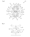
- FIG. 2 schematically a cross section of an engine 100 is shown, which is formed as a rotary piston engine 100. An enlarged section of this is in Fig. 3 shown.
- the rotary engine 100 comprises as essential components two rotary pistons 20 and 30, which are arranged in an inner space 11. This is limited by a housing inner wall 12 of a housing 10.
- a not shown inlet opening 13 allows exhaust gas flows into the interior 11.
- the inlet opening 13 is made with the first line arm Fig. 1 connected.
- On the interior 11 also has an outlet opening 15 for the exhaust gas is present. If the exhaust gas flows from the inlet opening 13 through the interior 11 to the outlet opening 15, it must pass through the two rotary pistons 20, 30 for this purpose and causes them to rotate.
- the axes of rotation of the two rotary pistons 20 and 30 are indicated.
- the axes of rotation 21, 31 extend into the plane of the drawing.
- the design of the rotary pistons 20, 30 is crucial. These are intended to provide a seal to one another and a seal to the surrounding housing inner wall 12, with which exhaust gas can not reach the outlet opening 15 when the rotary pistons 20, 30 are at a standstill.
- the rotary pistons 20, 30 are to be easily drivable by the exhaust gas, that is, they are already rotating at low pressure.
- the two rotary pistons 20 and 30 have at their respective outer sides via sealing strips 25, 26, 35, 36.
- the outer sides can be regarded as lateral surfaces of approximately cylindrical rotary pistons 20, 30.
- the sealing strips 25, 26, 35, 36 preferably extend over the entire height of the inner space 11, wherein the height can extend in the direction of the axes of rotation 21, 31.
- the rotary piston 20 has at least two, preferably exactly two, sealing strips 25, 26. Likewise, at least two, preferably exactly two, sealing strips 35, 36 are arranged on the rotary piston 30. The sealing strips 25, 26, 35, 36 project radially beyond the remaining outer circumference of the associated rotary piston 20, 30. The sealing strips 25, 26, 35, 36 are preferably received in grooves on the respective rotary piston 20, 30 and may preferably consist of a different material than the part of the rotary piston 20, 30, in which the grooves are formed. In particular, the sealing strips 25, 26, 35, 36 may consist of a deformable material. This may be, for example, rubber, resin or a plastic.
- the sealing strips 25, 26, 35, 36 can be slightly deformed by countercurrent exhaust gas and pressed against the housing inner wall 12.
- a particularly good seal to the housing inner wall 12 is achieved.
- the sealing strips 25, 26, 35, 36 but also consist of a rigid material, such as metal.
- the sealing strips 25, 26, 35, 36 may be accommodated with some freedom in their associated grooves, with which the exhaust pressure, the sealing strips 25, 26, 35, 36 can easily tilt.
- the sealing strips 25, 26, 35, 36 are also pressed sealingly against the housing inner wall 12.
- the two rotary pistons 20, 30 are arranged in the interior 11 so that they touch each other. As a result, an exhaust gas flow between the rotary piston is largely excluded.
- the rotation axes 21 and 31 may be parallel to each other. But it is also an inclination between the axes of rotation 21, 31 possible, as long as a largely sealing contact between the rotary piston 20, 30 is ensured.
- the rotary pistons 20, 30 at their respective outer circumference also each have a toothed rim 23, 33, which is rigidly connected to the remaining part of the associated rotary piston 20, 30.
- the two sprockets 23, 33 are sized and arranged so that they mesh. As a result, both sprockets 23, 33 rotate together and form hardly any voids between each other. Exhaust gas can therefore hardly pass between the two sprockets 23, 33.
- the rotary pistons 20 and 30 at their respective outer periphery recesses 27, 28 and 37, 38.
- the number of recesses 27, 28 of the first rotary piston 20 is equal to the number of sealing strips 35, 36 of the second rotary piston 30 is selected.
- the number of recesses 37, 38 of the second rotary piston 30 is equal to the number of sealing strips 25, 26 of the first rotary piston 20 is selected.
- the sealing strips 35, 36 of the second rotary piston 30 meet straight on the recesses 27, 28 of the first rotary piston 20.
- 30 in each 90 ° intervals a recess and a sealing strip alternate.
- the two sealing strips 25, 26 in an azimuth angle of 180 ° (That is, a 180 ° angle about the rotation axis 21 around) spaced from each other.
- the two recesses 27, 28 are also offset by an azimuth angle of 180 ° to each other and additionally offset in each case by an azimuth angle of 90 ° to the sealing strips 25, 26.
- a rotation angle is relevant, via the same sealing strip 25, 26 35, 36 causes a seal to the housing inner wall 12.
- This rotation angle can, as in Fig. 2 may be greater than 180 ° and, for example, between 185 ° and 240 °.
- the housing wall 12 at each of the rotary pistons has a circular section shape, wherein this shape forms a circular section of greater than 180 °, that forms more than a semicircle.
- sealing strips 25, 26 35, 36 are closer in Fig. 3 recognizable.
- the sealing strip 35 is shown there in its cross section.
- the sealing strip 35 may be shaped like a profile, that is over its length (in particular in the direction of the axis of rotation 31) have the same cross-sectional shape.
- the cross-sectional shape forms a sliding block.
- a collar 35C is formed toward the inner end of the sealing strip 35. This engages in a T-shaped depression / groove. This prevents that the sliding block 35 can unintentionally come loose in the radial direction from the groove of the rotary piston.
- Insertion and removal of the sliding block 35 is possible in the longitudinal direction, ie in the direction of the axis of rotation 31. Due to the formation as sliding blocks, the sealing strips are on the one hand easy to attach. On the other hand, replacement is also simplified. This is significant as it is due to the sealing Contact with the housing inner wall 12 to a gradual abrasion of the sealing strips 25, 26, 35, 36 can come and so an exchange may be required.
- a sealing strip 35 is shown, which protrudes radially from the toothed rim 33.
- the sealing strip 35 has a point of maximum radial extent, or an edge extending into the plane of the drawing (or extending in the direction of the axis of rotation 31). From this edge of the sealing strip 35 has a surface 35 A, which faces the incoming exhaust gas (this applies to rotational positions in which the sealing strip 35, the housing inner wall 12 contacted).
- the area 35A is also referred to as the exhaust gas contact side / upstream side 35A.
- the sealing strip 35 has another surface 35B, which is also referred to as the back 35B.
- the rear side 35B does not face the inflowing exhaust gas when the sealing strip 35 contacts the housing inner wall 12.
- the exhaust gas contact side 35A has a recess or a concave shape, while the rear side 35B has an outwardly curved or convex shape.
- the outer end of the sealing strip 35 so the radially outermost part deformed by the counterflowing exhaust gas transversely or approximately perpendicular to the radial direction.
- the sealing strip 35 is pressed against the housing inner wall 12.
- Fig. 3 the lower end of the sealing strip 35 is deformed approximately to the left and thus against the housing inner wall 12.
- a particularly good seal can be produced thereby, but without generating an unduly high friction between the sealing strips and the housing inner wall.
- the rotary pistons can therefore advantageously be set in rotation.
- exhaust gases with low pressure can be used for energy use.
- the sealing strips may also have shapes other than those described. So it may be sufficient if either the exhaust contact side or the back is formed as described. For example, the other side may be flat or shaped like the rest of the page. It is also possible that the forms of the exhaust gas contact side and the rear side are formed alone at an end portion of the sealing strip as described and not in the entire region which projects radially beyond the associated sprocket. In principle, suffice for sufficient sealing properties that the sealing strips and relative to the ring gear are deformable or movable and in particular are not formed integrally with the ring gear.
- the exhaust gas pressure generated by an internal combustion engine can be used to generate electrical energy. This is done with a motor, which is preferably formed by the rotary piston engine described.
Landscapes
- Engineering & Computer Science (AREA)
- Mechanical Engineering (AREA)
- General Engineering & Computer Science (AREA)
- Chemical & Material Sciences (AREA)
- Combustion & Propulsion (AREA)
- Engine Equipment That Uses Special Cycles (AREA)
- Exhaust Silencers (AREA)
Priority Applications (4)
| Application Number | Priority Date | Filing Date | Title |
|---|---|---|---|
| EP15186105.1A EP3144494B1 (fr) | 2015-09-21 | 2015-09-21 | Systeme de recuperation d'energie des gaz d'echappement et procede de recuperation d'energie des gaz d'echappement |
| PCT/EP2016/071725 WO2017050622A1 (fr) | 2015-09-21 | 2016-09-14 | Système de récupération d'énergie de gaz d'échappement et procédé de récupération d'énergie de gaz d'échappement |
| US15/761,214 US20180258818A1 (en) | 2015-09-21 | 2016-09-14 | Exhaust-gas energy recovery system and method for exhaust-gas energy recovery |
| ZA2018/01911A ZA201801911B (en) | 2015-09-21 | 2018-03-22 | Exhaust-gas energy recovery system and method for exhaust-gas energy recovery |
Applications Claiming Priority (1)
| Application Number | Priority Date | Filing Date | Title |
|---|---|---|---|
| EP15186105.1A EP3144494B1 (fr) | 2015-09-21 | 2015-09-21 | Systeme de recuperation d'energie des gaz d'echappement et procede de recuperation d'energie des gaz d'echappement |
Publications (2)
| Publication Number | Publication Date |
|---|---|
| EP3144494A1 true EP3144494A1 (fr) | 2017-03-22 |
| EP3144494B1 EP3144494B1 (fr) | 2018-11-07 |
Family
ID=54196815
Family Applications (1)
| Application Number | Title | Priority Date | Filing Date |
|---|---|---|---|
| EP15186105.1A Not-in-force EP3144494B1 (fr) | 2015-09-21 | 2015-09-21 | Systeme de recuperation d'energie des gaz d'echappement et procede de recuperation d'energie des gaz d'echappement |
Country Status (4)
| Country | Link |
|---|---|
| US (1) | US20180258818A1 (fr) |
| EP (1) | EP3144494B1 (fr) |
| WO (1) | WO2017050622A1 (fr) |
| ZA (1) | ZA201801911B (fr) |
Cited By (2)
| Publication number | Priority date | Publication date | Assignee | Title |
|---|---|---|---|---|
| EP3527781A1 (fr) | 2018-02-14 | 2019-08-21 | Fuelsave GmbH | Moteur à piston rotatif et procédé d'entraînement d'un moteur à piston rotatif |
| CN113833554A (zh) * | 2021-10-08 | 2021-12-24 | 黄宇骋 | 一种汽车尾气的热能和动能利用装置 |
Families Citing this family (1)
| Publication number | Priority date | Publication date | Assignee | Title |
|---|---|---|---|---|
| CN113755658B (zh) * | 2020-12-31 | 2022-10-11 | 厦门大学 | 一种基于钢铁厂余热利用的二次储能体系 |
Citations (3)
| Publication number | Priority date | Publication date | Assignee | Title |
|---|---|---|---|---|
| WO2008092218A1 (fr) * | 2007-02-02 | 2008-08-07 | Moreira Machado Cassio | Moteur à combustion interne avec temps allongé |
| US20120124992A1 (en) * | 2010-11-18 | 2012-05-24 | Fiveland Scott B | Fluid handling system having dedicated egr turbo-generator |
| GB2513432A (en) * | 2013-04-26 | 2014-10-29 | Controlled Power Technologies Ltd | Generation of electricity from exhaust gas |
Family Cites Families (13)
| Publication number | Priority date | Publication date | Assignee | Title |
|---|---|---|---|---|
| US2604051A (en) * | 1945-12-14 | 1952-07-22 | Keelavite Co Ltd | Rotary pump |
| US3744245A (en) * | 1971-06-21 | 1973-07-10 | D Kelly | Closed cycle rotary engine system |
| DE2635972A1 (de) * | 1976-08-10 | 1978-02-16 | Borsig Gmbh | Aussenachsige drehkolbenmaschine |
| US4646693A (en) * | 1983-04-18 | 1987-03-03 | Zachary Fayngersh | Rotary engine |
| DE3445979C1 (de) * | 1984-12-17 | 1986-01-30 | Kurt 8351 Lalling Jauch | Drehkolbenmaschine |
| US4971002A (en) * | 1989-01-26 | 1990-11-20 | Le Le K | Rotary internal combustion engine |
| US5154149A (en) * | 1991-04-05 | 1992-10-13 | Turner Leonard W | Rotary motor/pump |
| US8215935B2 (en) * | 2000-05-12 | 2012-07-10 | Gyroton Corporation | Multiple rotor fluid transfer engine |
| DE102007019958B4 (de) * | 2006-08-14 | 2011-11-10 | Ralf Hettrich | Vielzahndrehkolbenmotor mit extrem hohen Drehmoment bei niedrigsten als auch bei sehr hohen Drehzahlen wie in Bereichen einer Turbine, als Antrieb oder zum Einsatz der Energiegewinnung, Energieumwandlung oder Energierückgewinnung |
| US8181624B2 (en) * | 2006-09-05 | 2012-05-22 | Terry Michael Van Blaricom | Open-cycle internal combustion engine |
| US9322327B2 (en) * | 2009-11-03 | 2016-04-26 | Honeywell International Inc. | Turbocharger with bypass valve providing complete bypass of the turbine for improved catalyst light-off |
| US9435203B2 (en) * | 2010-10-22 | 2016-09-06 | Peter South | Rotary positive displacement machine |
| DE202013012076U1 (de) * | 2013-10-09 | 2015-03-11 | Ulrich Anton Busz | Rotationskolbenmaschine mit wenigstens zwei kreisförmigen Kolben |
-
2015
- 2015-09-21 EP EP15186105.1A patent/EP3144494B1/fr not_active Not-in-force
-
2016
- 2016-09-14 US US15/761,214 patent/US20180258818A1/en not_active Abandoned
- 2016-09-14 WO PCT/EP2016/071725 patent/WO2017050622A1/fr not_active Ceased
-
2018
- 2018-03-22 ZA ZA2018/01911A patent/ZA201801911B/en unknown
Patent Citations (3)
| Publication number | Priority date | Publication date | Assignee | Title |
|---|---|---|---|---|
| WO2008092218A1 (fr) * | 2007-02-02 | 2008-08-07 | Moreira Machado Cassio | Moteur à combustion interne avec temps allongé |
| US20120124992A1 (en) * | 2010-11-18 | 2012-05-24 | Fiveland Scott B | Fluid handling system having dedicated egr turbo-generator |
| GB2513432A (en) * | 2013-04-26 | 2014-10-29 | Controlled Power Technologies Ltd | Generation of electricity from exhaust gas |
Cited By (6)
| Publication number | Priority date | Publication date | Assignee | Title |
|---|---|---|---|---|
| EP3527781A1 (fr) | 2018-02-14 | 2019-08-21 | Fuelsave GmbH | Moteur à piston rotatif et procédé d'entraînement d'un moteur à piston rotatif |
| WO2019158449A1 (fr) | 2018-02-14 | 2019-08-22 | Fuelsave Gmbh | Moteur à pistons rotatifs et procédé pour faire fonctionner un moteur à pistons rotatifs |
| CN111954749A (zh) * | 2018-02-14 | 2020-11-17 | 燃料节省有限公司 | 旋转活塞发动机和用于操作旋转活塞发动机的方法 |
| US11098587B2 (en) * | 2018-02-14 | 2021-08-24 | Fuelsave Gmbh | Rotary piston engine and method for operating a rotary piston engine |
| CN111954749B (zh) * | 2018-02-14 | 2022-04-01 | 燃料节省有限公司 | 旋转活塞发动机和用于操作旋转活塞发动机的方法 |
| CN113833554A (zh) * | 2021-10-08 | 2021-12-24 | 黄宇骋 | 一种汽车尾气的热能和动能利用装置 |
Also Published As
| Publication number | Publication date |
|---|---|
| EP3144494B1 (fr) | 2018-11-07 |
| US20180258818A1 (en) | 2018-09-13 |
| ZA201801911B (en) | 2018-11-28 |
| WO2017050622A1 (fr) | 2017-03-30 |
Similar Documents
| Publication | Publication Date | Title |
|---|---|---|
| DE3690061C2 (de) | Rotationskolbenmaschine | |
| DE102007019958B4 (de) | Vielzahndrehkolbenmotor mit extrem hohen Drehmoment bei niedrigsten als auch bei sehr hohen Drehzahlen wie in Bereichen einer Turbine, als Antrieb oder zum Einsatz der Energiegewinnung, Energieumwandlung oder Energierückgewinnung | |
| EP3144494B1 (fr) | Systeme de recuperation d'energie des gaz d'echappement et procede de recuperation d'energie des gaz d'echappement | |
| DE112013006341T5 (de) | Abgas-Energierückgewinnungssystem | |
| EP1078148B1 (fr) | Dispositif pour le reglage de la position de phase d'un arbre | |
| WO2004056559A1 (fr) | Dispositif de compression | |
| EP3144471B1 (fr) | Moteur a piston rotatif et procede d'entrainement d'un moteur a piston rotatif | |
| DE842948C (de) | Waermeaustauscher | |
| DE102007054197A1 (de) | Antriebssystem für ein Fahrzeug | |
| DE112009003129B4 (de) | Gasturbine mit einer schaltbaren Solarheizeinrichtung | |
| EP2224125A2 (fr) | Dispositif de production d'énergie d'un flux | |
| EP3184758B1 (fr) | Installation de cogeneration et procede de fonctionnement d'une installation de cogeneration | |
| DE102007011443A1 (de) | Schließeinheit für ein Werkzeug | |
| DE2029832A1 (de) | Drehkolben Arbeitsmaschine | |
| DE2921311C2 (fr) | ||
| DE3330650A1 (de) | Stroemungskraftmaschine | |
| DE102013016658A1 (de) | Rotationskolbenmaschine mit wenigstens zwei kreisförmigen Kolben | |
| AT524617B1 (de) | Expansionsmaschine | |
| DE102007054321A1 (de) | Kolbenmaschine | |
| DE102015205737A1 (de) | Brennkraftmaschine mit Abgasenergienutzung und Verfahren zum Betrieb einer solchen Brennkraftmaschine | |
| EP3527781A1 (fr) | Moteur à piston rotatif et procédé d'entraînement d'un moteur à piston rotatif | |
| DE102006021928A1 (de) | Vorrichtung zur Erzeugung mechanischer Energie | |
| DE1576240A1 (de) | Vorrichtung zur Verwendung als Motor,insbesondere Hydraulikmotor,Verbrennungskraftmaschine,Pumpe u.dgl. | |
| DE333210C (de) | Umsteuerbare Turbine | |
| EP2527590A2 (fr) | Etendeur à ailettes |
Legal Events
| Date | Code | Title | Description |
|---|---|---|---|
| PUAI | Public reference made under article 153(3) epc to a published international application that has entered the european phase |
Free format text: ORIGINAL CODE: 0009012 |
|
| STAA | Information on the status of an ep patent application or granted ep patent |
Free format text: STATUS: THE APPLICATION HAS BEEN PUBLISHED |
|
| AK | Designated contracting states |
Kind code of ref document: A1 Designated state(s): AL AT BE BG CH CY CZ DE DK EE ES FI FR GB GR HR HU IE IS IT LI LT LU LV MC MK MT NL NO PL PT RO RS SE SI SK SM TR |
|
| AX | Request for extension of the european patent |
Extension state: BA ME |
|
| STAA | Information on the status of an ep patent application or granted ep patent |
Free format text: STATUS: REQUEST FOR EXAMINATION WAS MADE |
|
| 17P | Request for examination filed |
Effective date: 20170919 |
|
| RBV | Designated contracting states (corrected) |
Designated state(s): AL AT BE BG CH CY CZ DE DK EE ES FI FR GB GR HR HU IE IS IT LI LT LU LV MC MK MT NL NO PL PT RO RS SE SI SK SM TR |
|
| REG | Reference to a national code |
Ref country code: DE Ref legal event code: R079 Ref document number: 502015006761 Country of ref document: DE Free format text: PREVIOUS MAIN CLASS: F01N0005000000 Ipc: F01C0001120000 |
|
| RIC1 | Information provided on ipc code assigned before grant |
Ipc: F01C 11/00 20060101ALI20180130BHEP Ipc: F01C 21/00 20060101ALI20180130BHEP Ipc: F01N 5/00 20060101ALI20180130BHEP Ipc: F01C 1/12 20060101AFI20180130BHEP Ipc: F02G 5/04 20060101ALI20180130BHEP Ipc: F01N 5/04 20060101ALI20180130BHEP Ipc: F01N 5/02 20060101ALI20180130BHEP Ipc: F02B 41/10 20060101ALI20180130BHEP |
|
| GRAP | Despatch of communication of intention to grant a patent |
Free format text: ORIGINAL CODE: EPIDOSNIGR1 |
|
| STAA | Information on the status of an ep patent application or granted ep patent |
Free format text: STATUS: GRANT OF PATENT IS INTENDED |
|
| INTG | Intention to grant announced |
Effective date: 20180425 |
|
| GRAS | Grant fee paid |
Free format text: ORIGINAL CODE: EPIDOSNIGR3 |
|
| GRAA | (expected) grant |
Free format text: ORIGINAL CODE: 0009210 |
|
| STAA | Information on the status of an ep patent application or granted ep patent |
Free format text: STATUS: THE PATENT HAS BEEN GRANTED |
|
| AK | Designated contracting states |
Kind code of ref document: B1 Designated state(s): AL AT BE BG CH CY CZ DE DK EE ES FI FR GB GR HR HU IE IS IT LI LT LU LV MC MK MT NL NO PL PT RO RS SE SI SK SM TR |
|
| REG | Reference to a national code |
Ref country code: GB Ref legal event code: FG4D Free format text: NOT ENGLISH |
|
| REG | Reference to a national code |
Ref country code: CH Ref legal event code: EP Ref country code: AT Ref legal event code: REF Ref document number: 1062280 Country of ref document: AT Kind code of ref document: T Effective date: 20181115 |
|
| REG | Reference to a national code |
Ref country code: DE Ref legal event code: R096 Ref document number: 502015006761 Country of ref document: DE |
|
| REG | Reference to a national code |
Ref country code: IE Ref legal event code: FG4D Free format text: LANGUAGE OF EP DOCUMENT: GERMAN |
|
| REG | Reference to a national code |
Ref country code: NL Ref legal event code: MP Effective date: 20181107 |
|
| REG | Reference to a national code |
Ref country code: LT Ref legal event code: MG4D |
|
| PG25 | Lapsed in a contracting state [announced via postgrant information from national office to epo] |
Ref country code: FI Free format text: LAPSE BECAUSE OF FAILURE TO SUBMIT A TRANSLATION OF THE DESCRIPTION OR TO PAY THE FEE WITHIN THE PRESCRIBED TIME-LIMIT Effective date: 20181107 Ref country code: NO Free format text: LAPSE BECAUSE OF FAILURE TO SUBMIT A TRANSLATION OF THE DESCRIPTION OR TO PAY THE FEE WITHIN THE PRESCRIBED TIME-LIMIT Effective date: 20190207 Ref country code: IS Free format text: LAPSE BECAUSE OF FAILURE TO SUBMIT A TRANSLATION OF THE DESCRIPTION OR TO PAY THE FEE WITHIN THE PRESCRIBED TIME-LIMIT Effective date: 20190307 Ref country code: HR Free format text: LAPSE BECAUSE OF FAILURE TO SUBMIT A TRANSLATION OF THE DESCRIPTION OR TO PAY THE FEE WITHIN THE PRESCRIBED TIME-LIMIT Effective date: 20181107 Ref country code: LT Free format text: LAPSE BECAUSE OF FAILURE TO SUBMIT A TRANSLATION OF THE DESCRIPTION OR TO PAY THE FEE WITHIN THE PRESCRIBED TIME-LIMIT Effective date: 20181107 Ref country code: BG Free format text: LAPSE BECAUSE OF FAILURE TO SUBMIT A TRANSLATION OF THE DESCRIPTION OR TO PAY THE FEE WITHIN THE PRESCRIBED TIME-LIMIT Effective date: 20190207 Ref country code: ES Free format text: LAPSE BECAUSE OF FAILURE TO SUBMIT A TRANSLATION OF THE DESCRIPTION OR TO PAY THE FEE WITHIN THE PRESCRIBED TIME-LIMIT Effective date: 20181107 Ref country code: LV Free format text: LAPSE BECAUSE OF FAILURE TO SUBMIT A TRANSLATION OF THE DESCRIPTION OR TO PAY THE FEE WITHIN THE PRESCRIBED TIME-LIMIT Effective date: 20181107 |
|
| PG25 | Lapsed in a contracting state [announced via postgrant information from national office to epo] |
Ref country code: PT Free format text: LAPSE BECAUSE OF FAILURE TO SUBMIT A TRANSLATION OF THE DESCRIPTION OR TO PAY THE FEE WITHIN THE PRESCRIBED TIME-LIMIT Effective date: 20190307 Ref country code: AL Free format text: LAPSE BECAUSE OF FAILURE TO SUBMIT A TRANSLATION OF THE DESCRIPTION OR TO PAY THE FEE WITHIN THE PRESCRIBED TIME-LIMIT Effective date: 20181107 Ref country code: RS Free format text: LAPSE BECAUSE OF FAILURE TO SUBMIT A TRANSLATION OF THE DESCRIPTION OR TO PAY THE FEE WITHIN THE PRESCRIBED TIME-LIMIT Effective date: 20181107 Ref country code: NL Free format text: LAPSE BECAUSE OF FAILURE TO SUBMIT A TRANSLATION OF THE DESCRIPTION OR TO PAY THE FEE WITHIN THE PRESCRIBED TIME-LIMIT Effective date: 20181107 Ref country code: GR Free format text: LAPSE BECAUSE OF FAILURE TO SUBMIT A TRANSLATION OF THE DESCRIPTION OR TO PAY THE FEE WITHIN THE PRESCRIBED TIME-LIMIT Effective date: 20190208 Ref country code: SE Free format text: LAPSE BECAUSE OF FAILURE TO SUBMIT A TRANSLATION OF THE DESCRIPTION OR TO PAY THE FEE WITHIN THE PRESCRIBED TIME-LIMIT Effective date: 20181107 |
|
| PG25 | Lapsed in a contracting state [announced via postgrant information from national office to epo] |
Ref country code: IT Free format text: LAPSE BECAUSE OF FAILURE TO SUBMIT A TRANSLATION OF THE DESCRIPTION OR TO PAY THE FEE WITHIN THE PRESCRIBED TIME-LIMIT Effective date: 20181107 Ref country code: DK Free format text: LAPSE BECAUSE OF FAILURE TO SUBMIT A TRANSLATION OF THE DESCRIPTION OR TO PAY THE FEE WITHIN THE PRESCRIBED TIME-LIMIT Effective date: 20181107 Ref country code: PL Free format text: LAPSE BECAUSE OF FAILURE TO SUBMIT A TRANSLATION OF THE DESCRIPTION OR TO PAY THE FEE WITHIN THE PRESCRIBED TIME-LIMIT Effective date: 20181107 Ref country code: CZ Free format text: LAPSE BECAUSE OF FAILURE TO SUBMIT A TRANSLATION OF THE DESCRIPTION OR TO PAY THE FEE WITHIN THE PRESCRIBED TIME-LIMIT Effective date: 20181107 |
|
| REG | Reference to a national code |
Ref country code: CH Ref legal event code: NV Representative=s name: TR-IP CONSULTING LLC, CH |
|
| REG | Reference to a national code |
Ref country code: DE Ref legal event code: R097 Ref document number: 502015006761 Country of ref document: DE |
|
| PG25 | Lapsed in a contracting state [announced via postgrant information from national office to epo] |
Ref country code: SK Free format text: LAPSE BECAUSE OF FAILURE TO SUBMIT A TRANSLATION OF THE DESCRIPTION OR TO PAY THE FEE WITHIN THE PRESCRIBED TIME-LIMIT Effective date: 20181107 Ref country code: RO Free format text: LAPSE BECAUSE OF FAILURE TO SUBMIT A TRANSLATION OF THE DESCRIPTION OR TO PAY THE FEE WITHIN THE PRESCRIBED TIME-LIMIT Effective date: 20181107 Ref country code: EE Free format text: LAPSE BECAUSE OF FAILURE TO SUBMIT A TRANSLATION OF THE DESCRIPTION OR TO PAY THE FEE WITHIN THE PRESCRIBED TIME-LIMIT Effective date: 20181107 Ref country code: SM Free format text: LAPSE BECAUSE OF FAILURE TO SUBMIT A TRANSLATION OF THE DESCRIPTION OR TO PAY THE FEE WITHIN THE PRESCRIBED TIME-LIMIT Effective date: 20181107 |
|
| PLBE | No opposition filed within time limit |
Free format text: ORIGINAL CODE: 0009261 |
|
| STAA | Information on the status of an ep patent application or granted ep patent |
Free format text: STATUS: NO OPPOSITION FILED WITHIN TIME LIMIT |
|
| 26N | No opposition filed |
Effective date: 20190808 |
|
| PG25 | Lapsed in a contracting state [announced via postgrant information from national office to epo] |
Ref country code: SI Free format text: LAPSE BECAUSE OF FAILURE TO SUBMIT A TRANSLATION OF THE DESCRIPTION OR TO PAY THE FEE WITHIN THE PRESCRIBED TIME-LIMIT Effective date: 20181107 |
|
| REG | Reference to a national code |
Ref country code: CH Ref legal event code: PCAR Free format text: NEW ADDRESS: ROUTE DU COUTSET 18, 1485 NUVILLY (CH) |
|
| PG25 | Lapsed in a contracting state [announced via postgrant information from national office to epo] |
Ref country code: TR Free format text: LAPSE BECAUSE OF FAILURE TO SUBMIT A TRANSLATION OF THE DESCRIPTION OR TO PAY THE FEE WITHIN THE PRESCRIBED TIME-LIMIT Effective date: 20181107 |
|
| REG | Reference to a national code |
Ref country code: DE Ref legal event code: R119 Ref document number: 502015006761 Country of ref document: DE |
|
| PG25 | Lapsed in a contracting state [announced via postgrant information from national office to epo] |
Ref country code: MC Free format text: LAPSE BECAUSE OF FAILURE TO SUBMIT A TRANSLATION OF THE DESCRIPTION OR TO PAY THE FEE WITHIN THE PRESCRIBED TIME-LIMIT Effective date: 20181107 |
|
| REG | Reference to a national code |
Ref country code: CH Ref legal event code: PL |
|
| PG25 | Lapsed in a contracting state [announced via postgrant information from national office to epo] |
Ref country code: LU Free format text: LAPSE BECAUSE OF NON-PAYMENT OF DUE FEES Effective date: 20190921 Ref country code: CH Free format text: LAPSE BECAUSE OF NON-PAYMENT OF DUE FEES Effective date: 20190930 Ref country code: IE Free format text: LAPSE BECAUSE OF NON-PAYMENT OF DUE FEES Effective date: 20190921 Ref country code: LI Free format text: LAPSE BECAUSE OF NON-PAYMENT OF DUE FEES Effective date: 20190930 Ref country code: DE Free format text: LAPSE BECAUSE OF NON-PAYMENT OF DUE FEES Effective date: 20200401 |
|
| REG | Reference to a national code |
Ref country code: BE Ref legal event code: MM Effective date: 20190930 |
|
| PG25 | Lapsed in a contracting state [announced via postgrant information from national office to epo] |
Ref country code: BE Free format text: LAPSE BECAUSE OF NON-PAYMENT OF DUE FEES Effective date: 20190930 |
|
| GBPC | Gb: european patent ceased through non-payment of renewal fee |
Effective date: 20190921 |
|
| PG25 | Lapsed in a contracting state [announced via postgrant information from national office to epo] |
Ref country code: FR Free format text: LAPSE BECAUSE OF NON-PAYMENT OF DUE FEES Effective date: 20190930 Ref country code: GB Free format text: LAPSE BECAUSE OF NON-PAYMENT OF DUE FEES Effective date: 20190921 |
|
| PG25 | Lapsed in a contracting state [announced via postgrant information from national office to epo] |
Ref country code: CY Free format text: LAPSE BECAUSE OF FAILURE TO SUBMIT A TRANSLATION OF THE DESCRIPTION OR TO PAY THE FEE WITHIN THE PRESCRIBED TIME-LIMIT Effective date: 20181107 |
|
| PG25 | Lapsed in a contracting state [announced via postgrant information from national office to epo] |
Ref country code: MT Free format text: LAPSE BECAUSE OF FAILURE TO SUBMIT A TRANSLATION OF THE DESCRIPTION OR TO PAY THE FEE WITHIN THE PRESCRIBED TIME-LIMIT Effective date: 20181107 Ref country code: HU Free format text: LAPSE BECAUSE OF FAILURE TO SUBMIT A TRANSLATION OF THE DESCRIPTION OR TO PAY THE FEE WITHIN THE PRESCRIBED TIME-LIMIT; INVALID AB INITIO Effective date: 20150921 |
|
| REG | Reference to a national code |
Ref country code: AT Ref legal event code: MM01 Ref document number: 1062280 Country of ref document: AT Kind code of ref document: T Effective date: 20200921 |
|
| PG25 | Lapsed in a contracting state [announced via postgrant information from national office to epo] |
Ref country code: AT Free format text: LAPSE BECAUSE OF NON-PAYMENT OF DUE FEES Effective date: 20200921 |
|
| PG25 | Lapsed in a contracting state [announced via postgrant information from national office to epo] |
Ref country code: MK Free format text: LAPSE BECAUSE OF FAILURE TO SUBMIT A TRANSLATION OF THE DESCRIPTION OR TO PAY THE FEE WITHIN THE PRESCRIBED TIME-LIMIT Effective date: 20181107 |