EP3144513A1 - Kraftstoffeinspritzsteuerungsvorrichtung und kraftstoffeinspritzsteuerungsverfahren für einen verbrennungsmotor - Google Patents
Kraftstoffeinspritzsteuerungsvorrichtung und kraftstoffeinspritzsteuerungsverfahren für einen verbrennungsmotor Download PDFInfo
- Publication number
- EP3144513A1 EP3144513A1 EP14891693.5A EP14891693A EP3144513A1 EP 3144513 A1 EP3144513 A1 EP 3144513A1 EP 14891693 A EP14891693 A EP 14891693A EP 3144513 A1 EP3144513 A1 EP 3144513A1
- Authority
- EP
- European Patent Office
- Prior art keywords
- fuel injection
- cylinder
- fuel
- head
- timing
- Prior art date
- Legal status (The legal status is an assumption and is not a legal conclusion. Google has not performed a legal analysis and makes no representation as to the accuracy of the status listed.)
- Granted
Links
- 238000002347 injection Methods 0.000 title claims abstract description 202
- 239000007924 injection Substances 0.000 title claims abstract description 202
- 239000000446 fuel Substances 0.000 title claims abstract description 179
- 238000002485 combustion reaction Methods 0.000 title claims abstract description 27
- 238000000034 method Methods 0.000 title claims description 6
- 238000001816 cooling Methods 0.000 claims abstract description 75
- 239000002826 coolant Substances 0.000 claims abstract description 12
- 230000009467 reduction Effects 0.000 claims abstract description 12
- 239000000498 cooling water Substances 0.000 claims description 18
- 239000003921 oil Substances 0.000 claims description 17
- 238000001514 detection method Methods 0.000 claims description 9
- 239000010687 lubricating oil Substances 0.000 claims description 4
- XLYOFNOQVPJJNP-UHFFFAOYSA-N water Substances O XLYOFNOQVPJJNP-UHFFFAOYSA-N 0.000 description 44
- 230000006835 compression Effects 0.000 description 32
- 238000007906 compression Methods 0.000 description 32
- 230000007423 decrease Effects 0.000 description 10
- 238000010586 diagram Methods 0.000 description 8
- 238000001704 evaporation Methods 0.000 description 6
- 230000008020 evaporation Effects 0.000 description 6
- 230000007246 mechanism Effects 0.000 description 6
- 230000000694 effects Effects 0.000 description 4
- 238000004364 calculation method Methods 0.000 description 3
- 230000008859 change Effects 0.000 description 3
- 238000006243 chemical reaction Methods 0.000 description 2
- 230000008569 process Effects 0.000 description 2
- 230000000979 retarding effect Effects 0.000 description 2
- 230000009471 action Effects 0.000 description 1
- 230000005540 biological transmission Effects 0.000 description 1
- 230000015556 catabolic process Effects 0.000 description 1
- 238000006731 degradation reaction Methods 0.000 description 1
- 238000009792 diffusion process Methods 0.000 description 1
- 238000010790 dilution Methods 0.000 description 1
- 239000012895 dilution Substances 0.000 description 1
- 239000010720 hydraulic oil Substances 0.000 description 1
- 230000006872 improvement Effects 0.000 description 1
- 230000002265 prevention Effects 0.000 description 1
- 230000001737 promoting effect Effects 0.000 description 1
- 230000001629 suppression Effects 0.000 description 1
- 238000010792 warming Methods 0.000 description 1
Images


Classifications
-
- F—MECHANICAL ENGINEERING; LIGHTING; HEATING; WEAPONS; BLASTING
- F02—COMBUSTION ENGINES; HOT-GAS OR COMBUSTION-PRODUCT ENGINE PLANTS
- F02D—CONTROLLING COMBUSTION ENGINES
- F02D41/00—Electrical control of supply of combustible mixture or its constituents
- F02D41/30—Controlling fuel injection
- F02D41/32—Controlling fuel injection of the low pressure type
- F02D41/34—Controlling fuel injection of the low pressure type with means for controlling injection timing or duration
-
- F—MECHANICAL ENGINEERING; LIGHTING; HEATING; WEAPONS; BLASTING
- F02—COMBUSTION ENGINES; HOT-GAS OR COMBUSTION-PRODUCT ENGINE PLANTS
- F02D—CONTROLLING COMBUSTION ENGINES
- F02D41/00—Electrical control of supply of combustible mixture or its constituents
- F02D41/30—Controlling fuel injection
- F02D41/3005—Details not otherwise provided for
-
- F—MECHANICAL ENGINEERING; LIGHTING; HEATING; WEAPONS; BLASTING
- F01—MACHINES OR ENGINES IN GENERAL; ENGINE PLANTS IN GENERAL; STEAM ENGINES
- F01P—COOLING OF MACHINES OR ENGINES IN GENERAL; COOLING OF INTERNAL-COMBUSTION ENGINES
- F01P3/00—Liquid cooling
- F01P3/02—Arrangements for cooling cylinders or cylinder heads
-
- F—MECHANICAL ENGINEERING; LIGHTING; HEATING; WEAPONS; BLASTING
- F01—MACHINES OR ENGINES IN GENERAL; ENGINE PLANTS IN GENERAL; STEAM ENGINES
- F01P—COOLING OF MACHINES OR ENGINES IN GENERAL; COOLING OF INTERNAL-COMBUSTION ENGINES
- F01P7/00—Controlling of coolant flow
- F01P7/14—Controlling of coolant flow the coolant being liquid
- F01P7/16—Controlling of coolant flow the coolant being liquid by thermostatic control
- F01P7/165—Controlling of coolant flow the coolant being liquid by thermostatic control characterised by systems with two or more loops
-
- F—MECHANICAL ENGINEERING; LIGHTING; HEATING; WEAPONS; BLASTING
- F02—COMBUSTION ENGINES; HOT-GAS OR COMBUSTION-PRODUCT ENGINE PLANTS
- F02D—CONTROLLING COMBUSTION ENGINES
- F02D41/00—Electrical control of supply of combustible mixture or its constituents
- F02D41/02—Circuit arrangements for generating control signals
- F02D41/04—Introducing corrections for particular operating conditions
- F02D41/047—Taking into account fuel evaporation or wall wetting
-
- F—MECHANICAL ENGINEERING; LIGHTING; HEATING; WEAPONS; BLASTING
- F02—COMBUSTION ENGINES; HOT-GAS OR COMBUSTION-PRODUCT ENGINE PLANTS
- F02D—CONTROLLING COMBUSTION ENGINES
- F02D41/00—Electrical control of supply of combustible mixture or its constituents
- F02D41/22—Safety or indicating devices for abnormal conditions
-
- F—MECHANICAL ENGINEERING; LIGHTING; HEATING; WEAPONS; BLASTING
- F02—COMBUSTION ENGINES; HOT-GAS OR COMBUSTION-PRODUCT ENGINE PLANTS
- F02D—CONTROLLING COMBUSTION ENGINES
- F02D41/00—Electrical control of supply of combustible mixture or its constituents
- F02D41/24—Electrical control of supply of combustible mixture or its constituents characterised by the use of digital means
- F02D41/26—Electrical control of supply of combustible mixture or its constituents characterised by the use of digital means using computer, e.g. microprocessor
- F02D41/263—Electrical control of supply of combustible mixture or its constituents characterised by the use of digital means using computer, e.g. microprocessor the program execution being modifiable by physical parameters
-
- F—MECHANICAL ENGINEERING; LIGHTING; HEATING; WEAPONS; BLASTING
- F02—COMBUSTION ENGINES; HOT-GAS OR COMBUSTION-PRODUCT ENGINE PLANTS
- F02D—CONTROLLING COMBUSTION ENGINES
- F02D41/00—Electrical control of supply of combustible mixture or its constituents
- F02D41/30—Controlling fuel injection
- F02D41/32—Controlling fuel injection of the low pressure type
- F02D41/34—Controlling fuel injection of the low pressure type with means for controlling injection timing or duration
- F02D41/345—Controlling injection timing
-
- F—MECHANICAL ENGINEERING; LIGHTING; HEATING; WEAPONS; BLASTING
- F02—COMBUSTION ENGINES; HOT-GAS OR COMBUSTION-PRODUCT ENGINE PLANTS
- F02D—CONTROLLING COMBUSTION ENGINES
- F02D41/00—Electrical control of supply of combustible mixture or its constituents
- F02D41/30—Controlling fuel injection
- F02D41/38—Controlling fuel injection of the high pressure type
- F02D41/40—Controlling fuel injection of the high pressure type with means for controlling injection timing or duration
- F02D41/402—Multiple injections
-
- F—MECHANICAL ENGINEERING; LIGHTING; HEATING; WEAPONS; BLASTING
- F01—MACHINES OR ENGINES IN GENERAL; ENGINE PLANTS IN GENERAL; STEAM ENGINES
- F01P—COOLING OF MACHINES OR ENGINES IN GENERAL; COOLING OF INTERNAL-COMBUSTION ENGINES
- F01P3/00—Liquid cooling
- F01P3/02—Arrangements for cooling cylinders or cylinder heads
- F01P2003/027—Cooling cylinders and cylinder heads in parallel
-
- F—MECHANICAL ENGINEERING; LIGHTING; HEATING; WEAPONS; BLASTING
- F02—COMBUSTION ENGINES; HOT-GAS OR COMBUSTION-PRODUCT ENGINE PLANTS
- F02D—CONTROLLING COMBUSTION ENGINES
- F02D13/00—Controlling the engine output power by varying inlet or exhaust valve operating characteristics, e.g. timing
- F02D13/02—Controlling the engine output power by varying inlet or exhaust valve operating characteristics, e.g. timing during engine operation
- F02D13/0223—Variable control of the intake valves only
- F02D13/0234—Variable control of the intake valves only changing the valve timing only
-
- F—MECHANICAL ENGINEERING; LIGHTING; HEATING; WEAPONS; BLASTING
- F02—COMBUSTION ENGINES; HOT-GAS OR COMBUSTION-PRODUCT ENGINE PLANTS
- F02D—CONTROLLING COMBUSTION ENGINES
- F02D2200/00—Input parameters for engine control
- F02D2200/02—Input parameters for engine control the parameters being related to the engine
- F02D2200/021—Engine temperature
-
- F—MECHANICAL ENGINEERING; LIGHTING; HEATING; WEAPONS; BLASTING
- F02—COMBUSTION ENGINES; HOT-GAS OR COMBUSTION-PRODUCT ENGINE PLANTS
- F02D—CONTROLLING COMBUSTION ENGINES
- F02D2250/00—Engine control related to specific problems or objectives
- F02D2250/14—Timing of measurement, e.g. synchronisation of measurements to the engine cycle
-
- Y—GENERAL TAGGING OF NEW TECHNOLOGICAL DEVELOPMENTS; GENERAL TAGGING OF CROSS-SECTIONAL TECHNOLOGIES SPANNING OVER SEVERAL SECTIONS OF THE IPC; TECHNICAL SUBJECTS COVERED BY FORMER USPC CROSS-REFERENCE ART COLLECTIONS [XRACs] AND DIGESTS
- Y02—TECHNOLOGIES OR APPLICATIONS FOR MITIGATION OR ADAPTATION AGAINST CLIMATE CHANGE
- Y02T—CLIMATE CHANGE MITIGATION TECHNOLOGIES RELATED TO TRANSPORTATION
- Y02T10/00—Road transport of goods or passengers
- Y02T10/10—Internal combustion engine [ICE] based vehicles
- Y02T10/40—Engine management systems
Definitions
- the present invention relates to a fuel injection control device and a fuel injection control method for an internal combustion engine.
- Increasing the compression ratio is an effective measure to improve the thermal efficiency of an internal combustion engine to improve the fuel efficiency.
- knocking becomes more likely to occur as the compression ratio is increased and, thus, it becomes necessary to take measures to suppress the knocking.
- retarding the ignition timing is a known method to suppress knocking, but the torque is reduced as the ignition timing is retarded. That is, by retarding the ignition timing, the torque that should be obtainable through achieving a high compression ratio cannot be obtained.
- JP2012-102654A in order to achieve a high compression ratio while suppressing knocking, the final injection of a multi-stage injection internal combustion engine that carries out a multi-stage injection of fuel, is carried out in a compression stroke when in a low speed region in which knocking is likely to occur.
- the object of this control is to reduce the gas temperature in a cylinder by the evaporative latent heat of the fuel that is injected in the compression stroke.
- the compression stroke is a compression in a state in which the intake valve and the exhaust valve are closed, which can be considered as an adiabatic compression stroke. If fuel is injected in the course of such an adiabatic compression stroke, while a decrease in the gas temperature inside the cylinder due to evaporative latent heat does occur, the effect of reducing the gas temperature inside the cylinder near the top dead center in which knocking is likely to occur is small. In other words, there is room for improvement in the control of the above-described document, as a control for suppressing knocking.
- the object of the present invention is to carry out a fuel injection control that is capable of more reliably suppressing knocking.
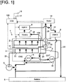
- FIG. 1 is a block diagram illustrating one example of a cooling system to which is applied the present embodiment.
- the present cooling system cools an internal combustion engine 1 by circulating cooling water using a water pump 5 that is driven by a spark-ignition internal combustion engine having direct fuel injection into a cylinder (hereinafter also simply referred to as "internal combustion engine") 1.
- the water pump 5 may be an electric pump that is driven by an electric motor as well.
- the cooling water channel inside the internal combustion engine 1 is branched into two lines, a head-side cooling channel 21 provided in a cylinder head 2, and a block-side cooling channel 22 provided in a cylinder block 3.
- a first control valve 13 is disposed on the cylinder head outlet side of the head-side cooling channel 21, and a second control valve 14 is provided on the cylinder block outlet side of the block-side cooling channel 22.
- a head-side water temperature sensor 12A is disposed between the cylinder head outlet of the head-side cooling channel 21 and the first control valve 13 for detecting the water temperature of the head-side cooling channel 21 (hereinafter also referred to as "head-side water temperature”).
- a block-side water temperature sensor 12B is disposed between the cylinder block outlet of the block-side cooling channel 22 and the second control valve 14 for detecting the water temperature of the block-side cooling channel 22 (hereinafter also referred to as "block-side water temperature”).
- the detection signals of the head-side water temperature sensor 12A and the block-side water temperature sensor 12B are sent to a controller 100, to be described later.
- a heater passage 25 connected to a heater core 10, a connection passage 28 connected to the second control valve 14, and a radiator passage 23 connected to the radiator 6 are connected to the first control valve 13, and it is possible to communicate with the head-side cooling channel 21 by selecting one of these passages. Additionally, it is possible to restrict the flow of cooling water in the head-side cooling channel 21 by closing the first control valve 13.
- an engine-side return passage 24 and a connection passage 28 that are connected to an oil cooler 15 and an oil warmer 16, are connected to the second control valve 14, and it is possible to communicate with the block-side cooling channel 22 by selecting one of these passages. Additionally, it is possible to restrict the flow of cooling water in the block-side cooling channel 22 by closing the second control valve 14.
- the first control valve 13 and the second control valve 14 are both controlled by the controller 100, described later.
- the second control valve 14 may also be a thermostat valve in order to simplify the system.
- the heater passage 25 is a passage for supplying cooling water to the heater core 10.
- a heater-side return passage 27 is connected to the heater core 10 for returning the cooling water that has undergone heat exchange with air in the heater core 10 to the water pump 5.
- An EGR cooler 9 is interposed in the heater-side return passage 27 for cooling EGR gas.
- the engine-side return passage 24 is a passage that links the second control valve 14 and the water pump 5, and a portion thereof is branched.
- An oil cooler 15 is connected to one of the branches for cooling the lubricating oil of the internal combustion engine 1, and an oil warmer 16 is connected to the other of the branches for warming the hydraulic oil of the automatic transmission 4.
- the radiator passage 23 is a passage links the first control valve 13 and the water pump 5, with a radiator 6 is interposed in an intermediate position thereof.
- a throttle-side passage 26 is branched from the head-side cooling channel 21 for merging with the heater-side return passage 27 via a throttle chamber 7 and an EGR valve 8.
- the cylinder head 2 has an oil temperature sensor 11 that detects the lubricating oil temperature in an oil jacket provided in the cylinder head. The detection signal of the oil temperature sensor 11 is sent to the controller 100.
- the controller 100 is configured from a microcomputer comprising a central processing unit (CPU), a read only memory (ROM), a random access memory (RAM), and an input/output interface (I/O interface).
- the controller 100 can be configured from a plurality of microcomputers as well.
- the controller 100 also receives detection signals from an accelerator pedal opening amount sensor 17 that detects the amount the driver opens the accelerator pedal, and a crank angle sensor 18 that detects the rotational speed of the internal combustion engine 1. Then, the controller 100 executes control of the opening amount of the throttle chamber 7 and the EGR valve 8, fuel injection control of the internal combustion engine 1, ignition timing control, control of the first control valve 13 and the second control valve 14, and the like, based on these detection signals.
- the controller 100 respectively infers the wall temperature of the cylinder head 2 (hereinafter also referred to as "head-side wall temperature”) based on the head-side water temperature, and the wall temperature of the cylinder block 3 (hereinafter also referred to as "block-side wall temperature”) based on the block-side water temperature.
- head-side wall temperature the wall temperature of the cylinder head 2
- block-side wall temperature the wall temperature of the cylinder block 3
- the controller 100 closes the first control valve 13 and the second control valve 14 to restrict the flow of cooling water of the head-side cooling channel 21 and the block-side cooling channel 22. A rise in the cooling water temperature is thereby promoted.
- the controller 100 opens the first control valve 13 and the second control valve 14. At this time, the controller 100 determines whether to flow the cooling water to the radiator passage 23 or to the engine-side return passage 24 according to the head-side water temperature and the block-side water temperature, and controls the first control valve 13 and the second control valve 14.
- the threshold values of the head-side wall temperature and the block-side wall temperature are set to 80 °C; the threshold values of the head-side water temperature and the block-side water temperature are set to 80 °C; and the threshold value of the oil temperature is set to 80 °C; if all of the temperatures described above are greater than or equal to the threshold values the state is considered to be the warm-up state; otherwise, the state is considered to be the cold engine state.
- the cold engine state a state in which the head-side wall temperature and the head-side water temperature are greater than or equal to 80 °C and the oil temperature is less than 80 °C is considered to be a high water temperature state.
- controller 100 constitutes a fuel injection timing setting means for setting the mode of fuel injection according to the state of the internal combustion engine 1.
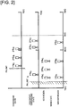
- FIG. 2 is a schematic diagram illustrating the modes of the fuel injection control according to the state of the internal combustion engine 1 in the case of a three-stage injection.
- the "fuel injection timing” in the following description refers to the timing at which fuel injection is started.
- the cold engine state excluding the high water temperature state (hereinafter simply referred to as the cold engine state), in order to reduce the amount of emission particulates (PN: Particulate Number), the advance angle of the fuel injection (PN limit) is retarded compared to the other states so as to reduce the adhesion of fuel to the piston and the cylinder wall. Additionally, each injection of the three-stage injection is configured to be at a fuel injection timing that prioritizes suppression of oil dilution by the fuel.
- the controller 100 blocks the circulation of cooling water in the head-side cooling channel 21 and the block-side cooling channel 22. A temperature rise in the head-side wall and the block-side wall is thereby promoted. In addition, a rise in the temperatures of the cooling water of the head-side cooling channel 21 and the block-side cooling channel 22 is also promoted.
- the mode of fuel injection differs depending on whether or not an EGR control is executed. If executing an EGR control, since knocking is less likely to occur due to the EGR control, the fuel injection timing is set so that fuel injection is completed three times on the advance side of bottom dead center, in order to take a longer mixing time for the in-cylinder gas. Additionally, if an EGR control is not to be executed, in order to secure the mixing time and reduce the gas temperature inside the cylinder, the second and third fuel injection timings are retarded compared to when an EGR control is executed. In particular, the third fuel injection timing is set between the bottom dead center and the intake valve closing timing.
- the present embodiment is characterized in the fuel injection control in the high water temperature state described below.
- the high water temperature state is a state in which the oil temperature has not risen to the warm-up state temperature, despite the head-side wall temperature and the block-side wall temperature having risen to the warm-up state temperature. Since the friction of each part is increased and the fuel efficiency is reduced as the oil temperature is reduced, it is desirable to promote a rise in the oil temperature when in the high water temperature state. If cooling water is circulated, the head-side wall temperature and the block-side wall temperature are reduced and a rise in the oil temperature is inhibited; therefore, in the high water temperature state, the controller 100 stops the circulation of water in at least the block-side cooling channel 22.
- the controller 100 carries out the second fuel injection and the third fuel injection of the three-stage injection between the bottom dead center and the intake valve closing timing, for example, as illustrated in Figure 2 .
- the gas temperature inside the cylinder is reduced due to the evaporative latent heat of the fuel.
- the second fuel injection and the third fuel injection are set to be closer to the intake valve closing timing, as described above.
- the third fuel injection timing is set so that the intake valve closing timing will be when a reduction in the gas temperature is occurring inside the cylinder, due to the evaporative latent heat of the fuel of the third injection. As described below, this is because the reduction margin of the gas temperature inside the cylinder at the intake valve closing timing is further amplified at the compression top dead center.
- the fuel injection timing described above is referred to as the fuel injection timing for cooling the inside of the cylinder.
- Figure 3 is a graph illustrating changes in the gas temperature inside the cylinder in a compression stroke; an enlarged view is provided for the vicinity of the intake valve closing timing (IVC in the figure) and the compression top dead center (TDC in the figure).
- compression stroke in the present embodiment refers to the interval from the time the intake valve closes to the time the exhaust valve opens.
- T is the gas temperature inside the cylinder
- V is the combustion chamber volume
- k is the specific heat ratio
- ⁇ is the compression ratio
- the gas temperature inside the cylinder at the compression top dead center becomes about twice the gas temperature inside the cylinder at the intake valve closing timing. Then, the temperature difference at the intake valve closing timing is amplified to twice at the compression top dead center. That is, if the gas temperature inside the cylinder is reduced at the intake valve closing timing, the decrease in the temperature at the compression top dead center is doubled.
- fuel injection control is carried out so that the reduction of the gas temperature inside the cylinder at the intake valve closing timing is greater.
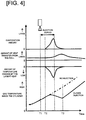
- Figure 4 is an example of a timing chart when the gas temperature inside the cylinder is reduced by the evaporative latent heat of the fuel.
- the term “Wall” in the figure refers to the head-side wall surface and the block-side wall surface.
- the "evaporation amount,” the “amount of heat transfer from the wall,” and the “amount of temperature change by the latent heat” are amounts at each timing. Therefore, the area surrounded by each chart and the horizontal axis corresponds to the amount that affects the gas temperature inside the cylinder.
- the injected fuel begins to evaporate from timing T2 after a time lag.
- the evaporation amount is gradually increased with the increase in the fuel amount in the cylinder and the progress of the diffusion of the fuel. Then, the evaporation amount decreases with a decrease in the amount of unevaporated fuel and the stopping of fuel injection.
- the amount of temperature change by the latent heat will display the same behavior as the behavior of the evaporation amount described above.
- the direction of temperature change will be in a direction to reduce the gas temperature inside the cylinder.
- the gas temperature inside the cylinder will thereby start to decrease.
- a delay occurs between when the evaporation starts and when the gas temperature inside the cylinder starts to decrease.
- the amount of heat that is transferred from the wall will also affect the gas temperature inside the cylinder.
- the amount of heat transfer from the wall is increased as the difference between the gas temperature inside the cylinder and the wall temperature is increased. In other words, if the gas temperature inside the cylinder is reduced by the evaporative latent heat, the amount of heat transfer from the wall is increased after a time lag.
- the gas temperature inside the cylinder that is reduced by the evaporative latent heat is thereafter increased by the heat transfer from the wall.
- the controller 100 sets the start timing of the third fuel injection of Figure 2 so that a timing T3 immediately before the gas temperature inside the cylinder turns to an increase coincides with the intake valve closing timing.
- the second fuel injection and the third fuel injection of the three-stage injection are set close to the intake valve closing timing, and, in particular, the third fuel injection timing is set as described above. If the gap between the second fuel injection and the third fuel injection is narrowed, the third fuel injection will be carried out in a state in which the gas temperature inside the cylinder is being reduced by the second fuel injection; therefore, the gas temperature inside the cylinder at the intake valve closing timing can be effectively reduced.
- the fuel injection mode for reducing the gas temperature inside the cylinder at the intake valve closing timing is not limited to the above.
- the fuel injection timing of the single-stage injection is set to the timing described above.
- the amount of heat transfer from the wall is increased due to an increase in the time period during which the fuel evaporates, the reduction margin of the gas temperature inside the cylinder due to the evaporative latent heat is increased, with the fuel injection amount per one injection becoming greater than in a multi-stage injection.
- it may be configured to switch to a single-stage injection when in the high water temperature state.
- weighted center of the multi-stage injection may be set to be at the intake valve closing timing, as illustrated in Figure 6 .
- weighted center of injection will be described with reference to Figure 7 .
- FIG. 7 is a schematic diagram illustrating a fuel injection pulse of a four-stage injection.
- IT1 - IT4 is the start timing of each fuel injection
- T inj 1 - T inj 4 is the fuel injection period (injection pulse width) of each fuel injection.
- IT1mid - IT4mid is the midpoint of each fuel injection period.
- ITc T inj 1 ⁇ IT 1 mid + T inj 2 ⁇ IT 2 mid + T inj 3 ⁇ IT 3 mid + T inj 4 ⁇ IT 4 mid T inj total
- T inj total is the total value of the injection pulse widths.
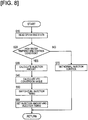
- Figure 8 is a flowchart illustrating the control routine of a fuel injection control that is executed by the controller 100.
- Step S10 the controller 100 reads the driving state. Specifically, the detection signal of the crank angle sensor 18 is read as the engine rotational speed, and the detection signal of the accelerator pedal opening amount sensor 17 is read as the load.
- Step S20 the controller 100 determines whether or not the state is a high water temperature state. The determination is carried out based on the above-described threshold value. If in a high water temperature state, the process of Step S30 is executed, and if not in the high water temperature state, the process of Step S70 is executed. In Step S70, the controller 100 executes a normal fuel injection control; that is, a fuel injection control for a cold engine state when in a cold engine state, and for a warm-up state when in a warm-up state.
- Step S30 the controller 100 calculates the fuel injection amount.
- a well-known calculation method is used for calculating the fuel injection amount. That is, a fuel injection amount map having the engine rotational speed and the load as parameters is created in advance, and the map is searched for the engine rotational speed and the load that are read in Step S10.
- Step S40 the controller 100 calculates the conversion angle of a variable valve mechanism VTC.
- the variable valve mechanism VTC is a mechanism that variably controls the opening and closing timing of the intake valves.
- the variable valve mechanism VTC used in the present embodiment is well-known; therefore, a description of the configuration of the variable valve mechanism VTC is omitted.
- a conversion angle map is created in advance having, as parameters, the engine rotational speed and the load as the driving states, and the controller 100 searches the map using the driving state that has been read. If a variable valve mechanism VTC is not provided, the present step is omitted.
- Step S50 the controller 100 switches the fuel injection timing to a timing corresponding to the high water temperature state described above.
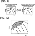
- the map is switched from the injection timing map for the cold engine state to the injection timing map for the high water temperature state, as illustrated in Figure 9 .
- the injection timing that is suitable for each driving state is assigned, using as parameters the engine rotational speed and the load as the driving states.
- an injection timing map is prepared for each injection. Then, the fuel injection start timing is calculated from the fuel injection timing map for the high water temperature state.
- the ignition timing for the high water temperature state may be calculated by arithmetic only in the operation region in which knocking is likely to occur, instead of switching the ignition timing map.
- the shaded region in the ignition timing map for the cold engine state of Figure 10 be the operation region in which knocking is likely to occur.
- IVC is the intake valve closing timing
- Tevap is the time that is required from when the temperature starts to decrease due to the evaporative latent heat, until the temperature decrease amount becomes the maximum.
- the ignition timing for the high water temperature state may be calculated only in an operation region in which knocking is likely to occur.
- Step S60 the controller 100 sets the fuel injection amount obtained in Step S30 and the fuel injection start timing obtained in Step S50 as the present fuel injection amount and fuel injection start timing.
- the circulation of the cooling water of the block-side cooling channel 22 may be configured to stop if the water temperature of the block-side cooling channel 22 becomes lower than, for example, 95°C, even after entering the warm-up state. This is to suppress a decrease in the fuel efficiency by increasing the temperature of the cylinder block 3 to reduce the friction between the piston and the cylinder wall. In this case, knocking is likely to occur due to the increase in temperature of the cylinder block 3; therefore, knocking is prevented by executing the fuel injection control in the high water temperature state described above.
Landscapes
- Engineering & Computer Science (AREA)
- Chemical & Material Sciences (AREA)
- Combustion & Propulsion (AREA)
- Mechanical Engineering (AREA)
- General Engineering & Computer Science (AREA)
- Computer Hardware Design (AREA)
- Microelectronics & Electronic Packaging (AREA)
- Electrical Control Of Air Or Fuel Supplied To Internal-Combustion Engine (AREA)
- Combined Controls Of Internal Combustion Engines (AREA)
- Fuel-Injection Apparatus (AREA)
- Cylinder Crankcases Of Internal Combustion Engines (AREA)
- Output Control And Ontrol Of Special Type Engine (AREA)
Applications Claiming Priority (1)
| Application Number | Priority Date | Filing Date | Title |
|---|---|---|---|
| PCT/JP2014/063002 WO2015173937A1 (ja) | 2014-05-15 | 2014-05-15 | 内燃機関の燃料噴射制御装置及び燃料噴射制御方法 |
Publications (3)
| Publication Number | Publication Date |
|---|---|
| EP3144513A1 true EP3144513A1 (de) | 2017-03-22 |
| EP3144513A4 EP3144513A4 (de) | 2017-05-03 |
| EP3144513B1 EP3144513B1 (de) | 2019-12-04 |
Family
ID=54479506
Family Applications (1)
| Application Number | Title | Priority Date | Filing Date |
|---|---|---|---|
| EP14891693.5A Active EP3144513B1 (de) | 2014-05-15 | 2014-05-15 | Kraftstoffeinspritzsteuerungsvorrichtung und kraftstoffeinspritzsteuerungsverfahren für einen verbrennungsmotor |
Country Status (8)
| Country | Link |
|---|---|
| US (1) | US10047693B2 (de) |
| EP (1) | EP3144513B1 (de) |
| JP (1) | JP6057021B2 (de) |
| CN (1) | CN106460714B (de) |
| MX (1) | MX361832B (de) |
| MY (1) | MY191525A (de) |
| RU (1) | RU2657011C1 (de) |
| WO (1) | WO2015173937A1 (de) |
Families Citing this family (7)
| Publication number | Priority date | Publication date | Assignee | Title |
|---|---|---|---|---|
| JP2017078344A (ja) * | 2015-10-19 | 2017-04-27 | トヨタ自動車株式会社 | 内燃機関の制御装置 |
| DE102015015362A1 (de) * | 2015-11-28 | 2017-06-01 | Daimler Ag | Verfahren zum Betreiben einer Verbrennungskraftmaschine, insbesondere eines Kraftwagens |
| MX367000B (es) * | 2016-02-12 | 2019-08-02 | Nissan Motor | Metodo de control y dispositivo de control de motor de combustion interna de inyeccion directa. |
| DE102016203436B4 (de) * | 2016-03-02 | 2017-11-30 | Continental Automotive Gmbh | Verfahren und Vorrichtung zum Ermitteln eines Einspritzzeitpunkts zum Einspritzen eines Kraftstoffs |
| JP6654594B2 (ja) * | 2017-03-16 | 2020-02-26 | ヤンマー株式会社 | エンジンシステム |
| WO2021011528A1 (en) | 2019-07-15 | 2021-01-21 | The Research Foundation For The State University Of New York | Method for control of advanced combustion through split direct injection of high heat of vaporization fuel or water fuel mixtures |
| GB2619025B (en) * | 2022-05-23 | 2024-06-05 | Phinia Delphi Luxembourg Sarl | Method of operating a hydrogen internal combustion engine |
Family Cites Families (16)
| Publication number | Priority date | Publication date | Assignee | Title |
|---|---|---|---|---|
| JP2712711B2 (ja) * | 1990-02-16 | 1998-02-16 | 株式会社デンソー | 内燃機関の冷却方法及びその装置 |
| RU2007593C1 (ru) * | 1990-11-19 | 1994-02-15 | Сагаков Станислав Святославович | Способ работы двигателя внутреннего сгорания |
| JP3553765B2 (ja) * | 1997-06-27 | 2004-08-11 | 株式会社日本自動車部品総合研究所 | 筒内直接噴射内燃機関 |
| JP2000054884A (ja) * | 1998-08-10 | 2000-02-22 | Toyota Central Res & Dev Lab Inc | 筒内噴射式内燃機関の燃料噴射制御方法 |
| DE10061546B4 (de) * | 2000-12-11 | 2011-07-21 | Behr Thermot-tronik GmbH, 70806 | Kühlanlage für einen mit flüssigem Kühlmittel gekühlten Verbrennungsmotor eines Kraftfahrzeuges |
| JP2003003843A (ja) * | 2001-04-20 | 2003-01-08 | Toyota Motor Corp | 蓄熱装置を備えた内燃機関 |
| US6912989B2 (en) * | 2003-04-30 | 2005-07-05 | Nissan Motor Co., Ltd. | Fuel injection control device for a direct fuel injection engine |
| JP4353216B2 (ja) * | 2006-08-04 | 2009-10-28 | トヨタ自動車株式会社 | 筒内噴射式火花点火内燃機関 |
| JP4379479B2 (ja) * | 2007-02-28 | 2009-12-09 | 株式会社日立製作所 | 筒内噴射式エンジンの制御方法、当該制御方法を実施するための制御装置、当該制御装置に用いられる制御回路装置 |
| US8165788B2 (en) * | 2009-05-22 | 2012-04-24 | Ford Global Technlogies, Llc | Fuel-based injection control |
| WO2011052028A1 (ja) * | 2009-10-26 | 2011-05-05 | トヨタ自動車 株式会社 | 内燃機関の制御装置 |
| RU2432474C2 (ru) * | 2010-01-11 | 2011-10-27 | Государственное образовательное учреждение высшего профессионального образования Самарский государственный технический университет | Способ работы поршневого двигателя внутреннего сгорания |
| US8447496B2 (en) * | 2010-09-17 | 2013-05-21 | Ford Global Technologies, Llc | Fuel-based injection control |
| JP4924751B1 (ja) | 2010-11-09 | 2012-04-25 | マツダ株式会社 | 火花点火式直噴エンジンの制御方法及びその制御装置 |
| JP5790344B2 (ja) * | 2011-09-06 | 2015-10-07 | マツダ株式会社 | リーンバーンエンジンの冷却装置 |
| DE102012200746A1 (de) * | 2012-01-19 | 2013-07-25 | Ford Global Technologies, Llc | Brennkraftmaschine mit im Kühlmittelkreislauf angeordneter Pumpe und Verfahren zum Betreiben einer derartigen Brennkraftmaschine |
-
2014
- 2014-05-15 US US15/302,747 patent/US10047693B2/en not_active Expired - Fee Related
- 2014-05-15 WO PCT/JP2014/063002 patent/WO2015173937A1/ja not_active Ceased
- 2014-05-15 JP JP2016519059A patent/JP6057021B2/ja not_active Expired - Fee Related
- 2014-05-15 EP EP14891693.5A patent/EP3144513B1/de active Active
- 2014-05-15 MX MX2016014732A patent/MX361832B/es active IP Right Grant
- 2014-05-15 MY MYPI2016704138A patent/MY191525A/en unknown
- 2014-05-15 RU RU2016149155A patent/RU2657011C1/ru active
- 2014-05-15 CN CN201480078889.3A patent/CN106460714B/zh not_active Expired - Fee Related
Also Published As
| Publication number | Publication date |
|---|---|
| US10047693B2 (en) | 2018-08-14 |
| MX361832B (es) | 2018-12-18 |
| MY191525A (en) | 2022-06-29 |
| US20170030286A1 (en) | 2017-02-02 |
| CN106460714B (zh) | 2019-12-31 |
| EP3144513B1 (de) | 2019-12-04 |
| MX2016014732A (es) | 2017-03-06 |
| JPWO2015173937A1 (ja) | 2017-04-20 |
| WO2015173937A1 (ja) | 2015-11-19 |
| JP6057021B2 (ja) | 2017-01-11 |
| RU2657011C1 (ru) | 2018-06-08 |
| EP3144513A4 (de) | 2017-05-03 |
| CN106460714A (zh) | 2017-02-22 |
Similar Documents
| Publication | Publication Date | Title |
|---|---|---|
| EP3144513B1 (de) | Kraftstoffeinspritzsteuerungsvorrichtung und kraftstoffeinspritzsteuerungsverfahren für einen verbrennungsmotor | |
| RU2702065C2 (ru) | Способ для двигателя (варианты) и система двигателя | |
| US7950368B2 (en) | Engine and exhaust heating | |
| US9874169B2 (en) | Control device of compression-ignition engine | |
| US8417437B2 (en) | Control method and system of engine | |
| US9212600B2 (en) | Variable cylinder engine | |
| US9631562B2 (en) | Variable cylinder engine | |
| US20130179049A1 (en) | Method and device for operating a lubricating system of a combustion engine | |
| CN107191284B (zh) | 发动机的控制装置 | |
| RU2638251C1 (ru) | Устройство охлаждения для двигателя внутреннего сгорания | |
| CN104093960A (zh) | 内燃机的控制装置 | |
| US8781713B2 (en) | System and method for controlling a valve of a cylinder in an engine based on fuel delivery to the cylinder | |
| WO2014057825A1 (ja) | エンジンの制御装置及びエンジンの制御方法 | |
| US10344700B2 (en) | Engine control device | |
| US10995682B1 (en) | System and method for reducing engine temperature | |
| US20150337744A1 (en) | Control device for internal combustion engine | |
| US9228464B2 (en) | Method and device for controlling an internal combustion engine | |
| EP1559889A2 (de) | Steuerungssystem für eine funkgezündete Brennkraftmaschine mit Direkteinspritzung | |
| JP2013057254A (ja) | 火花点火式直噴エンジン | |
| JP2020026751A (ja) | 内燃機関の制御装置 | |
| US10280859B2 (en) | Control system for internal combustion engine | |
| JP2009085198A (ja) | ガソリンエンジンの制御装置 | |
| JP6287349B2 (ja) | 内燃機関の制御装置 | |
| CA2982932C (en) | Engine controller and engine contol method | |
| JP2014092109A (ja) | 内燃機関の制御装置および制御方法 |
Legal Events
| Date | Code | Title | Description |
|---|---|---|---|
| STAA | Information on the status of an ep patent application or granted ep patent |
Free format text: STATUS: THE INTERNATIONAL PUBLICATION HAS BEEN MADE |
|
| PUAI | Public reference made under article 153(3) epc to a published international application that has entered the european phase |
Free format text: ORIGINAL CODE: 0009012 |
|
| STAA | Information on the status of an ep patent application or granted ep patent |
Free format text: STATUS: REQUEST FOR EXAMINATION WAS MADE |
|
| 17P | Request for examination filed |
Effective date: 20161213 |
|
| AK | Designated contracting states |
Kind code of ref document: A1 Designated state(s): AL AT BE BG CH CY CZ DE DK EE ES FI FR GB GR HR HU IE IS IT LI LT LU LV MC MK MT NL NO PL PT RO RS SE SI SK SM TR |
|
| AX | Request for extension of the european patent |
Extension state: BA ME |
|
| A4 | Supplementary search report drawn up and despatched |
Effective date: 20170331 |
|
| RIC1 | Information provided on ipc code assigned before grant |
Ipc: F02D 41/34 20060101AFI20170327BHEP Ipc: F01P 3/02 20060101ALI20170327BHEP Ipc: F02D 45/00 20060101ALI20170327BHEP Ipc: F02D 41/22 20060101ALI20170327BHEP Ipc: F01P 7/16 20060101ALI20170327BHEP Ipc: F02D 41/30 20060101ALI20170327BHEP |
|
| DAX | Request for extension of the european patent (deleted) | ||
| STAA | Information on the status of an ep patent application or granted ep patent |
Free format text: STATUS: EXAMINATION IS IN PROGRESS |
|
| 17Q | First examination report despatched |
Effective date: 20190308 |
|
| GRAP | Despatch of communication of intention to grant a patent |
Free format text: ORIGINAL CODE: EPIDOSNIGR1 |
|
| STAA | Information on the status of an ep patent application or granted ep patent |
Free format text: STATUS: GRANT OF PATENT IS INTENDED |
|
| INTG | Intention to grant announced |
Effective date: 20190905 |
|
| GRAS | Grant fee paid |
Free format text: ORIGINAL CODE: EPIDOSNIGR3 |
|
| GRAA | (expected) grant |
Free format text: ORIGINAL CODE: 0009210 |
|
| STAA | Information on the status of an ep patent application or granted ep patent |
Free format text: STATUS: THE PATENT HAS BEEN GRANTED |
|
| AK | Designated contracting states |
Kind code of ref document: B1 Designated state(s): AL AT BE BG CH CY CZ DE DK EE ES FI FR GB GR HR HU IE IS IT LI LT LU LV MC MK MT NL NO PL PT RO RS SE SI SK SM TR |
|
| REG | Reference to a national code |
Ref country code: GB Ref legal event code: FG4D |
|
| REG | Reference to a national code |
Ref country code: CH Ref legal event code: EP |
|
| REG | Reference to a national code |
Ref country code: AT Ref legal event code: REF Ref document number: 1209706 Country of ref document: AT Kind code of ref document: T Effective date: 20191215 |
|
| REG | Reference to a national code |
Ref country code: DE Ref legal event code: R096 Ref document number: 602014058071 Country of ref document: DE |
|
| REG | Reference to a national code |
Ref country code: IE Ref legal event code: FG4D |
|
| REG | Reference to a national code |
Ref country code: NL Ref legal event code: MP Effective date: 20191204 |
|
| REG | Reference to a national code |
Ref country code: LT Ref legal event code: MG4D |
|
| PG25 | Lapsed in a contracting state [announced via postgrant information from national office to epo] |
Ref country code: BG Free format text: LAPSE BECAUSE OF FAILURE TO SUBMIT A TRANSLATION OF THE DESCRIPTION OR TO PAY THE FEE WITHIN THE PRESCRIBED TIME-LIMIT Effective date: 20200304 Ref country code: FI Free format text: LAPSE BECAUSE OF FAILURE TO SUBMIT A TRANSLATION OF THE DESCRIPTION OR TO PAY THE FEE WITHIN THE PRESCRIBED TIME-LIMIT Effective date: 20191204 Ref country code: GR Free format text: LAPSE BECAUSE OF FAILURE TO SUBMIT A TRANSLATION OF THE DESCRIPTION OR TO PAY THE FEE WITHIN THE PRESCRIBED TIME-LIMIT Effective date: 20200305 Ref country code: NO Free format text: LAPSE BECAUSE OF FAILURE TO SUBMIT A TRANSLATION OF THE DESCRIPTION OR TO PAY THE FEE WITHIN THE PRESCRIBED TIME-LIMIT Effective date: 20200304 Ref country code: LV Free format text: LAPSE BECAUSE OF FAILURE TO SUBMIT A TRANSLATION OF THE DESCRIPTION OR TO PAY THE FEE WITHIN THE PRESCRIBED TIME-LIMIT Effective date: 20191204 Ref country code: SE Free format text: LAPSE BECAUSE OF FAILURE TO SUBMIT A TRANSLATION OF THE DESCRIPTION OR TO PAY THE FEE WITHIN THE PRESCRIBED TIME-LIMIT Effective date: 20191204 Ref country code: LT Free format text: LAPSE BECAUSE OF FAILURE TO SUBMIT A TRANSLATION OF THE DESCRIPTION OR TO PAY THE FEE WITHIN THE PRESCRIBED TIME-LIMIT Effective date: 20191204 |
|
| PG25 | Lapsed in a contracting state [announced via postgrant information from national office to epo] |
Ref country code: HR Free format text: LAPSE BECAUSE OF FAILURE TO SUBMIT A TRANSLATION OF THE DESCRIPTION OR TO PAY THE FEE WITHIN THE PRESCRIBED TIME-LIMIT Effective date: 20191204 Ref country code: RS Free format text: LAPSE BECAUSE OF FAILURE TO SUBMIT A TRANSLATION OF THE DESCRIPTION OR TO PAY THE FEE WITHIN THE PRESCRIBED TIME-LIMIT Effective date: 20191204 |
|
| PG25 | Lapsed in a contracting state [announced via postgrant information from national office to epo] |
Ref country code: AL Free format text: LAPSE BECAUSE OF FAILURE TO SUBMIT A TRANSLATION OF THE DESCRIPTION OR TO PAY THE FEE WITHIN THE PRESCRIBED TIME-LIMIT Effective date: 20191204 |
|
| PG25 | Lapsed in a contracting state [announced via postgrant information from national office to epo] |
Ref country code: NL Free format text: LAPSE BECAUSE OF FAILURE TO SUBMIT A TRANSLATION OF THE DESCRIPTION OR TO PAY THE FEE WITHIN THE PRESCRIBED TIME-LIMIT Effective date: 20191204 Ref country code: EE Free format text: LAPSE BECAUSE OF FAILURE TO SUBMIT A TRANSLATION OF THE DESCRIPTION OR TO PAY THE FEE WITHIN THE PRESCRIBED TIME-LIMIT Effective date: 20191204 Ref country code: PT Free format text: LAPSE BECAUSE OF FAILURE TO SUBMIT A TRANSLATION OF THE DESCRIPTION OR TO PAY THE FEE WITHIN THE PRESCRIBED TIME-LIMIT Effective date: 20200429 Ref country code: CZ Free format text: LAPSE BECAUSE OF FAILURE TO SUBMIT A TRANSLATION OF THE DESCRIPTION OR TO PAY THE FEE WITHIN THE PRESCRIBED TIME-LIMIT Effective date: 20191204 Ref country code: RO Free format text: LAPSE BECAUSE OF FAILURE TO SUBMIT A TRANSLATION OF THE DESCRIPTION OR TO PAY THE FEE WITHIN THE PRESCRIBED TIME-LIMIT Effective date: 20191204 Ref country code: ES Free format text: LAPSE BECAUSE OF FAILURE TO SUBMIT A TRANSLATION OF THE DESCRIPTION OR TO PAY THE FEE WITHIN THE PRESCRIBED TIME-LIMIT Effective date: 20191204 |
|
| PG25 | Lapsed in a contracting state [announced via postgrant information from national office to epo] |
Ref country code: SM Free format text: LAPSE BECAUSE OF FAILURE TO SUBMIT A TRANSLATION OF THE DESCRIPTION OR TO PAY THE FEE WITHIN THE PRESCRIBED TIME-LIMIT Effective date: 20191204 Ref country code: SK Free format text: LAPSE BECAUSE OF FAILURE TO SUBMIT A TRANSLATION OF THE DESCRIPTION OR TO PAY THE FEE WITHIN THE PRESCRIBED TIME-LIMIT Effective date: 20191204 Ref country code: IS Free format text: LAPSE BECAUSE OF FAILURE TO SUBMIT A TRANSLATION OF THE DESCRIPTION OR TO PAY THE FEE WITHIN THE PRESCRIBED TIME-LIMIT Effective date: 20200404 |
|
| REG | Reference to a national code |
Ref country code: DE Ref legal event code: R097 Ref document number: 602014058071 Country of ref document: DE |
|
| REG | Reference to a national code |
Ref country code: AT Ref legal event code: MK05 Ref document number: 1209706 Country of ref document: AT Kind code of ref document: T Effective date: 20191204 |
|
| PLBE | No opposition filed within time limit |
Free format text: ORIGINAL CODE: 0009261 |
|
| STAA | Information on the status of an ep patent application or granted ep patent |
Free format text: STATUS: NO OPPOSITION FILED WITHIN TIME LIMIT |
|
| PG25 | Lapsed in a contracting state [announced via postgrant information from national office to epo] |
Ref country code: DK Free format text: LAPSE BECAUSE OF FAILURE TO SUBMIT A TRANSLATION OF THE DESCRIPTION OR TO PAY THE FEE WITHIN THE PRESCRIBED TIME-LIMIT Effective date: 20191204 |
|
| 26N | No opposition filed |
Effective date: 20200907 |
|
| PG25 | Lapsed in a contracting state [announced via postgrant information from national office to epo] |
Ref country code: PL Free format text: LAPSE BECAUSE OF FAILURE TO SUBMIT A TRANSLATION OF THE DESCRIPTION OR TO PAY THE FEE WITHIN THE PRESCRIBED TIME-LIMIT Effective date: 20191204 Ref country code: AT Free format text: LAPSE BECAUSE OF FAILURE TO SUBMIT A TRANSLATION OF THE DESCRIPTION OR TO PAY THE FEE WITHIN THE PRESCRIBED TIME-LIMIT Effective date: 20191204 Ref country code: SI Free format text: LAPSE BECAUSE OF FAILURE TO SUBMIT A TRANSLATION OF THE DESCRIPTION OR TO PAY THE FEE WITHIN THE PRESCRIBED TIME-LIMIT Effective date: 20191204 |
|
| PG25 | Lapsed in a contracting state [announced via postgrant information from national office to epo] |
Ref country code: MC Free format text: LAPSE BECAUSE OF FAILURE TO SUBMIT A TRANSLATION OF THE DESCRIPTION OR TO PAY THE FEE WITHIN THE PRESCRIBED TIME-LIMIT Effective date: 20191204 Ref country code: CH Free format text: LAPSE BECAUSE OF NON-PAYMENT OF DUE FEES Effective date: 20200531 Ref country code: LI Free format text: LAPSE BECAUSE OF NON-PAYMENT OF DUE FEES Effective date: 20200531 Ref country code: IT Free format text: LAPSE BECAUSE OF FAILURE TO SUBMIT A TRANSLATION OF THE DESCRIPTION OR TO PAY THE FEE WITHIN THE PRESCRIBED TIME-LIMIT Effective date: 20191204 |
|
| REG | Reference to a national code |
Ref country code: BE Ref legal event code: MM Effective date: 20200531 |
|
| PG25 | Lapsed in a contracting state [announced via postgrant information from national office to epo] |
Ref country code: LU Free format text: LAPSE BECAUSE OF NON-PAYMENT OF DUE FEES Effective date: 20200515 |
|
| PG25 | Lapsed in a contracting state [announced via postgrant information from national office to epo] |
Ref country code: IE Free format text: LAPSE BECAUSE OF NON-PAYMENT OF DUE FEES Effective date: 20200515 |
|
| PG25 | Lapsed in a contracting state [announced via postgrant information from national office to epo] |
Ref country code: BE Free format text: LAPSE BECAUSE OF NON-PAYMENT OF DUE FEES Effective date: 20200531 |
|
| PGFP | Annual fee paid to national office [announced via postgrant information from national office to epo] |
Ref country code: DE Payment date: 20210420 Year of fee payment: 8 Ref country code: FR Payment date: 20210412 Year of fee payment: 8 |
|
| PGFP | Annual fee paid to national office [announced via postgrant information from national office to epo] |
Ref country code: GB Payment date: 20210421 Year of fee payment: 8 |
|
| PG25 | Lapsed in a contracting state [announced via postgrant information from national office to epo] |
Ref country code: TR Free format text: LAPSE BECAUSE OF FAILURE TO SUBMIT A TRANSLATION OF THE DESCRIPTION OR TO PAY THE FEE WITHIN THE PRESCRIBED TIME-LIMIT Effective date: 20191204 Ref country code: MT Free format text: LAPSE BECAUSE OF FAILURE TO SUBMIT A TRANSLATION OF THE DESCRIPTION OR TO PAY THE FEE WITHIN THE PRESCRIBED TIME-LIMIT Effective date: 20191204 Ref country code: CY Free format text: LAPSE BECAUSE OF FAILURE TO SUBMIT A TRANSLATION OF THE DESCRIPTION OR TO PAY THE FEE WITHIN THE PRESCRIBED TIME-LIMIT Effective date: 20191204 |
|
| PG25 | Lapsed in a contracting state [announced via postgrant information from national office to epo] |
Ref country code: MK Free format text: LAPSE BECAUSE OF FAILURE TO SUBMIT A TRANSLATION OF THE DESCRIPTION OR TO PAY THE FEE WITHIN THE PRESCRIBED TIME-LIMIT Effective date: 20191204 |
|
| REG | Reference to a national code |
Ref country code: DE Ref legal event code: R119 Ref document number: 602014058071 Country of ref document: DE |
|
| GBPC | Gb: european patent ceased through non-payment of renewal fee |
Effective date: 20220515 |
|
| PG25 | Lapsed in a contracting state [announced via postgrant information from national office to epo] |
Ref country code: FR Free format text: LAPSE BECAUSE OF NON-PAYMENT OF DUE FEES Effective date: 20220531 |
|
| PG25 | Lapsed in a contracting state [announced via postgrant information from national office to epo] |
Ref country code: GB Free format text: LAPSE BECAUSE OF NON-PAYMENT OF DUE FEES Effective date: 20220515 Ref country code: DE Free format text: LAPSE BECAUSE OF NON-PAYMENT OF DUE FEES Effective date: 20221201 |