EP3144552A1 - Zapfenkreuzgelenkgabel mit und herstellungsverfahren dafür - Google Patents
Zapfenkreuzgelenkgabel mit und herstellungsverfahren dafür Download PDFInfo
- Publication number
- EP3144552A1 EP3144552A1 EP15793199.9A EP15793199A EP3144552A1 EP 3144552 A1 EP3144552 A1 EP 3144552A1 EP 15793199 A EP15793199 A EP 15793199A EP 3144552 A1 EP3144552 A1 EP 3144552A1
- Authority
- EP
- European Patent Office
- Prior art keywords
- pair
- parts
- yoke
- connecting arm
- circular holes
- Prior art date
- Legal status (The legal status is an assumption and is not a legal conclusion. Google has not performed a legal analysis and makes no representation as to the accuracy of the status listed.)
- Withdrawn
Links
- 238000004519 manufacturing process Methods 0.000 title claims description 10
- 239000000463 material Substances 0.000 claims description 51
- 238000000034 method Methods 0.000 claims description 11
- 230000033001 locomotion Effects 0.000 abstract description 16
- 230000001629 suppression Effects 0.000 abstract description 6
- 230000002093 peripheral effect Effects 0.000 description 10
- 239000002184 metal Substances 0.000 description 9
- 238000004080 punching Methods 0.000 description 4
- 238000005452 bending Methods 0.000 description 3
- 229910000831 Steel Inorganic materials 0.000 description 2
- 230000015572 biosynthetic process Effects 0.000 description 2
- 239000010959 steel Substances 0.000 description 2
- 229910000975 Carbon steel Inorganic materials 0.000 description 1
- 229910000760 Hardened steel Inorganic materials 0.000 description 1
- 230000005540 biological transmission Effects 0.000 description 1
- 239000010962 carbon steel Substances 0.000 description 1
- 230000006835 compression Effects 0.000 description 1
- 238000007906 compression Methods 0.000 description 1
- 230000008602 contraction Effects 0.000 description 1
- 230000000694 effects Effects 0.000 description 1
- 238000001125 extrusion Methods 0.000 description 1
- 230000000149 penetrating effect Effects 0.000 description 1
- 238000003825 pressing Methods 0.000 description 1
Images




Classifications
-
- F—MECHANICAL ENGINEERING; LIGHTING; HEATING; WEAPONS; BLASTING
- F16—ENGINEERING ELEMENTS AND UNITS; GENERAL MEASURES FOR PRODUCING AND MAINTAINING EFFECTIVE FUNCTIONING OF MACHINES OR INSTALLATIONS; THERMAL INSULATION IN GENERAL
- F16D—COUPLINGS FOR TRANSMITTING ROTATION; CLUTCHES; BRAKES
- F16D3/00—Yielding couplings, i.e. with means permitting movement between the connected parts during the drive
- F16D3/16—Universal joints in which flexibility is produced by means of pivots or sliding or rolling connecting parts
- F16D3/26—Hooke's joints or other joints with an equivalent intermediate member to which each coupling part is pivotally or slidably connected
- F16D3/38—Hooke's joints or other joints with an equivalent intermediate member to which each coupling part is pivotally or slidably connected with a single intermediate member with trunnions or bearings arranged on two axes perpendicular to one another
- F16D3/382—Hooke's joints or other joints with an equivalent intermediate member to which each coupling part is pivotally or slidably connected with a single intermediate member with trunnions or bearings arranged on two axes perpendicular to one another constructional details of other than the intermediate member
- F16D3/387—Fork construction; Mounting of fork on shaft; Adapting shaft for mounting of fork
-
- B—PERFORMING OPERATIONS; TRANSPORTING
- B21—MECHANICAL METAL-WORKING WITHOUT ESSENTIALLY REMOVING MATERIAL; PUNCHING METAL
- B21D—WORKING OR PROCESSING OF SHEET METAL OR METAL TUBES, RODS OR PROFILES WITHOUT ESSENTIALLY REMOVING MATERIAL; PUNCHING METAL
- B21D53/00—Making other particular articles
- B21D53/88—Making other particular articles other parts for vehicles, e.g. cowlings, mudguards
-
- B—PERFORMING OPERATIONS; TRANSPORTING
- B23—MACHINE TOOLS; METAL-WORKING NOT OTHERWISE PROVIDED FOR
- B23P—METAL-WORKING NOT OTHERWISE PROVIDED FOR; COMBINED OPERATIONS; UNIVERSAL MACHINE TOOLS
- B23P15/00—Making specific metal objects by operations not covered by a single other subclass or a group in this subclass
-
- F—MECHANICAL ENGINEERING; LIGHTING; HEATING; WEAPONS; BLASTING
- F16—ENGINEERING ELEMENTS AND UNITS; GENERAL MEASURES FOR PRODUCING AND MAINTAINING EFFECTIVE FUNCTIONING OF MACHINES OR INSTALLATIONS; THERMAL INSULATION IN GENERAL
- F16D—COUPLINGS FOR TRANSMITTING ROTATION; CLUTCHES; BRAKES
- F16D1/00—Couplings for rigidly connecting two coaxial shafts or other movable machine elements
- F16D1/06—Couplings for rigidly connecting two coaxial shafts or other movable machine elements for attachment of a member on a shaft or on a shaft-end
- F16D1/08—Couplings for rigidly connecting two coaxial shafts or other movable machine elements for attachment of a member on a shaft or on a shaft-end with clamping hub; with hub and longitudinal key
- F16D1/0852—Couplings for rigidly connecting two coaxial shafts or other movable machine elements for attachment of a member on a shaft or on a shaft-end with clamping hub; with hub and longitudinal key with radial clamping between the mating surfaces of the hub and shaft
- F16D1/0864—Couplings for rigidly connecting two coaxial shafts or other movable machine elements for attachment of a member on a shaft or on a shaft-end with clamping hub; with hub and longitudinal key with radial clamping between the mating surfaces of the hub and shaft due to tangential loading of the hub, e.g. a split hub
Definitions
- the invention relates to an improved yoke constituting, for example, a cross shaft universal joint (cardan joint) for connecting together rotation shafts constituting a vehicle steering apparatus in a torque transmittable manner.
- a cross shaft universal joint cardan joint
- a vehicle steering apparatus is structured as shown in Fig. 7 .
- the movement of a steering wheel 1 to be operated by a driver is transmitted to an input shaft 6 of a steering gear unit 5 through a steering shaft 2, a universal joint 3, an intermediate shaft 4 and another universal joint 3.
- a pair of right and left tie rods 7, 7 are pushed and pulled by a rack and opinion mechanism built in the steering gear unit 5 to thereby apply proper steering angles to a pair of right and left steering wheels according to the operation amount of the steering wheel 1.
- the intermediate shaft 4 generally, there is used a shaft structured such that, as shown in Fig. 8 , the one-side ends of an outer shaft 8 and an inner shaft 9 are serration engaged with each other to thereby enable torque transmission and contraction in a collision accident.
- the universal joints 3, 3 are connected to the other-side ends of the shafts 8, 9.
- a yoke 10 of the conventional structure is a so called press yoke which is formed by punching and bending sequentially a metal plate such as steel material using a press, and includes a base part 11 and a pair of connecting arm parts 12, 12.
- the base part 11 has a partially-lacking cylindrical shape and includes a discontinuous portion (slit) 13 for enabling expansion and compression of the inside diameter of the base part 11 in one circumferential location thereof. It also includes first and second flange portions 14, 15 while they are sandwiching the discontinuous portion 13 from both sides in the circumferential direction thereof. It further includes a female serration 16 in the inner peripheral surface thereof. Also, because a metal plate is folded back, the first and second flange portions 14, 15 have a double thickness dimension of a metal plate.
- the first and second flange portions 14, 15 have a through hole 17 and a screw hole 18 at the mutually matching positions of the first and second flange portions 14, 15 while the through hole 17 and the screw hole 18 are respectively twisted with respect to the axis of the base part 11. Also, in the free state of the yoke 10, the first and second flange portions 14, 15 are substantially parallel to each other, while the through hole 17 and screw hole 18 are arranged concentrically with each other.
- the connecting arm parts 12, 12 extend in the axial direction from such two locations of the one axial end edge (in Fig. 9 , upper end edge) of the base part 11 as are opposed to each other in the diameter direction of the base part 11. Also, the arrangement direction (in Figs. 9 and 10 , right and left direction) of the connecting arm parts 12, 12 is circumferentially coincident (parallel to) with the arrangement direction (in Fig. 10 , right and left direction) of the first and second flange portions 14, 15. And, the connecting arm parts 12, 12 include mutually concentric circular holes 19, 19 in their respective tip portions.
- the yoke 10 having the above structure is made of a flat material plate 22 which includes a base plate part 20 and a pair of tongue-like parts 21, 21. Firstly, the two ends of the base plate part 20 of this material plate 22 are respectively folded back 180° in their respective middle portions, thereby providing a first intermediate material 23 as shown in Fig. 11B . Next, the first intermediate material 23 is pressed between a pair of extrusion molding dies to be deformed plastically, thereby providing a second intermediate material 24 as shown in Fig. 11C .
- the tongue-like parts 21, 21 to provide the pair of connecting arm parts 12, 12 are curved in a partially cylindrical manner, the base end near portions of the tongue-like parts 21, 21 are bent substantially in a crank shape, and the intermediate portions of the tongue-like parts 21, 21 to the tip end near portions thereof are offset with respect to the base plate part 20.
- the central portion of the base plate part 20 is slightly curved to provide a third intermediate material 25 as shown in Fig. 11D .
- the base plate part 20 of the third intermediate material 25 is curved further to provide a fourth intermediate material 26 as shown in Fig. 11E .
- the cup bearings 29, 29 respectively correspond to shell-type needle bearings and include bottomed cylindrical cups 30, 30 corresponding to shell-type outer rings, and multiple needles 31, 31. And, while the cups 30, 30 are pressure inserted into the circular holes 19, 19, the two ends of one shaft part 28a constituting the cross shaft 27 are respectively inserted into the radial-direction insides of the needles 31, 31. Thus, the two ends of the shaft part 28a are rotatably supported on the yoke 10.
- a rotation shaft constituted of any one of the steering shaft 2, intermediate shaft 4 and input shaft (see Fig. 7 ) in a torque transmittable manner
- the end of the rotation shaft is inserted into the inside of the center hole (serration hole) of the base part 11, in the free state of the yoke 10.
- the female serration 16 formed in the inner peripheral surface of the base part 11 is serration engaged with a male serration formed in the outer peripheral surface of the end of the rotation shaft.
- a bolt 32 is inserted into the through hole 17 and is threadedly engaged with the screw hole 18, and is further tightened.
- the width of the discontinuous part 13 is elastically narrowed, thereby reducing the diameter of the base part 11 elastically.
- the surface pressure of the serration engaged part increases, whereby the base end 11 is connected and fixed to the end of the rotation shaft in a torque transmittable manner.
- the end of the shaft part 28a constituting the cross shaft 27 is inserted into the radial-direction insides of the needles 31, 31 constituting the cup bearings 29, 29 with a certain degree of clearance. Therefore, when in use, there is a possibility that the end of the shaft part 28a can shake in the diameter direction (radial direction) relative to the cup bearings 29, 29 and can generate strange sounds. Also, such shaking motion can probably become excessively large with long use.
- the patent document 2 discloses an invention in which the peripheral part of a circular hole of a connecting arm part, constituting a yoke, with a cup bearing being pressure inserted therein is plastically deformed to thereby suppress occurrence of shaking motion between the cup bearing and the shaft part of a cross shaft.
- the patent document 3 discloses an invention in which the shape of a cup constituting a cup bearing is worked (the cylindrical part thereof is deformed) to thereby suppress occurrence of shaking motion between the cup bearing and the shaft part of a cross shaft.
- exclusive working on the connecting arm part or cup is necessary. This inevitably increases the working cost of the cross shaft universal joint.
- the invention aims at realizing at low costs a yoke for a cross shaft universal joint which can suppress occurrence of shaking motion between a bearing incorporated in a circular hole and the end of the shaft part of a cross shaft rotatably supported by the bearing.
- a yoke for a cross shaft universal joint of the invention includes: a base part for connecting and fixing the end of a rotation shaft thereto; and a pair of connecting arm parts respectively extending in the axial direction from two diametrically opposite positions corresponding to the base part at one axial end edge of the base part, wherein: the pair of connecting arm parts include a pair of circular holes formed at tip portions thereof to be concentric with each other, the pair of circular holes being configured to pivotally support the end of a shaft part, forming a cross shaft, through bearings; the base part has a partially-lacking cylindrical shape and includes a discontinuous part in one circumferential location thereof; and the base part includes: a pair of flange parts formed across the discontinuous part; and a pair of mounting holes formed in the mutually matching portions of the pair of flange parts.
- the above-mentioned bearings are not limited to cup bearings (shell-type needle bearings) but there can be employed various bearings such as a sliding bearing.
- the circumferential phases of the arrangement direction (the axial direction of the axes of the circular holes) of the pair of connecting arm parts and the arrangement direction (the expansion direction of the discontinuous part) of the pair of flange parts are shifted from each other (are arranged not in parallel to each other).
- an angle between the arrangement direction of the pair of connecting arm parts and the arrangement direction of the pair of flange parts is set larger than 0° and smaller than 90° (preferably, larger than 10° and smaller than 60°, more preferably, larger than 20° and smaller than 40°).
- the flange parts are put nearer to each other up to a dimension capable of fixing the end of the rotation shaft inside the base part, thereby applying mutually approaching forces to the pair of connecting arm parts in directions inclined relative to the axes of the pair of circular holes.
- the axes of the pair of mounting holes are set coincident with the thickness direction of the pair of flange parts.
- the arrangement direction of the circular holes and the arrangement direction of the pair of connecting arm parts are set coincident with each other
- the axial direction of the axes of the pair of mounting holes and the arrangement direction of the pair of flange parts are set coincident with each other
- the axial direction of the axes of the pair of circular holes and the axial direction of the axes of the pair of mounting holes are shifted from each other in phase in the circumferential direction (they are arranged not in parallel to each other).
- the mounting hole formed in one of the pair of flange parts is constituted of a through hole, whereas the mounting hole formed in the other flange part is constituted of a screw hole.
- a method for manufacturing a yoke for a cross shaft universal joint of the invention includes: forming a flat material plate including a base plate part providing the base plate and a pair of tongue-like parts providing the pair of connecting arm parts, the pair of tongue-like parts being arranged shifted from the length-direction center thereof toward the length-direction one side thereof; folding back 180° the two ends of the base plate part of the material plate with the same folding amounts to form a first intermediate material; plastically deforming the first intermediate material such that the pair of tongue-like parts are curved in partially cylindrical shapes, the base end near portions of the pair of tongue-like parts are bent substantially in crank shapes, and the intermediate portion near portions to the leading end near portions of the pair of tongue-like parts are offset with respect to the base plate part, thereby forming a second intermediate material; curving the base plate part of the second intermediate material to thereby form the base part and the pair of connecting arm parts of the yoke; and forming the pair of mounting holes in the pair of flange parts and the pair of
- the base part and pair of connecting arm parts of the yoke may also be formed in such a manner that the base plate part of the third intermediate material is further curved after the central portion of the base plate part of the second intermediate material is curved to form a third intermediate material.
- a structure capable of suppressing occurrence of shaking motion between the bearings incorporated in the circular holes and the end of the shaft part of the cross shaft supported rotatably by the bearings can be realized at low costs.
- the working cost of the yoke for a cross shaft universal joint and thus a cross shaft universal joint including the yoke for a cross shaft universal joint of the invention can be reduced, thereby enabling cost reduction.
- the finished yoke is formed such that the circumferential phases of the arrangement direction of the pair of connecting arm parts and the arrangement direction of the pair of flange parts are shifted from each other.
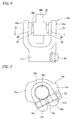
- Figs. 1 to 6 show an example of a yoke for a cross shaft universal joint according to a first embodiment of the invention.
- the yoke 10a of this embodiment is characterized in that the circumferential phases of the arrangement direction of a pair of connecting arm parts 12a, 12 and the arrangement direction of a pair of first and second flange parts 14a, 15a are shifted from each other (arranged not in parallel to each other).
- the structures and operations of the remaining parts thereof are similar to those of the above-mentioned conventional structure of Figs. 9 to 14 . Therefore, the equivalent parts are given the same designations and thus the duplicated description thereof is omitted or simplified. And, description is given below mainly of parts not described above and the characteristic parts of this embodiment.
- the yoke 10a of this embodiment is a so called press yoke to be formed by enforcing punching and bending operations sequentially on a metal plate such as a steel member using a press, and includes a base part 11a and a pair of connecting arm parts 12a, 12a.
- the base part 11a has a partially lacking cylindrical shape which includes: a discontinuous part 13a penetrating in the axial direction therethrough in one circumferential location thereof; and the first and second flange parts 14a and 15a in the two locations of the base part sandwiching the discontinuous part 13a from the two circumferential sides. Since the metal plate is folded back, the first and second flange parts 14a and 15a each have a double thickness of a metal plate and respectively include, in the mutually matching locations thereof, a through hole 17a and a screw hole 18a formed concentrically with each other. Also, in this embodiment, the axes of the through hole 17a and screw hole 18a are coincident with the thickness direction of the first and second flange parts 14a and 15a.
- the connecting arm parts 12a, 12a extend in the axial direction of the base part 11a from such two locations of the one axial end edge (in Figs. 1 and 4 , upper end edge) of the base part 11a as exist on the mutually opposite sides in the diameter direction of the base part 11a.
- the connecting arm parts 12a, 12a include in the tip portions thereof two concentric circular holes 19a and 19a.
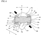
- the circumferential phases of the arrangement direction ⁇ the X direction (right and left direction) of Figs. 1, 2 and 6 , and the same direction as the axial direction X1 of the axes of the first, second circular holes 19a, 19a ⁇ of the connecting arm parts 12a, 12a and the arrangement direction ⁇ the Y direction of Figs. 2 , 6 and the same direction as the expansion direction of the discontinuous part 13a and the axial direction Y1 of the axes of the through hole 17a and screw hole 18a ⁇ of the first and second flange parts 14a, 15a are shifted from each other.
- the arrangement direction of the connecting arm parts 12a, 12a and the arrangement direction of the first, second flange parts 14a, 15a are arranged not in parallel to each other (and at a non-right angle). Specifically, the arrangement direction of the first, second flange parts 14a, 15a is set shifted (inclined), for example, 10 to 60° (in the illustrated example, 30°) from the arrangement direction of the connecting arm parts 12a, 12a.
- the shift amount (inclination angle) between the two arrangement directions can be determined properly according to the shape of the yoke 10a (particularly, the rigidity size of the connecting arm parts 12a, 12a) and the size of a radial clearance between a cup bearing 29 and the end of a shaft part 28a (which are described later).
- the circumferential phases of the axial direction X1 of the axes of the pair of circular holes 19a, 19a and the axial direction Y1 of the axes of the through hole 17a and screw hole 18a are shifted from each other.
- the axial direction Y1 of the axes of the through hole 17a and screw hole 18a is set shifted (inclined), for example, 10 to 60° (in the illustrated example, 30°) from the axial direction X1 of the axes of the pair of circular holes 19a, 19a.
- the axial direction X1 of the axes of the pair of circular holes 19a, 19a and the extension direction S of the discontinuous part 13a cross each other at a non-right angle.
- the above-structured yoke 10a of this embodiment is made of a flat material plate 22a which, for example, includes a base plate part 20a and a pair of tongue-like parts 21a, 21 a.
- the tongue-like parts 21a, 21a are disposed shifted toward the length-direction one side (in Figs. 3A to 3E , the right side) from the length-direction center of the base plate part 20a.
- Such material plate 22a can be obtained, similarly to the material plate 22 formed according to the conventional manufacturing method shown previously in Fig. 11A , by punching a metal plate between a punching die and a receiving die.
- the two ends of the base plate part 20a of this material plate 22a are folded back 180° respectively, thereby providing a first intermediate material 23a as shown in Fig. 3B .
- a first intermediate material 23a in the state of the material plate 22a, such portions of the base plate part 20a as project toward both sides from the tongue-like parts 21a, 21a are different in length dimension from each other, but the fold-back amounts of the two ends of the base plate part 20a are set equal to each other.
- the first intermediate material 23a is pressed between a pair of pressing dies and is plastically deformed, thereby providing a second intermediate material 24a as shown in Fig. 3C .
- the tongue-like parts 21a, 21a thereof to provide the pair of connecting arm parts 12a, 12a are curved in a partially cylindrical manner; and the base end near portions of the tongue-like parts 21a, 21a are bent substantially in a crank shape and the intermediate portion near portions of the tongue-like parts 21a, 21a to the leading end near portions thereof are offset with respect to the base plate part 20a.
- the central portion of the base plate part 20a is slightly curved, thereby providing a third intermediate material 25a as shown in Fig. 3D .
- the base plate part 20a of the third intermediate material 25a is curved further, thereby providing a fourth intermediate material 26a as shown in Fig. 3E .
- the cup bearings 29, 29 respectively correspond to shell type needle bearings, and include bottomed cylindrical cups 30, 30 corresponding to shell type outer rings and multiple needles 31, 31.
- the cup 30 is formed by bending a hard metal plate such as a carbon steel plate or a case hardened steel plate using plastic working such as deep drawing, and includes a cylindrical part 33, a bottom part 34 and an inward flange part 35.
- the bottom part 34 covers the whole of the axial-direction one end side (in a state where the cup bearing is assembled into the circular hole 19a, the outer surface side of the connecting arm part 12a) of the cylindrical part 33.
- the inward flange part 35 is arranged to be folded radially inward from the axial-direction other end side (in a state where the cup bearing is assembled into the circular hole 19a, the inner surface side of the connecting arm part 12a) of the cylindrical part 33.
- the above-structured cups 30, 30 are pressure inserted into the circular holes 19a, 19a and, of the outer surfaces of the connecting arm parts 12a, 12a, the opening edges of the circular holes 19a, 19a are plastically deformed radially inward to form caulking parts (not shown), thereby preventing the cups 30, 30 from moving outwardly of the circular holes 19a, 19a.
- the two ends of the shaft part 28a constituting the cross shaft 27 are respectively inserted into the radial insides of the needles 31, 31.
- the two ends of the shaft part 28a are rotatably supported with respect to the yoke 10a.
- the ends of the shaft part 28a can be inserted into the radial insides of the needles 31, 31 while having a certain degree of clearance in a stage where the two ends of the shaft part 28a are inserted into the radial insides of the needles 31, 31 (in a state before the bolt 32 is fastened), similarly to the conventional structure. This prevents the assembling workability of the cup bearing 29, 29 from being lowered.
- the end of the rotation shaft is inserted into the inside of the center hole (serration hole) of the base part 11a in the free state of the yoke 10a.
- the female serration 16a formed in the inner peripheral surface of the base part 11a and a male serration formed in the outer peripheral surface of the end of the rotation shaft are serration engaged with each other.
- a bolt (a circular washer equipped bolt) 32 is inserted through the through hole 17a and is threadedly engaged with the screw hole 18a, and is fastened further.
- the base part 11a is elastically reduced in diameter.
- the surface pressure of the serration engaged part increases, whereby the base part 11a is connected and fixed to the end of the rotation shaft in a torque transmittable manner.
- a structure capable of suppressing occurrence of shaking motion between the cup bearings 29, 29 assembled into the circular holes 19a, 19a and the end of the shaft part 28a of the cross shaft 27 rotatably supported by the cup bearings 29, 29 can be realized at low costs.
- the radial-direction inner surface of the needle 31 situated on the upper side of Fig. 6 of the needles 31, 31 constituting the cup bearing 29 arranged on the left side of Fig. 6 is pressed downward from above against the outer peripheral surface of the left-side end of Fig. 6 of the two ends of the shaft part 28a; and the radial-direction inner surface of the needle 31 situated on the lower side of Fig. 6 of the needles 31, 31 constituting the cup bearing 29 arranged on the right side of Fig. 6 is pressed upward from below against the outer peripheral surface of the right-side end of Fig. 6 of the two ends of the shaft part 28a.
- this embodiment eliminates the need for such exclusive working to suppress occurrence of shaking motion as is found in the inventions disclosed in the above-cited patent documents 2 and 3, thereby enabling suppression of the working cost of the yoke 10 of this embodiment and thus a cross shaft universal joint including the yoke 10a of this embodiment, that is, enabling cost reduction.
- the axial direction X1 of the axes of the pair of circular holes 19a, 19a is set coincident with the arrangement direction of the pair of connecting arm parts 12a, 12a
- the axial direction Y1 of the axes of the through hole 17a and screw hole 18a is set coincident with the arrangement direction Y of the first, second flange parts 14a, 15a
- the circumferential phases of the axial direction X1 of the axes of the pair of circular holes 19a, 19a and the axial direction Y1 of the axes of the through hole 17a and screw hole 18a are shifted from each other.
- the pair of circular holes 19a, 19a and the through hole 17a, screw hole 18a can be formed in the circumferential-phase intermediate positions of the pair of connecting arm parts 12a, 12a and the first, second flange parts 14a, 15a, whereby, while providing the above effects, the strengths of the pair of connecting arm parts 12a, 12a and the first, second flange parts 14a, 15a can be maintained in good balance.
- the yoke 10a for a cross shaft universal joint of the embodiment having the above structure since the pair of tongue-like parts 21a, 21a providing the pair of connecting arm parts 12a, 12a are arranged in such positions of the base plate part 20a as are shifted toward the length-direction one side thereof from the length-direction center thereof when forming the flat material plate 22a, the yoke 10a after completed is formed such that the circumferential phases of the arrangement direction of the connecting arm parts 12a, 12a and the arrangement direction of the first, second flange parts 14a, 15a are shifted from each other.
- the invention is not limited to the above embodiment but can be changed or improved properly.
- the invention is not limited to the above embodiment in which one of the mounting holes respectively formed in the pair of flange parts is formed as the through hole and the other as the screw hole.
- the pair of mounting holes are respectively constituted of through holes and a nut is pressure inserted into and fixed to one of them.
- the thickness dimension of the flange part is not limited to a double thickness dimension of a metal plate used as a material plate.
- the bearing to be incorporated into the circular hole formed in the leading end of the connecting arm part is not limited to the cup bearing (shell type needle bearing) but there may be employed various bearings such as a sliding bearing having a shape omitting a needle from the cup bearing.
- a method for manufacturing a yoke for a universal joint according to the invention is not limited to the method described in the embodiment. That is, another step(s) can be added thereto, or any one or more of the above-mentioned steps can be omitted therefrom. Or, other various methods can also be employed.
- the invention is not limited to the press yoke but can also apply to a forged yoke.
Landscapes
- Engineering & Computer Science (AREA)
- General Engineering & Computer Science (AREA)
- Mechanical Engineering (AREA)
- Forging (AREA)
- Vehicle Body Suspensions (AREA)
- Steering Controls (AREA)
Applications Claiming Priority (2)
| Application Number | Priority Date | Filing Date | Title |
|---|---|---|---|
| JP2014099166 | 2014-05-13 | ||
| PCT/JP2015/063694 WO2015174432A1 (ja) | 2014-05-13 | 2015-05-12 | 十字軸式自在継手用ヨーク及びその製造方法 |
Publications (2)
| Publication Number | Publication Date |
|---|---|
| EP3144552A1 true EP3144552A1 (de) | 2017-03-22 |
| EP3144552A4 EP3144552A4 (de) | 2018-01-24 |
Family
ID=54479969
Family Applications (1)
| Application Number | Title | Priority Date | Filing Date |
|---|---|---|---|
| EP15793199.9A Withdrawn EP3144552A4 (de) | 2014-05-13 | 2015-05-12 | Zapfenkreuzgelenkgabel mit und herstellungsverfahren dafür |
Country Status (5)
| Country | Link |
|---|---|
| US (1) | US10156267B2 (de) |
| EP (1) | EP3144552A4 (de) |
| JP (1) | JP6341276B2 (de) |
| CN (1) | CN106233014B (de) |
| WO (1) | WO2015174432A1 (de) |
Families Citing this family (5)
| Publication number | Priority date | Publication date | Assignee | Title |
|---|---|---|---|---|
| WO2015174433A1 (ja) * | 2014-05-15 | 2015-11-19 | 日本精工株式会社 | 十字軸式自在継手用ヨーク |
| WO2017130938A1 (ja) * | 2016-01-28 | 2017-08-03 | 日本精工株式会社 | 十字軸式自在継手の組立方法、及び十字軸式自在継手 |
| CN108942122B (zh) * | 2018-09-28 | 2021-01-08 | 萍乡焱鑫支承环有限公司 | 一种免校正十字轴加工方法及中心孔修正加工装置 |
| CN115890168B (zh) * | 2023-01-05 | 2023-06-09 | 浙江钱富万向节有限公司 | 一种十字轴复合加工系统及加工工艺 |
| CN117340547B (zh) * | 2023-09-28 | 2025-12-02 | 中国船舶集团渤海造船有限公司 | 一种法兰密封线加工装置及方法 |
Family Cites Families (14)
| Publication number | Priority date | Publication date | Assignee | Title |
|---|---|---|---|---|
| JPH0788859B2 (ja) * | 1988-07-25 | 1995-09-27 | 日本精工株式会社 | 自在継手および自在継手用フォークの製造方法 |
| JP2534772B2 (ja) | 1989-07-07 | 1996-09-18 | 日本精工株式会社 | 自在継手のヨ−クの製造方法 |
| JP2000320564A (ja) | 1999-05-10 | 2000-11-24 | Nsk Ltd | 自在継手のヨークとその製造方法 |
| JP2003028188A (ja) | 2001-07-19 | 2003-01-29 | Nsk Ltd | 自在継手 |
| FR2858289B1 (fr) | 2003-07-29 | 2005-10-21 | Peugeot Citroen Automobiles Sa | Ensemble de commande de direction d'un vehicule automobile |
| JP2005048803A (ja) | 2003-07-30 | 2005-02-24 | Koyo Seiko Co Ltd | 自在継手のヨーク |
| FR2863674B1 (fr) * | 2003-12-16 | 2007-04-06 | Nacam France Sas | Machoire de cardan demontable d'une colonne de direction de vehicule automobile |
| DE102005001082A1 (de) * | 2004-12-13 | 2006-06-14 | Rempel Stanztechnik Gmbh & Co.Kg | Verfahren zur Herstellung eines Gelenkkörpers und ein nach dem Verfahren hergestellter Gelenkkörper |
| JP2007327590A (ja) | 2006-06-08 | 2007-12-20 | Jtekt Corp | 十字軸継手及びこれを用いた車両用操舵装置 |
| JP2009008174A (ja) | 2007-06-28 | 2009-01-15 | Ntn Corp | ステアリングシャフトとヨークの結合構造 |
| JP2012037043A (ja) | 2010-04-01 | 2012-02-23 | Nsk Ltd | 十字軸式自在継手用ヨーク及びその製造方法 |
| JP6016005B2 (ja) * | 2012-02-08 | 2016-10-26 | 株式会社ジェイテクト | 自在継手およびヨーク |
| JP2013177949A (ja) | 2012-02-29 | 2013-09-09 | Nsk Ltd | 十字軸式自在継手及び自在継手用ヨークの製造方法 |
| US20140020487A1 (en) * | 2012-07-19 | 2014-01-23 | ZF Steering Systems, LLC | Axially located bolt guide cap |
-
2015
- 2015-05-12 WO PCT/JP2015/063694 patent/WO2015174432A1/ja not_active Ceased
- 2015-05-12 US US15/307,579 patent/US10156267B2/en active Active
- 2015-05-12 CN CN201580021697.3A patent/CN106233014B/zh active Active
- 2015-05-12 JP JP2016519277A patent/JP6341276B2/ja active Active
- 2015-05-12 EP EP15793199.9A patent/EP3144552A4/de not_active Withdrawn
Also Published As
| Publication number | Publication date |
|---|---|
| WO2015174432A1 (ja) | 2015-11-19 |
| CN106233014A (zh) | 2016-12-14 |
| EP3144552A4 (de) | 2018-01-24 |
| CN106233014B (zh) | 2019-08-23 |
| US20170058962A1 (en) | 2017-03-02 |
| US10156267B2 (en) | 2018-12-18 |
| JPWO2015174432A1 (ja) | 2017-04-20 |
| JP6341276B2 (ja) | 2018-06-13 |
Similar Documents
| Publication | Publication Date | Title |
|---|---|---|
| US10156267B2 (en) | Yoke for cross shaft universal joint and method for manufacturing the same | |
| CA3026583C (en) | Joint arrangement, prefabricated assembly, and method for producing a prefabricated assembly of a joint arrangement | |
| JP5092913B2 (ja) | 自在継手用ヨーク及び自在継手 | |
| CN109477527B (zh) | 伸缩轴 | |
| JP2007040420A (ja) | 駆動軸の製造方法 | |
| US10119575B2 (en) | Yoke for cross shaft universal joint | |
| JP6631642B2 (ja) | 十字軸式自在継手の組立方法、及び十字軸式自在継手 | |
| JP5958203B2 (ja) | ステアリング装置の製造方法 | |
| JP2013177949A (ja) | 十字軸式自在継手及び自在継手用ヨークの製造方法 | |
| JP5958202B2 (ja) | ステアリング装置の製造方法 | |
| DE102013006907B4 (de) | Herstellungsverfahren für einen Verstellmechanismus eines Fahrzeugsitzes | |
| JP5834928B2 (ja) | 十字軸式自在継手用ヨーク | |
| JP5742982B2 (ja) | シャフトと自在継手のヨークとの結合部及びその製造方法 | |
| JP6521065B2 (ja) | 自在継手用ヨーク | |
| JP5488546B2 (ja) | シャフトと自在継手のヨークとの結合部及びその製造方法 | |
| JP5958204B2 (ja) | ステアリング装置の製造方法 | |
| JP2012193863A (ja) | 自在継手用ヨーク | |
| JP2014062568A (ja) | 自在継手用ヨークの製造方法 | |
| JP2011220420A (ja) | 自在継手用ヨーク | |
| JP2012037043A (ja) | 十字軸式自在継手用ヨーク及びその製造方法 | |
| JP2003113853A (ja) | 弾性自在継手 | |
| JP2006300085A (ja) | シャフトとヨークとの結合部 | |
| JP2019056384A (ja) | 自在継手用ヨーク |
Legal Events
| Date | Code | Title | Description |
|---|---|---|---|
| PUAI | Public reference made under article 153(3) epc to a published international application that has entered the european phase |
Free format text: ORIGINAL CODE: 0009012 |
|
| 17P | Request for examination filed |
Effective date: 20161103 |
|
| AK | Designated contracting states |
Kind code of ref document: A1 Designated state(s): AL AT BE BG CH CY CZ DE DK EE ES FI FR GB GR HR HU IE IS IT LI LT LU LV MC MK MT NL NO PL PT RO RS SE SI SK SM TR |
|
| AX | Request for extension of the european patent |
Extension state: BA ME |
|
| DAV | Request for validation of the european patent (deleted) | ||
| DAX | Request for extension of the european patent (deleted) | ||
| A4 | Supplementary search report drawn up and despatched |
Effective date: 20180104 |
|
| RIC1 | Information provided on ipc code assigned before grant |
Ipc: F16D 1/08 20060101ALI20171221BHEP Ipc: F16D 3/26 20060101AFI20171221BHEP |
|
| 17Q | First examination report despatched |
Effective date: 20200210 |
|
| STAA | Information on the status of an ep patent application or granted ep patent |
Free format text: STATUS: THE APPLICATION HAS BEEN WITHDRAWN |
|
| 18W | Application withdrawn |
Effective date: 20200423 |