EP3144576B1 - Mechanismus für automatische schmierung für holzspalter - Google Patents
Mechanismus für automatische schmierung für holzspalter Download PDFInfo
- Publication number
- EP3144576B1 EP3144576B1 EP16174741.5A EP16174741A EP3144576B1 EP 3144576 B1 EP3144576 B1 EP 3144576B1 EP 16174741 A EP16174741 A EP 16174741A EP 3144576 B1 EP3144576 B1 EP 3144576B1
- Authority
- EP
- European Patent Office
- Prior art keywords
- guides
- valve
- lubrication
- lever
- log splitter
- Prior art date
- Legal status (The legal status is an assumption and is not a legal conclusion. Google has not performed a legal analysis and makes no representation as to the accuracy of the status listed.)
- Active
Links
Images

Classifications
-
- F—MECHANICAL ENGINEERING; LIGHTING; HEATING; WEAPONS; BLASTING
- F16—ENGINEERING ELEMENTS AND UNITS; GENERAL MEASURES FOR PRODUCING AND MAINTAINING EFFECTIVE FUNCTIONING OF MACHINES OR INSTALLATIONS; THERMAL INSULATION IN GENERAL
- F16N—LUBRICATING
- F16N29/00—Special means in lubricating arrangements or systems providing for the indication or detection of undesired conditions; Use of devices responsive to conditions in lubricating arrangements or systems
- F16N29/02—Special means in lubricating arrangements or systems providing for the indication or detection of undesired conditions; Use of devices responsive to conditions in lubricating arrangements or systems for influencing the supply of lubricant
-
- B—PERFORMING OPERATIONS; TRANSPORTING
- B27—WORKING OR PRESERVING WOOD OR SIMILAR MATERIAL; NAILING OR STAPLING MACHINES IN GENERAL
- B27L—REMOVING BARK OR VESTIGES OF BRANCHES; SPLITTING WOOD; MANUFACTURE OF VENEER, WOODEN STICKS, WOOD SHAVINGS, WOOD FIBRES OR WOOD POWDER
- B27L7/00—Arrangements for splitting wood
Definitions
- the present invention belongs to the field of manufacturing processes, more precisely to the field of log splitters for cutting logs into smaller pieces.
- the technical problem which is solved by the present invention, is construction of a mechanism for a log splitter that will enable automatic opening and closing of a valve with oil depending on the position of the pushing piston in a log splitter.
- Document US4262714 discloses a log splitting attachment for tractor three point hitch members.
- the device includes a top hitch connector member that is releasably mountable to the single tractor top hitch member.
- a cross connector member is adapted to mount between the two tractor bottom hitch members.
- a splitting blade is mounted on one of the connector members and a log support surface is located on the remaining member.
- a guide mechanism is also provided for movably joining the two connector members for guiding relative movement of the wood support surface in a line toward and away from the cutting blade. Actuation of a conventional rocker shaft on the tractor to cause upward movement of the bottom hitch member will cause corresponding movement of the cross member toward the top connector member, thereby causing the wood support and the blade to move toward one another. Wood held on the support surface is brought against the blade and is split as the support and blade move toward one another.
- Document CN204149284 discloses a full-automatic firewood splitting machine.
- the machine comprises a girder machine body, a draw bar assembly, a vertical knife small oil cylinder, a firewood support platform, a main oil cylinder, an auxiliary knife, a firewood loader, a fuel engine, a secondary pump, a three-piece valve and wheels, wherein the girder machine body is connected and fixed above a fuel tank through connecting pieces; the draw bar assembly, the vertical knife small oil cylinder and the firewood support platform are connected and fixed at the bottom of the back end of the girder machine body through hanging pieces; the main oil cylinder is hinged to the front end of the girder machine body through a connecting shaft; the auxiliary knife is connected with the main knife in a sleeve manner and connected with a piston rod of the vertical knife small oil cylinder; the main knife is welded at the back end of the girder machine body, and the firewood loader is connected onto the girder machine body through a hinge; the fuel
- the essence of the mechanism for automatic lubrication of guides in a log splitter is in that switching lubrication on or off depends on the position of the piston of a hydraulic cylinder with an inclined plate and a lever with a wheel, which switches an oil valve from the closed state to the open state.
- a reservoir for lubrication oil and with a lever controlled valve are installed on a pushing head, wherein the valve turns on, when the pushing head starts to move from its starting position, and wherein the valve turns off, when the pushing head returns to its starting position.
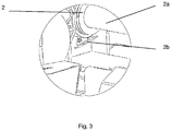
- the lever has a freely rotating wheel, which in the starting position of the pushing head anchors an inclined plate on the lower side of the hydraulic cylinder and holds the valve in the closed position.
- the piston rod together with the pushing head moves away from the inclined plate under the hydraulic cylinder and the lever lifts due to a pre-tensioned spring, which consequently results in opening of the valve with oil, which then freely runs from the reservoir to two lubrication nozzles and oil drips to the surface of the guides.
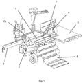
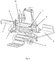
- the horizontal log splitter has a pushing head 1, which is pushed by a hydraulic cylinder 2 along the longitudinal axis of guides 3 towards a blade 4.
- a log which is usually 1 meter long, rolls along a feeder and stops on the guides 3.
- a piston rod 2a starts to move together with the pushing head 1 towards a blade 4, which cuts the log to a specified number of pieces, which is the same as the number of knives on the blade 4.
- the number of knives may be 4, 6 or more.
- the piston rod 2a returns to its starting position. Pieces of the log stay on a stowage table 6 or roll to a movable conveyor belt.
- the log splitter is controlled from a control board and includes an electro-hydraulic drive.
- the pushing head 1 is installed to the guides 3 via a horizontal base 11, which is held from the bottom side by parts 11a and 11b.
- the guides 3 are designed as a T-shaped profile, so that the pushing head 1 can reliably and safely move along the guides 3.
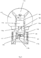
- Lateral sides 112 and 113 are weld perpendicularly to the base 11, the sides also being weld to a circularly shaped pushing plate 114.
- Bushes 112a and 113a are welded on sides 112 and 113 in parallel with the base 11.
- the base 11 has openings in the place of lubrication nozzles, so that oil can run on the guides 3.
- Bushes 112a and 113a are welded with an accessory 115a, which is on the other side welded on the plate 114.
- An oil reservoir 115 is mounted on the accessory 115a between the sides 112 and 113 and the pushing plate 114 as shown in figures 4 and 5 .
- the piston rod 2a of the hydraulic cylinder 2 is mounted in the bushes 112a and 113a.
- An inlet tube 119 is connected to the valve 117, wherein the tube is attached to the entrance of a T-shaped piece 118.
- To the output of the T-shaped piece 118 two tubes 120 are connected, which are together with nozzles 121 attached into a hole on the left and on the right side of the upper plate of the base 11.
- the mechanism for automatic lubrication of guides in a log splitter functions in such way that when lubrication is switched on, the piston rod 2a together with the pushing head 1 moves along the guides 3 and moves away from the inclined plate 2b on the hydraulic cylinder 2 and consequently the wheel 117b of the lever 117a slides on the plate 2b, sets in a new position and opens the valve 117 so that oil runs from the lubrication nozzles onto the guides 3.
- the lever 117a remains in this position until the wheel 177b of the lever 117a reaches the plate 2b, slides on it and remains in that position, which results in closing of the valve 117.
- the mechanism for automatic lubrication of the guides in a log splitter may also be executed with a lever 117a, which has a pre-tensioned spring.
- the lever 117a may be equipped with a freely-rotating wheel 117b or may be without the wheel 117b.
- the mechanism for automatic lubrication of the guides in a log splitter has an outlet tube attached to a valve 117, the tube being connected to the entrance of a distribution piece with three or more outlets, wherein the number of nozzles along the transverse side of the upper plate of the base 11 is the same as the number of outlets of the distribution piece.
- the mechanism may also be executed so that the outlet tube from the valve 117 is directly connected to the nozzle on the upper plate of the base 11.
- the mechanism for automatic lubrication of the guides in a log splitter according to embodiment I is installed into vertical splitters, wherein the geometric placement of individual functional elements on the hydraulic cylinder and the valve with the lever has to be adapted.
- the mechanism for automatic lubrication of the guides in a log splitter enables mechanical opening and closing of the valve or lubrication nozzles, respectively, reliable operation, systematic lubrication of guides, decreased wear of guides, longer life span and lower maintenance costs.
- lubrication is disabled so that oil does not drip from the log splitter to the ground.
Landscapes
- Engineering & Computer Science (AREA)
- General Engineering & Computer Science (AREA)
- Life Sciences & Earth Sciences (AREA)
- Mechanical Engineering (AREA)
- Wood Science & Technology (AREA)
- Forests & Forestry (AREA)
- General Details Of Gearings (AREA)
- Valve-Gear Or Valve Arrangements (AREA)
- Sampling And Sample Adjustment (AREA)
- Debarking, Splitting, And Disintegration Of Timber (AREA)
Claims (9)
- Holzspalter mit einem Mechanismus zur automatischen Schmierung der Führungen, wobei der Holzspalter einen elektro-hydraulischen Antrieb, einen Schubkopf (1), einen Hydraulikzylinder (2), Führungen (3), eine Schaufel (4), einen Beschicker (5), einen Stautisch (6) und eine Steuerplatine (7) umfasst, dadurch gekennzeichnet, dass die Ein- oder Ausschaltung der Schmierung von der Position eines Kolbens des Hydraulikzylinders (2) mit einer Schrägscheibe (2b) und einem Hebel (117a) mit einem Rad (117b), das ein Ölventil (117) vom geschlossenen in den geöffneten Zustand schaltet, abhängt.
- Holzspalter mit einem Mechanismus zur automatischen Schmierung von Führungen nach Anspruch 1, dadurch gekennzeichnet, dass ein Reservoir (115) für Schmieröl und ein durch einen Hebel (117a) gesteuertes Ventil (117) auf dem Schubkopf (1) montiert sind, wobei das Ventil einschaltet, wenn sich der Schubkopf aus seiner Ausgangsstellung zu bewegen beginnt, und wobei das Ventil ausschaltet, wenn der Schubkopf in seine Ausgangsstellung zurückkehrt; dass der Hebel in der Ausgangsstellung des Schubkopfes eine Schrägscheibe (2b) an der Unterseite des Hydraulikzylinders (2) verankert und das Ventil in der Schließstellung hält; dass sich, während der Benutzung des Holzspalters die Kolbenstange (2a) zusammen mit dem Schubkopf unter dem Hydraulikzylinder von der Schrägscheibe weg bewegt und der Hebel abhebt, was zur Öffnung des Ölventils führt, und das Öl dann aus dem Reservoir zu zwei Schmierdüsen fließt und die Oberfläche der Führungen betropft.
- Holzspalter mit einem Mechanismus zur automatischen Schmierung von Führungen nach Anspruch 2, dadurch gekennzeichnet, dass der Schubkopf (1) über einen horizontalen Boden (11), der von der Unterseite durch die Teile (11a) und (11b) gehalten wird, an den Führungen (3) angebracht ist; dass die Führungen (3) wie ein T-Profil ausgebildet sind; dass die Flankenseiten (112) und (113) senkrecht zum Boden (11) verschweißt sind, wobei die Seiten auch mit einer kreisförmig ausgebildeten Schubplatte (114) verschweißt sind; Buchsen (112a und 113a) werden an den Seiten (112 und 113) parallel zum Boden (11) angeschweißt; der Boden (11) weist Öffnungen an der Stelle für die Schmierdüsen (121) auf, so dass Öl auf die Führungen (3) fließen kann; die Buchsen (112a und 113a) sind mit einem Zubehörteil (115a) verschweißt, das auf der anderen Seite an der Platte (114) angeschweißt ist; zwischen den Seiten (112 und 113) und der Schubplatte (114) ist ein Ölreservoir (115) an dem Zubehörteil (115a) angebracht; die Kolbenstange (2a) des Hydraulikzylinders (2) ist in den Buchsen (112a und 113a) gelagert; unter dem Zubehör (115a) und den Buchsen (112a und 113a) erstreckt sich ein Einlassrohr (116) und ein Ventil (117) mit einem Hebel (117a) und einem Rad (117b) aus dem Reservoir (115); ein Einlassrohr (119) ist am Ventil (17) angeschlossen, wobei das Rohr am Eingang eines T-Stücks (118) befestigt ist; am Ausgang des T-Stücks (118) sind zwei Rohre (120) angeschlossen, die mit Düsen (121) zusammenwirken, die auf der linken und auf der rechten Seite der oberen Platte des Bodens (11) angeordnet sind.
- Holzspalter mit einem Mechanismus zur automatischen Schmierung von Führungen nach einem der vorhergehenden Ansprüche, dadurch gekennzeichnet, dass der Hebel (117a) eine vorgespannte Feder aufweist.
- Holzspalter mit einem Mechanismus zur automatischen Schmierung von Führungen nach einem der vorhergehenden Ansprüche, dadurch gekennzeichnet, dass in dem Hebel (117a) ein frei drehbares Rad (177b) eingebaut ist.
- Holzspalter mit einem Mechanismus zur automatischen Schmierung von Führungen nach einem der vorhergehenden Ansprüche, dadurch gekennzeichnet, dass sich bei eingeschaltetem Betrieb, die Kolbenstange (2a) zusammen mit dem Schubkopf (1) entlang der Führungen (3) bewegt und sich von einer Schrägscheibe (2b) auf dem Hydraulikzylinder (2) weg bewegt und folglich das Rad (117b) des Hebels (117a) auf der Platte (2b) gleitet, sich in eine neue Position versetzt und das Ventil (117) öffnet, so dass Öl von den Schmierdüsen auf die Führungen (3) fließt; dass der Hebel (117a) in dieser Position verbleibt bis das Rad (177b) des Hebels (117a) die Platte (2b) erreicht, auf dieser gleitet und in dieser Position verbleibt, was zum Schließen des Ventils (117) führt; dass für jede Spaltung eines Blocks die Bewegung des Schubkopfes (1) wiederholt wird, was die Schmierung der Führungen (3) ermöglicht, wenn sich der Schubkopf (1) von der Ausgangsposition in die Endposition an der Schaufel (4) bewegt und zurück in die Ausgangsposition, wenn sich die Kolbenstange (2a) in dem Zylinder (2) befindet; dass das Ein- bzw. Ausschalten der Schmierung der Führungen (3) von der Position des Schubkopfes (1), des Zylinders (2) mit der Platte (2b) und des Hebels (117a) mit dem Rad (117) abhängt.
- Holzspalter mit einem Mechanismus zur automatischen Schmierung von Führungen nach einem der vorhergehenden Ansprüche, dadurch gekennzeichnet, dass ein Auslassrohr an dem Ventil (117) befestigt ist, wobei das Rohr mit dem Eingang eines Verteilerstücks mit drei oder mehr Auslässen verbunden ist, wobei die Anzahl der Düsen entlang der Querseite der oberen Platte des Bodens (11) der Anzahl der Auslässe des Verteilerstücks entspricht.
- Holzspalter mit einem Mechanismus zur automatischen Schmierung von Führungen nach einem der vorhergehenden Ansprüche, dadurch gekennzeichnet, dass das Auslassrohr des Ventils (117) direkt an die Düse an der oberen Platte des Bodens (11) anschließt.
- Holzspalter mit einem Mechanismus zur automatischen Schmierung von Führungen nach einem der vorhergehenden Ansprüche, dadurch gekennzeichnet, dass er in Vertikalspaltern eingebaut ist, wobei die geometrische Anordnung der einzelnen Funktionselemente am Hydraulikzylinder und dem Ventil mit dem Hebel derart eingestellt wird, dass das Ein- und Ausschalten funktioniert.
Priority Applications (3)
| Application Number | Priority Date | Filing Date | Title |
|---|---|---|---|
| PL16174741T PL3144576T3 (pl) | 2015-08-21 | 2016-06-16 | Mechanizm do automatycznego smarowania prowadnic łuparki do drewna |
| SI201630510T SI3144576T1 (sl) | 2015-08-21 | 2016-06-16 | Mehanizem za avtomatsko mazanje vodila cepilnega stroja |
| HRP20192071TT HRP20192071T1 (hr) | 2015-08-21 | 2019-11-15 | Mehanizam za automatsko podmazivanje vodilica na stroju za cijepanje drva |
Applications Claiming Priority (1)
| Application Number | Priority Date | Filing Date | Title |
|---|---|---|---|
| SI201500193A SI25042A (sl) | 2015-08-21 | 2015-08-21 | Mehanizem za avtomatsko mazanje vodila cepilnega stroja |
Publications (2)
| Publication Number | Publication Date |
|---|---|
| EP3144576A1 EP3144576A1 (de) | 2017-03-22 |
| EP3144576B1 true EP3144576B1 (de) | 2019-08-21 |
Family
ID=56571109
Family Applications (1)
| Application Number | Title | Priority Date | Filing Date |
|---|---|---|---|
| EP16174741.5A Active EP3144576B1 (de) | 2015-08-21 | 2016-06-16 | Mechanismus für automatische schmierung für holzspalter |
Country Status (5)
| Country | Link |
|---|---|
| EP (1) | EP3144576B1 (de) |
| HR (1) | HRP20192071T1 (de) |
| HU (1) | HUE047384T2 (de) |
| PL (1) | PL3144576T3 (de) |
| SI (2) | SI25042A (de) |
Cited By (2)
| Publication number | Priority date | Publication date | Assignee | Title |
|---|---|---|---|---|
| DE102020126893A1 (de) | 2020-10-13 | 2022-04-14 | Oehler Maschinen Fahrzeugbau GmbH | Holzspalter |
| EP4012231A1 (de) | 2020-12-08 | 2022-06-15 | Pisek - Vitli Krpan, d.o.o. | Schmiersystem auf sprühbasis zum schmieren von antriebsketten von arbeitsmaschinen und forstwirtschaftliche winde mit dem system |
Families Citing this family (2)
| Publication number | Priority date | Publication date | Assignee | Title |
|---|---|---|---|---|
| SI25674A (sl) | 2018-07-20 | 2020-01-31 | PIŠEK - VITLI KRPAN d.o.o. | Izboljšane drsne plošče za cepilnik drv ter cepilnik drv z omenjenimi drsnimi ploščami |
| CN121269546B (zh) * | 2025-12-09 | 2026-03-13 | 四川省工业设备安装集团有限公司 | 一种大型设备吊装的桥式吊装装置 |
Family Cites Families (5)
| Publication number | Priority date | Publication date | Assignee | Title |
|---|---|---|---|---|
| US3077214A (en) * | 1959-08-27 | 1963-02-12 | Waco Aircraft Co | Log splitter |
| US4262714A (en) * | 1979-06-18 | 1981-04-21 | James L. Price | Log splitting attachment for tractor three point hitch members |
| US4366847A (en) * | 1980-12-11 | 1983-01-04 | Blecha Wayland C | Log splitter |
| IT1287641B1 (it) * | 1996-05-08 | 1998-08-06 | Bell Srl | Sistema idraulico di servizio per macchine spaccalegna |
| CN204149284U (zh) * | 2014-10-16 | 2015-02-11 | 张品杰 | 一种全自动劈柴机 |
-
2015
- 2015-08-21 SI SI201500193A patent/SI25042A/sl not_active IP Right Cessation
-
2016
- 2016-06-16 EP EP16174741.5A patent/EP3144576B1/de active Active
- 2016-06-16 SI SI201630510T patent/SI3144576T1/sl unknown
- 2016-06-16 HU HUE16174741A patent/HUE047384T2/hu unknown
- 2016-06-16 PL PL16174741T patent/PL3144576T3/pl unknown
-
2019
- 2019-11-15 HR HRP20192071TT patent/HRP20192071T1/hr unknown
Non-Patent Citations (1)
| Title |
|---|
| None * |
Cited By (2)
| Publication number | Priority date | Publication date | Assignee | Title |
|---|---|---|---|---|
| DE102020126893A1 (de) | 2020-10-13 | 2022-04-14 | Oehler Maschinen Fahrzeugbau GmbH | Holzspalter |
| EP4012231A1 (de) | 2020-12-08 | 2022-06-15 | Pisek - Vitli Krpan, d.o.o. | Schmiersystem auf sprühbasis zum schmieren von antriebsketten von arbeitsmaschinen und forstwirtschaftliche winde mit dem system |
Also Published As
| Publication number | Publication date |
|---|---|
| EP3144576A1 (de) | 2017-03-22 |
| PL3144576T3 (pl) | 2020-03-31 |
| SI3144576T1 (sl) | 2019-12-31 |
| HUE047384T2 (hu) | 2020-04-28 |
| SI25042A (sl) | 2017-02-28 |
| HRP20192071T1 (hr) | 2020-02-07 |
Similar Documents
| Publication | Publication Date | Title |
|---|---|---|
| US3779295A (en) | Log splitter and tube bender | |
| EP3144576A1 (de) | Mechanismus für automatische schmierung für holzspalter | |
| EP2641711B1 (de) | Schmiersystem und Arbeitsmaschine mit einem solchen System | |
| US20100024919A1 (en) | Log splittter | |
| US4164965A (en) | Combination log saw and splitter machine | |
| KR102646277B1 (ko) | 비교적 강성인 물질의 작업툴용 공압구동유닛과 비교적 강성인 물질을 가공하기 위한 작업기계 | |
| US2667922A (en) | Machine for cutting sheet material | |
| US4337809A (en) | Log Splitter | |
| DE1511096A1 (de) | Kartonfalzmaschine | |
| AT515182A2 (de) | Holzspalter | |
| WO2010122225A1 (en) | A method for making firewood with a wood chopping machine, and a wood chopping machine | |
| US2837156A (en) | Tube cutting die | |
| CN208914769U (zh) | 印刷机自动切料装置 | |
| GB683568A (en) | Improvements in or relating to a machine for cutting paper and like material | |
| FI125359B (fi) | Pilkekone | |
| FI111447B (fi) | Pilkekone | |
| SI24385A (sl) | Horizontalni cepilni stroj | |
| FR2529821A1 (fr) | Tronconneuse-fendeuse hydraulique pour la production de bois de chauffage a partir de pieces de bois brutes telles que perches, rondins, troncs, quartiers | |
| DE861488C (de) | Steuereinrichtung fuer eine Vorrichtung zum Abheben des Ziehmessers beim Rueckhub undZurueckfuehren desselben in die Arbeitsstellung beim Arbeitshub bei einer Nutenziehmaschine | |
| AU2008100777B4 (en) | Wood splitter | |
| KR200432161Y1 (ko) | 유압식 선재 절단장치 | |
| WO2005072924A1 (en) | Cutting and splitting device | |
| CN105710185A (zh) | 一种钢管切口机 | |
| US2651240A (en) | Machine for shaving electrotypes, stereotypes, and the like | |
| CN219191363U (zh) | 一种液压机回程缸系统 |
Legal Events
| Date | Code | Title | Description |
|---|---|---|---|
| PUAI | Public reference made under article 153(3) epc to a published international application that has entered the european phase |
Free format text: ORIGINAL CODE: 0009012 |
|
| STAA | Information on the status of an ep patent application or granted ep patent |
Free format text: STATUS: THE APPLICATION HAS BEEN PUBLISHED |
|
| AK | Designated contracting states |
Kind code of ref document: A1 Designated state(s): AL AT BE BG CH CY CZ DE DK EE ES FI FR GB GR HR HU IE IS IT LI LT LU LV MC MK MT NL NO PL PT RO RS SE SI SK SM TR |
|
| AX | Request for extension of the european patent |
Extension state: BA ME |
|
| STAA | Information on the status of an ep patent application or granted ep patent |
Free format text: STATUS: REQUEST FOR EXAMINATION WAS MADE |
|
| 17P | Request for examination filed |
Effective date: 20170504 |
|
| RBV | Designated contracting states (corrected) |
Designated state(s): AL AT BE BG CH CY CZ DE DK EE ES FI FR GB GR HR HU IE IS IT LI LT LU LV MC MK MT NL NO PL PT RO RS SE SI SK SM TR |
|
| GRAP | Despatch of communication of intention to grant a patent |
Free format text: ORIGINAL CODE: EPIDOSNIGR1 |
|
| STAA | Information on the status of an ep patent application or granted ep patent |
Free format text: STATUS: GRANT OF PATENT IS INTENDED |
|
| INTG | Intention to grant announced |
Effective date: 20190527 |
|
| GRAS | Grant fee paid |
Free format text: ORIGINAL CODE: EPIDOSNIGR3 |
|
| GRAA | (expected) grant |
Free format text: ORIGINAL CODE: 0009210 |
|
| STAA | Information on the status of an ep patent application or granted ep patent |
Free format text: STATUS: THE PATENT HAS BEEN GRANTED |
|
| AK | Designated contracting states |
Kind code of ref document: B1 Designated state(s): AL AT BE BG CH CY CZ DE DK EE ES FI FR GB GR HR HU IE IS IT LI LT LU LV MC MK MT NL NO PL PT RO RS SE SI SK SM TR |
|
| REG | Reference to a national code |
Ref country code: GB Ref legal event code: FG4D |
|
| REG | Reference to a national code |
Ref country code: CH Ref legal event code: EP |
|
| REG | Reference to a national code |
Ref country code: DE Ref legal event code: R096 Ref document number: 602016018867 Country of ref document: DE |
|
| REG | Reference to a national code |
Ref country code: AT Ref legal event code: REF Ref document number: 1170162 Country of ref document: AT Kind code of ref document: T Effective date: 20190915 |
|
| REG | Reference to a national code |
Ref country code: IE Ref legal event code: FG4D |
|
| REG | Reference to a national code |
Ref country code: CH Ref legal event code: NV Representative=s name: DR. LUSUARDI AG, CH |
|
| REG | Reference to a national code |
Ref country code: LT Ref legal event code: MG4D |
|
| REG | Reference to a national code |
Ref country code: NL Ref legal event code: MP Effective date: 20190821 |
|
| PG25 | Lapsed in a contracting state [announced via postgrant information from national office to epo] |
Ref country code: FI Free format text: LAPSE BECAUSE OF FAILURE TO SUBMIT A TRANSLATION OF THE DESCRIPTION OR TO PAY THE FEE WITHIN THE PRESCRIBED TIME-LIMIT Effective date: 20190821 Ref country code: LT Free format text: LAPSE BECAUSE OF FAILURE TO SUBMIT A TRANSLATION OF THE DESCRIPTION OR TO PAY THE FEE WITHIN THE PRESCRIBED TIME-LIMIT Effective date: 20190821 Ref country code: NL Free format text: LAPSE BECAUSE OF FAILURE TO SUBMIT A TRANSLATION OF THE DESCRIPTION OR TO PAY THE FEE WITHIN THE PRESCRIBED TIME-LIMIT Effective date: 20190821 Ref country code: PT Free format text: LAPSE BECAUSE OF FAILURE TO SUBMIT A TRANSLATION OF THE DESCRIPTION OR TO PAY THE FEE WITHIN THE PRESCRIBED TIME-LIMIT Effective date: 20191223 Ref country code: SE Free format text: LAPSE BECAUSE OF FAILURE TO SUBMIT A TRANSLATION OF THE DESCRIPTION OR TO PAY THE FEE WITHIN THE PRESCRIBED TIME-LIMIT Effective date: 20190821 Ref country code: BG Free format text: LAPSE BECAUSE OF FAILURE TO SUBMIT A TRANSLATION OF THE DESCRIPTION OR TO PAY THE FEE WITHIN THE PRESCRIBED TIME-LIMIT Effective date: 20191121 Ref country code: NO Free format text: LAPSE BECAUSE OF FAILURE TO SUBMIT A TRANSLATION OF THE DESCRIPTION OR TO PAY THE FEE WITHIN THE PRESCRIBED TIME-LIMIT Effective date: 20191121 |
|
| REG | Reference to a national code |
Ref country code: SK Ref legal event code: T3 Ref document number: E 32725 Country of ref document: SK |
|
| REG | Reference to a national code |
Ref country code: HR Ref legal event code: T1PR Ref document number: P20192071 Country of ref document: HR |
|
| PG25 | Lapsed in a contracting state [announced via postgrant information from national office to epo] |
Ref country code: IS Free format text: LAPSE BECAUSE OF FAILURE TO SUBMIT A TRANSLATION OF THE DESCRIPTION OR TO PAY THE FEE WITHIN THE PRESCRIBED TIME-LIMIT Effective date: 20191221 Ref country code: ES Free format text: LAPSE BECAUSE OF FAILURE TO SUBMIT A TRANSLATION OF THE DESCRIPTION OR TO PAY THE FEE WITHIN THE PRESCRIBED TIME-LIMIT Effective date: 20190821 Ref country code: AL Free format text: LAPSE BECAUSE OF FAILURE TO SUBMIT A TRANSLATION OF THE DESCRIPTION OR TO PAY THE FEE WITHIN THE PRESCRIBED TIME-LIMIT Effective date: 20190821 Ref country code: LV Free format text: LAPSE BECAUSE OF FAILURE TO SUBMIT A TRANSLATION OF THE DESCRIPTION OR TO PAY THE FEE WITHIN THE PRESCRIBED TIME-LIMIT Effective date: 20190821 Ref country code: GR Free format text: LAPSE BECAUSE OF FAILURE TO SUBMIT A TRANSLATION OF THE DESCRIPTION OR TO PAY THE FEE WITHIN THE PRESCRIBED TIME-LIMIT Effective date: 20191122 Ref country code: RS Free format text: LAPSE BECAUSE OF FAILURE TO SUBMIT A TRANSLATION OF THE DESCRIPTION OR TO PAY THE FEE WITHIN THE PRESCRIBED TIME-LIMIT Effective date: 20190821 |
|
| PG25 | Lapsed in a contracting state [announced via postgrant information from national office to epo] |
Ref country code: TR Free format text: LAPSE BECAUSE OF FAILURE TO SUBMIT A TRANSLATION OF THE DESCRIPTION OR TO PAY THE FEE WITHIN THE PRESCRIBED TIME-LIMIT Effective date: 20190821 |
|
| REG | Reference to a national code |
Ref country code: HU Ref legal event code: AG4A Ref document number: E047384 Country of ref document: HU |
|
| PG25 | Lapsed in a contracting state [announced via postgrant information from national office to epo] |
Ref country code: EE Free format text: LAPSE BECAUSE OF FAILURE TO SUBMIT A TRANSLATION OF THE DESCRIPTION OR TO PAY THE FEE WITHIN THE PRESCRIBED TIME-LIMIT Effective date: 20190821 Ref country code: DK Free format text: LAPSE BECAUSE OF FAILURE TO SUBMIT A TRANSLATION OF THE DESCRIPTION OR TO PAY THE FEE WITHIN THE PRESCRIBED TIME-LIMIT Effective date: 20190821 Ref country code: RO Free format text: LAPSE BECAUSE OF FAILURE TO SUBMIT A TRANSLATION OF THE DESCRIPTION OR TO PAY THE FEE WITHIN THE PRESCRIBED TIME-LIMIT Effective date: 20190821 |
|
| PG25 | Lapsed in a contracting state [announced via postgrant information from national office to epo] |
Ref country code: SM Free format text: LAPSE BECAUSE OF FAILURE TO SUBMIT A TRANSLATION OF THE DESCRIPTION OR TO PAY THE FEE WITHIN THE PRESCRIBED TIME-LIMIT Effective date: 20190821 Ref country code: IS Free format text: LAPSE BECAUSE OF FAILURE TO SUBMIT A TRANSLATION OF THE DESCRIPTION OR TO PAY THE FEE WITHIN THE PRESCRIBED TIME-LIMIT Effective date: 20200224 |
|
| REG | Reference to a national code |
Ref country code: DE Ref legal event code: R097 Ref document number: 602016018867 Country of ref document: DE |
|
| REG | Reference to a national code |
Ref country code: HR Ref legal event code: ODRP Ref document number: P20192071 Country of ref document: HR Payment date: 20200604 Year of fee payment: 5 |
|
| PLBE | No opposition filed within time limit |
Free format text: ORIGINAL CODE: 0009261 |
|
| STAA | Information on the status of an ep patent application or granted ep patent |
Free format text: STATUS: NO OPPOSITION FILED WITHIN TIME LIMIT |
|
| PG2D | Information on lapse in contracting state deleted |
Ref country code: IS |
|
| 26N | No opposition filed |
Effective date: 20200603 |
|
| REG | Reference to a national code |
Ref country code: AT Ref legal event code: UEP Ref document number: 1170162 Country of ref document: AT Kind code of ref document: T Effective date: 20190821 |
|
| PG25 | Lapsed in a contracting state [announced via postgrant information from national office to epo] |
Ref country code: MC Free format text: LAPSE BECAUSE OF FAILURE TO SUBMIT A TRANSLATION OF THE DESCRIPTION OR TO PAY THE FEE WITHIN THE PRESCRIBED TIME-LIMIT Effective date: 20190821 |
|
| GBPC | Gb: european patent ceased through non-payment of renewal fee |
Effective date: 20200616 |
|
| PG25 | Lapsed in a contracting state [announced via postgrant information from national office to epo] |
Ref country code: LU Free format text: LAPSE BECAUSE OF NON-PAYMENT OF DUE FEES Effective date: 20200616 |
|
| REG | Reference to a national code |
Ref country code: BE Ref legal event code: MM Effective date: 20200630 |
|
| PG25 | Lapsed in a contracting state [announced via postgrant information from national office to epo] |
Ref country code: IE Free format text: LAPSE BECAUSE OF NON-PAYMENT OF DUE FEES Effective date: 20200616 Ref country code: GB Free format text: LAPSE BECAUSE OF NON-PAYMENT OF DUE FEES Effective date: 20200616 |
|
| PG25 | Lapsed in a contracting state [announced via postgrant information from national office to epo] |
Ref country code: BE Free format text: LAPSE BECAUSE OF NON-PAYMENT OF DUE FEES Effective date: 20200630 |
|
| REG | Reference to a national code |
Ref country code: HR Ref legal event code: ODRP Ref document number: P20192071 Country of ref document: HR Payment date: 20210608 Year of fee payment: 6 |
|
| PG25 | Lapsed in a contracting state [announced via postgrant information from national office to epo] |
Ref country code: MT Free format text: LAPSE BECAUSE OF FAILURE TO SUBMIT A TRANSLATION OF THE DESCRIPTION OR TO PAY THE FEE WITHIN THE PRESCRIBED TIME-LIMIT Effective date: 20190821 Ref country code: CY Free format text: LAPSE BECAUSE OF FAILURE TO SUBMIT A TRANSLATION OF THE DESCRIPTION OR TO PAY THE FEE WITHIN THE PRESCRIBED TIME-LIMIT Effective date: 20190821 |
|
| PG25 | Lapsed in a contracting state [announced via postgrant information from national office to epo] |
Ref country code: MK Free format text: LAPSE BECAUSE OF FAILURE TO SUBMIT A TRANSLATION OF THE DESCRIPTION OR TO PAY THE FEE WITHIN THE PRESCRIBED TIME-LIMIT Effective date: 20190821 |
|
| REG | Reference to a national code |
Ref country code: HR Ref legal event code: ODRP Ref document number: P20192071 Country of ref document: HR Payment date: 20220615 Year of fee payment: 7 |
|
| REG | Reference to a national code |
Ref country code: HR Ref legal event code: ODRP Ref document number: P20192071 Country of ref document: HR Payment date: 20230614 Year of fee payment: 8 |
|
| P01 | Opt-out of the competence of the unified patent court (upc) registered |
Effective date: 20230521 |
|
| REG | Reference to a national code |
Ref country code: HR Ref legal event code: ODRP Ref document number: P20192071 Country of ref document: HR Payment date: 20240614 Year of fee payment: 9 |
|
| REG | Reference to a national code |
Ref country code: HR Ref legal event code: ODRP Ref document number: P20192071 Country of ref document: HR Payment date: 20250613 Year of fee payment: 10 |
|
| PGFP | Annual fee paid to national office [announced via postgrant information from national office to epo] |
Ref country code: PL Payment date: 20250612 Year of fee payment: 10 Ref country code: DE Payment date: 20250623 Year of fee payment: 10 |
|
| PGFP | Annual fee paid to national office [announced via postgrant information from national office to epo] |
Ref country code: HR Payment date: 20250613 Year of fee payment: 10 |
|
| PGFP | Annual fee paid to national office [announced via postgrant information from national office to epo] |
Ref country code: HU Payment date: 20250612 Year of fee payment: 10 Ref country code: FR Payment date: 20250627 Year of fee payment: 10 |
|
| PGFP | Annual fee paid to national office [announced via postgrant information from national office to epo] |
Ref country code: AT Payment date: 20250701 Year of fee payment: 10 |
|
| PGFP | Annual fee paid to national office [announced via postgrant information from national office to epo] |
Ref country code: SK Payment date: 20250613 Year of fee payment: 10 |
|
| PGFP | Annual fee paid to national office [announced via postgrant information from national office to epo] |
Ref country code: CZ Payment date: 20250612 Year of fee payment: 10 |
|
| PGFP | Annual fee paid to national office [announced via postgrant information from national office to epo] |
Ref country code: SI Payment date: 20250611 Year of fee payment: 10 |
|
| PGFP | Annual fee paid to national office [announced via postgrant information from national office to epo] |
Ref country code: IT Payment date: 20250626 Year of fee payment: 10 |
|
| PGFP | Annual fee paid to national office [announced via postgrant information from national office to epo] |
Ref country code: CH Payment date: 20250701 Year of fee payment: 10 |