EP3144624A1 - Échangeur de chaleur et dispositif à cycle de réfrigération pourvu dudit échangeur - Google Patents
Échangeur de chaleur et dispositif à cycle de réfrigération pourvu dudit échangeur Download PDFInfo
- Publication number
- EP3144624A1 EP3144624A1 EP14892097.8A EP14892097A EP3144624A1 EP 3144624 A1 EP3144624 A1 EP 3144624A1 EP 14892097 A EP14892097 A EP 14892097A EP 3144624 A1 EP3144624 A1 EP 3144624A1
- Authority
- EP
- European Patent Office
- Prior art keywords
- heat transfer
- transfer tubes
- heat exchanger
- heat
- region
- Prior art date
- Legal status (The legal status is an assumption and is not a legal conclusion. Google has not performed a legal analysis and makes no representation as to the accuracy of the status listed.)
- Withdrawn
Links
Images


Classifications
-
- F—MECHANICAL ENGINEERING; LIGHTING; HEATING; WEAPONS; BLASTING
- F28—HEAT EXCHANGE IN GENERAL
- F28F—DETAILS OF HEAT-EXCHANGE AND HEAT-TRANSFER APPARATUS, OF GENERAL APPLICATION
- F28F1/00—Tubular elements; Assemblies of tubular elements
- F28F1/10—Tubular elements and assemblies thereof with means for increasing heat-transfer area, e.g. with fins, with projections, with recesses
- F28F1/12—Tubular elements and assemblies thereof with means for increasing heat-transfer area, e.g. with fins, with projections, with recesses the means being only outside the tubular element
- F28F1/24—Tubular elements and assemblies thereof with means for increasing heat-transfer area, e.g. with fins, with projections, with recesses the means being only outside the tubular element and extending transversely
- F28F1/32—Tubular elements and assemblies thereof with means for increasing heat-transfer area, e.g. with fins, with projections, with recesses the means being only outside the tubular element and extending transversely the means having portions engaging further tubular elements
-
- F—MECHANICAL ENGINEERING; LIGHTING; HEATING; WEAPONS; BLASTING
- F25—REFRIGERATION OR COOLING; COMBINED HEATING AND REFRIGERATION SYSTEMS; HEAT PUMP SYSTEMS; MANUFACTURE OR STORAGE OF ICE; LIQUEFACTION SOLIDIFICATION OF GASES
- F25B—REFRIGERATION MACHINES, PLANTS OR SYSTEMS; COMBINED HEATING AND REFRIGERATION SYSTEMS; HEAT PUMP SYSTEMS
- F25B47/00—Arrangements for preventing or removing deposits or corrosion, not provided for in another subclass
- F25B47/006—Arrangements for preventing or removing deposits or corrosion, not provided for in another subclass for preventing frost
-
- F—MECHANICAL ENGINEERING; LIGHTING; HEATING; WEAPONS; BLASTING
- F24—HEATING; RANGES; VENTILATING
- F24F—AIR-CONDITIONING; AIR-HUMIDIFICATION; VENTILATION; USE OF AIR CURRENTS FOR SCREENING
- F24F1/00—Room units for air-conditioning, e.g. separate or self-contained units or units receiving primary air from a central station
- F24F1/06—Separate outdoor units, e.g. outdoor unit to be linked to a separate room comprising a compressor and a heat exchanger
- F24F1/14—Heat exchangers specially adapted for separate outdoor units
- F24F1/18—Heat exchangers specially adapted for separate outdoor units characterised by their shape
-
- F—MECHANICAL ENGINEERING; LIGHTING; HEATING; WEAPONS; BLASTING
- F25—REFRIGERATION OR COOLING; COMBINED HEATING AND REFRIGERATION SYSTEMS; HEAT PUMP SYSTEMS; MANUFACTURE OR STORAGE OF ICE; LIQUEFACTION SOLIDIFICATION OF GASES
- F25B—REFRIGERATION MACHINES, PLANTS OR SYSTEMS; COMBINED HEATING AND REFRIGERATION SYSTEMS; HEAT PUMP SYSTEMS
- F25B30/00—Heat pumps
- F25B30/02—Heat pumps of the compression type
-
- F—MECHANICAL ENGINEERING; LIGHTING; HEATING; WEAPONS; BLASTING
- F25—REFRIGERATION OR COOLING; COMBINED HEATING AND REFRIGERATION SYSTEMS; HEAT PUMP SYSTEMS; MANUFACTURE OR STORAGE OF ICE; LIQUEFACTION SOLIDIFICATION OF GASES
- F25B—REFRIGERATION MACHINES, PLANTS OR SYSTEMS; COMBINED HEATING AND REFRIGERATION SYSTEMS; HEAT PUMP SYSTEMS
- F25B39/00—Evaporators; Condensers
-
- F—MECHANICAL ENGINEERING; LIGHTING; HEATING; WEAPONS; BLASTING
- F28—HEAT EXCHANGE IN GENERAL
- F28D—HEAT-EXCHANGE APPARATUS, NOT PROVIDED FOR IN ANOTHER SUBCLASS, IN WHICH THE HEAT-EXCHANGE MEDIA DO NOT COME INTO DIRECT CONTACT
- F28D1/00—Heat-exchange apparatus having stationary conduit assemblies for one heat-exchange medium only, the media being in contact with different sides of the conduit wall, in which the other heat-exchange medium is a large body of fluid, e.g. domestic or motor car radiators
- F28D1/02—Heat-exchange apparatus having stationary conduit assemblies for one heat-exchange medium only, the media being in contact with different sides of the conduit wall, in which the other heat-exchange medium is a large body of fluid, e.g. domestic or motor car radiators with heat-exchange conduits immersed in the body of fluid
- F28D1/0233—Heat-exchange apparatus having stationary conduit assemblies for one heat-exchange medium only, the media being in contact with different sides of the conduit wall, in which the other heat-exchange medium is a large body of fluid, e.g. domestic or motor car radiators with heat-exchange conduits immersed in the body of fluid with air flow channels
- F28D1/024—Heat-exchange apparatus having stationary conduit assemblies for one heat-exchange medium only, the media being in contact with different sides of the conduit wall, in which the other heat-exchange medium is a large body of fluid, e.g. domestic or motor car radiators with heat-exchange conduits immersed in the body of fluid with air flow channels with an air driving element
-
- F—MECHANICAL ENGINEERING; LIGHTING; HEATING; WEAPONS; BLASTING
- F28—HEAT EXCHANGE IN GENERAL
- F28D—HEAT-EXCHANGE APPARATUS, NOT PROVIDED FOR IN ANOTHER SUBCLASS, IN WHICH THE HEAT-EXCHANGE MEDIA DO NOT COME INTO DIRECT CONTACT
- F28D1/00—Heat-exchange apparatus having stationary conduit assemblies for one heat-exchange medium only, the media being in contact with different sides of the conduit wall, in which the other heat-exchange medium is a large body of fluid, e.g. domestic or motor car radiators
- F28D1/02—Heat-exchange apparatus having stationary conduit assemblies for one heat-exchange medium only, the media being in contact with different sides of the conduit wall, in which the other heat-exchange medium is a large body of fluid, e.g. domestic or motor car radiators with heat-exchange conduits immersed in the body of fluid
- F28D1/04—Heat-exchange apparatus having stationary conduit assemblies for one heat-exchange medium only, the media being in contact with different sides of the conduit wall, in which the other heat-exchange medium is a large body of fluid, e.g. domestic or motor car radiators with heat-exchange conduits immersed in the body of fluid with tubular conduits
- F28D1/0408—Multi-circuit heat exchangers, e.g. integrating different heat exchange sections in the same unit or heat exchangers for more than two fluids
- F28D1/0426—Multi-circuit heat exchangers, e.g. integrating different heat exchange sections in the same unit or heat exchangers for more than two fluids with units having particular arrangement relative to the large body of fluid, e.g. with interleaved units or with adjacent heat exchange units in common air flow or with units extending at an angle to each other or with units arranged around a central element
- F28D1/0435—Combination of units extending one behind the other
-
- F—MECHANICAL ENGINEERING; LIGHTING; HEATING; WEAPONS; BLASTING
- F28—HEAT EXCHANGE IN GENERAL
- F28D—HEAT-EXCHANGE APPARATUS, NOT PROVIDED FOR IN ANOTHER SUBCLASS, IN WHICH THE HEAT-EXCHANGE MEDIA DO NOT COME INTO DIRECT CONTACT
- F28D1/00—Heat-exchange apparatus having stationary conduit assemblies for one heat-exchange medium only, the media being in contact with different sides of the conduit wall, in which the other heat-exchange medium is a large body of fluid, e.g. domestic or motor car radiators
- F28D1/02—Heat-exchange apparatus having stationary conduit assemblies for one heat-exchange medium only, the media being in contact with different sides of the conduit wall, in which the other heat-exchange medium is a large body of fluid, e.g. domestic or motor car radiators with heat-exchange conduits immersed in the body of fluid
- F28D1/04—Heat-exchange apparatus having stationary conduit assemblies for one heat-exchange medium only, the media being in contact with different sides of the conduit wall, in which the other heat-exchange medium is a large body of fluid, e.g. domestic or motor car radiators with heat-exchange conduits immersed in the body of fluid with tubular conduits
- F28D1/047—Heat-exchange apparatus having stationary conduit assemblies for one heat-exchange medium only, the media being in contact with different sides of the conduit wall, in which the other heat-exchange medium is a large body of fluid, e.g. domestic or motor car radiators with heat-exchange conduits immersed in the body of fluid with tubular conduits the conduits being bent, e.g. in a serpentine or zig-zag
- F28D1/0477—Heat-exchange apparatus having stationary conduit assemblies for one heat-exchange medium only, the media being in contact with different sides of the conduit wall, in which the other heat-exchange medium is a large body of fluid, e.g. domestic or motor car radiators with heat-exchange conduits immersed in the body of fluid with tubular conduits the conduits being bent, e.g. in a serpentine or zig-zag the conduits being bent in a serpentine or zig-zag
-
- F—MECHANICAL ENGINEERING; LIGHTING; HEATING; WEAPONS; BLASTING
- F28—HEAT EXCHANGE IN GENERAL
- F28F—DETAILS OF HEAT-EXCHANGE AND HEAT-TRANSFER APPARATUS, OF GENERAL APPLICATION
- F28F1/00—Tubular elements; Assemblies of tubular elements
- F28F1/10—Tubular elements and assemblies thereof with means for increasing heat-transfer area, e.g. with fins, with projections, with recesses
- F28F1/12—Tubular elements and assemblies thereof with means for increasing heat-transfer area, e.g. with fins, with projections, with recesses the means being only outside the tubular element
- F28F1/24—Tubular elements and assemblies thereof with means for increasing heat-transfer area, e.g. with fins, with projections, with recesses the means being only outside the tubular element and extending transversely
- F28F1/32—Tubular elements and assemblies thereof with means for increasing heat-transfer area, e.g. with fins, with projections, with recesses the means being only outside the tubular element and extending transversely the means having portions engaging further tubular elements
- F28F1/325—Fins with openings
-
- F—MECHANICAL ENGINEERING; LIGHTING; HEATING; WEAPONS; BLASTING
- F25—REFRIGERATION OR COOLING; COMBINED HEATING AND REFRIGERATION SYSTEMS; HEAT PUMP SYSTEMS; MANUFACTURE OR STORAGE OF ICE; LIQUEFACTION SOLIDIFICATION OF GASES
- F25B—REFRIGERATION MACHINES, PLANTS OR SYSTEMS; COMBINED HEATING AND REFRIGERATION SYSTEMS; HEAT PUMP SYSTEMS
- F25B13/00—Compression machines, plants or systems, with reversible cycle
-
- F—MECHANICAL ENGINEERING; LIGHTING; HEATING; WEAPONS; BLASTING
- F25—REFRIGERATION OR COOLING; COMBINED HEATING AND REFRIGERATION SYSTEMS; HEAT PUMP SYSTEMS; MANUFACTURE OR STORAGE OF ICE; LIQUEFACTION SOLIDIFICATION OF GASES
- F25B—REFRIGERATION MACHINES, PLANTS OR SYSTEMS; COMBINED HEATING AND REFRIGERATION SYSTEMS; HEAT PUMP SYSTEMS
- F25B39/00—Evaporators; Condensers
- F25B39/02—Evaporators
-
- F—MECHANICAL ENGINEERING; LIGHTING; HEATING; WEAPONS; BLASTING
- F28—HEAT EXCHANGE IN GENERAL
- F28D—HEAT-EXCHANGE APPARATUS, NOT PROVIDED FOR IN ANOTHER SUBCLASS, IN WHICH THE HEAT-EXCHANGE MEDIA DO NOT COME INTO DIRECT CONTACT
- F28D21/00—Heat-exchange apparatus not covered by any of the groups F28D1/00 - F28D20/00
- F28D2021/0019—Other heat exchangers for particular applications; Heat exchange systems not otherwise provided for
- F28D2021/0061—Other heat exchangers for particular applications; Heat exchange systems not otherwise provided for for phase-change applications
-
- F—MECHANICAL ENGINEERING; LIGHTING; HEATING; WEAPONS; BLASTING
- F28—HEAT EXCHANGE IN GENERAL
- F28F—DETAILS OF HEAT-EXCHANGE AND HEAT-TRANSFER APPARATUS, OF GENERAL APPLICATION
- F28F2250/00—Arrangements for modifying the flow of the heat exchange media, e.g. flow guiding means; Particular flow patterns
- F28F2250/08—Fluid driving means, e.g. pumps, fans
Definitions
- the present invention relates to a heat exchanger installed in a heat source unit such as an outdoor unit and configured to minimize deterioration of frost formation resistance, and a refrigeration cycle apparatus including the heat exchanger.
- a plate fin-tube heat exchanger has been conventional as a heat exchanger applied to a refrigeration cycle apparatus, such as an air-conditioning apparatus.
- a heat exchanger is generally formed of a plurality of plate-shaped fins having circular holes and a plurality of heat transfer tubes having circular cross sections inserted through the fins.
- a fin-tube heat exchanger including a plurality of heat transfer fins stacked substantially parallel to each other with predetermined gaps and a plurality of heat transfer tubes extending through the heat transfer fins in a direction substantially perpendicular to a planar direction of the heat transfer fins, the heat transfer tubes extending through through-holes in the heat transfer fins, substantially cylindrical fin collars being formed around the through-holes and extending in the direction substantially perpendicular to the planar direction of the heat transfer fins, and the heat transfer tubes being inserted through the through-holes while the heat transfer tubes being in close contact with the fin collars to exchange heat between gas flowing in the planar direction of the heat transfer fins and heat refrigerant flowing inside the heat transfer tubes, wherein slits are provided in the heat transfer fins only in a direction of rows substantially perpendicular to a flow direction of the gas, and wherein parts of the heat transfer fins upwind of the slits in flow of the gas are uplifted to
- Patent Literature 2 for example.
- the fin-tube heat exchanger described in Patent Literature 1 is capable of obtaining excellent heat transfer performance by forming the projections, and secures drain passages for the condensed water and minimizes an increase in ventilation resistance by defining the areas in which the projections are not formed.
- the heat exchangers described in Patent Literatures 2 and 3 improve the performance of the heat exchangers by enhancing heat transfer with cutouts, such as slits, provided between the heat transfer tubes, and are provided with devices, such as drain passages provided between the heat transfer tubes, to improve the drainage performance.
- the heat exchanger When a heating operation is performed with any of the thus-configured heat exchangers installed in a heat source unit such as an outdoor unit, the heat exchanger operates as an evaporator. Operating a heat exchanger as an evaporator may form frost on the heat exchanger.
- the frost formation on the heat exchanger occurs on leading edge portions of the fins (most upstream sides of the fins in flow of air) and fin slit portions, and also on parts of the heat transfer tubes. Further, the frost formation on the parts of the heat transfer tubes contributes to blockage of air passages.
- the frost formation resistance deteriorates, and the air fails to reach the downstream side of the heat exchanger, preventing the heat exchange during the frost formation, that is, degrading the frost formation resistance.
- the present invention has been made to solve the issues as described above, and aims to provide a heat exchanger that secures the air release passages during the frost formation to minimize the deterioration of the frost formation resistance, and a refrigeration cycle apparatus including the heat exchanger.
- a heat exchanger includes a plurality of fins arranged parallel to each other with predetermined gaps therebetween, and a plurality of heat transfer tubes that extend through the fins.
- the fins have a multi-column configuration, and the plurality of heat transfer tubes are aligned in a multiple of rows along a direction perpendicular to a direction in which the fins are aligned in columns.
- the plurality of heat transfer tubes include first heat transfer tubes that extend through the fins in a first column being one of the columns, and second heat transfer tubes that extend through the fins in a second column being another one of the columns and are positioned on upper sides and lower sides of the first heat transfer tubes in the direction in which the plurality of heat transfer tubes are aligned in the multiple of rows.
- the fins are provided with first regions in at least a part of which a heat transfer promoting portion is formed, and second regions in which the heat transfer promoting portion is not formed.
- Each of the second regions is included in at least one of a region between a lower end portion of one of the first heat transfer tubes and an upper end portion of one of the second heat transfer tubes closest to the one of the first heat transfer tubes, and a region between an upper end portion of another one of the first heat transfer tubes and a lower end portion of the one of the second heat transfer tubes closest to the other one of the first heat transfer tubes.
- a refrigeration cycle apparatus includes a heat source unit equipped with the above-described heat exchanger and a use-side unit connected to the heat source unit.
- the heat exchanger according to the embodiment of the present invention has the second regions provided in the fins, and thus is capable of securing the air release passages during the frost formation and minimizing the deterioration of the frost formation resistance.
- the refrigeration cycle apparatus includes the above-described heat exchanger, and thus is capable of continuously performing the operation without blockage of the air passages in the heat exchanger even during the frost formation on the heat exchanger.
- Embodiment 1 and Embodiment 2 of the present invention will be described below with reference to the drawings as necessary.
- the dimensional relationships between component members may be different from actual ones.
- parts assigned with the same reference signs are the same or correspond to one another, and the reference signs are applied to the entire text of the specification.
- forms of component elements described in the entire text of the specification are only illustrative, and the present invention is not limited to these described forms.
- Fig. 1 is a perspective view schematically illustrating an internal configuration of a heat source unit 60 installed with an example of a heat exchanger according to Embodiment 1 of the present invention (hereinafter referred to as the heat exchanger 50).
- Fig. 2 is an explanatory diagram for describing the configuration of the heat source unit 60. The configuration of the heat source unit 60 will first be described with reference to Figs. 1 and 2 .
- the heat source unit (also referred to as outdoor unit) 60 forms a part of a refrigeration cycle apparatus.
- the heat source unit 60 is connected to an indoor unit (also referred to as use-side unit or load-side unit) to thereby form the refrigeration cycle apparatus.
- component devices mounted in the heat source unit 60 and the indoor unit a compressor, a heat source-side heat exchanger (the heat exchanger 50), an expansion device (an expansion valve 12), and a use-side heat exchanger 71) are connected by pipes to thereby form a refrigerant circuit and perform an air-conditioning operation or a hot water supply operation, for example.
- the refrigeration cycle apparatus will be described in Embodiment 2.
- the heat source unit 60 includes a housing 60A forming an exterior. As illustrated in Figs. 1 and 2 , a divider 61 is provided inside the housing 60A. With the divider 61, the interior of the housing 60A is demarcated into a mechanical chamber 62 and an air-sending device chamber 63.
- the mechanical chamber 62 is provided with a compressor 10, a four-way valve 11, the expansion valve 12, a muffler 16, refrigerant pipes 15 for connecting these devices, and other devices.
- the air-sending device chamber 63 is provided with the heat exchanger 50, an air-sending fan 20, a fan motor 21, a motor support 22, and other devices.
- the compressor 10 compresses refrigerant circulating through a refrigeration cycle into high-temperature, high-pressure refrigerant, and discharges the compressed refrigerant.
- the four-way valve 11 switches a flow of the refrigerant depending on the operation.
- a heating energy supply operation of supplying heating energy to the load side is performed, the four-way valve 11 is switched as indicated by a solid line in Fig. 2 .
- a cooling energy supply operation of supplying cooling energy to the load side is performed, the four-way valve 11 is switched as indicated by a broken line in Fig. 2 .
- the expansion valve 12 expands the refrigerant by reducing the pressure, and is formed of a valve controllable to change the opening degree, such as an electronic expansion valve.
- the muffler 16 has a role of stabilizing the flow rate of the refrigerant by accumulating a certain amount of gas refrigerant and then distributing the refrigerant to the compressor 10.
- the heat exchanger 50 is a cross-fin, fin-and-tube heat exchanger. Details of the heat exchanger 50 will be described later.
- the heat exchanger 50 is formed into a substantially L-shape in a plan view. A heat exchange area of the heat exchanger 50 can be increased by forming the heat exchanger 50 into the substantially L-shape.
- the air-sending fan 20 is an air-sending unit formed of an axial-flow fan (propeller fan), for example.
- the fan motor 21 is for rotating the air-sending fan 20.
- the fan motor 21 is supported by the motor support 22.
- the motor support 22 is a member supporting the fan motor 21.
- the refrigerant When the compressor 10 is driven, the refrigerant is increased in pressure and discharged in a high-temperature, high-pressure state by the compressor 10.
- the refrigerant discharged from the compressor 10 passes through the four-way valve 11, and then is supplied to the heat exchanger mounted in the indoor unit, illustration of which is omitted, to be cooled into a low-temperature, high-pressure state through heat exchange with air.
- air for heating is supplied from the indoor unit, and an air-conditioned space is heated.
- the refrigerant returns to the heat source unit 60, and is expanded through pressure reduction by the expansion valve 12 into a low-temperature, low-pressure state.
- the refrigerant is heated by the heat exchanger 50, and then returns to the compressor 10.
- the heat exchanger 50 When the refrigeration cycle apparatus performs the heating energy supply operation (a heating operation, for example), the heat exchanger 50 operates as an evaporator in the heat source unit 60. Operating the heat exchanger 50 as an evaporator may form frost on the heat exchanger 50. As described above, the frost formation on the heat exchanger 50 also occurs on parts of heat transfer tubes in addition to leading edge portions of fins and fin slit portions. When the formed frost grows, air passages are eventually blocked.
- a cross-fin, fin-and-tube heat exchanger has fins formed with heat transfer promoting portions, such as slits, to produce a heat transfer promotion effect.
- heat transfer promoting portions promote heat transfer, allowing frost to block even air release passages desired to be secured during the frost formation.
- the heat exchanger 50 adopts the following configuration.
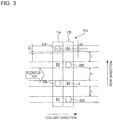
- Fig. 3 is a schematic diagram schematically illustrating a state of an example of the heat exchanger 50, as viewed in the direction of central axes of the heat transfer tubes.
- Fig. 4 is a schematic diagram schematically illustrating a state of another example of the heat exchanger 40, as viewed in the direction of the central axes of the heat transfer tubes.
- Fig. 5 is a schematic diagram schematically illustrating a state of another example of the heat exchanger 50, as viewed in the direction of the central axes of the heat transfer tubes.
- Fig. 6 is a schematic diagram schematically illustrating a state of the heat exchanger 50, as viewed in a direction perpendicular to the direction of the central axes of the heat transfer tubes.
- Fig. 3 is a schematic diagram schematically illustrating a state of an example of the heat exchanger 50, as viewed in the direction of central axes of the heat transfer tubes.
- Fig. 4 is a schematic diagram schematically illustrating a state of another example of the
- FIG. 7 is a schematic explanatory diagram for describing an example of specific numerical values of the heat exchanger 50.
- the heat exchanger 50 will be described in detail with reference to Figs. 3 to 7 .
- Figs. 3 and 4 illustrate the heat exchanger 50 having a two-column configuration
- Fig. 5 illustrates the heat exchanger 50 having a three-column configuration.
- the heat exchanger 50 includes a plurality of fins 1 arranged parallel to each other with predetermined gaps and a plurality of heat transfer tubes 2 that extend through the fins 1, and exchanges heat between the air flowing between the fins 1 and the refrigerant flowing inside the heat transfer tubes 2.
- the plurality of fins 1 are arranged in a direction parallel to the direction of flow of air, and have a multi-column configuration.
- Fig. 3 illustrates the fin 1 disposed on the upstream side of the flow of air as a fin 1A and the fin 1 disposed on the downstream side of the flow of air as a fin 1B. That is, the fins 1 have a two-column configuration in the example illustrated in Fig. 3 .
- Fig. 5 illustrates the fin 1 disposed on the upstream side of the flow of air as the fin 1A, the fin 1 disposed on the downstream side of the flow of air as a fin 1C, and the fin 1 disposed between the fin 1A and the fin 1C as the fin 1B. That is, the fins 1 have a three-column configuration in the example illustrated in Fig. 5 .
- the fin 1A corresponds to a "fin in the first column.”
- the fin 1B corresponds to a "fin in the second column.”
- the plurality of heat transfer tubes 2 are provided in a direction perpendicular to the direction of the flow of air through the fins 1.
- Fig. 3 illustrates the heat transfer tubes 2 extending through the fin 1A as heat transfer tubes 2A, and the heat transfer tubes 2 extending through the fin 1B as heat transfer tubes 2B. That is, the heat transfer tubes 2 are aligned in a multiple of rows in the example illustrated in Fig. 3 . That is, the heat transfer tubes 2 are aligned in a multiple of rows along a direction perpendicular to the column direction of the fins 1.
- Fig. 5 illustrates the heat transfer tubes 2 extending through the fin 1A as the heat transfer tubes 2A, the heat transfer tubes 2 extending through the fin 1B as the heat transfer tubes 2B, and the heat transfer tubes 2 extending through the fin 1C as heat transfer tubes 2C. That is, the heat transfer tubes 2 are aligned in a multiple of rows in the example illustrated in Fig. 5 .
- the direction perpendicular to the direction of the flow of air is defined as the "row direction.” Further, the heat transfer tubes 2A correspond to “first heat transfer tubes” of the present invention, and the heat transfer tubes 2B correspond to “second heat transfer tubes” of the present invention.
- a heat transfer promoting portion such as a slit is not provided between preceding and following ones of the heat transfer tubes 2 in the fins 1 to minimize the frost formation on parts of the air passages serving as ultimate release passages during the frost formation.
- the preceding and following ones of the heat transfer tubes 2 refer to, with reference to one of the heat transfer tubes 2A on the most upstream side of the flow of air for heat exchange, the heat transfer tube 2A and one or two of the heat transfer tubes 2B closest to the heat transfer tube 2A and positioned on the upper side and/or the lower side of the heat transfer tube 2A.
- the heat transfer promoting portion is not provided in a region between a lower end portion of one of the heat transfer tubes 2A and an upper end portion of the corresponding one of the heat transfer tubes 2B and a region between an upper end portion of one of the heat transfer tubes 2A and a lower end portion of the corresponding one of the heat transfer tubes 2B (three regions (second regions) L illustrated in Figs. 3 and 5 ).
- the heat exchanger 50 illustrated in Fig. 5 has the three-column configuration, and thus the regions L are extended in the column direction, and the heat transfer promoting portion is also not provided between a lower end portion of one of the heat transfer tubes 2C and an upper end portion of the corresponding one of the heat transfer tubes 2B.
- the region L is set to a region including at least a central portion of the region between the lower end portion of the one of the heat transfer tubes 2A and the upper end portion of the corresponding one of the heat transfer tubes 2B.
- the heat transfer promoting portion 3 such as a slit for producing the heat transfer promotion effect is formed in each of regions of the fins 1 not including the region L (first regions). In each of the regions of the fins 1 not including the region L, however, the heat transfer promoting portion 3 may be formed, and is not necessarily required to be formed. In the regions of the fins 1 not including the region L, the heat transfer promoting portion 3 is formed in a region of ⁇ 2 described below.
- the heat exchanger 50 can secure the region L as the air release passage, even when the formed frost grows.
- the region L serves as the air release passage, and thus the air reaches the downstream side of the heat exchanger 50, and the heat exchange continues. Consequently, the heat exchanger 50 is capable of minimizing the deterioration of the frost formation resistance.
- the heat transfer promoting portion 3 may be formed in each of the regions not including the region L, and when the heat transfer promoting portion 3 is formed, the heat transfer is promoted.
- Figs. 3 and 5 illustrate, as an example, the case in which the region L extends parallel to the column direction
- the region L is not required to extend strictly parallel to the column direction.
- the region L may be secured to slope from the upstream side toward the downstream side of the flow of air. With this configuration, the region L also serves as a drain passage when the frost thaws.
- the region L is only required to include a central portion of the region between the lower end portion of one of the heat transfer tubes 2A (the heat transfer tubes 2C) and the upper end portion of the corresponding one of the heat transfer tubes 2B and a central portion of the region between the upper end portion of one of the heat transfer tubes 2A (the heat transfer tubes 2C) and the lower end portion of the corresponding one of the heat transfer tubes 2B, and the region L may or may not extend parallel to the column direction.
- the region L may be provided on a part.
- the region between the heat transfer tube 2A in the uppermost row and the heat transfer tube 2B in the uppermost row may be set as the region L.
- the region between the heat transfer tube 2A in the lowermost row and the heat transfer tube 2B in the lowermost row may be set as the region L. That is, the number of regions L is not particularly limited. However, the deterioration of the frost formation resistance can be further reduced by setting the region L on both the upper sides and the lower sides of the heat transfer tubes, as in Figs. 3 and 5 .
- the drainage performance is enhanced owing to the absence of the heat transfer promoting portion 3, and the post-defrost drainage performance is improved.
- the size of the region L is preferably determined in consideration of a stagnation region length ( ⁇ 1) around each of the heat transfer tubes 2.
- ⁇ 1 the amount of formed frost is originally small owing to the separation of flow of air from a leading edge portion of the heat transfer tube 2. That is, the region L is set to the area excluding the portion of ⁇ 1.
- This configuration can form the heat transfer promoting portion 3 in the portion of ⁇ 1, and the heat transfer is promoted in the portion of ⁇ 1.
- the region L can secure the air release passage.
- the regions other than the region L is preferably determined in consideration of a stagnation region length ( ⁇ 2) of a slipstream behind each of the heat transfer tubes 2.
- a portion of ⁇ 2 is a slipstream portion behind the heat transfer tube 2, in which air originally does not flow smoothly. That is, the heat transfer promoting portion 3 is not formed in the region L, but is formed in each of the regions including ⁇ 2.
- the heat transfer promoting portion 3 is formed in the portion of ⁇ 2, and the heat transfer is promoted in the portion of ⁇ 2.
- the region L can secure the air release passage.
- the region L in this case may or may not include ⁇ 1.
- the region L secures the air release passage during the frost formation and minimizes the deterioration of the frost formation resistance. In the heat exchanger 50, consequently, the air passage is not blocked even during the frost formation, and thus the operation can be continued.
- Fig. 8 is a refrigerant circuit diagram schematically illustrating a basic refrigerant circuit configuration of a refrigeration cycle apparatus 100 according to Embodiment 2 of the present invention. A configuration and operation of the refrigeration cycle apparatus 100 will be described with reference to Fig. 8 .
- the refrigeration cycle apparatus 100 includes the heat source unit 60 and an indoor unit 70, and is capable of performing a heating energy supply operation (a heating operation, for example) or a cooling energy supply operation (a cooling operation, for example) by circulating refrigerant through component devices mounted in the heat source unit 60 and the indoor unit 70.
- a heating energy supply operation a heating operation, for example
- a cooling energy supply operation a cooling operation, for example
- the indoor unit (also referred to as use-side unit or load-side unit) 70 forms a part of the refrigeration cycle apparatus 100 together with the heat source unit 60. Further, the component devices mounted in the heat source unit 60 and the indoor unit 70 (the compressor 10, the heat exchanger 50, the expansion valve 12, and the use-side heat exchanger 71) are connected by pipes to thereby form a refrigerant circuit.
- the refrigeration cycle apparatus 100 is used in performing an air-conditioning operation in an air-conditioned space (such as an indoor space installed with the indoor unit 70). Further, for example, the refrigeration cycle apparatus 100 is used in performing a hot water supply operation of boiling water with the use-side heat exchanger 71. In Embodiment 2, however, a description will be given in the assumption that the refrigeration cycle apparatus 100 performs the air-conditioning operation.
- the heat source unit 60 is as described in Embodiment 1.
- the indoor unit 70 is equipped with the use-side heat exchanger 71 and an air-sending fan 72.
- the use-side heat exchanger (also referred to as indoor heat exchanger or load-side heat exchanger) 71 may be formed of a cross-fin, fin-and-tube heat exchanger similarly to the heat exchanger 50.
- the use-side heat exchanger 71 may be formed of a microchannel heat exchanger, a shell-and-tube heat exchanger, a heat-pipe heat exchanger, a double-pipe heat exchanger, a plate heat exchanger, or another type of heat exchanger.
- a case in which the use-side heat exchanger 71 exchanges heat with air and refrigerant will be described here as an example.
- the air-sending fan 72 is an air-sending unit formed of a through-flow fan (cross-flow fan), for example.
- the refrigerant When the compressor 10 is driven, the refrigerant is increased in pressure and discharged in a high-temperature, high-pressure state by the compressor 10.
- the refrigerant discharged from the compressor 10 is supplied to the use-side heat exchanger 71 and cooled into a low-temperature, high-pressure state through heat exchange with air.
- air for heating is supplied from the indoor unit 70, and the air-conditioned space is heated.
- the refrigerant flows out of the use-side heat exchanger 71 and is expanded through pressure reduction by the expansion valve 12 into a low-temperature, low-pressure state.
- the refrigerant is heated by the heat exchanger 50, and then returns to the compressor 10.
- the refrigerant When the compressor 10 is driven, the refrigerant is increased in pressure and discharged in a high-temperature, high-pressure state by the compressor 10.
- the refrigerant discharged from the compressor 10 is supplied to the heat exchanger 50 and cooled into a low-temperature, high-pressure state through heat exchange with air.
- the refrigerant flows out of the heat exchanger 50, and is expanded through pressure reduction by the expansion valve 12 into a low-temperature, low-pressure state.
- the refrigerant is heated by the use-side heat exchanger 71. In this process, air for cooling is supplied from the indoor unit 70, and the air-conditioned space is cooled.
- the refrigerant flowing out of the use-side heat exchanger 71 returns to the compressor 10.
- the refrigeration cycle apparatus 100 includes the heat exchanger 50, and thus is capable of securing the air release passages even during the frost formation and minimizing the deterioration of the frost formation resistance. Further, the air passages of the heat exchanger 50 are not blocked even during the frost formation on the heat exchanger 50, and thus the refrigeration cycle apparatus 100 is capable of continuously performing the heating energy supply operation.
- Embodiment 1 The numerical values described in Embodiment 1 are only illustrative, and the present invention is not limited to the described numerical values. Reference Signs List
Landscapes
- Engineering & Computer Science (AREA)
- Physics & Mathematics (AREA)
- Mechanical Engineering (AREA)
- General Engineering & Computer Science (AREA)
- Thermal Sciences (AREA)
- Geometry (AREA)
- Chemical & Material Sciences (AREA)
- Combustion & Propulsion (AREA)
- Heat-Exchange Devices With Radiators And Conduit Assemblies (AREA)
- Other Air-Conditioning Systems (AREA)
Applications Claiming Priority (1)
| Application Number | Priority Date | Filing Date | Title |
|---|---|---|---|
| PCT/JP2014/063003 WO2015173938A1 (fr) | 2014-05-15 | 2014-05-15 | Échangeur de chaleur et dispositif à cycle de réfrigération pourvu dudit échangeur |
Publications (2)
| Publication Number | Publication Date |
|---|---|
| EP3144624A1 true EP3144624A1 (fr) | 2017-03-22 |
| EP3144624A4 EP3144624A4 (fr) | 2018-02-14 |
Family
ID=54479507
Family Applications (1)
| Application Number | Title | Priority Date | Filing Date |
|---|---|---|---|
| EP14892097.8A Withdrawn EP3144624A4 (fr) | 2014-05-15 | 2014-05-15 | Échangeur de chaleur et dispositif à cycle de réfrigération pourvu dudit échangeur |
Country Status (5)
| Country | Link |
|---|---|
| US (1) | US20170074564A1 (fr) |
| EP (1) | EP3144624A4 (fr) |
| JP (1) | JP5864030B1 (fr) |
| CN (2) | CN106461350A (fr) |
| WO (1) | WO2015173938A1 (fr) |
Families Citing this family (2)
| Publication number | Priority date | Publication date | Assignee | Title |
|---|---|---|---|---|
| CN109661546A (zh) * | 2016-09-08 | 2019-04-19 | 三菱电机株式会社 | 热泵装置 |
| CN112236640B (zh) * | 2018-06-13 | 2022-05-10 | 三菱电机株式会社 | 热交换器、热交换器单元及制冷循环装置 |
Family Cites Families (26)
| Publication number | Priority date | Publication date | Assignee | Title |
|---|---|---|---|---|
| US1940804A (en) * | 1930-04-09 | 1933-12-26 | Karmazin Engineering Company | Radiator |
| FR1273767A (fr) * | 1960-11-17 | 1961-10-13 | Firsat Spa | Radiateur à tubes d'eau pour véhicules automobiles et autres applications analogues |
| US3266567A (en) * | 1962-12-20 | 1966-08-16 | Borg Warner | Heat exchanger |
| US4200149A (en) * | 1976-12-06 | 1980-04-29 | Murray Pechner | Heat exchanger with fluid turbulator |
| HU184377B (en) * | 1981-02-05 | 1984-08-28 | Huetoegepgyar | Motor cooler |
| JPS59229191A (ja) * | 1983-06-09 | 1984-12-22 | Matsushita Electric Ind Co Ltd | フイン付熱交換器 |
| US4723600A (en) * | 1985-05-10 | 1988-02-09 | Matsushita Refrigeration Company | Heat exchanger |
| JP2624336B2 (ja) * | 1989-06-28 | 1997-06-25 | 松下冷機株式会社 | フィン付熱交換器 |
| KR19990021475A (ko) * | 1997-08-30 | 1999-03-25 | 윤종용 | 핀형 열교환기 |
| KR100503407B1 (ko) * | 1999-03-09 | 2005-07-25 | 학교법인 포항공과대학교 | 핀 튜브형 열교환기 |
| KR100318229B1 (ko) * | 1999-07-28 | 2001-12-22 | 윤종용 | 공기조화기의 열교환기 |
| KR100347894B1 (ko) * | 2000-07-06 | 2002-08-09 | 엘지전자주식회사 | 세경관형 열교환기 |
| US20030150601A1 (en) * | 2002-02-08 | 2003-08-14 | Mando Climate Control Corporation | Heat exchanger fin for air conditioner |
| WO2004104506A1 (fr) * | 2003-05-23 | 2004-12-02 | Mitsubishi Denki Kabushiki Kaisha | Echangeur thermique du type tube a ailettes en plaques |
| JP2007010279A (ja) * | 2005-07-01 | 2007-01-18 | Daikin Ind Ltd | フィンチューブ型熱交換器 |
| CN101405558A (zh) * | 2006-03-23 | 2009-04-08 | 松下电器产业株式会社 | 翅片管式热交换器、热交换器用翅片及热泵装置 |
| JP2008215670A (ja) * | 2007-03-01 | 2008-09-18 | Matsushita Electric Ind Co Ltd | 伝熱フィン、フィンチューブ型熱交換器および冷凍サイクル装置 |
| JP5417718B2 (ja) * | 2007-03-07 | 2014-02-19 | ダイキン工業株式会社 | 熱交換器 |
| JP2009168317A (ja) * | 2008-01-15 | 2009-07-30 | Toshiba Carrier Corp | 熱交換器及び空気調和機 |
| JP4775429B2 (ja) * | 2008-05-26 | 2011-09-21 | パナソニック株式会社 | フィンチューブ型熱交換器 |
| JP4836996B2 (ja) * | 2008-06-19 | 2011-12-14 | 三菱電機株式会社 | 熱交換器及びこの熱交換器を備えた空気調和機 |
| JP2010255974A (ja) * | 2009-04-28 | 2010-11-11 | Daikin Ind Ltd | 熱交換器 |
| KR101451056B1 (ko) * | 2011-01-21 | 2014-10-16 | 다이킨 고교 가부시키가이샤 | 열교환기 및 공기 조화기 |
| JP5863463B2 (ja) * | 2012-01-06 | 2016-02-16 | 三菱重工業株式会社 | 熱交換器 |
| WO2013160950A1 (fr) * | 2012-04-26 | 2013-10-31 | 三菱電機株式会社 | Echangeur de chaleur et climatiseur |
| JP2014089018A (ja) * | 2012-10-31 | 2014-05-15 | Panasonic Corp | フィンチューブ熱交換器及びそれを備えた冷凍サイクル装置 |
-
2014
- 2014-05-15 CN CN201480078695.3A patent/CN106461350A/zh active Pending
- 2014-05-15 WO PCT/JP2014/063003 patent/WO2015173938A1/fr not_active Ceased
- 2014-05-15 CN CN202210159443.XA patent/CN114440328A/zh not_active Withdrawn
- 2014-05-15 US US15/308,389 patent/US20170074564A1/en not_active Abandoned
- 2014-05-15 JP JP2015518668A patent/JP5864030B1/ja not_active Expired - Fee Related
- 2014-05-15 EP EP14892097.8A patent/EP3144624A4/fr not_active Withdrawn
Also Published As
| Publication number | Publication date |
|---|---|
| JPWO2015173938A1 (ja) | 2017-04-20 |
| CN106461350A (zh) | 2017-02-22 |
| US20170074564A1 (en) | 2017-03-16 |
| CN114440328A (zh) | 2022-05-06 |
| WO2015173938A1 (fr) | 2015-11-19 |
| JP5864030B1 (ja) | 2016-02-17 |
| EP3144624A4 (fr) | 2018-02-14 |
Similar Documents
| Publication | Publication Date | Title |
|---|---|---|
| EP2851641B1 (fr) | Échangeur de chaleur, unité intérieure, et dispositif de cycle de réfrigération | |
| EP3037773B1 (fr) | Échangeur de chaleur, climatiseur, dispositif de cycle de réfrigération, et procédé de fabrication d'un échangeur de chaleur | |
| US9651317B2 (en) | Heat exchanger and air conditioner | |
| JP5195733B2 (ja) | 熱交換器及びこれを備えた冷凍サイクル装置 | |
| EP3156752B1 (fr) | Échangeur thermique | |
| US10156400B2 (en) | Heat exchanger and refrigeration cycle device | |
| EP2930456A1 (fr) | Appareil d'échange thermique à tubes plats, et unité extérieure pour climatiseur le comportant | |
| EP3021064B1 (fr) | Dispositif de pompe à chaleur | |
| EP3062037B1 (fr) | Échangeur thermique et dispositif à cycle de réfrigération utilisant ledit échangeur thermique | |
| KR20140106493A (ko) | 공기 조화기 | |
| CN108027181B (zh) | 热交换器 | |
| JP5951475B2 (ja) | 空気調和装置及びそれに用いられる室外熱交換器 | |
| CN108139088B (zh) | 空调 | |
| EP2980516B1 (fr) | Échangeur de chaleur et conditionneur d'air à cycle de réfrigération l'utilisant | |
| CN111902683B (zh) | 热交换器及制冷循环装置 | |
| JP5627635B2 (ja) | 空気調和機 | |
| EP3144624A1 (fr) | Échangeur de chaleur et dispositif à cycle de réfrigération pourvu dudit échangeur | |
| EP3141824B1 (fr) | Système de climatisation | |
| CN111512099B (zh) | 热交换器及制冷循环装置 | |
| JPWO2018142567A1 (ja) | 空気調和装置 | |
| WO2022215193A1 (fr) | Dispositif à cycle frigorifique | |
| JP2017203589A (ja) | 空気熱源式ヒートポンプユニット | |
| JP2016050719A (ja) | 熱交換器 |
Legal Events
| Date | Code | Title | Description |
|---|---|---|---|
| STAA | Information on the status of an ep patent application or granted ep patent |
Free format text: STATUS: THE INTERNATIONAL PUBLICATION HAS BEEN MADE |
|
| PUAI | Public reference made under article 153(3) epc to a published international application that has entered the european phase |
Free format text: ORIGINAL CODE: 0009012 |
|
| STAA | Information on the status of an ep patent application or granted ep patent |
Free format text: STATUS: REQUEST FOR EXAMINATION WAS MADE |
|
| 17P | Request for examination filed |
Effective date: 20161121 |
|
| AK | Designated contracting states |
Kind code of ref document: A1 Designated state(s): AL AT BE BG CH CY CZ DE DK EE ES FI FR GB GR HR HU IE IS IT LI LT LU LV MC MK MT NL NO PL PT RO RS SE SI SK SM TR |
|
| AX | Request for extension of the european patent |
Extension state: BA ME |
|
| DAX | Request for extension of the european patent (deleted) | ||
| A4 | Supplementary search report drawn up and despatched |
Effective date: 20180117 |
|
| RIC1 | Information provided on ipc code assigned before grant |
Ipc: F28F 1/32 20060101AFI20180111BHEP |
|
| STAA | Information on the status of an ep patent application or granted ep patent |
Free format text: STATUS: EXAMINATION IS IN PROGRESS |
|
| 17Q | First examination report despatched |
Effective date: 20200406 |
|
| GRAP | Despatch of communication of intention to grant a patent |
Free format text: ORIGINAL CODE: EPIDOSNIGR1 |
|
| STAA | Information on the status of an ep patent application or granted ep patent |
Free format text: STATUS: GRANT OF PATENT IS INTENDED |
|
| INTG | Intention to grant announced |
Effective date: 20240923 |
|
| STAA | Information on the status of an ep patent application or granted ep patent |
Free format text: STATUS: THE APPLICATION IS DEEMED TO BE WITHDRAWN |
|
| 18D | Application deemed to be withdrawn |
Effective date: 20250124 |