EP3144637B1 - Verfahren und system zur verbesserung des situationsbewusstseins unvorhergesehener gierbewegung auf einem drehflüglersystem - Google Patents
Verfahren und system zur verbesserung des situationsbewusstseins unvorhergesehener gierbewegung auf einem drehflüglersystem Download PDFInfo
- Publication number
- EP3144637B1 EP3144637B1 EP16185000.3A EP16185000A EP3144637B1 EP 3144637 B1 EP3144637 B1 EP 3144637B1 EP 16185000 A EP16185000 A EP 16185000A EP 3144637 B1 EP3144637 B1 EP 3144637B1
- Authority
- EP
- European Patent Office
- Prior art keywords
- rotorcraft
- lte
- wind direction
- wind
- degrees
- Prior art date
- Legal status (The legal status is an assumption and is not a legal conclusion. Google has not performed a legal analysis and makes no representation as to the accuracy of the status listed.)
- Active
Links
Images




Classifications
-
- B—PERFORMING OPERATIONS; TRANSPORTING
- B64—AIRCRAFT; AVIATION; COSMONAUTICS
- B64D—EQUIPMENT FOR FITTING IN OR TO AIRCRAFT; FLIGHT SUITS; PARACHUTES; ARRANGEMENT OR MOUNTING OF POWER PLANTS OR PROPULSION TRANSMISSIONS IN AIRCRAFT
- B64D45/00—Aircraft indicators or protectors not otherwise provided for
-
- B—PERFORMING OPERATIONS; TRANSPORTING
- B64—AIRCRAFT; AVIATION; COSMONAUTICS
- B64D—EQUIPMENT FOR FITTING IN OR TO AIRCRAFT; FLIGHT SUITS; PARACHUTES; ARRANGEMENT OR MOUNTING OF POWER PLANTS OR PROPULSION TRANSMISSIONS IN AIRCRAFT
- B64D47/00—Equipment not otherwise provided for
- B64D47/02—Arrangements or adaptations of signal or lighting devices
-
- G—PHYSICS
- G01—MEASURING; TESTING
- G01C—MEASURING DISTANCES, LEVELS OR BEARINGS; SURVEYING; NAVIGATION; GYROSCOPIC INSTRUMENTS; PHOTOGRAMMETRY OR VIDEOGRAMMETRY
- G01C23/00—Combined instruments indicating more than one navigational value, e.g. for aircraft; Combined measuring devices for measuring two or more variables of movement, e.g. distance, speed or acceleration
-
- B—PERFORMING OPERATIONS; TRANSPORTING
- B64—AIRCRAFT; AVIATION; COSMONAUTICS
- B64C—AEROPLANES; HELICOPTERS
- B64C27/00—Rotorcraft; Rotors peculiar thereto
- B64C27/04—Helicopters
-
- B—PERFORMING OPERATIONS; TRANSPORTING
- B64—AIRCRAFT; AVIATION; COSMONAUTICS
- B64D—EQUIPMENT FOR FITTING IN OR TO AIRCRAFT; FLIGHT SUITS; PARACHUTES; ARRANGEMENT OR MOUNTING OF POWER PLANTS OR PROPULSION TRANSMISSIONS IN AIRCRAFT
- B64D43/00—Arrangements or adaptations of instruments
-
- G—PHYSICS
- G05—CONTROLLING; REGULATING
- G05D—SYSTEMS FOR CONTROLLING OR REGULATING NON-ELECTRIC VARIABLES
- G05D1/00—Control of position, course, altitude or attitude of land, water, air or space vehicles, e.g. using automatic pilots
-
- G—PHYSICS
- G08—SIGNALLING
- G08G—TRAFFIC CONTROL SYSTEMS
- G08G5/00—Traffic control systems for aircraft
- G08G5/50—Navigation or guidance aids
-
- G—PHYSICS
- G08—SIGNALLING
- G08G—TRAFFIC CONTROL SYSTEMS
- G08G5/00—Traffic control systems for aircraft
- G08G5/50—Navigation or guidance aids
- G08G5/55—Navigation or guidance aids for a single aircraft
Definitions
- Embodiments of the subject matter described herein relate generally to rotorcraft display systems and, more particularly, to alerting a pilot to a potential unanticipated yaw.
- Unanticipated yaw (referred to herein as loss of tail rotor effectiveness (LTE)) causes a rotorcraft to twist around a vertical axis and requires a deft and vigilant response on the part of the rotorcraft pilot in order to safely recover.
- LTE loss of tail rotor effectiveness
- a rotorcraft is more susceptible to LTE when the pilot is operating in low airspeed and there is either a left crosswind (for rotorcraft with blades that rotate counter clockwise) or a tailwind.
- Right hand turns are more susceptible to LTE than left hand turns (again, for rotorcraft with blades that rotate counter clockwise). Therefore, during the course of rotorcraft operations, maintaining acute awareness of wind direction and wind velocity is essential.
- the rotorcraft pilot is heavily dependent upon information presented on the cockpit display, which typically comprises a primary flight display (PFD) and a multi-function display (MFD).
- the PFD and MFD visually convey information (e.g., flight path information, Navigational Aids (NAVAID), airspace information, terrain information, weather information, performance information, traffic information, and the like) obtained from various databases, sensors and transponders.
- information e.g., flight path information, Navigational Aids (NAVAID), airspace information, terrain information, weather information, performance information, traffic information, and the like
- the desired method and system evaluates rotorcraft airspeed, wind velocity, wind direction, and rotorcraft height above ground to predict several scenarios for LTE zones.
- the desired method and system overlays or superimposes simple intuitive symbology on the existing PFD and/or MFD to alert a pilot to a potential LTE.
- the desired method and system decreases pilot cognitive workload, and thus increases pilot situational awareness.
- US5890101A discloses a system, utilizing a neural network, for estimating helicopter airspeed in the low airspeed flight range of below about 50 knots using only fixed system parameters as inputs to the neural network.
- the method includes the steps of: (a) defining input parameters derivable from variable state parameters generated during flight of the helicopter and measurable in a nonrotating reference frame associated with the helicopter; (b) determining the input parameters and a corresponding helicopter airspeed at a plurality of flight conditions representing a predetermined low airspeed flight domain of the helicopter; (c) establishing a learned relationship between the determined input parameters and the corresponding helicopter airspeed wherein the relationship is represented by at least one nonlinear equation; (d) storing the at least one nonlinear equation in a memory onboard the helicopter; (e) measuring real time values of the variable state parameters during low airspeed flight of the helicopter; (f) calculating real time values of the input parameters; (g) storing the real time values of the input parameters in the memory; (h) processing the real time values of the input parameters
- the present invention provides a method for alerting a pilot of a rotorcraft (100) having a tail rotor to conditions sufficient to cause a loss of tail rotor effectiveness (LTE), according to claim 1 of the appended claims.
- the invention further provides a system for alerting a pilot of a rotorcraft having a tail rotor to a potential loss of tail rotor effectiveness (LTE), according to claim 6 of the appended claims.
- LTE tail rotor effectiveness
- a method for alerting a pilot to a potential loss of tail rotor effectiveness (LTE) on a rotorcraft having a tail rotor comprises: processing data from (i) an air data computer (ADC), (ii) a performance database, and (iii) a weather source, to determine whether the rotorcraft is within a LTE zone; and when it is determined that the rotorcraft is within the LTE zone, determining, with respect to the rotorcraft, a wind velocity in the LTE zone and a wind direction in the LTE zone; and overlaying, on a cockpit display, a visually distinguishable symbol indicative of the wind velocity in the LTE zone and the wind direction in the LTE zone.
- ADC air data computer
- a performance database e.g., a performance database
- a weather source e.g., a weather source
- the method comprises: processing data from an air data computer (ADC) and from a performance database to determine whether a forward airspeed of the rotorcraft is at or below a predetermined minimum forward airspeed threshold; processing data from a weather source to determine wind velocity and wind direction; determining that the rotorcraft is within a LTE zone when the forward airspeed of the rotorcraft is at or below the predetermined minimum forward airspeed threshold and either (i) the wind direction is from about 210 degrees to about 330 degrees with respect to the rotorcraft and the tail rotor is moving air in the same direction as the wind direction, or (ii) the wind direction is from about 285 degrees to about 315 degrees and the wind velocity is from about 10 Knots to about 30 Knots; and when it is determined that the rotorcraft is within a LTE zone, overlaying, on a primary flight display, a
- the system comprises: an air data computer (ADC) for providing rotorcraft airspeed and rotorcraft altitude; a performance database for providing rotorcraft data; a source of weather data for providing temperature and wind conditions; a display system comprising a cockpit display; and a processor coupled to the ADC, performance database, source of weather data, and the display system, the processor configured to: determine whether the rotorcraft is within a LTE zone based on the rotorcraft airspeed and the wind conditions, and when it is determined that the rotorcraft is within a LTE zone, (i) determine, with respect to the rotorcraft, a wind velocity in the LTE zone and a wind direction at the LTE zone, and (ii) command the display system to overlay, on the cockpit display, a visually distinguishable symbol indicative of the wind velocity in the LTE zone and the wind direction in the L
- an embodiment of a system or a component may employ various integrated circuit components, e.g., memory elements, digital signal processing elements, logic elements, look-up tables, or the like, which may carry out a variety of functions under the control of one or more microprocessors or other control devices.
- integrated circuit components e.g., memory elements, digital signal processing elements, logic elements, look-up tables, or the like, which may carry out a variety of functions under the control of one or more microprocessors or other control devices.
- Coupled means that one element/node/feature is directly or indirectly joined to (or directly or indirectly communicates with) another element/node/feature, and not necessarily mechanically.
- drawings may depict one exemplary arrangement of elements, additional intervening elements, devices, features, or components may be present in an embodiment of the depicted subject matter.
- certain terminology may also be used in the following description for the purpose of reference only, and thus are not intended to be limiting.
- FIG. 1 illustrates a first scenario when a rotorcraft may experience LTE.
- Rotorcraft 100 is centered within rotorcraft main rotor blade span 102.
- the circle representing the main rotor blade span 102 is demarked with degrees from zero degrees to 360 degrees.
- Wind velocity varies radially along the main rotor blade span 102, and
- FIG. 1 shows main rotor blade span 102 having wind velocity of 10 Knots ( 108 ), 15 Knots ( 106 ) and 30 Knots ( 104 ).
- a left "crosswind" or wind direction, with respect to the rotorcraft 100, between 285 degrees and 315 degrees is denoted as angle 110.
- a first vortex 112 is shown engulfing the rotorcraft tail rotor 105, and a second vortex 114 is shown toward the front of the rotorcraft 100.
- a first LTE zone may be described as meeting the following conditions: rotorcraft 100 has a forward speed at or below a predetermined minimum forward airspeed threshold, the cross wind direction is within angle 110 of the rotorcraft 100, and the rotorcraft tail rotor 105 is directing wind in the same direction as the cross wind.
- Another LTE zone may be defined more broadly, as when a left cross wind direction is within about 210 degrees to about 330 degrees from the rotorcraft 100 and rotorcraft 100 has a forward speed at or below a predetermined minimum forward airspeed threshold (A person with skill in the art will readily appreciate that rotorcraft having counter-clockwise blade rotation will be susceptible to winds coming from the right, and the same analysis will apply).
- the predetermined minimum forward airspeed threshold for option one and option two is 30 Knots.
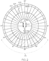
- FIG. 2 illustrates a second scenario for when a rotorcraft may experience LTE.
- the wind velocity from the rotorcraft main rotor blade span 102 is 5 Knots ( 208 ), 10 Knots ( 206 ), and 15 Knots ( 204 ).
- the rotorcraft 100 On occurrence of a "tailwind" or wind direction from about 120 degrees to about 240 degrees with respect to the rotorcraft 100 the rotorcraft 100 is in yet another LTE zone. In this scenario, rotorcraft 100 may weathervane into the wind direction if left unchecked.
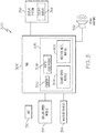
- FIG. 3 is a simplified block diagram of a system for alerting a pilot to a potential loss of tail rotor effectiveness 300, according to the embodiment.
- Air data computer (ADC) 310, Performance database and sensors 312, and weather sources 314 are coupled to processor 305.
- the processor 305 may reside within or be coupled to flight management system FMS 308, and it commands the display system 316 to generate and update cockpit display 318.
- Processor 305 comprises a weather model module 302, ground speed module 304, vortex logic module 306, and memory 320.
- processor 305 may comprise, or be associated with, any suitable number of individual microprocessors, flight control computers, navigational equipment, memories (such as memory 320 ), power supplies, storage devices, interface cards, and other standard components known in the art.
- the processor 305 may include or cooperate with any number of software models, software programs (e.g., rotorcraft display programs) or instructions designed to carry out the various methods, process tasks, calculations, and control/display functions described below.
- processor 305 may be included within a Flight Management System (FMS) 308 as shown in FIG. 3 , or may reside separately.
- FMS Flight Management System
- the FMS 308 may provide the processor 305 with wind models and predicted ground speed for each waypoint of a plurality of waypoints along a navigation route for a rotorcraft, and the processor 305 may, in response, predict a wind velocity and wind direction for each waypoint of the plurality of waypoints.
- cockpit display 318 typically take the form of a primary flight display (PFD) and a multi-function display (MFD), and include various analog (e.g., cathode ray tube) and digital (e.g., liquid crystal, active matrix, plasma, etc.) display devices.
- cockpit display 318 may assume the form of a Head-Down Display (HDD) or a Head-Up Display (HUD) included within a rotorcraft's Electronic Flight Instrument System (EFIS).
- HDD Head-Down Display
- HUD Head-Up Display
- processor 305 commands the display system 316 to produce 2D and 3D graphical displays on the PFD and MFD of the cockpit display 318 that visually provide a composite of navigation information pertaining to the host aircraft, weather, navigational route information, elevation, terrain, and potential LTE.
- Processor 305 may provide the cockpit display 318 with a composite image in a two dimensional format (e.g., as a moving map display), or a three dimensional format (e.g., as a perspective display), or in a hybrid format (e.g., in a picture-in-picture or split screen arrangement).
- Processor 305 may command an aural warning device 322, such as a speaker, to emit an aural warning when it is determined that there is a potential loss of tail rotor effectiveness.
- processor 305 determines that the rotorcraft is within a potential LTE zone and/or experiencing in ground effect (referred to herein as IGE and described in connection with FIG. 7 )
- the processor 305 commands the display system 316 to superimpose or overlay visually distinguishable symbology on symbols traditionally displayed on the existing cockpit display 318 to alert the pilot.
- processor 305 may also command an aural warning device 322, such as a speaker, to emit an aural warning.
- the visually distinguishable symbology prompts the pilot to begin correction by providing a simple, intuitive visual notification to the pilot.
- Various methods or techniques may be used to render visually distinguishable symbology, such as, but not limited to, depicting symbols using: highlighting, color, flashing, and dotted or broken lines.
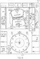
- FIG. 4 is a simplified illustration of a primary flight display (PFD) 400 with an alert for potential LTE, in accordance with a first option of the embodiment.
- PFD primary flight display
- a symbol for the rotorcraft 100 is shown in a compass header symbol 402 on the PFD 400 to show the heading direction of the rotorcraft 100.
- the processor 305 has determined that rotorcraft 100 is in a LTE zone. Responsive to determining that the rotorcraft 100 is in a LTE zone, a visually distinguishable symbol, in the form of a circle 406, is superimposed or overlaid on the PFD 400 such that circle 406 is within compass header symbol 402, and surrounds the rotorcraft 100.
- a visually distinguishable arrow 408 is superimposed or overlaid on PFD 400, and oriented to point at a location on circle 406 that indicates the determined "cross wind" wind direction with respect to rotorcraft 100.
- the magnitude of the wind velocity at the LTE zone is displayed at 410.
- the visually distinguishable arrow 408 may be removed from the PFD 400 when the following conditions are true: the forward speed of the rotorcraft 100 is no longer at or below a predetermined minimum forward airspeed threshold and the processor determines that the rotorcraft 100 is not in a LTE zone.
- FIG. 5 is a simplified illustration of a primary flight display (PFD) 500 with an alert for potential LTE, in accordance with a second option of the embodiment.
- PFD primary flight display
- FIG. 4 a symbol for the rotorcraft 100 is shown in a compass header symbol 402 traditionally rendered on the PFD 500 to show the heading direction of the rotorcraft 100.
- the processor 305 has determined that the rotorcraft 100 is in a LTE zone.
- a visually distinguishable symbol 502 is superimposed or overlaid on PFD 500, and oriented to point at compass header symbol 402 at a location on compass header symbol 402 that indicates the determined "cross wind" wind direction.
- Wind velocity at the LTE zone is displayed within the symbol 502.
- the magnitude of the wind velocity at the LTE zone is displayed within symbol 502.
- symbol 502 has the shape of a jagged arrow; however, other visually intuitive shapes are contemplated.
- FIG. 6 is a simplified illustration of a multi-function display (MFD) with an alert that a waypoint is in a potential LTE zone, in accordance with the embodiment.
- the FMS may provide wind models and predicted ground speed for each waypoint of a plurality of waypoints along a navigation route, and, in response, the processor 305 predicts a wind velocity and wind direction for each waypoint of the plurality of waypoints.
- the processor 305 has further determined that waypoint 602, along a projected flight course for rotorcraft 100, is in a LTE zone.
- waypoint 602 Responsive to determining that waypoint 602 is in a LTE zone, waypoint 602 is visually altered by overlaying waypoint 602 with a visually distinguishable symbol having a similar waypoint shape.
- symbol used for waypoint 602 has a similar waypoint shape as traditional waypoint symbols; however, other visually intuitive colors and shapes are contemplated.
- FIG. 7 is a simplified illustration of a primary flight display (PFD) 700 with an alert for an LTE zone in addition to an alert for "in ground effect” (IGE), in accordance with the embodiment.
- IGE is a phenomenon that influences rotorcraft performance that occurs while the rotorcraft is flying at a forward speed at or below a predetermined minimum forward airspeed threshold, and close to the ground (herein, "close to the ground” is defined as at or below a predetermined minimum height above ground).
- the rotorcraft may go in and out of experiencing IGE, in addition to flying into a LTE zone.
- processor 305 determines whether the rotorcraft 100 is experiencing IGE and initiates a visual alert when it is determined that the rotorcraft is experiencing IGE. When it is determined that the rotorcraft is not experiencing IGE, a displayed IGE symbol is removed from the cockpit display 318. In this manner, a pilot is alerted to a rotorcraft going in and out of experiencing IGE.
- the embodiment supports alerting the rotorcraft pilot of the LTE according to either option one ( FIG. 4 ) or option two ( FIG. 5 ), and then further alerting the pilot to IGE.
- symbol 502 alerts the pilot to the LTE zone, showing a corresponding 15 Knots of wind velocity.
- a visually distinguishable, translucent, symbol 702 is superimposed over the rotorcraft 100 symbol within the compass header symbol 402.
- symbol 702 is a circle with a slightly shaded center; however variations in symbol 702 are contemplated.
- a method and system for alerting a pilot to a potential unanticipated LTE with simple intuitive symbology on the cockpit display evaluates rotorcraft airspeed, wind velocity, wind direction, and rotorcraft height above ground to predict several scenarios for LTE zones.
- the desired method and system overlays or superimposes simple intuitive symbology on the existing PFD and/or MFD to alert a pilot to a potential LTE.
- the provided method and system decreases pilot cognitive workload, and thus increases pilot situational awareness.
Landscapes
- Engineering & Computer Science (AREA)
- Aviation & Aerospace Engineering (AREA)
- Radar, Positioning & Navigation (AREA)
- Remote Sensing (AREA)
- Physics & Mathematics (AREA)
- General Physics & Mathematics (AREA)
- Automation & Control Theory (AREA)
- Mechanical Engineering (AREA)
- Navigation (AREA)
- Processing Or Creating Images (AREA)
Claims (9)
- Verfahren, um den Piloten eines Drehflüglers (100) mit Heckrotor auf Bedingungen aufmerksam zu machen, die ausreichen, um einen Verlust der Heckrotor-Wirksamkeit (Loss of Tail rotor Effectiveness, LTE) zu bewirken, wobei das Verfahren umfasst:an einem Prozessor (305), der (i) mit einem Flugmanagementsystem (FMS) (308), einem Flugdatenrechner (Air Data Computer, ADC) (310), Wetterquellen (314), einer Leistungsdatenbank und Sensoren (312) verbunden ist, und (ii) ein Wettermodellmodul, ein Grundgeschwindigkeitsmodul, ein Wirbellogikmodul und einen Speicher umfasst,kontinuierliches Empfangen und Verarbeiten, für den Drehflügler (100), von Navigationsdaten, Windgeschwindigkeit und Windrichtung, Status des Drehflüglers und Flughöhe des Drehflüglers;Bestimmen, dass sich der Drehflügler in einer LTE-Zone befindet, definiert als Bedingungen ausgesetzt, die ausreichen, LTE zu verursachen, basierend auf (i) einer Kombination von Windgeschwindigkeit und Windrichtung bezogen auf eine Flugrichtung des Drehflüglers, einschließlich Bestimmen, ob die Windrichtung zum Drehflügler hin zwischen ungefähr 120 Grad und ungefähr 330 Grad bezogen auf den Drehflügler anliegt, und (ii) einer Vorwärts-Fluggeschwindigkeit des Drehflüglers bei oder unter einem vorbestimmten minimalen Schwellwert für die Vorwärts-Fluggeschwindigkeit;Überlagern, auf eine Cockpitanzeige (318), eines visuell unterscheidbaren Symbols (502), das die Windgeschwindigkeit in der LTE-Zone und die Windrichtung in der LTE-Zone anzeigt;wobei das Verfahren ferner umfasst, durch den Prozessor:Gewinnen, durch das FMS, von Windmodellen und vorhergesagter Grundgeschwindigkeit für jeden Wegepunkt von mehreren Wegepunkten entlang einer Navigationsroute und in Reaktion darauf Vorhersagen einer Windgeschwindigkeit und einer Windrichtung für jeden Wegepunkt der mehreren Wegepunkte, Bestimmen, dass ein Wegepunkt (602) entlang einem vorausberechneten Flugweg des Drehflüglers (100) in einer LTE-Zone liegt; undvisuelles Verändern, auf der Cockpitanzeige, eines Symbols, das den Wegepunkt anzeigt, in Reaktion auf das Bestimmen, dass der Wegepunkt in der LTE-Zone liegt.
- Verfahren nach Anspruch 1, wobei der vorbestimmte minimale Schwellwert für die Vorwärts-Fluggeschwindigkeit im Wesentlichen 30 Knoten beträgt.
- Verfahren nach Anspruch 1, wobei das Bestimmen, dass sich der Drehflügler in einer LTE-Zone befindet, ferner umfasst zu bestimmen, ob der Heckrotor Luft in derselben Richtung bewegt wie die Windrichtung, wenn die Windrichtung von ungefähr 210 Grad bis ungefähr 330 Grad bezogen auf den Drehflügler anliegt.
- Verfahren nach Anspruch 1, wobei das Verarbeiten der Daten zum Bestimmen, ob sich der Drehflügler in einer LTE-Zone befindet, ferner umfasst zu bestimmen, ob die Windgeschwindigkeit zwischen ungefähr zehn Knoten und ungefähr 30 Knoten beträgt und ob die Windrichtung von ungefähr 285 Grad bis ungefähr 315 Grad bezogen auf den Drehflügler anliegt.
- Verfahren nach Anspruch 1, ferner umfassend:Bestimmen, ob der Drehflügler (100) im Bodeneffekt (In-Ground Effect, IGE) fliegt; undÜberlagern, auf ein Drehflüglersymbol in einem Kompass-Steuerkurs-Symbol (402), eines visuell unterscheidbaren Symbols (702), das auf den IGE hinweist, wenn bestimmt wird, dass der Drehflügler (100) im IGE fliegt.
- System, um den Piloten eines Drehflüglers (100) mit Heckrotor auf einen möglichen Verlust der Heckrotor-Wirksamkeit (Loss of Tail rotor Effectiveness, LTE) aufmerksam zu machen, wobei das System umfasst:einen Flugdatenrechner (Air Data Computer, ADC) (310) zum Bereitstellen der Fluggeschwindigkeit des Drehflüglers und der Flughöhe des Drehflüglers;eine Leistungsdatenbank (312) zum Bereitstellen von Daten des Drehflüglers;eine Quelle für Wetterdaten (314) zum Bereitstellen von Temperatur- und Windbedingungen;ein Anzeigesystem (318), umfassend eine Cockpitanzeige (318) ;ein Flugmanagementsystem (FMS) (308); undeinen Prozessor (305), der mit dem ADC (310), der Leistungsdatenbank (312), der Quelle von Wetterdaten (314), dem Flugmanagementsystem (FMS) (308) und dem Anzeigesystem (318) verbunden ist, wobei der Prozessor ausgelegt ist zum:kontinuierlichen Verarbeiten der empfangenen Navigationsdaten, Windgeschwindigkeit und Windrichtung, Status des Drehflüglers und Flughöhe des Drehflüglers;Bestimmen, basierend auf (i) einer Kombination von Windgeschwindigkeit und Windrichtung bezogen auf eine Flugrichtung des Drehflüglers, einschließlich Bestimmen, ob die Windrichtung zum Drehflügler hin zwischen ungefähr 120 Grad und ungefähr 330 Grad bezogen auf den Drehflügler anliegt, und (ii) einer Vorwärts-Fluggeschwindigkeit des Drehflüglers bei oder unter einem vorbestimmten minimalen Schwellwert für die Vorwärts-Fluggeschwindigkeit, dass sich der Drehflügler in einer LTE-Zone befindet, definiert als Bedingungen ausgesetzt, die ausreichen, LTE zu verursachen;Überlagern, auf eine Cockpitanzeige (318), eines visuell unterscheidbaren Symbols (502), das die Windgeschwindigkeit in der LTE-Zone und die Windrichtung in der LTE-Zone anzeigt;wobei der Prozessor ferner ausgelegt ist zum:Gewinnen, durch das FMS, von Windmodellen und vorhergesagter Grundgeschwindigkeit für jeden Wegepunkt von mehreren Wegepunkten entlang einer Navigationsroute und in Reaktion darauf Vorhersagen einer Windgeschwindigkeit und einer Windrichtung für jeden Wegepunkt der mehreren Wegepunkte,Bestimmen, dass ein Wegepunkt (602) entlang einem vorausberechneten Flugweg des Drehflüglers (100) in einer LTE-Zone liegt; undvisuellen Verändern, auf der Cockpitanzeige, eines Symbols, das den Wegepunkt anzeigt, in Reaktion auf das Bestimmen, dass der Wegepunkt in der LTE-Zone liegt.
- System nach Anspruch 6, wobei der Prozessor (305) ferner ausgelegt ist zum:Bestimmen, wann der Drehflügler (100) im Bodeneffekt (In-Ground Effect, IGE) fliegt; undAnweisen des Anzeigesystems (318), (i) auf eine Cockpitanzeige (316) ein visuell unterscheidbares Symbol zu überlagern, das auf den IGE hinweist, während der Drehflügler im IGE fliegt.
- System nach Anspruch 6, wobei der Prozessor (305) ferner ausgelegt ist zum Bestimmen, dass sich der Drehflügler (100) in der LTE-Zone befindet, wenn eine Vorwärts-Fluggeschwindigkeit des Drehflüglers unter einem vorbestimmten minimalen Schwellwert für die Vorwärts-Fluggeschwindigkeit liegt und (i) die Windrichtung von ungefähr 210 Grad bis ungefähr 330 Grad anliegt und (ii) der Heckrotor Luft in derselben Richtung bewegt wie die Windrichtung.
- System nach Anspruch 6, wobei der Prozessor (305) ferner ausgelegt ist zum Bestimmen, dass sich der Drehflügler (100) in der LTE-Zone befindet, wenn die Windrichtung von ungefähr 285 Grad bis ungefähr 315 Grad anliegt und die Windgeschwindigkeit zwischen ungefähr 10 Knoten und ungefähr 30 Knoten beträgt.
Applications Claiming Priority (1)
| Application Number | Priority Date | Filing Date | Title |
|---|---|---|---|
| US14/833,641 US9802713B2 (en) | 2015-08-24 | 2015-08-24 | Method and system for improving situational awareness of unanticipated yaw on a rotorcraft system |
Publications (2)
| Publication Number | Publication Date |
|---|---|
| EP3144637A1 EP3144637A1 (de) | 2017-03-22 |
| EP3144637B1 true EP3144637B1 (de) | 2018-03-14 |
Family
ID=57209149
Family Applications (1)
| Application Number | Title | Priority Date | Filing Date |
|---|---|---|---|
| EP16185000.3A Active EP3144637B1 (de) | 2015-08-24 | 2016-08-19 | Verfahren und system zur verbesserung des situationsbewusstseins unvorhergesehener gierbewegung auf einem drehflüglersystem |
Country Status (3)
| Country | Link |
|---|---|
| US (1) | US9802713B2 (de) |
| EP (1) | EP3144637B1 (de) |
| CN (1) | CN106477057B (de) |
Cited By (1)
| Publication number | Priority date | Publication date | Assignee | Title |
|---|---|---|---|---|
| EP4685051A1 (de) | 2024-07-25 | 2026-01-28 | Airbus Helicopters | Drehflügler mit einem unvorhergesehenen gierverhinderungssystem |
Families Citing this family (10)
| Publication number | Priority date | Publication date | Assignee | Title |
|---|---|---|---|---|
| EP3436021A4 (de) | 2016-03-29 | 2019-11-06 | RespireRx Pharmaceuticals Inc. | Zusammensetzungen und verfahren zur behandlung von aufmerksamkeitsdefizitstörungen |
| US10216471B1 (en) * | 2017-08-17 | 2019-02-26 | Honeywell International Inc. | Aircraft systems and methods for unusual attitude recovery |
| US10399698B2 (en) * | 2017-09-16 | 2019-09-03 | Rockwell Collins, Inc. | Systems and methods for smart vision runway landing display |
| US11995998B2 (en) * | 2020-05-15 | 2024-05-28 | Hrl Laboratories, Llc | Neural network-based system for flight condition analysis and communication |
| US11181934B1 (en) | 2020-05-20 | 2021-11-23 | Honeywell International Inc. | Systems and methods for predicting ground effects along a flight plan |
| CN112242072B (zh) * | 2020-10-14 | 2022-01-21 | 中国联合网络通信集团有限公司 | 一种无人机领航方法和系统、领航无人机及号码管理平台 |
| US11801936B2 (en) * | 2021-01-19 | 2023-10-31 | Textron Innovations Inc. | Preventing helicopter loss of tail rotor effectiveness |
| CN116612669B (zh) * | 2023-05-05 | 2024-07-02 | 江苏省气象信息中心(江苏省气象档案馆) | 一种智慧航空实时气象数据分析预警方法及设备 |
| EP4653817A1 (de) * | 2024-05-24 | 2025-11-26 | Honeywell International Inc. | Verfahren und system zur automatischen warnung und führung zur vermeidung des verlusts der heckrotorwirksamkeit an einem drehflügler |
| US12589862B2 (en) * | 2024-05-24 | 2026-03-31 | Honeywell International Inc. | Method and system of automatic warnings and guidance for avoiding loss of tail rotor effectiveness on a rotorcraft |
Family Cites Families (14)
| Publication number | Priority date | Publication date | Assignee | Title |
|---|---|---|---|---|
| FR2610411B1 (fr) | 1987-02-04 | 1989-06-09 | Sfim | Procede et dispositif de mesure de la vitesse par rapport a l'air d'un helicoptere a basse vitesse |
| US5657009A (en) | 1991-10-31 | 1997-08-12 | Gordon; Andrew A. | System for detecting and viewing aircraft-hazardous incidents that may be encountered by aircraft landing or taking-off |
| US5751609A (en) | 1996-10-24 | 1998-05-12 | The United States Of America As Represented By The Secretary Of The Navy | Neural network based method for estimating helicopter low airspeed |
| US6466888B1 (en) | 1999-08-26 | 2002-10-15 | The United States Of America As Represented By The Secretary Of The Navy | Neural network system for estimation of aircraft flight data |
| US20070295857A1 (en) | 2005-11-16 | 2007-12-27 | Lloyd Peter G | Emergency Device |
| US8798814B1 (en) * | 2011-01-27 | 2014-08-05 | The Boeing Company | Vertical situation awareness for rotorcraft |
| FR2976395B1 (fr) | 2011-06-10 | 2013-08-02 | Eurocopter France | Systeme d'aide au pilotage et aeronef. |
| US9193450B2 (en) * | 2012-02-24 | 2015-11-24 | Bell Helicopter Textron Inc. | System and method for automation of rotorcraft entry into autorotation and maintenance of stabilized autorotation |
| KR101501133B1 (ko) | 2013-02-26 | 2015-03-11 | 한국항공우주산업 주식회사 | 회전익항공기의 임무컴퓨터를 위한 동적 실속 감지/경고장치 및 그 제어방법 |
| US9174730B2 (en) * | 2013-08-21 | 2015-11-03 | Sikorsky Aircraft Corporation | Automated rotating tail rotor control |
| US9037319B2 (en) * | 2013-09-24 | 2015-05-19 | Honeywell International Inc. | System and method for processing and displaying wake turbulence |
| FR3014411A1 (fr) * | 2013-12-10 | 2015-06-12 | Eurocopter France | Procede pour tendre a optimiser le bruit emis par un rotor auxiliaire et les performances d'un giravion, et un giravion |
| CN104035338B (zh) * | 2014-05-21 | 2016-08-31 | 中国人民解放军空军航空大学军事仿真技术研究所 | 一种多发动机的直升机动力系统动态匹配的仿真方法 |
| CA2897242C (en) | 2014-07-11 | 2022-08-16 | Cmc Electronics Inc. | System and method for detecting and alerting the user of an aircraft of an impendent adverse condition |
-
2015
- 2015-08-24 US US14/833,641 patent/US9802713B2/en active Active
-
2016
- 2016-08-19 EP EP16185000.3A patent/EP3144637B1/de active Active
- 2016-08-23 CN CN201610851898.2A patent/CN106477057B/zh active Active
Non-Patent Citations (1)
| Title |
|---|
| None * |
Cited By (1)
| Publication number | Priority date | Publication date | Assignee | Title |
|---|---|---|---|---|
| EP4685051A1 (de) | 2024-07-25 | 2026-01-28 | Airbus Helicopters | Drehflügler mit einem unvorhergesehenen gierverhinderungssystem |
Also Published As
| Publication number | Publication date |
|---|---|
| US9802713B2 (en) | 2017-10-31 |
| EP3144637A1 (de) | 2017-03-22 |
| CN106477057A (zh) | 2017-03-08 |
| US20170057658A1 (en) | 2017-03-02 |
| CN106477057B (zh) | 2021-10-08 |
Similar Documents
| Publication | Publication Date | Title |
|---|---|---|
| EP3144637B1 (de) | Verfahren und system zur verbesserung des situationsbewusstseins unvorhergesehener gierbewegung auf einem drehflüglersystem | |
| EP2899509B1 (de) | System und Verfahren zum Anzeigen von Flugbahninformationen in einem Drehflügler | |
| EP3125213B1 (de) | Flugzeugbordsysteme und verfahren zur identifizierung von beweglichen landeplattformen | |
| EP2993655B1 (de) | Flugzeugsysteme und verfahren zur anzeige von abstandsinformationen | |
| US9523580B2 (en) | System and method for aiding a pilot in locating an out of view landing site | |
| EP3444570B1 (de) | Flugzeugsysteme und -verfahren zur wiederherstellung nach unüblichen fluglagen | |
| CN105608932A (zh) | 用于显示跑道进场信息的系统和方法 | |
| EP4513143A1 (de) | Systeme und verfahren zur anzeige der flugzeugrollrate auf einer anzeige eines vertikal startenden und landenden flugzeugs | |
| US9340282B2 (en) | System and method for displaying vertical reference on a rotorcraft system | |
| CN105278540A (zh) | 用于在非正常飞行情况期间提高飞行员感知的系统和方法 | |
| US8831796B2 (en) | System and method for indicating a perspective cockpit field-of-view on a vertical situation display | |
| US20150348423A1 (en) | System and method for economizing flight expenditures during aircraft descent and approach | |
| EP3926607A1 (de) | Verfahren, systeme und vorrichtungen zur identifizierung und anzeige von anflugprozessen mit sekundärem landebahnzielpunkt (srap) | |
| CN105651305B (zh) | 用于集成导航的外向显示的系统和方法 | |
| US20180350258A1 (en) | System and method for adjusting the correlation between a visual display perspective and a flight path of an aircraft | |
| CN104575107B (zh) | 用于调节针对预期跑道的警报的系统和方法 | |
| CN105043374A (zh) | 用于显示上下文敏感注释的系统和方法 | |
| EP3309518B1 (de) | System und verfahren zum erzeugen und anzeigen eines flugzeugausrichtungseinsatzes |
Legal Events
| Date | Code | Title | Description |
|---|---|---|---|
| PUAI | Public reference made under article 153(3) epc to a published international application that has entered the european phase |
Free format text: ORIGINAL CODE: 0009012 |
|
| STAA | Information on the status of an ep patent application or granted ep patent |
Free format text: STATUS: REQUEST FOR EXAMINATION WAS MADE |
|
| 17P | Request for examination filed |
Effective date: 20160819 |
|
| AK | Designated contracting states |
Kind code of ref document: A1 Designated state(s): AL AT BE BG CH CY CZ DE DK EE ES FI FR GB GR HR HU IE IS IT LI LT LU LV MC MK MT NL NO PL PT RO RS SE SI SK SM TR |
|
| AX | Request for extension of the european patent |
Extension state: BA ME |
|
| GRAP | Despatch of communication of intention to grant a patent |
Free format text: ORIGINAL CODE: EPIDOSNIGR1 |
|
| STAA | Information on the status of an ep patent application or granted ep patent |
Free format text: STATUS: GRANT OF PATENT IS INTENDED |
|
| RIC1 | Information provided on ipc code assigned before grant |
Ipc: B64D 45/00 20060101ALI20170929BHEP Ipc: G01C 23/00 20060101AFI20170929BHEP Ipc: B64C 27/00 20060101ALI20170929BHEP Ipc: G08G 5/00 20060101ALI20170929BHEP Ipc: G05D 1/00 20060101ALI20170929BHEP Ipc: B64D 43/00 20060101ALI20170929BHEP |
|
| INTG | Intention to grant announced |
Effective date: 20171025 |
|
| GRAS | Grant fee paid |
Free format text: ORIGINAL CODE: EPIDOSNIGR3 |
|
| GRAA | (expected) grant |
Free format text: ORIGINAL CODE: 0009210 |
|
| STAA | Information on the status of an ep patent application or granted ep patent |
Free format text: STATUS: THE PATENT HAS BEEN GRANTED |
|
| AK | Designated contracting states |
Kind code of ref document: B1 Designated state(s): AL AT BE BG CH CY CZ DE DK EE ES FI FR GB GR HR HU IE IS IT LI LT LU LV MC MK MT NL NO PL PT RO RS SE SI SK SM TR |
|
| REG | Reference to a national code |
Ref country code: GB Ref legal event code: FG4D |
|
| REG | Reference to a national code |
Ref country code: CH Ref legal event code: EP Ref country code: AT Ref legal event code: REF Ref document number: 979345 Country of ref document: AT Kind code of ref document: T Effective date: 20180315 |
|
| REG | Reference to a national code |
Ref country code: IE Ref legal event code: FG4D |
|
| REG | Reference to a national code |
Ref country code: DE Ref legal event code: R096 Ref document number: 602016002001 Country of ref document: DE |
|
| REG | Reference to a national code |
Ref country code: NL Ref legal event code: MP Effective date: 20180314 |
|
| REG | Reference to a national code |
Ref country code: LT Ref legal event code: MG4D |
|
| PG25 | Lapsed in a contracting state [announced via postgrant information from national office to epo] |
Ref country code: CY Free format text: LAPSE BECAUSE OF FAILURE TO SUBMIT A TRANSLATION OF THE DESCRIPTION OR TO PAY THE FEE WITHIN THE PRESCRIBED TIME-LIMIT Effective date: 20180314 Ref country code: HR Free format text: LAPSE BECAUSE OF FAILURE TO SUBMIT A TRANSLATION OF THE DESCRIPTION OR TO PAY THE FEE WITHIN THE PRESCRIBED TIME-LIMIT Effective date: 20180314 Ref country code: LT Free format text: LAPSE BECAUSE OF FAILURE TO SUBMIT A TRANSLATION OF THE DESCRIPTION OR TO PAY THE FEE WITHIN THE PRESCRIBED TIME-LIMIT Effective date: 20180314 Ref country code: FI Free format text: LAPSE BECAUSE OF FAILURE TO SUBMIT A TRANSLATION OF THE DESCRIPTION OR TO PAY THE FEE WITHIN THE PRESCRIBED TIME-LIMIT Effective date: 20180314 Ref country code: NO Free format text: LAPSE BECAUSE OF FAILURE TO SUBMIT A TRANSLATION OF THE DESCRIPTION OR TO PAY THE FEE WITHIN THE PRESCRIBED TIME-LIMIT Effective date: 20180614 |
|
| REG | Reference to a national code |
Ref country code: AT Ref legal event code: MK05 Ref document number: 979345 Country of ref document: AT Kind code of ref document: T Effective date: 20180314 |
|
| REG | Reference to a national code |
Ref country code: FR Ref legal event code: PLFP Year of fee payment: 3 |
|
| PG25 | Lapsed in a contracting state [announced via postgrant information from national office to epo] |
Ref country code: RS Free format text: LAPSE BECAUSE OF FAILURE TO SUBMIT A TRANSLATION OF THE DESCRIPTION OR TO PAY THE FEE WITHIN THE PRESCRIBED TIME-LIMIT Effective date: 20180314 Ref country code: BG Free format text: LAPSE BECAUSE OF FAILURE TO SUBMIT A TRANSLATION OF THE DESCRIPTION OR TO PAY THE FEE WITHIN THE PRESCRIBED TIME-LIMIT Effective date: 20180614 Ref country code: GR Free format text: LAPSE BECAUSE OF FAILURE TO SUBMIT A TRANSLATION OF THE DESCRIPTION OR TO PAY THE FEE WITHIN THE PRESCRIBED TIME-LIMIT Effective date: 20180615 Ref country code: LV Free format text: LAPSE BECAUSE OF FAILURE TO SUBMIT A TRANSLATION OF THE DESCRIPTION OR TO PAY THE FEE WITHIN THE PRESCRIBED TIME-LIMIT Effective date: 20180314 Ref country code: SE Free format text: LAPSE BECAUSE OF FAILURE TO SUBMIT A TRANSLATION OF THE DESCRIPTION OR TO PAY THE FEE WITHIN THE PRESCRIBED TIME-LIMIT Effective date: 20180314 |
|
| PG25 | Lapsed in a contracting state [announced via postgrant information from national office to epo] |
Ref country code: ES Free format text: LAPSE BECAUSE OF FAILURE TO SUBMIT A TRANSLATION OF THE DESCRIPTION OR TO PAY THE FEE WITHIN THE PRESCRIBED TIME-LIMIT Effective date: 20180314 Ref country code: NL Free format text: LAPSE BECAUSE OF FAILURE TO SUBMIT A TRANSLATION OF THE DESCRIPTION OR TO PAY THE FEE WITHIN THE PRESCRIBED TIME-LIMIT Effective date: 20180314 Ref country code: AL Free format text: LAPSE BECAUSE OF FAILURE TO SUBMIT A TRANSLATION OF THE DESCRIPTION OR TO PAY THE FEE WITHIN THE PRESCRIBED TIME-LIMIT Effective date: 20180314 Ref country code: PL Free format text: LAPSE BECAUSE OF FAILURE TO SUBMIT A TRANSLATION OF THE DESCRIPTION OR TO PAY THE FEE WITHIN THE PRESCRIBED TIME-LIMIT Effective date: 20180314 Ref country code: RO Free format text: LAPSE BECAUSE OF FAILURE TO SUBMIT A TRANSLATION OF THE DESCRIPTION OR TO PAY THE FEE WITHIN THE PRESCRIBED TIME-LIMIT Effective date: 20180314 Ref country code: EE Free format text: LAPSE BECAUSE OF FAILURE TO SUBMIT A TRANSLATION OF THE DESCRIPTION OR TO PAY THE FEE WITHIN THE PRESCRIBED TIME-LIMIT Effective date: 20180314 Ref country code: IT Free format text: LAPSE BECAUSE OF FAILURE TO SUBMIT A TRANSLATION OF THE DESCRIPTION OR TO PAY THE FEE WITHIN THE PRESCRIBED TIME-LIMIT Effective date: 20180314 |
|
| PG25 | Lapsed in a contracting state [announced via postgrant information from national office to epo] |
Ref country code: SK Free format text: LAPSE BECAUSE OF FAILURE TO SUBMIT A TRANSLATION OF THE DESCRIPTION OR TO PAY THE FEE WITHIN THE PRESCRIBED TIME-LIMIT Effective date: 20180314 Ref country code: CZ Free format text: LAPSE BECAUSE OF FAILURE TO SUBMIT A TRANSLATION OF THE DESCRIPTION OR TO PAY THE FEE WITHIN THE PRESCRIBED TIME-LIMIT Effective date: 20180314 Ref country code: AT Free format text: LAPSE BECAUSE OF FAILURE TO SUBMIT A TRANSLATION OF THE DESCRIPTION OR TO PAY THE FEE WITHIN THE PRESCRIBED TIME-LIMIT Effective date: 20180314 Ref country code: SM Free format text: LAPSE BECAUSE OF FAILURE TO SUBMIT A TRANSLATION OF THE DESCRIPTION OR TO PAY THE FEE WITHIN THE PRESCRIBED TIME-LIMIT Effective date: 20180314 |
|
| REG | Reference to a national code |
Ref country code: DE Ref legal event code: R097 Ref document number: 602016002001 Country of ref document: DE |
|
| PG25 | Lapsed in a contracting state [announced via postgrant information from national office to epo] |
Ref country code: PT Free format text: LAPSE BECAUSE OF FAILURE TO SUBMIT A TRANSLATION OF THE DESCRIPTION OR TO PAY THE FEE WITHIN THE PRESCRIBED TIME-LIMIT Effective date: 20180716 |
|
| PLBE | No opposition filed within time limit |
Free format text: ORIGINAL CODE: 0009261 |
|
| STAA | Information on the status of an ep patent application or granted ep patent |
Free format text: STATUS: NO OPPOSITION FILED WITHIN TIME LIMIT |
|
| PG25 | Lapsed in a contracting state [announced via postgrant information from national office to epo] |
Ref country code: DK Free format text: LAPSE BECAUSE OF FAILURE TO SUBMIT A TRANSLATION OF THE DESCRIPTION OR TO PAY THE FEE WITHIN THE PRESCRIBED TIME-LIMIT Effective date: 20180314 |
|
| 26N | No opposition filed |
Effective date: 20181217 |
|
| PG25 | Lapsed in a contracting state [announced via postgrant information from national office to epo] |
Ref country code: SI Free format text: LAPSE BECAUSE OF FAILURE TO SUBMIT A TRANSLATION OF THE DESCRIPTION OR TO PAY THE FEE WITHIN THE PRESCRIBED TIME-LIMIT Effective date: 20180314 |
|
| PG25 | Lapsed in a contracting state [announced via postgrant information from national office to epo] |
Ref country code: MC Free format text: LAPSE BECAUSE OF FAILURE TO SUBMIT A TRANSLATION OF THE DESCRIPTION OR TO PAY THE FEE WITHIN THE PRESCRIBED TIME-LIMIT Effective date: 20180314 |
|
| PG25 | Lapsed in a contracting state [announced via postgrant information from national office to epo] |
Ref country code: LU Free format text: LAPSE BECAUSE OF NON-PAYMENT OF DUE FEES Effective date: 20180819 |
|
| REG | Reference to a national code |
Ref country code: BE Ref legal event code: MM Effective date: 20180831 |
|
| REG | Reference to a national code |
Ref country code: IE Ref legal event code: MM4A |
|
| PG25 | Lapsed in a contracting state [announced via postgrant information from national office to epo] |
Ref country code: IE Free format text: LAPSE BECAUSE OF NON-PAYMENT OF DUE FEES Effective date: 20180819 |
|
| PG25 | Lapsed in a contracting state [announced via postgrant information from national office to epo] |
Ref country code: BE Free format text: LAPSE BECAUSE OF NON-PAYMENT OF DUE FEES Effective date: 20180831 |
|
| PG25 | Lapsed in a contracting state [announced via postgrant information from national office to epo] |
Ref country code: MT Free format text: LAPSE BECAUSE OF NON-PAYMENT OF DUE FEES Effective date: 20180819 |
|
| PG25 | Lapsed in a contracting state [announced via postgrant information from national office to epo] |
Ref country code: TR Free format text: LAPSE BECAUSE OF FAILURE TO SUBMIT A TRANSLATION OF THE DESCRIPTION OR TO PAY THE FEE WITHIN THE PRESCRIBED TIME-LIMIT Effective date: 20180314 |
|
| PG25 | Lapsed in a contracting state [announced via postgrant information from national office to epo] |
Ref country code: CH Free format text: LAPSE BECAUSE OF NON-PAYMENT OF DUE FEES Effective date: 20190831 Ref country code: LI Free format text: LAPSE BECAUSE OF NON-PAYMENT OF DUE FEES Effective date: 20190831 |
|
| PG25 | Lapsed in a contracting state [announced via postgrant information from national office to epo] |
Ref country code: MK Free format text: LAPSE BECAUSE OF NON-PAYMENT OF DUE FEES Effective date: 20180314 Ref country code: HU Free format text: LAPSE BECAUSE OF FAILURE TO SUBMIT A TRANSLATION OF THE DESCRIPTION OR TO PAY THE FEE WITHIN THE PRESCRIBED TIME-LIMIT; INVALID AB INITIO Effective date: 20160819 |
|
| PG25 | Lapsed in a contracting state [announced via postgrant information from national office to epo] |
Ref country code: IS Free format text: LAPSE BECAUSE OF FAILURE TO SUBMIT A TRANSLATION OF THE DESCRIPTION OR TO PAY THE FEE WITHIN THE PRESCRIBED TIME-LIMIT Effective date: 20180714 |
|
| P01 | Opt-out of the competence of the unified patent court (upc) registered |
Effective date: 20230525 |
|
| PGFP | Annual fee paid to national office [announced via postgrant information from national office to epo] |
Ref country code: DE Payment date: 20250827 Year of fee payment: 10 |
|
| PGFP | Annual fee paid to national office [announced via postgrant information from national office to epo] |
Ref country code: GB Payment date: 20250826 Year of fee payment: 10 |
|
| PGFP | Annual fee paid to national office [announced via postgrant information from national office to epo] |
Ref country code: FR Payment date: 20250825 Year of fee payment: 10 |