EP3144712B1 - Bildbearbeitungsvorrichtung, bildbearbeitungsprogramm, bildbearbeitungsverfahren und mikroskopsystem - Google Patents
Bildbearbeitungsvorrichtung, bildbearbeitungsprogramm, bildbearbeitungsverfahren und mikroskopsystem Download PDFInfo
- Publication number
- EP3144712B1 EP3144712B1 EP15792978.7A EP15792978A EP3144712B1 EP 3144712 B1 EP3144712 B1 EP 3144712B1 EP 15792978 A EP15792978 A EP 15792978A EP 3144712 B1 EP3144712 B1 EP 3144712B1
- Authority
- EP
- European Patent Office
- Prior art keywords
- image
- picked
- illumination light
- contrast
- light
- Prior art date
- Legal status (The legal status is an assumption and is not a legal conclusion. Google has not performed a legal analysis and makes no representation as to the accuracy of the status listed.)
- Active
Links
Images









Classifications
-
- H—ELECTRICITY
- H04—ELECTRIC COMMUNICATION TECHNIQUE
- H04N—PICTORIAL COMMUNICATION, e.g. TELEVISION
- H04N23/00—Cameras or camera modules comprising electronic image sensors; Control thereof
- H04N23/95—Computational photography systems, e.g. light-field imaging systems
- H04N23/951—Computational photography systems, e.g. light-field imaging systems by using two or more images to influence resolution, frame rate or aspect ratio
-
- G—PHYSICS
- G06—COMPUTING OR CALCULATING; COUNTING
- G06T—IMAGE DATA PROCESSING OR GENERATION, IN GENERAL
- G06T5/00—Image enhancement or restoration
- G06T5/73—Deblurring; Sharpening
-
- G—PHYSICS
- G02—OPTICS
- G02B—OPTICAL ELEMENTS, SYSTEMS OR APPARATUS
- G02B21/00—Microscopes
- G02B21/06—Means for illuminating specimens
-
- G—PHYSICS
- G02—OPTICS
- G02B—OPTICAL ELEMENTS, SYSTEMS OR APPARATUS
- G02B21/00—Microscopes
- G02B21/24—Base structure
- G02B21/241—Devices for focusing
-
- G—PHYSICS
- G02—OPTICS
- G02B—OPTICAL ELEMENTS, SYSTEMS OR APPARATUS
- G02B21/00—Microscopes
- G02B21/36—Microscopes arranged for photographic purposes or projection purposes or digital imaging or video purposes including associated control and data processing arrangements
-
- G—PHYSICS
- G02—OPTICS
- G02B—OPTICAL ELEMENTS, SYSTEMS OR APPARATUS
- G02B21/00—Microscopes
- G02B21/36—Microscopes arranged for photographic purposes or projection purposes or digital imaging or video purposes including associated control and data processing arrangements
- G02B21/365—Control or image processing arrangements for digital or video microscopes
- G02B21/367—Control or image processing arrangements for digital or video microscopes providing an output produced by processing a plurality of individual source images, e.g. image tiling, montage, composite images, depth sectioning, image comparison
-
- G—PHYSICS
- G06—COMPUTING OR CALCULATING; COUNTING
- G06T—IMAGE DATA PROCESSING OR GENERATION, IN GENERAL
- G06T5/00—Image enhancement or restoration
- G06T5/50—Image enhancement or restoration using two or more images, e.g. averaging or subtraction
-
- H—ELECTRICITY
- H04—ELECTRIC COMMUNICATION TECHNIQUE
- H04N—PICTORIAL COMMUNICATION, e.g. TELEVISION
- H04N23/00—Cameras or camera modules comprising electronic image sensors; Control thereof
- H04N23/56—Cameras or camera modules comprising electronic image sensors; Control thereof provided with illuminating means
-
- H—ELECTRICITY
- H04—ELECTRIC COMMUNICATION TECHNIQUE
- H04N—PICTORIAL COMMUNICATION, e.g. TELEVISION
- H04N23/00—Cameras or camera modules comprising electronic image sensors; Control thereof
- H04N23/60—Control of cameras or camera modules
- H04N23/67—Focus control based on electronic image sensor signals
- H04N23/673—Focus control based on electronic image sensor signals based on contrast or high frequency components of image signals, e.g. hill climbing method
-
- H—ELECTRICITY
- H04—ELECTRIC COMMUNICATION TECHNIQUE
- H04N—PICTORIAL COMMUNICATION, e.g. TELEVISION
- H04N23/00—Cameras or camera modules comprising electronic image sensors; Control thereof
- H04N23/70—Circuitry for compensating brightness variation in the scene
- H04N23/74—Circuitry for compensating brightness variation in the scene by influencing the scene brightness using illuminating means
-
- H—ELECTRICITY
- H04—ELECTRIC COMMUNICATION TECHNIQUE
- H04N—PICTORIAL COMMUNICATION, e.g. TELEVISION
- H04N23/00—Cameras or camera modules comprising electronic image sensors; Control thereof
- H04N23/95—Computational photography systems, e.g. light-field imaging systems
-
- G—PHYSICS
- G06—COMPUTING OR CALCULATING; COUNTING
- G06T—IMAGE DATA PROCESSING OR GENERATION, IN GENERAL
- G06T2207/00—Indexing scheme for image analysis or image enhancement
- G06T2207/10—Image acquisition modality
- G06T2207/10024—Color image
-
- G—PHYSICS
- G06—COMPUTING OR CALCULATING; COUNTING
- G06T—IMAGE DATA PROCESSING OR GENERATION, IN GENERAL
- G06T2207/00—Indexing scheme for image analysis or image enhancement
- G06T2207/10—Image acquisition modality
- G06T2207/10056—Microscopic image
-
- G—PHYSICS
- G06—COMPUTING OR CALCULATING; COUNTING
- G06T—IMAGE DATA PROCESSING OR GENERATION, IN GENERAL
- G06T2207/00—Indexing scheme for image analysis or image enhancement
- G06T2207/10—Image acquisition modality
- G06T2207/10141—Special mode during image acquisition
- G06T2207/10152—Varying illumination
-
- G—PHYSICS
- G06—COMPUTING OR CALCULATING; COUNTING
- G06T—IMAGE DATA PROCESSING OR GENERATION, IN GENERAL
- G06T2207/00—Indexing scheme for image analysis or image enhancement
- G06T2207/20—Special algorithmic details
- G06T2207/20212—Image combination
- G06T2207/20221—Image fusion; Image merging
-
- H—ELECTRICITY
- H04—ELECTRIC COMMUNICATION TECHNIQUE
- H04N—PICTORIAL COMMUNICATION, e.g. TELEVISION
- H04N23/00—Cameras or camera modules comprising electronic image sensors; Control thereof
- H04N23/60—Control of cameras or camera modules
- H04N23/63—Control of cameras or camera modules by using electronic viewfinders
Definitions
- the present technology relates to an image processing apparatus, an image processing program, and an image processing method that perform image processing on an image picked up via a microscope optical system, and to a microscopic system that picks up an image as an image processing target.
- a microscopic image obtained by picking up an image of an observation target object via a microscope is desired to have a high resolution.
- the NA (numerical aperture) of the microscope optical system is very large, and it is technically difficult to eliminate the chromatic aberration (focus deviation due to the wavelength band).
- the chromatic aberration focus deviation due to the wavelength band.
- Patent Document 1 an image processing apparatus that superimposes a plurality of images one on another and combines them with each other to obtain a combined image is described.
- This apparatus is assumed to generate a combined image (panorama image) from images picked up by an imaging apparatus such as a camera, and is not used for scientific verification such as a microscopic image.
- EP2312858 discloses an image processing apparatus for generating an image with high resolution over a diffraction limit includes: an image input unit which receives red image data and green image data which represent images of an object by red light and green light, respectively, and a blue image data which represents an image of the object by blue light having a wavelength shorter than those of the red and the green light; and an image processing unit which corrects the red and the green image data by adding thereon a spatial high frequency component contained in the blue image data, and the image input unit receives, as the blue image data, image data which is generated by light receiving elements provided at intervals shorter than a size of a smallest area that the red and the green light can converge.
- Patent Document 1 Japanese Patent No. 4814840 Summary
- an object of the present technology to provide an image processing apparatus, an image processing program, an image processing method, and a microscopic system that are capable of acquiring a high-resolution image that is suitable for scientific verification as defined in the appended claims.
- an image processing apparatus includes an image conversion unit and an image generation unit.
- the image conversion unit converts a first picked-up image and a second picked-up image into frequency components, the first picked-up image being obtained by picking up an image of an observation target object with first illumination light via a microscope optical system, the second picked-up image being obtained by picking up an image of the observation target object with second illumination light via the microscope optical system, the second picked-up image having a contrast in a low frequency band lower than that of the first picked-up image and a contrast in a high frequency band higher than that of the first picked-up image.
- the image generation unit combines a low frequency component of the first picked-up image and a high frequency component of the second picked-up image with each other to generate a composite image.
- the image processing apparatus is capable of generating a high-resolution image that includes a low frequency component of the first picked-up image having a high contrast in the low frequency component and a high frequency component of the second picked-up image having a high contrast in the high frequency band, and has a high contrast in all frequency bands.
- the low frequency component of the first picked-up image and the high frequency component of the second picked-up image are those optically resolved with the microscope optical system, and the composite image is suitable for scientific verification.
- the first illumination light may be narrow band light in a wavelength band longer than that of the second illumination light
- the second illumination light may be narrow band light in a wavelength band shorter than that of the first illumination light
- the focal position of the microscope optical system is slightly displaced for each wavelength band and does not completely match.
- the focal position of the microscope optical system completely matches, and it is possible to acquire resolution performance higher than that of white light.
- the wavelength band of illumination light from which the highest contrast can be acquired is different for the spatial frequency of the observation target object, the contrast of the low frequency band is high in the case of illumination light in a long frequency band, and the contrast of the high frequency band is high in the case of illumination light in a short frequency band.
- the first picked-up image having a high contrast in the low frequency band can be acquired by picking up an image of the observation target object with the first illumination light that is narrow band light in a long wavelength band
- the second picked-up image having a high contrast in the high frequency band can be acquired by picking up an image of the observation target object with the second illumination light that is narrow band light in a short wavelength band.
- a high resolution image having a high contrast in all frequency bands can be generated from the low frequency component of the first picked-up image and the high frequency component of the second picked-up image, it is possible to pick up the first picked-up image and the second picked-up image that can be used for generating a high-resolution image by using two kinds of narrow band light having different wavelength bands as the illumination light.
- the first illumination light may be red light
- the second illumination light may be blue light
- Red light and blue light are the farthest away from each other in the wavelength band of visible light, and the difference of frequency properties between them is large. Specifically, in the case where the magnification of the microscope optical system is equal to or larger than a predetermined magnification, the contrast in the low frequency band of the red light tends to be high and the contrast in the high frequency band of the blue light tends to be high. Therefore, by using the red light as the first illumination light and the blue light as the second illumination light, more significant effects can be acquired as compared with the case where narrow band light in two wavelength bands more close to each other is used as the first illumination light and the second illumination light.
- the first illumination light may have an illumination NA lower than that of the second illumination light
- the second illumination light may have an illumination NA higher than that of the first illumination light
- illumination NA illumination NA
- the tendency of the contrast for the frequency band is different. Specifically, illumination light having a low illumination NA has a high contrast in the low frequency band, and illumination light having a high illumination NA has a high contrast in the high frequency band. Therefore, also by using illumination light having a low illumination NA as the first illumination light and illumination light having a high illumination NA as the second illumination light, it is possible to generate the first picked-up image having a high contrast in the low frequency band and the second picked-up image having a high contrast in the high frequency band.
- the image conversion unit may convert the first picked-up image into a spatial frequency area image to generate a first spatial frequency area image, and the second picked-up image into a spatial frequency area image to generate a second spatial frequency area image, and the image generation unit may generate the composite image from a low frequency area of the first spatial frequency area image and a high frequency area of the second spatial frequency area image.
- the image generation unit may generate a combined image obtained by combining the low frequency area and the high frequency area with each other, and generate the composite image by converting the combined image into a spatial area image.
- the low frequency component of the first picked-up image (the low frequency area of the first spatial frequency area image) and the high frequency component of the second picked-up image (the high frequency area of the second spatial frequency area image) can be combined with each other at the stage of the spatial frequency area image, it is possible to generate a composite image including the low frequency component of the first picked-up image and the high frequency component of the second picked-up image by converting (e.g., inverse Fourier transform) it into a spatial area.
- the image generation unit may generate a low frequency component image obtained by converting the low frequency area into a spatial area image and a high frequency component image obtained by converting the high frequency area into a spatial area image, and generate the composite image by adding the low frequency component image and the high frequency component image to each other.
- an image processing program includes an image conversion unit and an image generation unit.
- the image conversion unit converts a first picked-up image and a second picked-up image into frequency components, the first picked-up image being obtained by picking up an image of an observation target object with first illumination light via a microscope optical system, the second picked-up image being obtained by picking up an image of the observation target object with second illumination light via the microscope optical system, the second picked-up image having a contrast in a low frequency band lower than that of the first picked-up image and a contrast in a high frequency band higher than that of the first picked-up image.
- the image generation unit combines a low frequency component of the first picked-up image and a high frequency component of the second picked-up image with each other to generate a composite image.
- an image processing method includes converting, by an image conversion unit, a first picked-up image and a second picked-up image into frequency components, the first picked-up image being obtained by picking up an image of an observation target object with first illumination light via a microscope optical system, the second picked-up image being obtained by picking up an image of the observation target object with second illumination light via the microscope optical system, the second picked-up image having a contrast in a low frequency band lower than that of the first picked-up image and a contrast in a high frequency band higher than that of the first picked-up image.
- An image generation unit combines a low frequency component of the first picked-up image and a high frequency component of the second picked-up image with each other to generate a composite image.
- a microscopic system includes an illumination lamp, a microscope optical system, an imaging unit, and an image conversion unit.
- the illumination lamp applies first illumination light and second illumination light.
- the image conversion unit converts a first picked-up image and a second picked-up image into frequency components, the first picked-up image being obtained by picking up an image of an observation target object with the first illumination light via the microscope optical system, the second picked-up image being obtained by picking up an image of the observation target object with the second illumination light via the microscope optical system, the second picked-up image having a contrast in a low frequency band lower than that of the first picked-up image and a contrast in a high frequency band higher than that of the first picked-up image.
- the image generation unit combines a low frequency component of the first picked-up image and a high frequency component of the second picked-up image with each other to generate a composite image.
- the image processing apparatus is capable of generating the composite image that is a high-resolution image from the first picked-up image and the second picked-up image as described above.
- the microscopic system may further including: a focus adjustment mechanism that adjust a focal position of the microscope optical system; and a control unit that controls the focus adjustment mechanism to cause the microscope optical system to focus on the observation target object under irradiation of the first illumination light, and cause the microscope optical system to focus on the observation target object under irradiation of the second illumination light.
- control unit adjusts the focal position under irradiation of the first illumination light and under the second illumination light, it is possible to improve the contrast of the first picked-up image and the second picked-up image, i.e., the contrast of the composite image.
- the microscopic system may further include a control unit that controls a light amount of the first illumination light and the second illumination light so that exposure of the first picked-up image and exposure of the second picked-up image match.
- an image processing apparatus As described above, according to the present technology, it is possible to provide an image processing apparatus, an image processing program, an image processing method, and a microscopic system that are capable of acquiring a high-resolution image that is suitable for scientific verification. Note that the effect described here is not necessarily limitative and may be any effect described in the present disclosure.
- a microscopic system 100 according to a first embodiment of the present technology will be described.
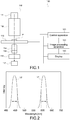
- Fig. 1 is a schematic diagram showing the configuration of the microscopic system 100 according to this embodiment.
- the microscopic system 100 includes a microscope 110, a control apparatus 120, an image processing apparatus 130, and a display 140. On the microscope 110, an observation target object P is placed.
- the microscope 110 generates an enlarged microscopic image of the observation target object P.
- the microscope 110 includes an illumination lamp 111, an illumination optical system 112, a stage 113, an objective lens 114, an imaging lens 115, a focus adjustment mechanism 116, and an imaging unit 117.
- a direction along the optical axis of the microscope 110 is a Z direction
- one direction perpendicular to the Z direction is an X direction
- a direction perpendicular to the Z direction and the X direction is a Y direction.
- the illumination lamp 111 applies illumination light to the observation target object P.
- the illumination lamp 111 is configured to be capable of applying two kinds of illumination light.
- the two kinds of illumination light applied by the illumination lamp 111 are referred to as a first illumination light L1 and a second illumination light L2.
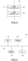
- Fig. 2 is a schematic diagram showing an example of the spectra of the first illumination light L1 and the second illumination light L2.
- the first illumination light L1 is narrow band light having a wavelength band longer than that of the second illumination light L2.
- the wavelength band of the first illumination light L1 is included in the red light band of not less than 570 nm and not more than 700 nm.
- the first illumination light L1 may have at least the peak wavelength in the red light band.
- the first illumination light L1 can be narrow band light having a full width at half maximum of the spectrum (width shown by dashed lines in the figure) of not less than 10 nm and not more than 100 nm.
- the second illumination light L2 is narrow band light having a wavelength band shorter than that of the first illumination light.
- the wavelength band of the second illumination light is included in the blue light band of not less than 400 nm and not more than 500 nm.
- the second illumination light L2 may have at least the peak wavelength in the blue light band.
- the second illumination light L2 can be narrow band light having a full width at half maximum of the spectrum (width shown by dashed lines in the figure) of not less than 10 nm and not more than 100 nm.
- the wavelength bands of the first illumination light L1 and the second illumination light L2 are not limited to those described above as long as the wavelength band of the first illumination light L1 is longer than that of the second illumination light L2 and the wavelength band of the second illumination light L2 is shorter than that of the first illumination light L1.
- the second illumination light L2 may be in the green light band (not less than 500 nm and not more than 570 nm).
- the wavelength of the first illumination light L1 is close to the wavelength band of the second illumination light L2, the effects of the present technology are reduced. Therefore, the wavelength bands are favorably apart from each other to some extent.
- the first illumination light L1 and the second illumination light L2 are each favorably narrow band light having a full width at half maximum of the spectrum of not less than 10 nm and not more than 100 nm. This is because the resolution of a picked-up image under the illumination light is reduced when the full width at half maximum exceeds 100 nm. Because the refractive index of light is slightly different for each wavelength band, the focal position is displaced for each wavelength, and it is difficult to strictly bring the light in all wavelengths into focus on the same position when a full width at half maximum exceeds 100 nm. On the other hand, if the full width at half maximum is less than 10 nm, interference is generated in the observation target object P. Therefore, the full width at half maximum is favorably not less than 10 nm.
- first illumination light L1 and the second illumination light L2 as being included in the red wavelength band and the blue wavelength band, respectively.
- the illumination lamp 111 is configured to be capable of separately applying the first illumination light L1 and the second illumination light L2.
- the illumination lamp 111 may include a light source for the first illumination light L1 and a light source for the second illumination light L2.
- the light source an LED (Light Emitting Diode), a laser, and the like, which have a relatively narrow wavelength band of emitted light, can be used.
- the illumination lamp 111 may be a single light source, and may be configured to be capable of applying the first illumination light L1 and the second illumination light L2 by using a switchable color filter or the like.
- the illumination optical system 112 collimates the first illumination light L1 and the second illumination light L2 applied from the illumination lamp 111.
- the illumination optical system 112 is, for example, a Kohler illumination optical system.
- the stage 113 supports the observation target object P.
- the stage 113 is, for example, an XY stage that can be moved to the X direction and the Y direction, or an XYZ stage that can be moved to the X direction, the Y direction, and the Z direction.
- the objective lens 114 optically enlarges an image of the observation target object P.
- the image of the observation target object P is formed by the first illumination light L1 or the second illumination light L2 applied to the observation target object.
- the objective lens 114 has, for example, a general configuration.
- the imaging lens 115 forms an image of the observation target object P enlarged by the objective lens 114 on the imaging surface of the imaging unit 117.
- the imaging lens 115 has, for example, a general configuration.
- the objective lens 114 and the imaging lens 115 constitute the microscope optical system of the microscope 110.
- the configuration of the microscope optical system is not limited to that described here, and it only has to enlarge the image of the observation target object P and form an image on the imaging surface of the imaging unit 117.
- the focus adjustment mechanism 116 adjusts the focal position of the microscope optical system. Specifically, as shown in Fig. 1 , the focus adjustment mechanism 116 can adjust the focal position by moving the Z position of the objective lens 114. Further, the focus adjustment mechanism 116 may be incorporated in the stage 113 and adjust the focal position by moving the Z position of the stage 113. The focus adjustment mechanism 116 can adjust the focal position under control of the control apparatus 120. This will be described later.
- the imaging unit 117 picks up an image of the observation target object P formed by the imaging lens 115.
- the imaging unit 117 includes a solid-state image sensor such as a CCD (Charge Coupled Device) and a CMOS (Complementary Metal-Oxide Semiconductor).
- the imaging unit 117 only has to be capable of picking up an image of (photoelectrically converting) at least light in the wavelength bands of the first illumination light L1 and the second illumination light L2, and may include a general image sensor that can perform color imaging.
- the microscope 110 has the above-mentioned configuration. Note that although the microscope 110 has been shown as a transmission bright field microscope in Fig. 1 , the present technology can be applied to any kind of microscope that is capable of optically enlarging the image of the observation target object such as a reflection bright field microscope, a phase-contrast microscope, and a fluorescence microscope.
- the control apparatus 120 controls the respective units of the microscope 110. As shown in Fig. 1 , the control apparatus 120 can be connected to the illumination lamp 111, the stage 113, and the focus adjustment mechanism 116, and control them. The control apparatus 120 can control the light amount of the first illumination light L1 and the second illumination light L2 applied from the illumination lamp 111 or the focal position of the microscope optical system although the details will be described later.
- the image processing apparatus 130 performs image processing on the image picked up by the imaging unit 117.
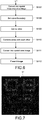
- Fig. 3 is a schematic diagram showing the functional configuration of the image processing apparatus 130
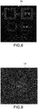
- Fig. 4 is a schematic diagram showing a typical hardware configuration of the image processing apparatus 130.
- the image processing apparatus 130 includes an image conversion unit 131 and an image generation unit 132. Description of the configurations of the image conversion unit 131 and the image generation unit 132 will be made in detail along with description of the operation of the microscopic system 100.
- the image conversion unit 131 and the image generation unit 132 have the functional configuration achieved by cooperation of the hardware configuration shown in Fig. 4 with a program.
- the image processing apparatus 130 includes, as a hardware configuration, a CPU 133, a memory 134, a storage 135, and an input/output unit 136. These are connected to each other via a bus 138.
- the CPU (Central Processing Unit) 133 controls another configuration in accordance with a program stored in the memory 134, performs data processing in accordance with the program, and stores the processing results in the memory 134.
- the CPU 133 can be a microprocessor.
- the memory 134 stores a program executed by the CPU 133 and data.
- the memory 134 can be a RAM (Random Access Memory) .
- the storage 135 stores a program or data.
- the storage 135 can be an HDD (Hard disk drive) or an SSD (solid state drive).
- the input/output unit 136 receives an input to the image processing apparatus 130, and supplies an output of the image processing apparatus 130 to the outside.
- the input/output unit 136 includes an input device such as a keyboard and a mouse, an output device such as the display 140, and a connection interface such as a network.
- the hardware configuration of the image processing apparatus 130 is not limited to that described here, and it only has to achieve the above-mentioned functional configuration of the image processing apparatus 130. Further, a part or whole of the above-mentioned hardware configuration may be on a network.
- the display 140 is connected to the input/output unit 136 of the image processing apparatus 130, and displays an image output from the image processing apparatus 130. Further, the display 140 may be connected also to the imaging unit 117 of the microscope 110, and may directly display an image picked up by the imaging unit 117.
- the microscopic system 100 has the above-mentioned configuration.
- the control apparatus 120 and the image processing apparatus 130 may be one apparatus having the functions thereof. Further, one or both of the control apparatus 120 and the image processing apparatus 130 may be mounted on the microscope 110.
- FIGs. 5 and 6 are each a flowchart showing the operation of the microscopic system 100.
- the control apparatus 120 controls the illumination lamp 111, and the first illumination light L1 is applied from the illumination lamp 111 (St101).
- the first illumination light L1 is narrow band light in a long wavelength band.
- the first illumination light L1 is collimated by the illumination optical system 112, transmitted through the observation target object P, and enlarged by the objective lens 114, and an image thereof is formed on the imaging surface of the imaging unit 117 by the imaging lens 115.
- control apparatus 120 controls the focus adjustment mechanism 116 to adjust the focal position of the microscope optical system (the objective lens 114 and the imaging lens 115) (St102).
- the control apparatus 120 is capable of controlling the focus adjustment mechanism 116 to adjust the focal position such that the contrast of an image picked up by the imaging unit 117 is maximized.
- the control apparatus 120 may set the focal position to a position displaced by a predetermined amount from the focal position at that time.
- the control apparatus 120 is capable of determining the shift amount of the focal position depending on the wavelength band of the first illumination light L1 by measuring or calculating in advance how much the focal position is displaced with light in a particular wavelength band with respect to the focal position with white light.
- the user may operate the control apparatus 120 while referring to a picked-up image displayed on the display 140 such that the contrast of the picked-up image is maximized, to perform the adjustment of the focal position manually.
- the control apparatus 120 controls the imaging unit 117 to pick up an image (St103).
- this picked up image is referred to as a first picked-up image G1.
- Fig. 7 shows an example of the first picked-up image G1. Because this image has been obtained by picking up an image of a resolving power chart including lines having a predetermined width and space (example of the observation target object P), and has been picked up in the wavelength band of the first illumination light L1 (red wavelength band), the white area of the image shown in Fig. 7 is actually red.
- the imaging unit 117 supplies the first picked-up image G1 to the image processing apparatus 130.
- the control apparatus 120 controls the illumination lamp 111 to apply the second illumination light L2 from the illumination lamp 111 (St104).
- the first illumination light L1 is narrow band light in a short wavelength band.
- the second illumination light L2 is collimated by the illumination optical system 112, transmitted through the observation target object P, and enlarged by the objective lens 114, and an image thereof is formed on the imaging surface of the imaging unit 117 by the imaging lens 115.
- control apparatus 120 controls the focus adjustment mechanism 116 to adjust the focal position of the microscope optical system (the objective lens 114 and the imaging lens 115) (St105). Since the wavelength bands of the first illumination light L1 and the second illumination light L2 are slightly different from each other, their focal positions are slightly different from each other. By adjusting the focal position again, it is possible to improve the resolution of the picked-up image under irradiation of the second illumination light L2.
- control apparatus 120 is capable of controlling the focus adjustment mechanism 116 to adjust the focal position such that the contrast of the image picked up by the imaging unit 117 is maximized. Further, the control apparatus 120 may displace the focal position by a predetermined amount from the focal position adjusted at the time of the first illumination light L1 depending on the wavelength band of the second illumination light L2. Further, the user may adjust the focal position manually.
- the control apparatus 120 controls the imaging unit 117 to pick up an image (St106).
- this picked up image is referred to as a second picked-up image G2.
- Fig. 8 shows an example of the second picked-up image G2. Because this image has been obtained by picking up an image of a resolving power chart (example of the observation target object P) as described above, and has been picked up in the wavelength band of the second illumination light L2 (blue wavelength band), the white area of the image shown in Fig. 8 is actually blue.
- the imaging unit 117 supplies the second picked-up image G2 to the image processing apparatus 130.
- the first picked-up image G1 is picked up under irradiation of the first illumination light L1
- the second picked-up image G2 is picked up under irradiation of the second illumination light L2. Note that the pick-up order of the first picked-up image G1 and the second picked-up image G2 may be reversed.
- the control apparatus 120 may control the illumination lamp 111 to adjust the light amount of the first illumination light L1 and the second illumination light L2. This is because when brightness (exposure) of the first illumination light L1 and the second illumination light L2 significantly differs, a problem occurs in image processing to be described later. Specifically, the control apparatus 120 can control the illumination lamp 111 such that the average brightness value of the picked-up image under irradiation of the first illumination light L1 and the average brightness value of the picked-up image under irradiation of the second illumination light L2 match.
- the image conversion unit 131 converts the first picked-up image G1 and the second picked-up image G2 into a spatial frequency area image (St107).
- the first picked-up image G1 and the second picked-up image G2 are each obtained by picking up an image of the observation target object P and are each a spatial area image.
- the image conversion unit 131 can perform frequency analysis on the first picked-up image G1 and the second picked-up image G2, and convert the first picked-up image G1 into the first spatial frequency area image and the second picked-up image G2 into the second spatial frequency area image.
- the image conversion unit 131 can convert both picked-up images into a spatial frequency area image.
- FFT fast Fourier transform
- the image conversion unit 131 may use another frequency analysis algorithm to convert the first picked-up image G1 and the second picked-up image G2 into a spatial frequency area image.
- the image conversion unit 131 can decompose the first picked-up image G1 and the second picked-up image G2 into frequency components, and arrange the frequency components such that a low frequency component is arranged on the center of the image and a high frequency component is arranged on the edge of the image, thereby generating a spatial frequency area image.
- Fig. 9 shows a first spatial frequency area image H1 converted from the first picked-up image G1
- Fig. 10 shows a second spatial frequency area image H2 generated from the second picked-up image G2.
- Figs. 9 and 10 show images that are obtained by applying the fast Fourier transform to the first picked-up image G1 and the second picked-up image G2, respectively, and generated such that a low frequency component is arranged on the center of the image and a high frequency component is arranged on the edge of the image.
- the image generation unit 132 sets a cutout boundary for the first spatial frequency area image H1 and the second spatial frequency area image H2 (St108).
- Fig. 11 is a diagram showing a cutout boundary S1 set for the first spatial frequency area image H1
- Fig. 12 is a diagram showing a cutout boundary S2 set for the second spatial frequency area image H2.
- the image generation unit 132 can set, as the cutout boundary S1 and the cutout boundary S2, a circle with the same diameter around the image center in both of the spatial frequency area images.
- the distance from the image center in both of the spatial frequency area images is a frequency, and a circle around the center of the image corresponds to a particular frequency.
- This frequency may be determined in advance.
- the image generation unit 132 may determine the frequency by analyzing the first spatial frequency area image H1 and the second spatial frequency area image H2.
- the frequency is favorably a frequency that is the same as or close to a reverse frequency to be described later.
- the cutout boundary does not necessarily need to have a circular shape, and may have a rectangular shape or elliptical shape around the center of the image.
- a circle around the center of a spatial frequency area image corresponds to a particular frequency, and thus is used favorably.
- Fig. 13 is a conceptual diagram showing cutting out of a low frequency area from the first spatial frequency area image H1.
- the image generation unit 132 can cut out an inner peripheral area (area shown by a diagonal line) of the cutout boundary S1 in the first spatial frequency area image H1. Because the center of the first spatial frequency area image H1 is a low frequency component as described above, the inner peripheral area of the cutout boundary S is an area of a low frequency component. Hereinafter, this area will be described as a low frequency area F1.
- Fig. 14 is a conceptual diagram showing cutting out of a high frequency area from the second spatial frequency area image H2.
- the image generation unit 132 can cut out an outer peripheral area (area shown by a diagonal line) of the cutout boundary S2 in the second spatial frequency area image H2.
- the outer peripheral area of the cutout boundary S2 is an area of a high frequency component.
- this area will be described as a high frequency area F2.
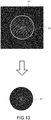
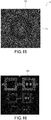
- Fig. 15 is a schematic diagram showing a combined image U. As shown in the figure, the image generation unit 132 combines the low frequency area F1 and the high frequency area F2 with each other such that the cutout boundary S1 and the cutout boundary S2 (see Figs. 11 and 12 ) match.
- the image generation unit 132 converts the combined image U into a spatial area image (St111). Specifically, the image generation unit 132 can apply the inverse Fourier transform to the combined image U to convert both images into a spatial frequency area image. For the inverse Fourier transform, the inverse fast Fourier transform (IFFT) can be used. Alternatively, the image conversion unit 131 may use another frequency analysis algorithm to convert the combined image U into a spatial area image.
- IFFT inverse fast Fourier transform
- the image conversion unit 131 may use another frequency analysis algorithm to convert the combined image U into a spatial area image.
- a composite image is generated.
- Fig. 16 shows a composite image G3 thus generated.
- the image generation unit 132 can display the composite image G3 on, for example, the display 140, and present it to the user.
- the image conversion unit 131 generates the first spatial frequency area image H1 and the second spatial frequency area image H2 in which the center of the image is a low frequency component and the edge of the image is a high frequency component (St107) in the above description
- the spatial frequency area image may be generated in another format.
- the image conversion unit 131 may generate a spatial frequency area image such that the center of the image is a high frequency component and the edge of the image is a low frequency component.
- the image generation unit 132 can set the cutout boundary S1 and the cutout boundary S2 on a predetermined frequency position or in a predetermined shape in the first spatial frequency area image H1 and the second spatial frequency area image H2, and cut out the low frequency area F1 from the first spatial frequency area image H1 and the high frequency area F2 from the second spatial frequency area image H2.
- the microscopic system 100 applies the first illumination light L1 and the second illumination light L2, and picks up the first picked-up image G1 and the second picked-up image G2.
- frequency properties of the illumination light differ depending on the wavelength band thereof.
- Figs. 17 and 18 show the results obtained by applying illumination light to a resolving power chart, picking up an image via the microscope optical system, and calculating a spatial frequency response by the slanted-edge method.
- the horizontal axis represents the line density (line/mm) of the resolving power chart, i.e., spatial frequency
- the vertical axis represents the contrast.
- Fig. 17 shows the results obtained from the microscope optical system including an objective lens (NA 0.45) having a magnification of ⁇ 20
- Fig. 18 shows the results obtained from the microscope optical system including an objective lens (NA 0.75) having a magnification of ⁇ 60.
- Fig. 19 shows the spectrum of illumination light.
- the illumination is narrow band illumination using an LED light source, and has the peak wavelengths at 466 nm (blue), 521 nm (green), and 638 nm (red).
- the contrasts of blue color (B) and green color (G) are generally higher than the contrast of red color (R). Specifically, it is found that in this magnification, an image having a higher contrast can be picked up by using, as the illumination light, blue light or green light as compared with the case where red light is used.
- the contrast of red color (R) is higher than that of blue color (B) or green color (G) in a spatial frequency lower than approximately 1000 line/mm while the contrast of blue color (B) or green color (G) is higher than that of red color (R) in a spatial frequency higher than approximately 1000 line/mm.
- This spatial frequency in which the contrast of red color (R) and the contrast of blue color (B) are reversed is referred to as a reverse frequency T1.
- a spatial frequency in which the contrast of blue color and the contrast of green color are reversed is referred to as a reverse frequency T2.
- the wavelength band of the illumination light in which the highest contrast is acquired differs for each spatial frequency of the observation target object, an image picked up with red illumination light has a higher contrast in a low frequency band, and an image picked up with blue or green illumination light has a higher contrast in a high frequency band, in the case where the magnification of the microscope optical system is high.
- the first picked-up image G1 is picked up under irradiation of the first illumination light L1 (e.g., red light), which is narrow band light in a long wavelength band
- the second picked-up image G2 is picked up under irradiation of the second illumination light L2 (e.g., blue light), which is narrow band light in a short wavelength band. Therefore, the first picked-up image G1 has a higher contrast in a low frequency band than that of the second picked-up image G2, and the second picked-up image G2 has a higher contrast in a high frequency band than that of the first picked-up image G1.
- the image generation unit 132 converts the first picked-up image G1 into the first spatial frequency area image H1, and cuts out the low frequency area F1 therefrom.
- the low frequency area F1 is obtained by extracting components in a low frequency band having a high contrast in the first picked-up image G1.
- the image generation unit 132 converts the second picked-up image G2 into the second spatial frequency area image H2, and cuts out the high frequency area F2 therefrom.
- the high frequency area F2 is obtained by extracting components in a high frequency band having a high contrast in the second picked-up image G2.
- the combined image U generated by the image generation unit 132 combining the low frequency area F1 and the high frequency area F2 with each other is a spatial frequency area image including a low frequency component of the first picked-up image G1 and a high frequency component of the second picked-up image G2.
- the composite image G3 obtained by converting the combined image U into a spatial area image includes a low frequency component of the first picked-up image G1 and a high frequency component of the second picked-up image G2.
- the low frequency band of the first picked-up image G1 has a contrast higher than that of the low frequency band of the second picked-up image G2, and the high frequency band of the second picked-up image G2 has a contrast higher than that of the high frequency band of the first picked-up image G1. Therefore, the composite image G3 has a higher contrast in the high frequency band than that of the first picked-up image G1, and a higher contrast in the low frequency band than that of the second picked-up image G2. Specifically, the composite image G3 has a high contrast in all frequency bands (a low frequency band and a high frequency band), and has good resolution.
- the focal point of the microscope optical system is adjusted in the first picked-up image G1 and the second picked-up image G2, respectively.
- the focal position is displaced depending on the wavelength band. Therefore, a picked-up image with light that is not narrow band light as the illumination light has a lower contrast in the low frequency band and the high frequency band than that of the first picked-up image G1 and the second picked-up image G2, respectively.
- the composite image G3 has a higher contrast in all frequency bands than that of a picked-up image with light that is not narrow band light as the illumination light, and has good resolution.
- the microscopic system 100 it is possible to acquire a high-resolution image of the observation target object P.
- images that have been optically resolved under irradiation of the first illumination light L1 and the second illumination light L2 are rendered as the composite image G3. Therefore, because the composite image G3 is not one obtained by rendering images that have not optically been resolved by image processing, and scientific accuracy is maintained, it can be used for scientific verification without inconvenience.
- a microscopic system 200 according to a second embodiment of the present technology will be described. Note that in the description of this embodiment, the same configurations as those of the microscopic system 100 according to the first embodiment will be denoted by the same reference symbols, and a description thereof will be omitted.
- Fig. 20 is a schematic diagram showing the configuration of the microscopic system 200 according to this embodiment. Because the microscopic system 200 has the same configuration as that of the microscopic system 100 according to the first embodiment except that it includes an image processing apparatus 230, the configuration of the image processing apparatus 230 will be described.
- the image processing apparatus 230 performs image processing on an image picked up by the imaging unit 117.
- Fig. 21 is a schematic diagram showing the functional configuration of the image processing apparatus 130.
- the image processing apparatus 230 includes an image conversion unit 231 and an image generation unit 232. Description of the configurations of the image conversion unit 231 and the image generation unit 232 will be made in detail along with description of the operation of the microscopic system 200.
- the hardware configuration of the image processing apparatus 230 can be the same as that of the image processing apparatus 130 according to the first embodiment (see Fig. 4 ).
- the image conversion unit 231 and the image generation unit 232 have the functional configuration achieved by cooperation of the hardware configuration thereof with a program.
- the operation of the microscopic system 200 will be described.
- the operation to picking up of the second picked-up image G2 is the same as that of the first embodiment.
- the microscopic system 200 adjusts the focal position under irradiation of the first illumination light L1 that is narrow band light in a long wavelength band, and picks up the first picked-up image G1.
- the microscopic system 200 adjusts the focal position under irradiation of the second illumination light L2 that is narrow band light in a short wavelength, and picks up the second picked-up image G2.
- the image conversion unit 231 converts the first picked-up image G1 and the second picked-up image G2 into a spatial frequency area image (St201).
- the first picked-up image G1 and the second picked-up image G2 are each obtained by picking an image of the observation target object P, and are each a spatial area image.
- the image conversion unit 231 can perform frequency analysis on the first picked-up image G1 and the second picked-up image G2, and convert the first picked-up image G1 into the first spatial frequency area image and the second picked-up image G2 into the second spatial frequency area image.
- the image conversion unit 231 can convert both images into a spatial frequency area image.
- FFT fast Fourier transform
- the image conversion unit 231 may use another frequency analysis algorithm to convert the first picked-up image G1 and the second picked-up image G2 into a spatial frequency area image.
- the image conversion unit 131 can decompose the first picked-up image G1 and the second picked-up image G2 into frequency components, and arrange the frequency components such that a low frequency component is arranged on the center of the image and a high frequency component is arranged on the edge of the image, thereby generating a spatial frequency area image.
- the image conversion unit 231 generates the first spatial frequency area image H1 (see Fig. 9 ) from the first picked-up image G1, and the second spatial frequency area image H2 (see Fig. 10 ) from the second picked-up image G2.
- the image generation unit 232 sets a mask range for the first spatial frequency area image H1 and the second spatial frequency area image H2 (St202).
- Fig. 23 is a diagram showing a mask range M1 set for the first spatial frequency area image H1
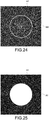
- Fig. 24 is a diagram showing a mask range M2 set for the second spatial frequency area image H2.
- the image generation unit 232 can set, as the mask range M1 and the mask range M2, a circle with the same diameter around the image center in both of the spatial frequency area images.
- the distance from the image center in both of the spatial frequency area images is a frequency, and a circle around the center of the image corresponds to a particular frequency.
- This frequency may be determined in advance.
- the image generation unit 232 may determine the frequency by analyzing the first spatial frequency area image H1 and the second spatial frequency area image H2.
- the frequency is favorably a frequency that is close to the above-mentioned reverse frequency.
- the mask range does not necessarily need to have a circular shape, and may have a rectangular shape or elliptical shape around the center of the image.
- a circle around the center of a spatial frequency area image corresponds to a particular frequency, and thus is used favorably.
- Fig. 25 is a schematic diagram showing masking performed on the first spatial frequency area image H1.
- the image generation unit 232 applies a masking A1 to the mask range M1 in the first spatial frequency area image H1.
- the masking A1 shown with white color represents that frequency components in the masking A1 are transmitted therethrough (used for the next conversion into a spatial area image).
- Fig. 26 is a schematic diagram showing masking performed on the second spatial frequency area image H2.
- the image generation unit 232 applies a masking A2 to the mask range M2 in the second spatial frequency area image H2.
- the masking A2 shown with black color represents that frequency components in the masking A2 are blocked (not used for the next conversion into a spatial area image).
- the image generation unit 232 converts the first spatial frequency area image H1 and the second spatial frequency area image H2 into a spatial area image (St204).
- the image generation unit 232 applies the inverse Fourier transform such as IFFT to the first spatial frequency area image H1 to convert the first spatial frequency area image H1 into a spatial frequency area image.
- IFFT inverse Fourier transform
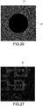
- Fig. 27 shows a low frequency component image B1 converted from the first spatial frequency area image H1.
- the image generation unit 232 applies the inverse Fourier transform such as IFFT also to the second spatial frequency area image H2 to convert the second spatial frequency area image H2 into a spatial frequency area image.
- the masking A2 is applied to the second spatial frequency area image H2
- only the high frequency area located at the vicinity of the edge of the second spatial frequency area image H2 is converted by the inverse Fourier transform, and a high frequency component image including only the high frequency components of the second spatial frequency area image H2 is generated.
- Fig. 28 shows a high frequency component image B2 converted from the second spatial frequency area image H2.
- the image generation unit 232 adds the low frequency component image B1 and the high frequency component image B2 (St205) to each other. Specifically, the image generation unit 232 adds the brightness value of the low frequency component image B1 and the brightness value of the high frequency component image B2 to each other for each pixel coordinate. Accordingly, a composite image (see Fig. 16 ) is generated.
- the image generation unit 232 can display the generated composite image on, for example, the display 140, and present it to the user.
- the image conversion unit 231 generates the first spatial frequency area image H1 and the second spatial frequency area image H2 in which the center of the image is a low frequency component and the edge of the image is a high frequency component (St201) in the above description
- the spatial frequency area image may be generated in another format.
- the image conversion unit 231 may generate a spatial frequency area image such that the center of the image is a high frequency component and the edge of the image is a low frequency component.
- the image generation unit 232 can set the mask range M1 and the mask range M2 on a predetermined frequency position or in a predetermined shape in the first spatial frequency area image H1 and the second spatial frequency area image H2, and perform masking on the high frequency components in the first spatial frequency area image H1 and the low frequency components in the second spatial frequency area image H2.
- a picked-up image is converted into a spatial frequency area image (St107), the low frequency area and the high frequency area are combined with each other on the spatial frequency area (St110), and it is converted into a spatial area image (Still).
- a picked-up image is converted into a spatial frequency area image (St201), masking is performed on the spatial frequency area image (St203) before it is converted into a spatial area image (St204), and the spatial area image is added (St205).
- both embodiments equivalent results are obtained because the difference between them is only that the low frequency components and the high frequency components are combined with each other either in the spatial frequency area or in the spatial area. Therefore, by using the microscopic system 200, it is possible to acquire a high-resolution image of the observation target object P. In addition, because both images maintain scientific accuracy, it is possible to use the image for scientific verification without inconvenience.
- third illumination light that has a wavelength band different from those of the first illumination light L1 and the second illumination light L2 and is narrow band light may be further used.
- the third illumination light can be, for example, green light (not less than 500 nm and not more than 570 nm) having a full width at half maximum of the spectrum of not less than 10 nm and not more than 100 nm.
- the image conversion unit converts a third picked-up image picked up under illumination of the third illumination light into a spatial frequency area image in addition to the first picked-up image and the second picked-up image. Further, the image generation unit sets a cutout boundary for each spatial frequency area image.
- Fig. 29 is a schematic diagram showing the cutout boundaries in this case. Part (a) of Fig. 29 shows the cutout boundary S1 set for the first spatial frequency area image H1, part (b) of Fig. 29 shows a cutout boundary S3 set for a third spatial frequency area image H3, and part (c) of Fig. 29 shows the cutout boundary S2 set for the second spatial frequency area image H2.
- the cutout boundary S1 can be, for example, a frequency that corresponds to the above-mentioned reverse frequency T1 (see Fig. 18 ), and the cutout boundary S2 can be, for example, a frequency that corresponds to the above-mentioned reverse frequency T2 (see Fig. 18 ).
- the image generation unit combines the frequency areas surrounded in the cutout boundaries in the spatial frequency area images with each other to acquire a combined image, and converts the combined image into a composite image that is a spatial area image.
- the image generation unit may perform color calculation to generate a color image.
- the first illumination light and the second illumination light are not limited to narrow band light having different frequency bands.
- the illumination NA of the illumination light is a high NA
- the contrast of the low frequency band is lowered while the resolution power in the high frequency band is improved. Therefore, the above-mentioned embodiment may be applied with illumination light having a low NA and illumination light having a high NA as the first illumination light and the second illumination light, respectively. Also in this case, it is possible to acquire a high-resolution image in which the contrast of the low frequency band and the contrast of the high frequency band are high.
- the reverse frequency T1 is approximately 1000 line/mm in the case of the magnification of the microscope optical system of ⁇ 60.
- images of a resolution power chart of the frequency of 625 line/mm and 1250 line/mm close to 1000 line/mm were picked up under irradiation of red illumination light and blue illumination light, respectively, and a composite image was generated with the method shown in the above-mentioned embodiment. Further, the contrasts of the images were calculated.
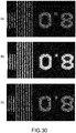
- Fig. 30 shows picked-up images obtained by picking up images of a resolution power chart of 625 line/mm and the generated composite image
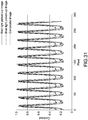
- Fig. 31 is a graph showing the contrast of each image. Note that the graph shown in Fig. 31 is normalized at the peak.
- Part (a) of Fig. 30 shows a picked-up image under the red illumination light (having a peak wavelength of 638 nm), and the contrast was 0.95.
- Part (b) of Fig. 30 shows a picked-up image under the blue illumination light (having a peak wavelength of 466 nm), and the contrast was 0.69.
- the contrast under the red illumination light is high in the frequency of 625 line/mm. Actually, the contrast under the red illumination light (0.95) was higher than the contrast under the blue illumination light (0.68).
- a composite image was generated with the method described in the second embodiment.
- the mask range was the reverse frequency (1000 line/mm).
- Part (c) of Fig. 30 shows the generated high-resolution image.
- the contrast of this image was 0.97, and was equivalent to the contrast of the picked-up image under the red illumination light (0.95).
- this resolution power chart (625 line/mm) is lower than the reverse frequency, it is found that the contrast of the picked-up image under the red illumination light is reflected on the composite image and a high contrast equivalent to the contrast of the picked-up image under the red illumination light is acquired.
- Fig. 32 shows picked-up images obtained by picking up images of a resolution power chart of 1250 line/mm and the generated composite image
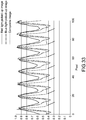
- Fig. 33 is a graph showing the contrast of each image. Note that the graph shown in Fig. 33 is normalized at the peak.
- Part (a) of Fig. 32 shows a picked-up image under the red illumination light (having a peak wavelength of 638 nm), and the contrast was 0.17.
- Part (b) of Fig. 32 shows a picked-up image under the blue illumination light (having a peak wavelength of 466 nm), and the contrast was 0.42.
- the contrast under the blue illumination light is high in the frequency of 1250 line/mm. Actually, the contrast under the blue illumination light (0.42) was higher than the contrast under the red illumination light (0.17) .
- a composite image was generated with the method described in the second embodiment.
- the mask range was the reverse frequency (1000 line/mm).
- Part (c) of Fig. 32 shows the generated high-resolution image.
- the contrast of this image was 0.38, and was equivalent to the contrast of the picked-up image under the blue illumination light (0.42).
- this resolution power chart (1250 line/mm) is higher than the reverse frequency, it is found that the contrast of the picked-up image under the blue illumination light is reflected on the high-resolution image and a high contrast equivalent to the contrast of the picked-up image under the blue illumination light is acquired.
- a pedestal in the contrast under the blue illumination light is removed in the contrast of the composite image (arrow in the figure), and artifact due to diffraction is alleviated.
- the composite image generated by the method according to the embodiment of the present technology has a contrast in a low frequency band equivalent to the contrast in a low frequency band under the illumination light in a long wavelength band (red light), and a contrast in a high frequency band equivalent to the contrast in a high frequency band under the illumination light in a short wavelength band (blue light). Specifically, the effects obtained by the embodiment of the present technology are verified.
Landscapes
- Engineering & Computer Science (AREA)
- Physics & Mathematics (AREA)
- Multimedia (AREA)
- General Physics & Mathematics (AREA)
- Theoretical Computer Science (AREA)
- Optics & Photonics (AREA)
- Analytical Chemistry (AREA)
- Chemical & Material Sciences (AREA)
- Signal Processing (AREA)
- Computing Systems (AREA)
- Computer Vision & Pattern Recognition (AREA)
- Microscoopes, Condenser (AREA)
- Image Processing (AREA)
- Studio Devices (AREA)
Claims (11)
- Bildverarbeitungsvorrichtung (130), umfassend:eine Bildumwandlungseinheit (131), die ein erstes aufgenommenes Bild und ein zweites aufgenommenes Bild in Frequenzkomponenten von jeweiligen Raumfrequenzbereichsbildern umwandelt, wobei das erste aufgenommene Bild durch Aufnehmen eines Bildes eines Beobachtungszielobjekts mit erstem Beleuchtungslicht über ein optisches Mikroskopsystem an einer ersten Fokalposition erhalten wird, wobei das zweite aufgenommene Bild durch Aufnehmen eines Bildes des Beobachtungszielobjekts mit zweitem Beleuchtungslicht über das optische Mikroskopsystem an einer zweiten Fokalposition erhalten wird, wobei das zweite aufgenommene Bild einen Kontrast in einem Niederfrequenzband, der niedriger als der des ersten aufgenommenen Bildes ist, und einen Kontrast in einem Hochfrequenzband, der höher als der des ersten aufgenommenen Bildes ist, aufweist; undeine Bilderzeugungseinheit (132), die eine Niederfrequenzkomponente des ersten aufgenommenen Bildes und eine Hochfrequenzkomponente des zweiten aufgenommenen Bildes miteinander kombiniert, um ein zusammengesetztes Bild zu erzeugen, wobeidas erste Beleuchtungslicht eine numerische Beleuchtungsapertur aufweist, die niedriger als die des zweiten Beleuchtungslichts ist.
- Bildverarbeitungsvorrichtung (130) nach Anspruch 1, wobei
das erste Beleuchtungslicht Schmalbandlicht in einem Wellenlängenband ist, das länger als das des zweiten Beleuchtungslichts ist, und
das zweite Beleuchtungslicht Schmalbandlicht in einem Wellenlängenband ist, das kürzer als das des ersten Beleuchtungslichts ist. - Bildverarbeitungsvorrichtung (130) nach Anspruch 2, wobei
das erste Beleuchtungslicht rotes Licht ist, und
das zweite Beleuchtungslicht blaues Licht ist. - Bildverarbeitungsvorrichtung (130) nach Anspruch 1, wobei
die Bildumwandlungseinheit (131) das erste aufgenommene Bild in ein Raumfrequenzbereichsbild umwandelt, um ein erstes Raumfrequenzbereichsbild zu erzeugen, und das zweite aufgenommene Bild in ein Raumfrequenzbereichsbild, um ein zweites Raumfrequenzbereichsbild zu erzeugen, und
die Bilderzeugungseinheit (132) das zusammengesetzte Bild aus einem Niederfrequenzbereich des ersten Raumfrequenzbereichsbildes und einem Hochfrequenzbereich des zweiten Raumfrequenzbereichsbildes erzeugt. - Bildverarbeitungsvorrichtung (130) nach Anspruch 4, wobei
die Bilderzeugungseinheit (132) ein kombiniertes Bild erzeugt, das durch Kombinieren des Niederfrequenzbereichs und des Hochfrequenzbereichs miteinander erhalten wird, und das zusammengesetzte Bild durch Umwandeln des kombinierten Bildes in ein Raumbereichsbild erzeugt. - Bildverarbeitungsvorrichtung (130) nach Anspruch 4, wobei
die Bilderzeugungseinheit (132) ein Niederfrequenzkomponentenbild, das durch Umwandeln des Niederfrequenzbereichs in ein Raumbereichsbild erhalten wird, und ein Hochfrequenzkomponentenbild, das durch Umwandeln des Hochfrequenzbereichs in ein Raumbereichsbild erhalten wird, erzeugt, und das zusammengesetzte Bild durch Addieren des Niederfrequenzkomponentenbildes und des Hochfrequenzkomponentenbildes miteinander erzeugt. - Mikroskopisches System, umfassend:die Bildverarbeitungsvorrichtung nach einem der Ansprüche 1 bis 6;eine Beleuchtungslampe, die das erste Beleuchtungslicht und das zweite Beleuchtungslicht zuführt;das optische Mikroskopsystem; undeine Abbildungseinheit.
- Mikroskopisches System nach Anspruch 7, ferner umfassend:einen Fokusanpassungsmechanismus, der eine Fokalposition des optischen Mikroskopsystems anpasst; undeine Steuereinheit, die den Fokusanpassungsmechanismus steuert, um zu bewirken, dass das optische Mikroskopsystem unter Bestrahlung des ersten Beleuchtungslichts auf das Beobachtungszielobjekt fokussiert, und zu bewirken, dass das optische Mikroskopsystem unter Bestrahlung des zweiten Beleuchtungslichts auf das Beobachtungszielobjekt fokussiert.
- Mikroskopisches System nach Anspruch 8, ferner umfassend:
eine Steuereinheit, die eine Lichtmenge des ersten Beleuchtungslichts und des zweiten Beleuchtungslichts so steuert, so dass eine Belichtung des ersten aufgenommenen Bildes und eine Belichtung des zweiten aufgenommenen Bildes übereinstimmen. - Bildverarbeitungsprogramm, das bewirkt, dass ein Computer funktioniert als:eine Bildumwandlungseinheit (131), die ein erstes aufgenommenes Bild und ein zweites aufgenommenes Bild in Frequenzkomponenten von jeweiligen Raumfrequenzbereichsbildern umwandelt, wobei das erste aufgenommene Bild durch Aufnehmen eines Bildes eines Beobachtungszielobjekts mit erstem Beleuchtungslicht über ein optisches Mikroskopsystem an einer ersten Fokalposition erhalten wird, wobei das zweite aufgenommene Bild durch Aufnehmen eines Bildes des Beobachtungszielobjekts mit zweitem Beleuchtungslicht über das optische Mikroskopsystem an einer zweiten Fokalposition erhalten wird, wobei das zweite aufgenommene Bild einen Kontrast in einem Niederfrequenzband, der niedriger als der des ersten aufgenommenen Bildes ist, und einen Kontrast in einem Hochfrequenzband, der höher als der des ersten aufgenommenen Bildes ist, aufweist; undeine Bilderzeugungseinheit (132), die eine Niederfrequenzkomponente des ersten aufgenommenen Bildes und eine Hochfrequenzkomponente des zweiten aufgenommenen Bildes miteinander kombiniert, um ein zusammengesetztes Bild zu erzeugen, wobeidas erste Beleuchtungslicht eine numerische Beleuchtungsapertur aufweist, die niedriger als die des zweiten Beleuchtungslichts ist.
- Computerimplementiertes Bildverarbeitungsverfahren, umfassend:Umwandeln eines ersten aufgenommenen Bildes und eines zweiten aufgenommenen Bildes durch eine Bildumwandlungseinheit (131) in Frequenzkomponenten von jeweiligen Raumfrequenzbereichsbildern, wobei das erste aufgenommene Bild durch Aufnehmen eines Bildes eines Beobachtungzielobjekts mit erstem Beleuchtungslicht über ein optisches Mikroskopsystem an einer ersten Fokalposition erhalten wird, wobei das zweite aufgenommene Bild durch Aufnehmen eines Bildes des Beobachtungszielobjekts mit zweitem Beleuchtungslicht über das optische Mikroskopsystem an einer zweiten Fokalposition erhalten wird, wobei das zweite aufgenommene Bild einen Kontrast in einem Niederfrequenzband, der niedriger als der des ersten aufgenommenen Bildes ist, und einen Kontrast in einem Hochfrequenzband, der höher als der des ersten aufgenommenen Bildes ist, aufweist; undKombinieren einer Niederfrequenzkomponente des ersten aufgenommenen Bildes und einer Hochfrequenzkomponente des zweiten aufgenommenen Bildes durch eine Bilderzeugungseinheit (132) miteinander, um ein zusammengesetztes Bild zu erzeugen, wobeidas erste Beleuchtungslicht eine numerische Beleuchtungsapertur aufweist, die niedriger als die des zweiten Beleuchtungslichts ist.
Applications Claiming Priority (2)
| Application Number | Priority Date | Filing Date | Title |
|---|---|---|---|
| JP2014100757A JP2015219282A (ja) | 2014-05-14 | 2014-05-14 | 画像処理装置、画像処理プログラム、画像処理方法及び顕微鏡システム |
| PCT/JP2015/002009 WO2015174011A1 (ja) | 2014-05-14 | 2015-04-09 | 画像処理装置、画像処理プログラム、画像処理方法及び顕微鏡システム |
Publications (3)
| Publication Number | Publication Date |
|---|---|
| EP3144712A1 EP3144712A1 (de) | 2017-03-22 |
| EP3144712A4 EP3144712A4 (de) | 2018-01-17 |
| EP3144712B1 true EP3144712B1 (de) | 2021-06-02 |
Family
ID=54479566
Family Applications (1)
| Application Number | Title | Priority Date | Filing Date |
|---|---|---|---|
| EP15792978.7A Active EP3144712B1 (de) | 2014-05-14 | 2015-04-09 | Bildbearbeitungsvorrichtung, bildbearbeitungsprogramm, bildbearbeitungsverfahren und mikroskopsystem |
Country Status (4)
| Country | Link |
|---|---|
| US (1) | US10200604B2 (de) |
| EP (1) | EP3144712B1 (de) |
| JP (1) | JP2015219282A (de) |
| WO (1) | WO2015174011A1 (de) |
Families Citing this family (9)
| Publication number | Priority date | Publication date | Assignee | Title |
|---|---|---|---|---|
| JP6817566B2 (ja) * | 2016-07-22 | 2021-01-20 | パナソニックIpマネジメント株式会社 | 画像生成装置及び画像生成方法 |
| KR101853658B1 (ko) * | 2016-09-29 | 2018-05-03 | 주식회사 싸이토젠 | 세포 이미지 스티칭 중 고해상도 구현방법 |
| CN113454511B (zh) * | 2018-12-21 | 2023-11-14 | 斯科皮奥实验室有限公司 | 显微图像的压缩获取 |
| WO2021014682A1 (ja) * | 2019-07-19 | 2021-01-28 | 株式会社日立ハイテク | 粒子定量装置 |
| US12326391B2 (en) * | 2019-07-29 | 2025-06-10 | Hitachi High-Tech Corporation | Particle quantifying device |
| DE102020113313A1 (de) * | 2020-05-15 | 2021-11-18 | Carl Zeiss Microscopy Gmbh | Verfahren, computerprogramm und mikroskopsystem zum verarbeiten von mikroskopbildern |
| US12236624B2 (en) * | 2020-09-23 | 2025-02-25 | Smith & Nephew, Inc. | Optical caliper for 3-D endoscopic imaging and measurement |
| JP7677197B2 (ja) | 2022-03-18 | 2025-05-15 | カシオ計算機株式会社 | 撮像装置、撮像制御方法およびプログラム |
| CN114936994B (zh) * | 2022-05-19 | 2024-09-17 | 中国人民解放军总医院第一医学中心 | 一种显微手术中的多景深拍照融合方法及系统 |
Family Cites Families (9)
| Publication number | Priority date | Publication date | Assignee | Title |
|---|---|---|---|---|
| JP2883648B2 (ja) | 1988-10-03 | 1999-04-19 | オリンパス光学工業株式会社 | 画像入出力装置 |
| DE3931934C2 (de) | 1988-10-03 | 1994-11-10 | Olympus Optical Co | Bild-Ein/Ausgabevorrichtung |
| US20060093234A1 (en) * | 2004-11-04 | 2006-05-04 | Silverstein D A | Reduction of blur in multi-channel images |
| JP4814840B2 (ja) | 2007-05-23 | 2011-11-16 | オリンパス株式会社 | 画像処理装置又は画像処理プログラム |
| CN101889453B (zh) * | 2008-06-18 | 2013-11-13 | 松下电器产业株式会社 | 图像处理装置、摄像装置、方法及程序 |
| JP5582935B2 (ja) * | 2010-09-22 | 2014-09-03 | 富士フイルム株式会社 | 撮像モジュール |
| JP5761458B2 (ja) * | 2012-06-05 | 2015-08-12 | 株式会社ニコン | 顕微鏡装置 |
| JP5347051B2 (ja) | 2012-06-26 | 2013-11-20 | 株式会社キーエンス | 拡大観察装置、拡大観察方法及び拡大観察プログラム |
| US9064304B2 (en) * | 2013-03-18 | 2015-06-23 | General Electric Company | Image quality assessment of microscopy images |
-
2014
- 2014-05-14 JP JP2014100757A patent/JP2015219282A/ja active Pending
-
2015
- 2015-04-09 WO PCT/JP2015/002009 patent/WO2015174011A1/ja not_active Ceased
- 2015-04-09 US US15/309,230 patent/US10200604B2/en active Active
- 2015-04-09 EP EP15792978.7A patent/EP3144712B1/de active Active
Non-Patent Citations (1)
| Title |
|---|
| None * |
Also Published As
| Publication number | Publication date |
|---|---|
| US10200604B2 (en) | 2019-02-05 |
| EP3144712A1 (de) | 2017-03-22 |
| US20170085789A1 (en) | 2017-03-23 |
| WO2015174011A1 (ja) | 2015-11-19 |
| JP2015219282A (ja) | 2015-12-07 |
| EP3144712A4 (de) | 2018-01-17 |
Similar Documents
| Publication | Publication Date | Title |
|---|---|---|
| EP3144712B1 (de) | Bildbearbeitungsvorrichtung, bildbearbeitungsprogramm, bildbearbeitungsverfahren und mikroskopsystem | |
| US10838192B2 (en) | Method and device for high-resolution color imaging using merged images from holographic and lens-based devices | |
| JP5188651B2 (ja) | 画像処理装置、およびそれを用いた撮像装置 | |
| JP5284537B2 (ja) | 画像処理装置、画像処理方法、画像処理プログラム、およびそれを用いた撮像装置 | |
| CN104956661B (zh) | 图像拾取装置、图像处理装置、图像处理方法 | |
| Zhang et al. | Color calibration and fusion of lens-free and mobile-phone microscopy images for high-resolution and accurate color reproduction | |
| US8659672B2 (en) | Image processing apparatus and image pickup apparatus using same | |
| WO2013038628A1 (en) | Image processing method, image processing apparatus and image pickup apparatus | |
| US20130120614A1 (en) | Image processing device, imaging device, and image processing method | |
| JP5344648B2 (ja) | 画像処理方法、画像処理装置、撮像装置および画像処理プログラム | |
| WO2017163427A1 (ja) | 顕微鏡観察システム、顕微鏡観察方法、及び顕微鏡観察プログラム | |
| WO2024015012A1 (en) | Optical system and method of forming the same, method of forming a multi-color image | |
| US9229211B2 (en) | Imaging apparatus, imaging control program, and imaging method | |
| JP2014150423A (ja) | 撮像装置、画像処理装置、画像処理方法、画像処理プログラム、および、記憶媒体 | |
| WO2015098243A1 (ja) | 画像処理装置、撮像装置、プログラム及び画像処理方法 | |
| JP5645981B2 (ja) | 撮像装置、画像処理装置、画像処理方法、画像処理プログラム、および、記憶媒体 | |
| JP2017050662A (ja) | 画像処理装置、撮像装置および画像処理プログラム | |
| JP2019071596A (ja) | 撮像装置およびその制御方法 | |
| JP2014202673A (ja) | マルチバンド撮像装置およびその制御方法 | |
| JP2018067868A (ja) | 撮像装置 | |
| JP2009047735A (ja) | 撮像装置及び画像処理プログラム | |
| JP7790941B2 (ja) | 撮像装置及びそれを制御する制御方法およびプログラム、光学装置 | |
| JP7790940B2 (ja) | 撮像装置及びそれを制御する制御方法およびプログラム、光学装置 | |
| JP6552375B2 (ja) | 画像処理装置、撮像装置および画像処理プログラム | |
| JP2015091072A (ja) | 撮像装置及びこの撮像装置を備えた撮像システム及び偽色除去方法 |
Legal Events
| Date | Code | Title | Description |
|---|---|---|---|
| STAA | Information on the status of an ep patent application or granted ep patent |
Free format text: STATUS: THE INTERNATIONAL PUBLICATION HAS BEEN MADE |
|
| PUAI | Public reference made under article 153(3) epc to a published international application that has entered the european phase |
Free format text: ORIGINAL CODE: 0009012 |
|
| STAA | Information on the status of an ep patent application or granted ep patent |
Free format text: STATUS: REQUEST FOR EXAMINATION WAS MADE |
|
| 17P | Request for examination filed |
Effective date: 20161107 |
|
| AK | Designated contracting states |
Kind code of ref document: A1 Designated state(s): AL AT BE BG CH CY CZ DE DK EE ES FI FR GB GR HR HU IE IS IT LI LT LU LV MC MK MT NL NO PL PT RO RS SE SI SK SM TR |
|
| AX | Request for extension of the european patent |
Extension state: BA ME |
|
| DAV | Request for validation of the european patent (deleted) | ||
| DAX | Request for extension of the european patent (deleted) | ||
| A4 | Supplementary search report drawn up and despatched |
Effective date: 20171215 |
|
| RIC1 | Information provided on ipc code assigned before grant |
Ipc: G02B 21/36 20060101AFI20171211BHEP Ipc: G06T 5/00 20060101ALI20171211BHEP Ipc: G06T 5/50 20060101ALI20171211BHEP Ipc: H04N 5/232 20060101ALI20171211BHEP Ipc: G06T 3/00 20060101ALI20171211BHEP Ipc: H04N 5/225 20060101ALI20171211BHEP Ipc: G02B 21/06 20060101ALI20171211BHEP |
|
| STAA | Information on the status of an ep patent application or granted ep patent |
Free format text: STATUS: EXAMINATION IS IN PROGRESS |
|
| 17Q | First examination report despatched |
Effective date: 20191114 |
|
| GRAP | Despatch of communication of intention to grant a patent |
Free format text: ORIGINAL CODE: EPIDOSNIGR1 |
|
| STAA | Information on the status of an ep patent application or granted ep patent |
Free format text: STATUS: GRANT OF PATENT IS INTENDED |
|
| INTG | Intention to grant announced |
Effective date: 20201201 |
|
| GRAS | Grant fee paid |
Free format text: ORIGINAL CODE: EPIDOSNIGR3 |
|
| GRAA | (expected) grant |
Free format text: ORIGINAL CODE: 0009210 |
|
| STAA | Information on the status of an ep patent application or granted ep patent |
Free format text: STATUS: THE PATENT HAS BEEN GRANTED |
|
| REG | Reference to a national code |
Ref country code: CH Ref legal event code: EP |
|
| AK | Designated contracting states |
Kind code of ref document: B1 Designated state(s): AL AT BE BG CH CY CZ DE DK EE ES FI FR GB GR HR HU IE IS IT LI LT LU LV MC MK MT NL NO PL PT RO RS SE SI SK SM TR |
|
| REG | Reference to a national code |
Ref country code: GB Ref legal event code: FG4D |
|
| REG | Reference to a national code |
Ref country code: AT Ref legal event code: REF Ref document number: 1399002 Country of ref document: AT Kind code of ref document: T Effective date: 20210615 |
|
| REG | Reference to a national code |
Ref country code: IE Ref legal event code: FG4D |
|
| REG | Reference to a national code |
Ref country code: DE Ref legal event code: R096 Ref document number: 602015070042 Country of ref document: DE |
|
| RAP4 | Party data changed (patent owner data changed or rights of a patent transferred) |
Owner name: SONY GROUP CORPORATION |
|
| REG | Reference to a national code |
Ref country code: LT Ref legal event code: MG9D |
|
| PG25 | Lapsed in a contracting state [announced via postgrant information from national office to epo] |
Ref country code: FI Free format text: LAPSE BECAUSE OF FAILURE TO SUBMIT A TRANSLATION OF THE DESCRIPTION OR TO PAY THE FEE WITHIN THE PRESCRIBED TIME-LIMIT Effective date: 20210602 Ref country code: LT Free format text: LAPSE BECAUSE OF FAILURE TO SUBMIT A TRANSLATION OF THE DESCRIPTION OR TO PAY THE FEE WITHIN THE PRESCRIBED TIME-LIMIT Effective date: 20210602 Ref country code: HR Free format text: LAPSE BECAUSE OF FAILURE TO SUBMIT A TRANSLATION OF THE DESCRIPTION OR TO PAY THE FEE WITHIN THE PRESCRIBED TIME-LIMIT Effective date: 20210602 Ref country code: BG Free format text: LAPSE BECAUSE OF FAILURE TO SUBMIT A TRANSLATION OF THE DESCRIPTION OR TO PAY THE FEE WITHIN THE PRESCRIBED TIME-LIMIT Effective date: 20210902 |
|
| REG | Reference to a national code |
Ref country code: NL Ref legal event code: MP Effective date: 20210602 |
|
| REG | Reference to a national code |
Ref country code: AT Ref legal event code: MK05 Ref document number: 1399002 Country of ref document: AT Kind code of ref document: T Effective date: 20210602 |
|
| PG25 | Lapsed in a contracting state [announced via postgrant information from national office to epo] |
Ref country code: LV Free format text: LAPSE BECAUSE OF FAILURE TO SUBMIT A TRANSLATION OF THE DESCRIPTION OR TO PAY THE FEE WITHIN THE PRESCRIBED TIME-LIMIT Effective date: 20210602 Ref country code: GR Free format text: LAPSE BECAUSE OF FAILURE TO SUBMIT A TRANSLATION OF THE DESCRIPTION OR TO PAY THE FEE WITHIN THE PRESCRIBED TIME-LIMIT Effective date: 20210903 Ref country code: PL Free format text: LAPSE BECAUSE OF FAILURE TO SUBMIT A TRANSLATION OF THE DESCRIPTION OR TO PAY THE FEE WITHIN THE PRESCRIBED TIME-LIMIT Effective date: 20210602 Ref country code: NO Free format text: LAPSE BECAUSE OF FAILURE TO SUBMIT A TRANSLATION OF THE DESCRIPTION OR TO PAY THE FEE WITHIN THE PRESCRIBED TIME-LIMIT Effective date: 20210902 Ref country code: RS Free format text: LAPSE BECAUSE OF FAILURE TO SUBMIT A TRANSLATION OF THE DESCRIPTION OR TO PAY THE FEE WITHIN THE PRESCRIBED TIME-LIMIT Effective date: 20210602 Ref country code: SE Free format text: LAPSE BECAUSE OF FAILURE TO SUBMIT A TRANSLATION OF THE DESCRIPTION OR TO PAY THE FEE WITHIN THE PRESCRIBED TIME-LIMIT Effective date: 20210602 |
|
| PG25 | Lapsed in a contracting state [announced via postgrant information from national office to epo] |
Ref country code: EE Free format text: LAPSE BECAUSE OF FAILURE TO SUBMIT A TRANSLATION OF THE DESCRIPTION OR TO PAY THE FEE WITHIN THE PRESCRIBED TIME-LIMIT Effective date: 20210602 Ref country code: CZ Free format text: LAPSE BECAUSE OF FAILURE TO SUBMIT A TRANSLATION OF THE DESCRIPTION OR TO PAY THE FEE WITHIN THE PRESCRIBED TIME-LIMIT Effective date: 20210602 Ref country code: SK Free format text: LAPSE BECAUSE OF FAILURE TO SUBMIT A TRANSLATION OF THE DESCRIPTION OR TO PAY THE FEE WITHIN THE PRESCRIBED TIME-LIMIT Effective date: 20210602 Ref country code: SM Free format text: LAPSE BECAUSE OF FAILURE TO SUBMIT A TRANSLATION OF THE DESCRIPTION OR TO PAY THE FEE WITHIN THE PRESCRIBED TIME-LIMIT Effective date: 20210602 Ref country code: ES Free format text: LAPSE BECAUSE OF FAILURE TO SUBMIT A TRANSLATION OF THE DESCRIPTION OR TO PAY THE FEE WITHIN THE PRESCRIBED TIME-LIMIT Effective date: 20210602 Ref country code: NL Free format text: LAPSE BECAUSE OF FAILURE TO SUBMIT A TRANSLATION OF THE DESCRIPTION OR TO PAY THE FEE WITHIN THE PRESCRIBED TIME-LIMIT Effective date: 20210602 Ref country code: PT Free format text: LAPSE BECAUSE OF FAILURE TO SUBMIT A TRANSLATION OF THE DESCRIPTION OR TO PAY THE FEE WITHIN THE PRESCRIBED TIME-LIMIT Effective date: 20211004 Ref country code: RO Free format text: LAPSE BECAUSE OF FAILURE TO SUBMIT A TRANSLATION OF THE DESCRIPTION OR TO PAY THE FEE WITHIN THE PRESCRIBED TIME-LIMIT Effective date: 20210602 Ref country code: AT Free format text: LAPSE BECAUSE OF FAILURE TO SUBMIT A TRANSLATION OF THE DESCRIPTION OR TO PAY THE FEE WITHIN THE PRESCRIBED TIME-LIMIT Effective date: 20210602 |
|
| REG | Reference to a national code |
Ref country code: DE Ref legal event code: R097 Ref document number: 602015070042 Country of ref document: DE |
|
| PLBE | No opposition filed within time limit |
Free format text: ORIGINAL CODE: 0009261 |
|
| STAA | Information on the status of an ep patent application or granted ep patent |
Free format text: STATUS: NO OPPOSITION FILED WITHIN TIME LIMIT |
|
| PG25 | Lapsed in a contracting state [announced via postgrant information from national office to epo] |
Ref country code: DK Free format text: LAPSE BECAUSE OF FAILURE TO SUBMIT A TRANSLATION OF THE DESCRIPTION OR TO PAY THE FEE WITHIN THE PRESCRIBED TIME-LIMIT Effective date: 20210602 |
|
| 26N | No opposition filed |
Effective date: 20220303 |
|
| PG25 | Lapsed in a contracting state [announced via postgrant information from national office to epo] |
Ref country code: AL Free format text: LAPSE BECAUSE OF FAILURE TO SUBMIT A TRANSLATION OF THE DESCRIPTION OR TO PAY THE FEE WITHIN THE PRESCRIBED TIME-LIMIT Effective date: 20210602 |
|
| PG25 | Lapsed in a contracting state [announced via postgrant information from national office to epo] |
Ref country code: IT Free format text: LAPSE BECAUSE OF FAILURE TO SUBMIT A TRANSLATION OF THE DESCRIPTION OR TO PAY THE FEE WITHIN THE PRESCRIBED TIME-LIMIT Effective date: 20210602 |
|
| REG | Reference to a national code |
Ref country code: CH Ref legal event code: PL |
|
| GBPC | Gb: european patent ceased through non-payment of renewal fee |
Effective date: 20220409 |
|
| REG | Reference to a national code |
Ref country code: BE Ref legal event code: MM Effective date: 20220430 |
|
| PG25 | Lapsed in a contracting state [announced via postgrant information from national office to epo] |
Ref country code: MC Free format text: LAPSE BECAUSE OF FAILURE TO SUBMIT A TRANSLATION OF THE DESCRIPTION OR TO PAY THE FEE WITHIN THE PRESCRIBED TIME-LIMIT Effective date: 20210602 Ref country code: LU Free format text: LAPSE BECAUSE OF NON-PAYMENT OF DUE FEES Effective date: 20220409 Ref country code: LI Free format text: LAPSE BECAUSE OF NON-PAYMENT OF DUE FEES Effective date: 20220430 Ref country code: GB Free format text: LAPSE BECAUSE OF NON-PAYMENT OF DUE FEES Effective date: 20220409 Ref country code: FR Free format text: LAPSE BECAUSE OF NON-PAYMENT OF DUE FEES Effective date: 20220430 Ref country code: CH Free format text: LAPSE BECAUSE OF NON-PAYMENT OF DUE FEES Effective date: 20220430 |
|
| PG25 | Lapsed in a contracting state [announced via postgrant information from national office to epo] |
Ref country code: BE Free format text: LAPSE BECAUSE OF NON-PAYMENT OF DUE FEES Effective date: 20220430 |
|
| PG25 | Lapsed in a contracting state [announced via postgrant information from national office to epo] |
Ref country code: IE Free format text: LAPSE BECAUSE OF NON-PAYMENT OF DUE FEES Effective date: 20220409 |
|
| P01 | Opt-out of the competence of the unified patent court (upc) registered |
Effective date: 20230527 |
|
| PGFP | Annual fee paid to national office [announced via postgrant information from national office to epo] |
Ref country code: DE Payment date: 20230321 Year of fee payment: 9 |
|
| PG25 | Lapsed in a contracting state [announced via postgrant information from national office to epo] |
Ref country code: HU Free format text: LAPSE BECAUSE OF FAILURE TO SUBMIT A TRANSLATION OF THE DESCRIPTION OR TO PAY THE FEE WITHIN THE PRESCRIBED TIME-LIMIT; INVALID AB INITIO Effective date: 20150409 |
|
| PG25 | Lapsed in a contracting state [announced via postgrant information from national office to epo] |
Ref country code: MK Free format text: LAPSE BECAUSE OF FAILURE TO SUBMIT A TRANSLATION OF THE DESCRIPTION OR TO PAY THE FEE WITHIN THE PRESCRIBED TIME-LIMIT Effective date: 20210602 Ref country code: CY Free format text: LAPSE BECAUSE OF FAILURE TO SUBMIT A TRANSLATION OF THE DESCRIPTION OR TO PAY THE FEE WITHIN THE PRESCRIBED TIME-LIMIT Effective date: 20210602 |
|
| PG25 | Lapsed in a contracting state [announced via postgrant information from national office to epo] |
Ref country code: TR Free format text: LAPSE BECAUSE OF FAILURE TO SUBMIT A TRANSLATION OF THE DESCRIPTION OR TO PAY THE FEE WITHIN THE PRESCRIBED TIME-LIMIT Effective date: 20210602 |
|
| PG25 | Lapsed in a contracting state [announced via postgrant information from national office to epo] |
Ref country code: MT Free format text: LAPSE BECAUSE OF FAILURE TO SUBMIT A TRANSLATION OF THE DESCRIPTION OR TO PAY THE FEE WITHIN THE PRESCRIBED TIME-LIMIT Effective date: 20210602 |
|
| REG | Reference to a national code |
Ref country code: DE Ref legal event code: R119 Ref document number: 602015070042 Country of ref document: DE |
|
| PG25 | Lapsed in a contracting state [announced via postgrant information from national office to epo] |
Ref country code: DE Free format text: LAPSE BECAUSE OF NON-PAYMENT OF DUE FEES Effective date: 20241105 |
|
| PG25 | Lapsed in a contracting state [announced via postgrant information from national office to epo] |
Ref country code: DE Free format text: LAPSE BECAUSE OF NON-PAYMENT OF DUE FEES Effective date: 20241105 |