EP3144715A1 - Procédé de compensation d'aberrations optiques à l'aide d'un miroir déformable - Google Patents
Procédé de compensation d'aberrations optiques à l'aide d'un miroir déformable Download PDFInfo
- Publication number
- EP3144715A1 EP3144715A1 EP16187416.9A EP16187416A EP3144715A1 EP 3144715 A1 EP3144715 A1 EP 3144715A1 EP 16187416 A EP16187416 A EP 16187416A EP 3144715 A1 EP3144715 A1 EP 3144715A1
- Authority
- EP
- European Patent Office
- Prior art keywords
- mirror
- matrix
- displacements
- deformable mirror
- forces
- Prior art date
- Legal status (The legal status is an assumption and is not a legal conclusion. Google has not performed a legal analysis and makes no representation as to the accuracy of the status listed.)
- Withdrawn
Links
- 230000004075 alteration Effects 0.000 title claims abstract description 49
- 230000003287 optical effect Effects 0.000 title claims abstract description 44
- 238000000034 method Methods 0.000 title claims abstract description 22
- 238000006073 displacement reaction Methods 0.000 claims abstract description 48
- 239000011159 matrix material Substances 0.000 claims abstract description 48
- 238000005259 measurement Methods 0.000 claims abstract description 10
- 230000015572 biosynthetic process Effects 0.000 claims abstract description 8
- 230000009471 action Effects 0.000 claims abstract description 5
- 230000035945 sensitivity Effects 0.000 description 4
- 238000004458 analytical method Methods 0.000 description 3
- 230000000694 effects Effects 0.000 description 3
- 230000005484 gravity Effects 0.000 description 2
- 229910001374 Invar Inorganic materials 0.000 description 1
- 230000003044 adaptive effect Effects 0.000 description 1
- 238000012937 correction Methods 0.000 description 1
- 238000000354 decomposition reaction Methods 0.000 description 1
- 238000011156 evaluation Methods 0.000 description 1
- 239000002241 glass-ceramic Substances 0.000 description 1
- 238000004519 manufacturing process Methods 0.000 description 1
- 230000007246 mechanism Effects 0.000 description 1
- 230000004048 modification Effects 0.000 description 1
- 238000012986 modification Methods 0.000 description 1
- 230000009466 transformation Effects 0.000 description 1
- 230000017105 transposition Effects 0.000 description 1
Images



Classifications
-
- G—PHYSICS
- G02—OPTICS
- G02B—OPTICAL ELEMENTS, SYSTEMS OR APPARATUS
- G02B27/00—Optical systems or apparatus not provided for by any of the groups G02B1/00 - G02B26/00, G02B30/00
- G02B27/0025—Optical systems or apparatus not provided for by any of the groups G02B1/00 - G02B26/00, G02B30/00 for optical correction, e.g. distorsion, aberration
- G02B27/0068—Optical systems or apparatus not provided for by any of the groups G02B1/00 - G02B26/00, G02B30/00 for optical correction, e.g. distorsion, aberration having means for controlling the degree of correction, e.g. using phase modulators, movable elements
-
- G—PHYSICS
- G02—OPTICS
- G02B—OPTICAL ELEMENTS, SYSTEMS OR APPARATUS
- G02B26/00—Optical devices or arrangements for the control of light using movable or deformable optical elements
- G02B26/08—Optical devices or arrangements for the control of light using movable or deformable optical elements for controlling the direction of light
- G02B26/0816—Optical devices or arrangements for the control of light using movable or deformable optical elements for controlling the direction of light by means of one or more reflecting elements
- G02B26/0825—Optical devices or arrangements for the control of light using movable or deformable optical elements for controlling the direction of light by means of one or more reflecting elements the reflecting element being a flexible sheet or membrane, e.g. for varying the focus
-
- G—PHYSICS
- G02—OPTICS
- G02B—OPTICAL ELEMENTS, SYSTEMS OR APPARATUS
- G02B26/00—Optical devices or arrangements for the control of light using movable or deformable optical elements
- G02B26/06—Optical devices or arrangements for the control of light using movable or deformable optical elements for controlling the phase of light
-
- G—PHYSICS
- G02—OPTICS
- G02B—OPTICAL ELEMENTS, SYSTEMS OR APPARATUS
- G02B27/00—Optical systems or apparatus not provided for by any of the groups G02B1/00 - G02B26/00, G02B30/00
- G02B27/0025—Optical systems or apparatus not provided for by any of the groups G02B1/00 - G02B26/00, G02B30/00 for optical correction, e.g. distorsion, aberration
-
- G—PHYSICS
- G02—OPTICS
- G02B—OPTICAL ELEMENTS, SYSTEMS OR APPARATUS
- G02B7/00—Mountings, adjusting means, or light-tight connections, for optical elements
- G02B7/18—Mountings, adjusting means, or light-tight connections, for optical elements for prisms; for mirrors
- G02B7/181—Mountings, adjusting means, or light-tight connections, for optical elements for prisms; for mirrors with means for compensating for changes in temperature or for controlling the temperature; thermal stabilisation
Definitions
- the present invention relates to methods providing for compensation of optical aberrations and more particularly to methods providing for compensation of optical aberrations with the use of a deformable mirror, which can find use in active optical systems devised for correcting aberrations of the wavefront of light beams.
- Active optics enable modification of the wavefront shape for compensating aberrations due to, for example, thermal distortion of optical elements, optical part manufacturing and mounting errors, the gravity action or the absence of gravity in the space that distorts the results of an adjustment on the ground.
- Zernike polynomials are the most often used ( Active Optics Correction Of Thermal Distortion Of A 1.8 Meter Mirror / E. Pearson, L. Stepp, J. Fox // Optical Engineering, 27(2), 115-122 (Feb 01, 1988 ). Axial displacements of the mirror reflective surface arising during mirror deformation are represented as the superposition of Zernike polynomials.
- a drawback of the above-mentioned method is a limited compensation accuracy of the wavefront aberrations. It is due to the fact that the Zernike polynomials describe displacements of optical surfaces, while the strain state of a mirror is three-dimensional. That is why it is impossible to provide the superposition of the Zernike polynomials on the reflective surface of the deformable mirror to compensate the wavefront aberrations exactly.
- this method can improve the compensation accuracy in comparison with the method using the Zernike polynomials, but only in part, since the natural frequency modes of the mirror vibrations used by the method do not correspond to the orthogonal modes of the mirror deformation in the conditions of quasi-static loading implemented in active optical systems.
- the last phenomenon is explained by the fact that the natural frequency modes of the mirror depend on the real distribution of the mass in the volume of the mirror structure, while in the case of the quasi-static loading, the inertia-mass characteristics have no effect on the displacements induced by force actuators.
- the technical result of the present invention is to improve the accuracy of compensation of the light beam wavefront aberrations in active optical systems.
- the present invention implements the fact that the quasi-static loading of a real deformable mirror in an active optical system is entirely described by the superposition of orthogonal natural frequency modes of the mirror simulator, where the number of modes is equal to the number of acting forces or displacements exerted with force actuators.
- the number of modes is equal to the number of acting forces or displacements exerted with force actuators.
- the method for compensating optical aberrations of the present application is carried out as follows:
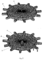
- a mirror was considered having the structure in the shape of a vase, the finite-element model of which is shown in Fig. 2 .
- the mirror is assembled: a central boss 1 and a ring with arms 2, made of invar are glued to a disk with the optical surface 3, made of glass ceramic.
- the central boss is fixedly attached.
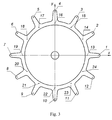
- the mirror is loaded by 24 axial forces provided by force actuators. Holes for attaching mechanisms, arranged in pairs on 12 arms are illustrated by arrows in Fig. 2 . Numeration of places of attachment is given in Fig. 3 .
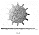
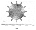
- the contour lines of axial displacements of the deformable mirror optical surface for first, 14th and 18th natural frequency modes of the mirror simulator vibrations are given in Figs. 4-6 , respectively.
- the natural frequency for the mode 1 is 30.3852 Hz
- for the mode 14 is 485.583 Hz
- for the mode 18 is 757.419 Hz.
- the Figures show that the natural modes represent the particularities of the geometric shape of the mirror: the presence of a central boss and the location of arms.
- Table 1 illustrates the elements of the first column of the matrix M - 1 for cases of assigning displacements and forces to force actuators.
- the needed 24 natural frequency modes of the mirror simulator vibrations for axial displacements of the optical surface multiplied by respective coefficients are represented by their root-mean-square values in the second column of Table 2.
- Table 3 gives the forces found in accordance with the relationship (3).
- the finite-element method was used to calculate the displacements of the real mirror optical surface nodes under the effect of forces found, and to approximate them by natural frequency modes of the imitator.
- Fig. 7 shows nodes of a finite-element grid on the mirror optical surface used for approximation with natural modes. The error of approximation is within machine precision. It means that no additional displacements appeared on the reflective surface that could distort the displacements assigned.
- the results of the finite-element method calculations are given in the third column of Table 2. As we see, the prescribed superposition of the natural frequency modes of the mirror simulator vibrations on a controlled deformable mirror with an error that is within machine precision.
- the given example confirms that the superposition of orthogonal natural frequency modes of the mirror simulator vibrations entirely describes the quasi-static loading of a real deformable mirror under the effect of force actuators. So, the method of the present application enables to eliminate the part of the error of compensation of the active optical system aberrations that is related to the formation of the superposition of modes on the reflective surface of the deformable mirror, needed to compensate wavefront aberrations.
Landscapes
- Physics & Mathematics (AREA)
- General Physics & Mathematics (AREA)
- Optics & Photonics (AREA)
- Optical Elements Other Than Lenses (AREA)
- Mechanical Light Control Or Optical Switches (AREA)
Applications Claiming Priority (1)
| Application Number | Priority Date | Filing Date | Title |
|---|---|---|---|
| RU2015139306A RU2623661C2 (ru) | 2015-09-15 | 2015-09-15 | Способ компенсации оптических аберраций с использованием деформируемого зеркала |
Publications (1)
| Publication Number | Publication Date |
|---|---|
| EP3144715A1 true EP3144715A1 (fr) | 2017-03-22 |
Family
ID=56876980
Family Applications (1)
| Application Number | Title | Priority Date | Filing Date |
|---|---|---|---|
| EP16187416.9A Withdrawn EP3144715A1 (fr) | 2015-09-15 | 2016-09-06 | Procédé de compensation d'aberrations optiques à l'aide d'un miroir déformable |
Country Status (3)
| Country | Link |
|---|---|
| US (1) | US9804388B2 (fr) |
| EP (1) | EP3144715A1 (fr) |
| RU (1) | RU2623661C2 (fr) |
Cited By (1)
| Publication number | Priority date | Publication date | Assignee | Title |
|---|---|---|---|---|
| CN110095858A (zh) * | 2018-12-12 | 2019-08-06 | 中国科学院紫金山天文台 | 自适应光学变形镜弹性模态像差表征方法 |
Families Citing this family (5)
| Publication number | Priority date | Publication date | Assignee | Title |
|---|---|---|---|---|
| RU2698635C2 (ru) * | 2017-12-14 | 2019-08-28 | федеральное государственное бюджетное образовательное учреждение высшего образования "Самарский государственный технический университет" | Способ модального управления квазистатическими линейно-упругими перемещениями конструкции |
| CN110007457B (zh) * | 2018-11-22 | 2021-05-18 | 北京航天计量测试技术研究所 | 一种控制变形像差的光学设计方法 |
| FR3100344B1 (fr) * | 2019-08-30 | 2021-09-24 | Alpao | Dispositif d’optique adaptative de construction simplifiee et procede de fabrication associe |
| CN110795872A (zh) * | 2019-09-30 | 2020-02-14 | 扬州尼尔液压科技有限公司 | 基于Ansys薄膜变形的液体变焦镜片的光学仿真方法 |
| CN115453750B (zh) * | 2022-08-30 | 2024-03-01 | 中国科学院长春光学精密机械与物理研究所 | 拼接式反射镜的面形精度分析方法、装置、设备 |
Citations (3)
| Publication number | Priority date | Publication date | Assignee | Title |
|---|---|---|---|---|
| US4993823A (en) * | 1989-06-29 | 1991-02-19 | Eastman Kodak Company | Method for correction of distortions of an imaging device |
| EP0802438A2 (fr) * | 1996-04-18 | 1997-10-22 | Mitsubishi Denki Kabushiki Kaisha | Appareil de contrÔle de la forme pour miroirs réflecteurs |
| US8102583B2 (en) | 2009-03-26 | 2012-01-24 | Raytheon Company | Real-time optical compensation of orbit-induced distortion effects in long integration time imagers |
Family Cites Families (6)
| Publication number | Priority date | Publication date | Assignee | Title |
|---|---|---|---|---|
| US5745309A (en) * | 1994-06-13 | 1998-04-28 | The United States Of America As Represented By The United States Department Of Energy | Method for removing tilt control in adaptive optics systems |
| WO2002101442A1 (fr) * | 2001-06-12 | 2002-12-19 | California Institute Of Technology | Miroir deformable a membrane continue unimorphe a base de pzt, |
| US6880942B2 (en) * | 2002-06-20 | 2005-04-19 | Nikon Corporation | Adaptive optic with discrete actuators for continuous deformation of a deformable mirror system |
| JP4920461B2 (ja) * | 2007-03-14 | 2012-04-18 | 株式会社トプコン | 波面収差補正装置 |
| US9383576B2 (en) * | 2012-07-17 | 2016-07-05 | Rachel Andreasen | Apparatus and method for a flexible adaptive telescope mirror |
| CN104133291A (zh) * | 2014-03-17 | 2014-11-05 | 电子科技大学 | 多层自适应光学中放大变形镜位移冲程的变形镜匹配方式 |
-
2015
- 2015-09-15 RU RU2015139306A patent/RU2623661C2/ru not_active IP Right Cessation
-
2016
- 2016-09-06 EP EP16187416.9A patent/EP3144715A1/fr not_active Withdrawn
- 2016-09-15 US US15/267,011 patent/US9804388B2/en not_active Expired - Fee Related
Patent Citations (3)
| Publication number | Priority date | Publication date | Assignee | Title |
|---|---|---|---|---|
| US4993823A (en) * | 1989-06-29 | 1991-02-19 | Eastman Kodak Company | Method for correction of distortions of an imaging device |
| EP0802438A2 (fr) * | 1996-04-18 | 1997-10-22 | Mitsubishi Denki Kabushiki Kaisha | Appareil de contrÔle de la forme pour miroirs réflecteurs |
| US8102583B2 (en) | 2009-03-26 | 2012-01-24 | Raytheon Company | Real-time optical compensation of orbit-induced distortion effects in long integration time imagers |
Non-Patent Citations (10)
| Title |
|---|
| CHO M.K.: "Active optics performance study of the primary mirror of the Gemini Telescopes Project", OPTICAL TELESCOPES OF TODAY AND TOMORROW, SPIE, vol. 2871, 1997, pages 272 - 290 |
| E. PEARSON; L. STEPP; J. FOX: "Active Optics Correction Of Thermal Distortion Of A 1.8 Meter Mirror", OPTICAL ENGINEERING, vol. 27, no. 2, 1 February 1988 (1988-02-01), pages 115 - 122 |
| HARVEY J.E.; CALLAHAN G.M.: "Wavefront Error Compensation Capabilities of Multiactuator Deformable Mirrors // SPIE", ADAPTIVE OPTICAL COMPONENTS, vol. 141, 1978, pages 50 - 57 |
| LEMAITRE G.R.: "Active Optics Methods, Berlin, Heidelberg", 2009, SPRINGER, article "Astronomical Optics and Elasticity Theory", pages: 587 |
| LIJUN ZHU ET AL: "Wave-front generation of Zernike polynomial modes with a micromachined membrane deformable mirror", APPLIED OPTICS, vol. 38, no. 28, 1 October 1999 (1999-10-01), WASHINGTON, DC; US, pages 6019 - 4040, XP055333731, ISSN: 0003-6935, DOI: 10.1364/AO.38.006019 * |
| MICHAEL MÜLLER: "Modeling of the structure-optics-interaction in large astronomical telescopes", 1 January 2005 (2005-01-01), XP055333253, Retrieved from the Internet <URL:http://mediatum.ub.tum.de/doc/1223283/file.pdf> [retrieved on 20170109] * |
| PONTUS GISELSSON: "Modeling and Control of a 1.45 m deformable mirror", 1 October 2006 (2006-10-01), XP055333231, Retrieved from the Internet <URL:http://www.control.lth.se/media/Staff/PontusGiselsson/publications/gisMSc.pdf> [retrieved on 20170109] * |
| R N WILSON ET AL: "A system for optimizing the optical quality and reducing the costs of large telescopes", JOURNAL OF MODERN OPTICS, vol. 34, no. 8, 1 January 1987 (1987-01-01), pages 485 - 509, XP055603692 * |
| ROGER HAMELINCK: "Adaptive deformable mirror:based on electromagnetic actuators", 1 January 2010 (2010-01-01), XP055333243, Retrieved from the Internet <URL:https://pure.tue.nl/ws/files/2837696/201010440.pdf> [retrieved on 20170109], DOI: 10.6100/IR675512 * |
| THOMAS RUPPEL ET AL: "Model-Based Feedforward Control of Large Deformable Mirrors", EUROPEAN JOURNAL OF CONTROL, vol. 17, no. 3, 1 January 2011 (2011-01-01), GB, pages 261 - 272, XP055604052, ISSN: 0947-3580, DOI: 10.3166/ejc.17.261-272 * |
Cited By (2)
| Publication number | Priority date | Publication date | Assignee | Title |
|---|---|---|---|---|
| CN110095858A (zh) * | 2018-12-12 | 2019-08-06 | 中国科学院紫金山天文台 | 自适应光学变形镜弹性模态像差表征方法 |
| CN110095858B (zh) * | 2018-12-12 | 2021-06-08 | 中国科学院紫金山天文台 | 自适应光学变形镜弹性模态像差表征方法 |
Also Published As
| Publication number | Publication date |
|---|---|
| US20170075112A1 (en) | 2017-03-16 |
| RU2015139306A (ru) | 2017-03-21 |
| US9804388B2 (en) | 2017-10-31 |
| RU2623661C2 (ru) | 2017-06-28 |
Similar Documents
| Publication | Publication Date | Title |
|---|---|---|
| US9804388B2 (en) | Method for compensating optical aberrations with a deformable mirror | |
| US4993823A (en) | Method for correction of distortions of an imaging device | |
| Genberg et al. | Making FEA results useful in optical analysis | |
| CN103969034A (zh) | 一种基于光学系统失调量解算的光机结构稳定性评估方法 | |
| Aldcroft et al. | Simulating correction of adjustable optics for an x-ray telescope | |
| Park et al. | Flexure design development for a fast steering mirror | |
| Doyle et al. | Integrated optomechanical analysis of adaptive optical systems | |
| Morzinski et al. | Characterizing MEMS deformable mirrors for open-loop operation: high-resolution measurements of thin-plate behavior | |
| Laslandes et al. | Space active optics: performance of a deformable mirror for in-situ wave-front correction in space telescopes | |
| Bartsch et al. | Small insect measurements using a custom MEMS force sensor | |
| Gavrikov et al. | Bending vibrations of an elastic rod controlled by piezoelectric forces | |
| Krim | Metrology mount development and verification for a large spaceborne mirror | |
| Seo et al. | Investigation of primary mirror segment's residual errors for the Thirty Meter Telescope | |
| Yagnyatinskiy et al. | A control algorithm for an adaptive optics system based on the focal spot radius minimization | |
| KR101421502B1 (ko) | 국부영역의 이차미분을 이용한 광학식 자유곡면 형상 측정 방법 및 이를 이용한 곡면 형상 측정 시스템 | |
| Cho et al. | Design of the fast steering secondary mirror assembly for the Giant Magellan Telescope | |
| CN114858091A (zh) | 一种同时适用于平面和球面的标定回程误差的方法 | |
| Varano | Characterization of optical aberrations induced by thermal gradients and vibrations via Zernike and Legendre polynomials | |
| RU2698635C2 (ru) | Способ модального управления квазистатическими линейно-упругими перемещениями конструкции | |
| Furber et al. | Correctability modeling of a large deformable mirror | |
| Farkas et al. | Characterization of an f/2 freeform active mirror | |
| Yagnyatinskiy et al. | Analytical solution for the actuators influence functions of a circular deformable mirror with free edge under concentrated loads | |
| Rausch et al. | Unimorph piezoelectric deformable mirrors for space telescopes | |
| Senoner | Development of a hybrid-reluctance actuated Stewart Platform | |
| Goy et al. | All-numerical optimization of deformable mirrors |
Legal Events
| Date | Code | Title | Description |
|---|---|---|---|
| PUAI | Public reference made under article 153(3) epc to a published international application that has entered the european phase |
Free format text: ORIGINAL CODE: 0009012 |
|
| STAA | Information on the status of an ep patent application or granted ep patent |
Free format text: STATUS: THE APPLICATION HAS BEEN PUBLISHED |
|
| AK | Designated contracting states |
Kind code of ref document: A1 Designated state(s): AL AT BE BG CH CY CZ DE DK EE ES FI FR GB GR HR HU IE IS IT LI LT LU LV MC MK MT NL NO PL PT RO RS SE SI SK SM TR |
|
| AX | Request for extension of the european patent |
Extension state: BA ME |
|
| STAA | Information on the status of an ep patent application or granted ep patent |
Free format text: STATUS: REQUEST FOR EXAMINATION WAS MADE |
|
| 17P | Request for examination filed |
Effective date: 20170630 |
|
| RBV | Designated contracting states (corrected) |
Designated state(s): AL AT BE BG CH CY CZ DE DK EE ES FI FR GB GR HR HU IE IS IT LI LT LU LV MC MK MT NL NO PL PT RO RS SE SI SK SM TR |
|
| GRAP | Despatch of communication of intention to grant a patent |
Free format text: ORIGINAL CODE: EPIDOSNIGR1 |
|
| STAA | Information on the status of an ep patent application or granted ep patent |
Free format text: STATUS: GRANT OF PATENT IS INTENDED |
|
| RIC1 | Information provided on ipc code assigned before grant |
Ipc: G02B 27/00 20060101AFI20190710BHEP Ipc: G02B 26/08 20060101ALI20190710BHEP Ipc: G02B 7/18 20060101ALI20190710BHEP Ipc: G02B 26/06 20060101ALI20190710BHEP |
|
| INTG | Intention to grant announced |
Effective date: 20190807 |
|
| STAA | Information on the status of an ep patent application or granted ep patent |
Free format text: STATUS: THE APPLICATION IS DEEMED TO BE WITHDRAWN |
|
| 18D | Application deemed to be withdrawn |
Effective date: 20191218 |