EP3144733A1 - Récipient de toner et appareil de formation d'images comprenant celui-ci - Google Patents
Récipient de toner et appareil de formation d'images comprenant celui-ci Download PDFInfo
- Publication number
- EP3144733A1 EP3144733A1 EP16177956.6A EP16177956A EP3144733A1 EP 3144733 A1 EP3144733 A1 EP 3144733A1 EP 16177956 A EP16177956 A EP 16177956A EP 3144733 A1 EP3144733 A1 EP 3144733A1
- Authority
- EP
- European Patent Office
- Prior art keywords
- toner
- case
- housing
- storage portion
- image forming
- Prior art date
- Legal status (The legal status is an assumption and is not a legal conclusion. Google has not performed a legal analysis and makes no representation as to the accuracy of the status listed.)
- Granted
Links
Images


Classifications
-
- G—PHYSICS
- G03—PHOTOGRAPHY; CINEMATOGRAPHY; ANALOGOUS TECHNIQUES USING WAVES OTHER THAN OPTICAL WAVES; ELECTROGRAPHY; HOLOGRAPHY
- G03G—ELECTROGRAPHY; ELECTROPHOTOGRAPHY; MAGNETOGRAPHY
- G03G15/00—Apparatus for electrographic processes using a charge pattern
- G03G15/06—Apparatus for electrographic processes using a charge pattern for developing
- G03G15/08—Apparatus for electrographic processes using a charge pattern for developing using a solid developer, e.g. powder developer
- G03G15/0822—Arrangements for preparing, mixing, supplying or dispensing developer
- G03G15/0865—Arrangements for supplying new developer
- G03G15/0875—Arrangements for supplying new developer cartridges having a box like shape
-
- G—PHYSICS
- G03—PHOTOGRAPHY; CINEMATOGRAPHY; ANALOGOUS TECHNIQUES USING WAVES OTHER THAN OPTICAL WAVES; ELECTROGRAPHY; HOLOGRAPHY
- G03G—ELECTROGRAPHY; ELECTROPHOTOGRAPHY; MAGNETOGRAPHY
- G03G15/00—Apparatus for electrographic processes using a charge pattern
- G03G15/01—Apparatus for electrographic processes using a charge pattern for producing multicoloured copies
- G03G15/0142—Structure of complete machines
- G03G15/0178—Structure of complete machines using more than one reusable electrographic recording member, e.g. one for every monocolour image
- G03G15/0189—Structure of complete machines using more than one reusable electrographic recording member, e.g. one for every monocolour image primary transfer to an intermediate transfer belt
-
- G—PHYSICS
- G03—PHOTOGRAPHY; CINEMATOGRAPHY; ANALOGOUS TECHNIQUES USING WAVES OTHER THAN OPTICAL WAVES; ELECTROGRAPHY; HOLOGRAPHY
- G03G—ELECTROGRAPHY; ELECTROPHOTOGRAPHY; MAGNETOGRAPHY
- G03G15/00—Apparatus for electrographic processes using a charge pattern
- G03G15/06—Apparatus for electrographic processes using a charge pattern for developing
- G03G15/08—Apparatus for electrographic processes using a charge pattern for developing using a solid developer, e.g. powder developer
- G03G15/0822—Arrangements for preparing, mixing, supplying or dispensing developer
- G03G15/0877—Arrangements for metering and dispensing developer from a developer cartridge into the development unit
- G03G15/0879—Arrangements for metering and dispensing developer from a developer cartridge into the development unit for dispensing developer from a developer cartridge not directly attached to the development unit
-
- G—PHYSICS
- G03—PHOTOGRAPHY; CINEMATOGRAPHY; ANALOGOUS TECHNIQUES USING WAVES OTHER THAN OPTICAL WAVES; ELECTROGRAPHY; HOLOGRAPHY
- G03G—ELECTROGRAPHY; ELECTROPHOTOGRAPHY; MAGNETOGRAPHY
- G03G2215/00—Apparatus for electrophotographic processes
- G03G2215/01—Apparatus for electrophotographic processes for producing multicoloured copies
- G03G2215/0103—Plural electrographic recording members
- G03G2215/0119—Linear arrangement adjacent plural transfer points
- G03G2215/0122—Linear arrangement adjacent plural transfer points primary transfer to an intermediate transfer belt
- G03G2215/0125—Linear arrangement adjacent plural transfer points primary transfer to an intermediate transfer belt the linear arrangement being horizontal or slanted
- G03G2215/0132—Linear arrangement adjacent plural transfer points primary transfer to an intermediate transfer belt the linear arrangement being horizontal or slanted vertical medium transport path at the secondary transfer
Definitions
- the present disclosure relates to a toner case for storing toner, and an image forming apparatus including the toner case.
- a developing device is installed in an image forming apparatus such as a copier, a printer or the like that forms an image on a sheet member by the electrophotography.
- Developer that includes toner is stored inside the developing device.
- the developing device develops, by the toner included in the developer, an electrostatic latent image formed on an image carrying member such as a photoconductor drum.
- the toner inside the developing device is decreased as the developing device performs the developing.
- the image forming apparatus includes a toner case in which the toner is contained such that the toner is supplied from the toner case to the developing device.
- the toner case is configured to be attachable to and detachable from the image forming apparatus, and when the toner in the toner case is used up, the empty toner case is replaced with a new toner case filled with toner.
- a toner case is configured to be attachable to and detachable from a case storage portion of an image forming apparatus.
- the toner case includes a case main body.
- the case main body is formed to be long in an attachment direction with respect to the case storage portion, and includes a lower housing defining a lower space and an upper housing defining an upper space among an inner space of the case main body.
- a rim of an upper-surface opening of the lower housing and a rim of a lower-surface opening of the upper housing are joined together.
- a ceiling surface of the case storage portion includes an inclined surface inclined diagonally upward from an upper end of one side wall of the case storage portion toward the other side wall of the case storage portion, the one side wall and the other side wall being opposite to each other in a width direction of the case storage portion.
- the upper housing includes an inclined portion that is inclined corresponding to the inclined surface of the ceiling surface. In an attachment state where the case main body is attached to the case storage portion, a joint portion where the lower housing and the upper housing are joined together has approximately a same height as the upper end of the side wall.
- a according to another aspect of the present disclosure includes a case storage portion, a plurality of toner cases, and an image forming portion.
- the case storage portion is configured to store a plurality of toner cases containing toner, in alignment in a predetermined direction.
- the plurality of toner cases are attached to the case storage portion, and are formed to be long in an attachment direction with respect to the case storage portion.
- the image forming portion forms an image on a sheet member by using the toner supplied from the plurality of toner cases.
- a ceiling surface of the case storage portion includes an inclined surface inclined diagonally upward from an upper end of one side wall of the case storage portion toward the other side wall of the case storage portion, the one side wall and the other side wall being opposite to each other in a width direction of the case storage portion.
- a first toner case one of the plurality of toner cases that is disposed closest to the one side wall, includes a lower housing defining a lower space and an upper housing defining an upper space among an inner space of the first toner case. A rim of an upper-surface opening of the lower housing and a rim of a lower-surface opening of the upper housing are joined together.
- a second toner case that is adjacent to the first toner case includes a housing main body storing toner and a lid that covers an upper-surface opening of the housing main body. A rim of the upper-surface opening of the housing main body and a rim of the lid are joined together.
- the upper housing includes an inclined portion that is inclined corresponding to the inclined surface of the ceiling surface. A first joint portion at which the lower housing and the upper housing of the first toner case are joined together, is lower in height than a second joint portion at which the housing main body and the lid of the second toner case are joined together.
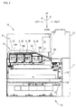
- FIG. 1 is a diagram showing the configuration of an image forming apparatus 10 according to an embodiment of the present disclosure.
- an up-down direction 6 is defined based on the state where an image forming apparatus 10 is installed to be usable (the state shown in FIG. 1 ).
- a front-rear direction 7 is defined on the supposition that the side on which an operation display portion 17 is provided in the above-mentioned installment state is the front side.
- a left-right direction 8 is defined based on the image forming apparatus 10 in the installment state viewed from the front side.
- the image forming apparatus 10 is a multifunction peripheral having a plurality of functions such as a print function, a copy function, a facsimile function, and a scan function.
- the image forming apparatus 10 is not limited to a multifunction peripheral, but may be any apparatus, such as a printer, a copier, or a facsimile apparatus, that has a print function.
- the image forming apparatus 10 includes an image reading portion 12 and an image forming portion 14.
- the image reading portion 12 performs a process of reading an image from a document sheet, and is provided in the upper part of the image forming apparatus 10.
- the image forming portion 14 performs a process of forming a color image based on the electrophotography, and is provided in the lower part of the image forming apparatus 10.
- a sheet discharge portion 15 is provided on the right side of the image forming portion 14.
- the sheet discharge portion 15 is formed in such a way as to couple the image forming portion 14 and the image reading portion 12 vertically with the discharge space 21 formed therebetween. As shown in FIG. 1 , the front side and the left side of the discharge space 21 are opened. In addition, the rear side of the discharge space 21 is not opened, but is closed by a rear panel or the like. Furthermore, the sheet discharge portion 15 is provided on the right side of the discharge space 21. In this way, the right side of the sheet discharge space 21 is closed by the sheet discharge portion 15.
- the sheet discharge portion 15 discharges a sheet member with an image formed thereon to the discharge space 21.
- a left side surface of the sheet discharge portion 15 that faces the discharge space 21 has a sheet discharge port 15A.
- the sheet discharge port 15A is formed above an end portion 24 of a sheet tray 18 that is described below. The sheet member is discharged from the sheet discharge port 15A.
- the image forming portion 14 includes a housing 11 as an apparatus main body.
- the components constituting the image forming portion 14 are arranged in the housing 11.
- the housing 11 includes an outer frame and an inner frame, wherein the outer frame covers the whole of the image forming portion 14, and the inner frame supports the components constituting the image forming portion 14.
- the housing 11, as a whole, has an approximately rectangular parallelepiped shape.
- the housing 11 includes a front cover 11A and a side cover 11B.
- the front cover 11A and the side cover 11B covers an opening 11C that is provided on the front side of the housing 11.
- the front cover 11A is pivoted around, as a fulcrum, near an upper end of a sheet cassette 27 between an attitude for opening the opening 11C of the housing 11 (see FIG. 2 ), and an attitude for closing the opening 11C (see FIG. 1 ).
- the side cover 11B is disposed above the front cover 11A.
- the side cover 11B is fixed to the housing 11 by a fixing tool such as a screw. With this configuration, the side cover 11B closes the upper part of the opening 11C that cannot be closed by the front cover 11A.
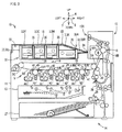
- FIG. 2 shows a state where the side cover 11B is removed and the front cover 11A is opened.
- FIG. 3 is a diagram showing the internal configuration of the image forming portion 14.
- the image reading portion 12 is omitted.
- the image forming portion 14 forms a color image on a sheet member such as a print sheet based on the so-called tandem system.
- the image forming portion 14 includes a plurality of image forming units 4, an intermediate transfer unit 5, a laser scanning device 13, a secondary transfer roller 20, a fixing device 16, a sheet tray 18, a sheet cassette 27, a sheet feed unit 28, an operation display portion 17 (see FIG. 1 ), a conveyance path 26, a container attachment portion 30 (case storage portion), and a control portion (not shown).
- the sheet feed unit 28 picks up, one by one, sheet members stacked in the sheet cassette 27, and feeds the sheet member toward the conveyance path 26.
- the image forming units 4 (4C, 4M, 4Y, and 4K) are provided below the intermediate transfer unit 5.
- the plurality of image forming units 4 are arranged in alignment along the running direction (the direction indicated by the arrow 19) of a transfer belt 5A.
- the image forming units 4Y for yellow color, 4C for cyan color, 4M for magenta color, and 4K for black color are disposed in the stated order.
- Each of the image forming units 4 includes a photoconductor drum 41, a charging device 42, a developing device 44, and a primary transfer roller 45.
- the image forming unit 4Y forms a toner image on the surface of the photoconductor drum 41 by using yellow toner.
- the image forming units 4C, 4M and 4K form toner images on the surfaces of the photoconductor drums 41 by using cyan toner, magenta toner, and black toner, respectively.
- the developing devices 44 respectively perform developing processes for developing the toner images on the photoconductor drums 41.
- the intermediate transfer unit 5 includes a transfer belt 5A, a driving roller 5B and a driven roller 5C.
- the transfer belt 5A is a belt member on which toner images of respective colors formed on the photoconductor drums 41 of the image forming units 4 are transferred.
- the transfer belt 5A is disposed above the photoconductor drums 41.
- the transfer belt 5A is an endless annular belt.
- the transfer belt 5A is supported by the driving roller 5B and the driven roller 5C that are separated from each other in the left-right direction 8, so as to be able to run around them.
- the transfer belt 5A is suspended between and supported by the driving roller 5B and the driven roller 5C.
- Each of the laser scanning devices 13 irradiates the surface of the photoconductor drum 41 of the image forming unit 4 with a laser beam based on input image data of a corresponding color. With this operation, electrostatic latent images are formed on the respective photoconductor drums 41.
- the secondary transfer roller 20 is disposed to face the driving roller 5B across the conveyance path 26 that extends vertically. By a transfer potential applied to the secondary transfer roller 20, the toner image on the transfer belt 5A is transferred to the sheet member. The sheet member with the toner image transferred thereon is conveyed to the fixing device 16.
- the fixing device 16 fixes the toner image transferred on the sheet member, to the sheet member by heating it.
- the fixing device 16 includes a heating roller 16A and a pressure roller 16B.
- the sheet member is conveyed while being nipped by the heating roller 16A and the pressure roller 16B. During this conveyance, heat is transmitted from the heating roller 16A to the toner image transferred on the sheet member, and the toner image is heated. This allows the toner image to be fixed to the sheet member. Subsequently, the sheet member is discharged to the sheet tray 18 by the sheet discharge portion 15.
- the sheet tray 18 is provided in the discharge space 21.
- the sheet tray 18 holds sheet members that each have been passed through the fixing device 16 and discharged to outside from the sheet discharge port 15A.
- the sheet tray 18 also serves as an outer frame that constitutes an upper surface of the image forming portion 14. Sheet members discharged to the sheet tray 18 are stacked thereon.
- a plurality of ribs 18A (see FIG. 2 ) extending in the left-right direction 8 are formed on the upper surface of the sheet tray 18 (sheet stacking surface). The sheet members discharged to the sheet tray 18 are supported by the upper ends of the ribs 18A.
- the sheet tray 18 is a plate-like member made of synthetic resin or the like, and extends in the left-right direction 8. Specifically, the sheet tray 18 extends from the left side surface of the sheet discharge portion 15 to the left side surface of the housing 11.
- the sheet tray 18 includes an inclined surface 18B and a horizontal surface 18C.
- the inclined surface 18B extends diagonally upward from a right side end portion 24 of the sheet tray 18 toward the left side, passes a support point 39A, namely an upper end 39 of a side wall 33R that is described below, and is further inclined diagonally upward at the same inclination angle from the support point 39A of the upper end 39.
- the horizontal surface 18C a portion on the other side (specifically, the left side) opposite to the inclined surface 18B in the left-right direction 8 is the horizontal surface 18C.
- the inclined surface 18B is inclined diagonally downward toward the sheet discharge portion 15 side.
- the horizontal surface 18C horizontally extends leftward from a left side end 23 of the inclined surface 18B.
- a storage space 22 is formed between the intermediate transfer unit 5 and the sheet tray 18.
- the container attachment portion 30 is provided in the storage space 22. That is, the sheet tray 18 is disposed above the container attachment portion 30, and the intermediate transfer unit 5 is disposed below the container attachment portion 30.
- the sheet tray 18 includes the inclined surface 18B and the horizontal surface 18C. As a result, the storage space 22 becomes gradually narrower from the end 23 that is a boundary between the horizontal surface 18C and the inclined surface 18B, toward the sheet discharge portion 15 side (right side).
- the container attachment portion 30 and the toner containers 3 are configured so that wasteful spaces around attachment position of the toner containers 3 can be reduced. In the following, the configurations of the container attachment portion 30 and the toner containers 3 are explained.
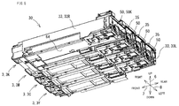
- FIG. 4 to FIG. 8 are diagrams showing the configuration of the container attachment portion 30.
- FIG. 4 is a persective view of the container attachment portion 30 viewed from front diagonally above.
- FIG. 5 is a persective view of the container attachment portion 30 viewed from rear diagonally below.
- FIG. 6 is a front view of the container attachment portion 30.
- FIG. 7 is a rear view of the container attachment portion 30.
- FIG. 8 is a partial perspective view showing the configuration of a front side portion of the container attachment portion 30.
- FIG. 4 to FIG. 7 each show an attached state of the toner containers 3.
- the container attachment portion 30 is fixed to the inner frame of the housing 11.
- the container attachment portion 30 holds the plurality of toner containers 3 (toner cases) in an attachable/detachable manner. That is, the toner containers 3 are attached to the container attachment portion 30 of the image forming apparatus 10 in the attachable/detachable manner.
- the container attachment portion 30 includes four storage chambers 31 (31Y, 31C, 31M and 31K) for storing the toner containers 3 of respective colors.
- the container attachment portion 30 supports the toner containers 3 in the corresponding storage chambers 31 in such a manner that the toner containers 3 can be slid in the front-rear direction 7.
- the four storage chambers 31 respectively correspond to the toner containers 3, and are arranged in alignment along the left-right direction 8.
- the container attachment portion 30 includes two side walls 33 (33L and 33R) at opposite ends in the left-right direction 8, a bottom plate 34 constituting a bottom surface, and three partition walls 35 that partition the space of the container attachment portion 30 in the left-right direction 8.
- Each partition wall 35 stands upright from the bottom plate 34 of the container attachment portion 30.
- the storage chambers 31 are spaces surrounded by the two side walls 33, the partition walls 35, and the bottom plate 34.
- a storage chamber 31K is disposed at the rightmost position to store a toner container 3K which contains black toner.
- storage chambers 31M, 31C and 31Y are provided in alignment in the stated order.
- the storage chamber 31M stores a toner container 3M containing magenta toner and is disposed adjacent to the storage chamber 31K.
- the storage chamber 31C stores a toner container 3C containing cyan toner.
- the storage chamber 31Y disposed at the leftmost position stores a toner container 3Y containing yellow toner.
- the toner container 3K is an example of the first toner case of the present disclosure
- the toner container 3M is an example of the second toner case of the present disclosure.
- An engaging hole 36 is formed in the bottom surface of each storage chamber 31 (see FIG. 8 ), wherein the engaging hole 36 is an example of the engaging portion.
- a lock claw 106 provided on each toner container 3 is inserted, wherein the lock claw 106 is described below.
- the lock claw 106 reaches and enters the engaging hole 36. This allows the toner container 3 to be locked in the drawing direction (front direction).
- fitting portions 37 are provided on the bottom surfaces of the storage chambers 31Y, 31C and 31M, such that the toner containers 3Y, 3C and 3M are selectively attached to the storage chambers 31Y, 31C and 31M, respectively.
- the storage chamber 31Y is provided with a fitting portion 37Y that allows attachment of only the toner container 3Y
- the storage chamber 31C is provided with a fitting portion 37C that allows attachment of only the toner container 3C.
- the storage chamber 31M is provided with a fitting portion 37M that allows attachment of only the toner container 3M.
- Each fitting portion 37 is a groove in which a rib 105 can be inserted, wherein the rib 105 is provided on a lower surface of the toner container 3 as a compatible member.
- the fitting portion 37 allows the toner container 3 to be attached to the storage chamber 31 when there is no shift between the rib 105 and the fitting portion 37.
- the fitting portion 37 does not engage with the rib 105, and the toner container 3 is prohibited from being attached to the storage chamber 31.
- each storage chamber 31 An upper side of each storage chamber 31 is opened.
- a sheet tray 18 is provided above the container attachment portion 30 in such a way as to cover the openings.
- the sheet tray 18 is supported by a plurality of projections 38 (see FIG. 4 ) that are provided on the upper end portions of the side walls 33 and the partition walls 35. That is, the ceiling surface of the container attachment portion 30 is constituted by a lower surface of the sheet tray 18.
- the storage chamber 31K is disposed below the inclined surface 18B of the sheet tray 18. In other words, the upper opening portion of the storage chamber 31K is covered with the inclined surface 18B. On the other hand, the upper opening portions of the other storage chambers 31Y, 31C and 31M are covered with the horizontal surface 18C. As a result, the storage chamber 31K is smaller than each of the other storage chambers 31Y, 31C and 31M in size in the height direction.
- the container attachment portion 30 is formed in a shape that corresponds to the storage space 22 so as to be installed in the storage space 22.
- the right side wall 33R is formed to be lower than the left side wall 33L and the partition walls 35.
- the left side wall 33L and the partition walls 35 have the same height.
- a height position of the upper end 39 of the side wall 33R is lower than the height positions of the side wall 33L and the partition walls 35 by a difference in the height direction between the horizontal surface 18C and the inclined surface 18B.
- intervals between the side walls 33 and the partition walls 35, namely, the widths of the respective storage chambers 31 are sized to correspond to the widths of the respective toner containers 3.
- the toner container 3K stored in the storage chamber 31K contains black toner that is consumed most and thus has a larger capacity than the other toner containers 3 (3Y, 3C and 3M).
- the storage chamber 31K is smaller than the other storage chambers 31 in size in the height direction due to the inclined surface 18B.
- the toner container 3K has a different shape from the other toner containers 3 (3Y, 3C and 3M).
- the black toner container 3K is wider than the other toner containers 3, and the upper part of the toner container 3K is formed to be inclined along the inclined surface 18B.
- FIG. 9 to FIG. 13B show the toner container 3M.
- FIG. 14 shows a state where a cover member 63 is removed from the toner container 3M.
- the toner containers 3Y and 3C for colors yellow and cyan have the same configuration as the toner container 3M.
- the configuration of the toner container 3M as a representative of the toner containers 3Y, 3C and 3M for respective colors.
- the vertical direction is represented as the up-down direction 6
- the insertion/drawing direction with respect to the container attachment portion 30 is represented as the front-rear direction 7
- the horizontal direction when viewed from the front in the attachment attitude is represented as the left-right direction 8.
- the toner container 3M supplies toner to the developing device 44 of the image forming unit 4M.
- the toner container 3M is attachable/detachable with respect to the container attachment portion 30 provided in the housing 11, and is supported such that it can be slid in the front-rear direction 7 when attached to and detached from the container attachment portion 30.
- the toner container 3M is formed to be long in the front-rear direction 7.
- the toner container 3M includes a case main body 60 and a cover member 63.
- the case main body 60 is formed to be long in the front-rear direction 7, and is composed of a housing 61 (housing main body) and a lid 62.
- the housing 61, the lid 62, and the cover member 63 are synthetic resin products made of synthetic resin such as ABS resin or PET resin.
- the housing 61 is for storing toner and is formed in the shape of a box that is long in the front-rear direction 7.
- the housing 61 has a large rectangular opening portion (upper-surface opening) at the top, and the opening portion is closed by the lid 62.
- the housing 61 stores toner that is used in the developing process by the developing device 44.
- a flange 65 is formed at the rim of the opening of the housing 61.
- the flange 65 is formed at the whole rim of the opening.
- the flange 65 is a portion that is joined with a rim portion 71 of the lid 62.
- the flange 65 and the rim portion 71 are, in the state where they are put together, welded and joined by an impulse welding machine or the like.
- a joint portion where the flange 65 and the rim portion 71 are joined together is referred to as a second joint portion 66.
- the lid 62 is formed in a shape that corresponds to the upper surface of the housing 61, and is formed in the shape of a rectangle that is long in the front-rear direction 7.
- the lid 62 is configured to cover the opening portion of the housing 61, and is formed in a flat shape of a small thickness.
- the lid 62 includes a rim portion 71 and an upper-surface stage portion 73 (high stage portion), wherein the rim portion 71 abuts on the flange 65 of the housing 61, and the upper-surface stage portion 73 is slightly swollen from the rim portion 71.
- the upper-surface stage portion 73 that is an upper surface of the lid 62, extends along the front-rear direction 7.
- a recessed portion 74 is formed in the rear side of the upper-surface stage portion 73.
- An identification sheet or a chip memory is attached to the recessed portion 74, wherein the identification sheet is read by a control portion of the image forming apparatus 10 for identification.
- a step portion 72 including a front end portion 731 of the upper-surface stage portion 73 is formed on the front end of the lid 62.
- a lower stage portion 76 is formed in front of the front end portion 731 of the upper-surface stage portion 73, wherein the lower stage portion 76 is lower than the upper-surface stage portion 73.
- the step portion 72 is composed of the front end portion 731 of the upper-surface stage portion 73 and the lower stage portion 76 that are formed on the upper surface of the lid 62 in alignment in the front-rear direction 7.
- the lower stage portion 76 is lower than the front end portion 731 in height position. In other words, the lower stage portion 76 is lower than the upper-surface stage portion 73.
- the lower stage portion 76 is formed in front of the front end portion 731, extending from the front end portion 731 to a front end 621 of the lid 62.
- the lower stage portion 76 has a flat plane (flat surface) that extends from the front end portion 731 to the end 621.
- the lower stage portion 76 is formed on the upper surface of the lid 62, when attaching the toner container 3M to the container attachment portion 30, the user can insert the toner container 3M to the depth of the storage chamber 31M while putting his/her finger on the lower stage portion 76.
- the user when drawing the toner container 3M from the container attachment portion 30, the user can insert his/her finger into the gap 79 that is between the lower stage portion 76 and the sheet tray 18 (see FIG. 13A and FIG. 13B ). As a result, the user can easily grip the toner container 3M in the attachment state while putting his/her finger on the lower stage portion 76.
- the cover member 63 has a handle 92. This enables the user to, for example, insert the forefinger of his/her right hand under the handle 92 to support the handle 92 from under, and put another finger (for example, the thumb) on the lower stage portion 76 to press it down. In this way, the user can grip the front end of the toner container 3M in a reliable manner.
- an inclined surface 77 is formed on a portion that extends from the upper-surface stage portion 73 to the lower stage portion 76.
- the lower stage portion 76 includes a rearside stage portion 761 and a front-side stage portion 762 (small stage portion).
- the upper surfaces of the stage portions 761 and 762 are flat planes (flat surfaces).
- the stage portion 762 is lower than the stage portion 761. That is, in the lower stage portion 76, the position of the stage portion 762 in the height direction is lower than the position of the stage portion 761 in the height direction.
- the stage portion 762 is formed in a region that extends, to the rim portion 71, from a position that is slightly closer to the front side than the intermediate position of the lower stage portion 76 in the front-rear direction 7.
- the step between the stage portion 761 and the stage portion 762 and the step between the stage portion 762 and the rim portion 71 both have small heights. In the present embodiment, each of these steps is smaller than the step between the lower stage portion 76 and the upper-surface stage portion 73.
- the step between the stage portion 761 and the stage portion 762 and the step between the stage portion 762 and the rim portion 71 are each less than one millimeter in height.
- an identifying portion 81 for identifying a unique pattern of the toner container 3M is provided on a lower surface (bottom surface) 64 of the housing 61.
- the identifying portion 81 is used to determine whether or not the toner container 3M is compatible with the image forming apparatus 10. It is determined that the toner container 3M is compatible with the image forming apparatus 10 if the toner container 3M is inserted into the container attachment portion 30 without interruption of an identification projection (not shown) to the identifying portion 81, the identification projection provided on the bottom surface of the storage chamber 31M.
- the identifying portion 81 is positioned to be slightly closer to the rear side than an approximate center of the lower surface 64 in the front-rear direction 7.
- a supply port 67 and a shutter member 68 are provided on the lower surface 64.
- the shutter member 68 opens and closes the supply port 67.
- the supply port 67 is an opening portion through which the toner stored in the toner container 3M is sent to the developing device 44 when the toner container 3M is attached to the attachment position of the container attachment portion 30.
- the supply port 67 is formed in the vicinity of the rear end of the lower surface 64, close to the right side in the rear end portion.
- a transmission portion 50 is provided in the rear end portion of the housing 61.
- the transmission portion 50 receives a rotational driving force which is input from the image forming apparatus 10 in the attachment state where the toner container 3M is attached to the container attachment portion 30.
- the transmission portion 50 is provided on a wall surface 58 (see FIG. 10 ) of the housing 61 located in depth (rear) in the attachment direction in which the toner container 3M is attached to the container attachment portion 30.
- the transmission portion 50 includes a joint 52, a small diameter gear 53, and a large diameter gear 54.
- the joint 52 is connected with a joint (not shown) provided in the container attachment portion 30.
- a gear is formed on a shaft of the joint 52, and the gear meshes with the small diameter gear 53.
- the small diameter gear 53 meshes with the large diameter gear 54.
- the large diameter gear 54 is connected with a stirring paddle (not shown) that is a driving member provided inside the toner container 3M.
- a pin member 56 is provided in the rear end portion of the housing 61.
- the pin member 56 projects rearward from the wall surface 58.
- the pin member 56 is provided at a position that corresponds to a positioning hole (not shown) provided in the container attachment portion 30.
- the pin member 56 is inserted in the positioning hole. This allows the toner container 3M to be positioned to the attachment position of the container attachment portion 30, and is thereby attached to the attachment position in a reliable manner.
- the cover member 63 is attached to a front surface 57 of the housing 61 (see FIG. 14 ).
- the cover member 63 covers the front surface 57 of the housing 61 in such a way as to protect a filling port 97 provided in the front surface 57, wherein the filling port 97 is described below.
- the front surface 57 has the filling port 97 through which the toner is filled in the case main body 60.
- the filling port 97 is disposed close to the right side in the front surface 57.
- Projections 84 are respectively formed at opposite ends of the front surface 57 in the left-right direction 8.
- a projection 84 on the left side projects leftward, and a projection 84 on the right side projects rightward.
- the cover member 63 is attached to the front surface 57 of the housing 61 by being engaged with the projections 84. Specifically, a pair of engaging holes 85 (see FIG. 11 and FIG.
- the cover member 63 are respectively formed in two opposite sides of the cover member 63 (the sides opposite to each other in the left-right direction 8) that are perpendicular to the front surface 57, and the cover member 63 is attached to the front surface 57 when the projections 84 are inserted into the engaging holes 85.
- the handle 92 is provided on a front wall 87 (a front-side end surface) of the cover member 63.
- the front wall 87 faces the front surface 57 when the cover member 63 is attached to the front surface 57.
- the handle 92 is gripped by the user when the toner container 3M is attached to or drawn from the container attachment portion 30, or carried.
- the handle 92 projects frontward from the front wall 87. More specifically, the handle 92 projects diagonally downward from the front wall 87.
- the front wall 87 has a circular opening 88 at a position corresponding to the filling port 97. Even in the state where the cover member 63 is attached to the front surface 57, the user can visually recognize the filling port 97 through the opening 88.
- the handle 92 is provided below the opening 88.
- the handle 92 includes a base portion 921 and a side wall portion 922 (closing wall).
- the base portion 921 projects frontward from the front wall 87. More specifically, the base portion 921 projects diagonally downward from the front wall 87.
- the root portion of the base portion 921 is connected to the front wall 87.
- the side wall portion 922 is formed between a left end portion of the base portion 921 and the front wall 87. With the provision of the side wall portion 922, a left space among a space between the base portion 921 and the front wall 87 is closed by the side wall portion 922. It is noted that a side wall portion is not provided in the right end portion of the base portion 921, and as shown in FIG. 12 , the right side of the base portion 921 is opened such that a finger of the user can be inserted therein.
- a recessed portion 89 is formed in the lower portion of the cover member 63.
- the recessed portion 89 extends in the left-right direction 8 such that opposite ends in the left-right direction 8 are opened.
- the cover member 63 is provided in the lower end side of the front wall 87.
- the cover member 63 is provided at the lower end of the front wall 87 and projects diagonally downward from the lower end.
- the handle 92 is disposed more on the front side than the recessed portion 89.
- the handle 92 and the recessed portion 89 form a space that is sufficient for the user to insert his/her finger therein.
- the user can insert his/her finger in the opening portion opposite to the side wall portion 922 behind the handle 92, and hook the finger on the handle 92 from below.
- the side wall portion 922 exists on the tip side in the insertion direction of the finger in the space behind the handle 92, the tip of the inserted finger abuts on the side wall portion 922 and the finger is disposed at a fixed position. This facilitates the operation of the handle 92, and thereby facilitates the operation of attaching or detaching the toner container 3M to/from the image forming apparatus 10. That is, the operability of the toner container 3M is improved.
- a plurality of dotted projections 95 are provided on the surface of the handle 92.
- the dotted projections 95 are formed on an inclined surface 923 which is an outer surface of the base portion 921 of the handle 92.
- three dotted projections 95 are provided.
- the dotted projections 95 are each formed in a semispherical shape projecting from the inclined surface 923.
- the dotted projections 95 are not limited to the semispherical shape.
- the dotted projections 95 are disposed at equal intervals along the left-right direction 8 on the surface of the handle 92.
- the user can feel the dotted projections 95 on his/her finger. With the feel of the dotted projections 95, the user can recognize the position of the handle 92 and grip it firmly in a reliable manner. As a result, even in the dark, the user can recognize the location of the handle 92 of a toner container 3M attached to the container attachment portion 30, and then grip it to draw the toner container 3M from the container attachment portion 30.
- dotted projections 95 are suitable for a situation where the user works in a low-visibility environment. In addition, such dotted projections 95 are useful for a user with a poor eyesight.
- the provision of the dotted projections 95 prevents the finger from slipping when the handle 92 is gripped from above, and facilitates gripping of the handle 92.
- a step portion 100 is provided in a lower part of the cover member 63.
- the step portion 100 is composed of a first stage portion 101 and a second stage portion 102 that are aligned in the left-right direction 8, namely, the short-length direction of the case main body 60.
- the first stage portion 101 is formed on the right side, and the second stage portion 102 is formed on the left side.
- the first stage portion 101 and the second stage portion 102 are different in height position. Specifically, the first stage portion 101 is higher in height position than the second stage portion 102.
- the step between the first stage portion 101 and the second stage portion 102 is sized to allow a finger of the user to be inserted therein.
- the first stage portion 101 is located away downward from a lower end portion 924 of the handle 92, and the second stage portion 102 is located below the first stage portion 101.
- the first stage portion 101 has a flat surface that extends from the second stage portion 102 rightward to the right side surface of the case main body 60.
- An engaging hole 86 is formed in the flat surface of the first stage portion 101 (see FIG. 10 ).
- a projection 83 projecting downward is formed on the front side of the lower surface 64 of the housing 61, and the projection 83 is inserted in the engaging hole 86 when the cover member 63 is attached to the front surface 57. This enhances the attachment of the cover member 63 to the housing 61.
- the rib 105 (compatible shape member) that can be inserted in the groove of the fitting portion 37, is provided on the lower surface of the second stage portion 102.
- the rib 105 is disposed at a position unique to the toner container 3M. That is, although the rib 105 is provided on each of the toner containers 3Y, 3C and 3M, the positions of the toner containers 3Y, 3C and 3M at which the ribs 105 are disposed differ from each other in the left-right direction 8.
- the rib 105 is disposed at a position that corresponds to the fitting portion 37 provided in the storage chamber 31M, namely, at a position that allows the rib 105 to be inserted in the groove of the fitting portion 37 when the toner container 3M is stored in the storage chamber 31M.
- the toner container 3M is allowed to be attached to the corresponding storage chamber 31M, but other toner containers 3Y and 3C are prohibited from being attached to the storage chamber 31M.
- the user can grip the front end portion of the toner container 3M by inserting his/her finger into a gap 107 between the first stage portion 101 and the bottom surface of the storage chamber 31M (see FIG. 13A ).
- the user can easily draw the toner container 3M by gripping the front end portion by inserting his/her finger into the gap 107.
- the user can insert the toner container 3M into the storage chamber 31M while putting his/her finger on the first stage portion 101. In this way, this configuration makes it possible to handle the toner container 3M easily during attachment and detachment thereof, and thus improves the operability of the toner container 3M.
- the cover member 63 since the lower surface of the cover member 63 is stepped, not flat, the user can easily understand visually that the stepped part is a gripping portion. In particular, since the gap 107 is formed at the bottom surface of the storage chamber 31M, the user can understand at a glance that the first stage portion 101 is a gripping portion. Thus, when detaching the toner container 3M, the user can grip the first stage portion 101 without hesitation.
- the cover member 63 includes a lock claw 106 (projection for locking) that projects downward from the lower surface thereof.
- the lock claw 106 is formed on the lower surface of the second stage portion 102.
- the lock claw 106 projects downward from the lower surface of the second stage portion 102.
- the lock claw 106 is located away rightward from the rib 105.
- the lock claw 106 is disposed at approximately the center of the lower surface of the cover member 63 in the left-right direction 8.
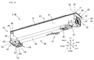
- FIG. 15 is a perspective view of the toner container 3K.
- the toner container 3K has approximately the same configuration as the other toner containers 3Y, 3C and 3M. Thus, in the following, description of the same configuration is omitted, and different configurations are described in detail. It is noted that, among the components of the toner container 3K, components that are also included in the other toner containers 3Y, 3C and 3M are assigned the same reference signs (for example, handle 92) added with an alphabet K (for example, handle 92K), and description thereof is omitted.
- the toner container 3K supplies toner to the developing device 44 of the image forming unit 4K.
- the toner container 3K is configured to be attachable to and detachable from the container attachment portion 30 provided in the housing 11. Specifically, the toner container 3K is supported so as to be slidable in the front-rear direction 7 so that it can be inserted into and pulled out from the storage chamber 31K which is disposed at the rightmost position in the container attachment portion 30.
- a major difference of the toner container 3K from the other toner containers 3Y, 3C and 3M is the shape of the toner container 3K.
- the storage chambers 31Y, 31C and 31M in which the toner containers 3Y, 3C and 3M are respectively stored have the same shape.
- the storage chamber 31K in which the toner container 3K is stored is lower in height and wider in the width direction than the other storage chambers 31Y, 31C and 31M. Accordingly, the toner container 3K attached to the storage chamber 31K is formed in a shape which is compatible with the storage chamber 31K, and as a result, is different from the other toner containers 3Y, 3C and 3M in shape.
- the toner container 3K includes a case main body 160 and a cover member 163.
- the case main body 160 is long in the front-rear direction 7, and includes a lower housing 161 (lower housing) and an upper housing 162 (upper housing).
- the lower housing 161, the upper housing 162, and the cover member 163 are synthetic resin products made of synthetic resin such as ABS resin or PET resin.
- the lower housing 161 defines a lower space in which the toner is stored, among the inner space of the case main body 160.
- the lower housing 161 has the same basic configuration as the housing 61, but is larger in horizontal width and smaller in height than the housing 61.
- a flange 65K of the lower housing 161 is located below the flange 65 of the housing 61.
- a first joint portion 166 that is described below is lower than the second joint portion 66 in height position.
- the upper housing 162 is provided above the lower housing 161.
- the upper housing 162 is joined with the lower housing 161 and defines an upper space among the inner space of the case main body 160.
- An opening portion (upper-surface opening) is formed in the upper surface of the lower housing 161, and a flange 65K is formed at the rim of the opening portion.
- an opening portion (lower-surface opening) is formed in the lower surface of the upper housing 162, and a flange 171 which is to be positioned with the flange 65K, is formed at the rim of the opening portion.
- first joint portion 166 a portion where the flange 65K and the flange 171 are joined together.
- the upper housing 162 includes an extension portion 201, which, different from the lids 62 of the other toner containers 3Y, 3C and 3M, projects upward from the flange 171.
- the extension portion 201 constitutes an upper part of the upper housing 162, and extends in the front-rear direction 7.
- the inside of the extension portion 201 is hollow.
- the extension portion 201 of the upper housing 162 includes an inclined portion 203 and an apex portion 204.
- the inclined portion 203 and the apex portion 204 are part of the extension portion 201.
- the inclined portion 203 is formed on the right side of the extension portion 201, and the apex portion 204 is formed on the left side of the extension portion 201.
- the inclined portion 203 has a shape that corresponds to the inclined shape of an inclined surface 18B of the sheet tray 18 that is a ceiling surface of the storage chamber 31K.
- the inclined portion 203 extends diagonally above left at a fixed inclination angle from the first joint portion 166 to the apex portion 204.
- the lower housing 161 In the attachment state where the toner container 3K is attached to the storage chamber 31K, the lower housing 161 is formed such that the flange 65K, which is at the upper end of the lower housing 161, is the same as the upper end 39 of the side wall 33R in height position. As a result, the first joint portion 166 is disposed at a height position that is approximately the same as that of the upper end 39 of the side wall 33R.
- the apex portion 204 is located immediately below the horizontal surface 18C of the sheet tray 18.
- the upper surface of the apex portion 204 is a flat surface that faces the horizontal surface 18C, and is at the same height position as the upper surfaces of the other adjacent toner containers 3Y, 3C and 3M.
- a step portion 172 is formed on the front side of the extension portion 201.
- the step portion 172 is formed on an end portion on the front side of the upper housing 162.
- the step portion 172 includes a first inclined surface 177 (upper step portion), a second inclined surface 175, and a lower stage portion 176, wherein the first inclined surface 177 is formed on the front end portion of the apex portion 204 and extends diagonally downward, the second inclined surface 175 extends downward from the lower end of the first inclined surface 177, and the lower stage portion 176 extends frontward from the second inclined surface 175.
- the first inclined surface 177, the second inclined surface 175, and the lower stage portion 176 are disposed in alignment in the front-rear direction 7.
- the second inclined surface 175 is inclined at a larger angle than the first inclined surface 177.
- the first inclined surface 177 is inclined at an approximate angle of 20 to 30 degrees
- the second inclined surface 175 is inclined at an approximate angle of 60 to 70 degrees.
- the lower stage portion 176 is lower than the apex portion 204, and, of course, lower than the first inclined surface 177 in height position. In other words, the lower stage portion 176 is lower than the apex portion 204 and the first inclined surface 177.
- the lower stage portion 176 is disposed more on the front side than the first inclined surface 177 and extends from the second inclined surface 175 to a front-side edge 1621 of the upper housing 162.
- the lower stage portion 176 has a flat plane (flat surface) in a region that extends from the lower end of the second inclined surface 175 to the edge 1621.
- the lower stage portion 176 includes a stage portion 178 of a small step (small stage portion) in a region that extends from the second inclined surface 175 to the flange 171.
- the upper surface of the stage portion 178 is a flat plane (flat surface).
- the difference in height between the stage portion 178 and the flange 171 is small, less than 1 mm.
- the user when attaching the toner container 3K to the container attachment portion 30, or when drawing the toner container 3K from the container attachment portion 30, the user can insert his/her finger into the gap between the lower stage portion 176 and the sheet tray 18. This makes it possible for the user to handle the toner container 3K easily while putting his/her finger on the lower stage portion 176.
- the toner container 3K includes a step portion 100K that is similar to the step portion 100 provided in each of the toner containers 3Y, 3C and 3M, but no member like the rib 105 is provided in a second stage portion 102K of the step portion 100K.
- the toner container 3K includes a transmission portion 50K that is similar to the transmission portion 50 provided in each of the toner containers 3Y, 3C and 3M, but among the components constituting the transmission portion 50K, a large diameter gear 54K is different from the large diameter gear 54 of the transmission portion 50 in disposition. Specifically, as shown in FIG. 7 , the position at which the large diameter gear 54K is disposed in the toner container 3K is lower than the position at which the large diameter gear 54 is disposed in each of the toner containers 3Y, 3C and 3M. Following this, a small diameter gear 53K is disposed more on the left side than a joint 52K.
- the lower housing 161 of the toner container 3K is smaller in height and larger in width than the housings 61 of the toner containers 3Y, 3C and 3M.
- the transmission path of the transmission portion 50K is designed to be closer to the horizontal direction than the transmission path of the transmission portion 50.
- the toner container 3K includes the upper housing 162 that includes the inclined portion 203.
- the first joint portion 166 from which the inclined portion 203 starts to be inclined is at approximately the same height as the upper end 39 of the side wall 33R.
- the toner container 3K can be suitably attached to the storage chamber 31K of the container attachment portion 30 that is disposed on the right side in the storage space 22, while ensuring a larger capacity for the toner container 3K than for each of the other toner containers 3Y, 3C and 3M. This makes it possible to reduce a wasteful space around the toner container 3K in the image forming apparatus 10, specifically a space between the side wall 33R of the storage chamber 31K and the sheet discharge portion 15.
- the present disclosure is not limited to this configuration.
- the present disclosure may have a configuration where the cover member 63 is not provided, and the handle 92, the step portion 100 and the like are formed in the case main body 60.
Landscapes
- Physics & Mathematics (AREA)
- General Physics & Mathematics (AREA)
- Electrophotography Configuration And Component (AREA)
- Dry Development In Electrophotography (AREA)
Applications Claiming Priority (1)
| Application Number | Priority Date | Filing Date | Title |
|---|---|---|---|
| JP2015167982A JP6447419B2 (ja) | 2015-08-27 | 2015-08-27 | トナー容器、及びトナー容器を備える画像形成装置 |
Publications (2)
| Publication Number | Publication Date |
|---|---|
| EP3144733A1 true EP3144733A1 (fr) | 2017-03-22 |
| EP3144733B1 EP3144733B1 (fr) | 2019-02-20 |
Family
ID=56360261
Family Applications (1)
| Application Number | Title | Priority Date | Filing Date |
|---|---|---|---|
| EP16177956.6A Active EP3144733B1 (fr) | 2015-08-27 | 2016-07-05 | Appareil de formation d'images |
Country Status (3)
| Country | Link |
|---|---|
| US (1) | US9760038B2 (fr) |
| EP (1) | EP3144733B1 (fr) |
| JP (1) | JP6447419B2 (fr) |
Families Citing this family (4)
| Publication number | Priority date | Publication date | Assignee | Title |
|---|---|---|---|---|
| JP7069794B2 (ja) * | 2018-02-15 | 2022-05-18 | 京セラドキュメントソリューションズ株式会社 | 画像形成装置 |
| USD947277S1 (en) * | 2018-09-21 | 2022-03-29 | Konica Minolta, Inc. | Electronic copying machine |
| USD947276S1 (en) * | 2018-09-26 | 2022-03-29 | Konica Minolta, Inc. | Electronic copying machine |
| JP7107213B2 (ja) * | 2018-12-26 | 2022-07-27 | 沖電気工業株式会社 | 現像剤収容体及び画像形成装置 |
Citations (4)
| Publication number | Priority date | Publication date | Assignee | Title |
|---|---|---|---|---|
| JP2006251002A (ja) * | 2005-03-08 | 2006-09-21 | Konica Minolta Business Technologies Inc | 画像形成装置およびトナーカートリッジ |
| EP2523047A1 (fr) * | 2011-03-22 | 2012-11-14 | Kyocera Document Solutions Inc. | Dispositif de transport de toner, toner contenant cette situation, appareil de formation d'images et procédé de commande du dispositif de transport de toner |
| EP2738620A2 (fr) * | 2012-11-29 | 2014-06-04 | Kyocera Document Solutions Inc. | Appareil de formation d'image et boîtier de toner |
| EP2911006A2 (fr) * | 2014-02-12 | 2015-08-26 | Kyocera Document Solutions Inc. | Dispositif de transport de toner et appareil de formation d'images comprenant celui-ci |
Family Cites Families (5)
| Publication number | Priority date | Publication date | Assignee | Title |
|---|---|---|---|---|
| JP3445202B2 (ja) | 1999-03-29 | 2003-09-08 | キヤノン株式会社 | トナー補給容器 |
| JP2009139680A (ja) * | 2007-12-07 | 2009-06-25 | Kyocera Mita Corp | 画像形成装置 |
| US20100054765A1 (en) * | 2008-09-02 | 2010-03-04 | Kabushiki Kaisha Toshiba | Developing device |
| JP5568514B2 (ja) * | 2011-06-10 | 2014-08-06 | 京セラドキュメントソリューションズ株式会社 | 画像形成装置及びトナー容器 |
| JP2014109629A (ja) * | 2012-11-30 | 2014-06-12 | Kyocera Document Solutions Inc | 画像形成装置 |
-
2015
- 2015-08-27 JP JP2015167982A patent/JP6447419B2/ja active Active
-
2016
- 2016-07-05 EP EP16177956.6A patent/EP3144733B1/fr active Active
- 2016-07-28 US US15/222,797 patent/US9760038B2/en active Active
Patent Citations (4)
| Publication number | Priority date | Publication date | Assignee | Title |
|---|---|---|---|---|
| JP2006251002A (ja) * | 2005-03-08 | 2006-09-21 | Konica Minolta Business Technologies Inc | 画像形成装置およびトナーカートリッジ |
| EP2523047A1 (fr) * | 2011-03-22 | 2012-11-14 | Kyocera Document Solutions Inc. | Dispositif de transport de toner, toner contenant cette situation, appareil de formation d'images et procédé de commande du dispositif de transport de toner |
| EP2738620A2 (fr) * | 2012-11-29 | 2014-06-04 | Kyocera Document Solutions Inc. | Appareil de formation d'image et boîtier de toner |
| EP2911006A2 (fr) * | 2014-02-12 | 2015-08-26 | Kyocera Document Solutions Inc. | Dispositif de transport de toner et appareil de formation d'images comprenant celui-ci |
Also Published As
| Publication number | Publication date |
|---|---|
| JP2017044910A (ja) | 2017-03-02 |
| EP3144733B1 (fr) | 2019-02-20 |
| US20170060026A1 (en) | 2017-03-02 |
| US9760038B2 (en) | 2017-09-12 |
| JP6447419B2 (ja) | 2019-01-09 |
Similar Documents
| Publication | Publication Date | Title |
|---|---|---|
| EP3144733B1 (fr) | Appareil de formation d'images | |
| US20140319766A1 (en) | Image forming apparatus | |
| US8565651B2 (en) | Toner supply device and image forming apparatus | |
| JP6665828B2 (ja) | 画像形成装置、画像形成装置に装着可能なトナー容器 | |
| JP6524958B2 (ja) | 画像形成装置、現像剤収容部の着脱規制方法 | |
| JP6602051B2 (ja) | 画像形成装置 | |
| JP6111689B2 (ja) | トナー補給装置 | |
| JP2013218039A (ja) | 現像剤収容容器およびこれを備えた現像装置、画像形成装置 | |
| JP6380619B2 (ja) | 画像形成装置 | |
| CN205193434U (zh) | 调色剂容器和具备调色剂容器的图像形成装置 | |
| US9535371B2 (en) | Toner container, image forming apparatus to which toner container is attached | |
| JP5914378B2 (ja) | 画像形成装置 | |
| CN106483795B (zh) | 调色剂容器和具备调色剂容器的图像形成装置 | |
| CN205139571U (zh) | 调色剂容器 | |
| CN205139569U (zh) | 调色剂容器 | |
| JP6610519B2 (ja) | 画像形成装置、画像形成装置に装着可能なトナー容器 | |
| EP1956440B1 (fr) | Appareil de formation d'images | |
| CN205139570U (zh) | 调色剂容器 | |
| CN205139568U (zh) | 调色剂容器 | |
| JP2019028135A (ja) | 画像形成装置 | |
| JP2009058642A (ja) | 画像形成装置 | |
| JP2019139188A (ja) | 画像形成装置およびトレイ | |
| JP6415237B2 (ja) | 画像形成装置 | |
| JP2008090210A (ja) | 画像形成装置 | |
| JP3163916U (ja) | 画像形成装置 |
Legal Events
| Date | Code | Title | Description |
|---|---|---|---|
| PUAI | Public reference made under article 153(3) epc to a published international application that has entered the european phase |
Free format text: ORIGINAL CODE: 0009012 |
|
| STAA | Information on the status of an ep patent application or granted ep patent |
Free format text: STATUS: THE APPLICATION HAS BEEN PUBLISHED |
|
| AK | Designated contracting states |
Kind code of ref document: A1 Designated state(s): AL AT BE BG CH CY CZ DE DK EE ES FI FR GB GR HR HU IE IS IT LI LT LU LV MC MK MT NL NO PL PT RO RS SE SI SK SM TR |
|
| AX | Request for extension of the european patent |
Extension state: BA ME |
|
| STAA | Information on the status of an ep patent application or granted ep patent |
Free format text: STATUS: REQUEST FOR EXAMINATION WAS MADE |
|
| 17P | Request for examination filed |
Effective date: 20170922 |
|
| RBV | Designated contracting states (corrected) |
Designated state(s): AL AT BE BG CH CY CZ DE DK EE ES FI FR GB GR HR HU IE IS IT LI LT LU LV MC MK MT NL NO PL PT RO RS SE SI SK SM TR |
|
| STAA | Information on the status of an ep patent application or granted ep patent |
Free format text: STATUS: EXAMINATION IS IN PROGRESS |
|
| 17Q | First examination report despatched |
Effective date: 20180507 |
|
| GRAP | Despatch of communication of intention to grant a patent |
Free format text: ORIGINAL CODE: EPIDOSNIGR1 |
|
| STAA | Information on the status of an ep patent application or granted ep patent |
Free format text: STATUS: GRANT OF PATENT IS INTENDED |
|
| INTG | Intention to grant announced |
Effective date: 20181210 |
|
| GRAS | Grant fee paid |
Free format text: ORIGINAL CODE: EPIDOSNIGR3 |
|
| GRAA | (expected) grant |
Free format text: ORIGINAL CODE: 0009210 |
|
| STAA | Information on the status of an ep patent application or granted ep patent |
Free format text: STATUS: THE PATENT HAS BEEN GRANTED |
|
| AK | Designated contracting states |
Kind code of ref document: B1 Designated state(s): AL AT BE BG CH CY CZ DE DK EE ES FI FR GB GR HR HU IE IS IT LI LT LU LV MC MK MT NL NO PL PT RO RS SE SI SK SM TR |
|
| REG | Reference to a national code |
Ref country code: GB Ref legal event code: FG4D |
|
| REG | Reference to a national code |
Ref country code: CH Ref legal event code: EP |
|
| REG | Reference to a national code |
Ref country code: DE Ref legal event code: R096 Ref document number: 602016010030 Country of ref document: DE |
|
| REG | Reference to a national code |
Ref country code: AT Ref legal event code: REF Ref document number: 1099003 Country of ref document: AT Kind code of ref document: T Effective date: 20190315 |
|
| REG | Reference to a national code |
Ref country code: IE Ref legal event code: FG4D |
|
| REG | Reference to a national code |
Ref country code: LT Ref legal event code: MG4D |
|
| REG | Reference to a national code |
Ref country code: NL Ref legal event code: MP Effective date: 20190220 |
|
| PG25 | Lapsed in a contracting state [announced via postgrant information from national office to epo] |
Ref country code: SE Free format text: LAPSE BECAUSE OF FAILURE TO SUBMIT A TRANSLATION OF THE DESCRIPTION OR TO PAY THE FEE WITHIN THE PRESCRIBED TIME-LIMIT Effective date: 20190220 Ref country code: LT Free format text: LAPSE BECAUSE OF FAILURE TO SUBMIT A TRANSLATION OF THE DESCRIPTION OR TO PAY THE FEE WITHIN THE PRESCRIBED TIME-LIMIT Effective date: 20190220 Ref country code: NO Free format text: LAPSE BECAUSE OF FAILURE TO SUBMIT A TRANSLATION OF THE DESCRIPTION OR TO PAY THE FEE WITHIN THE PRESCRIBED TIME-LIMIT Effective date: 20190520 Ref country code: PT Free format text: LAPSE BECAUSE OF FAILURE TO SUBMIT A TRANSLATION OF THE DESCRIPTION OR TO PAY THE FEE WITHIN THE PRESCRIBED TIME-LIMIT Effective date: 20190620 Ref country code: FI Free format text: LAPSE BECAUSE OF FAILURE TO SUBMIT A TRANSLATION OF THE DESCRIPTION OR TO PAY THE FEE WITHIN THE PRESCRIBED TIME-LIMIT Effective date: 20190220 |
|
| PG25 | Lapsed in a contracting state [announced via postgrant information from national office to epo] |
Ref country code: IS Free format text: LAPSE BECAUSE OF FAILURE TO SUBMIT A TRANSLATION OF THE DESCRIPTION OR TO PAY THE FEE WITHIN THE PRESCRIBED TIME-LIMIT Effective date: 20190620 Ref country code: GR Free format text: LAPSE BECAUSE OF FAILURE TO SUBMIT A TRANSLATION OF THE DESCRIPTION OR TO PAY THE FEE WITHIN THE PRESCRIBED TIME-LIMIT Effective date: 20190521 Ref country code: BG Free format text: LAPSE BECAUSE OF FAILURE TO SUBMIT A TRANSLATION OF THE DESCRIPTION OR TO PAY THE FEE WITHIN THE PRESCRIBED TIME-LIMIT Effective date: 20190520 Ref country code: NL Free format text: LAPSE BECAUSE OF FAILURE TO SUBMIT A TRANSLATION OF THE DESCRIPTION OR TO PAY THE FEE WITHIN THE PRESCRIBED TIME-LIMIT Effective date: 20190220 Ref country code: RS Free format text: LAPSE BECAUSE OF FAILURE TO SUBMIT A TRANSLATION OF THE DESCRIPTION OR TO PAY THE FEE WITHIN THE PRESCRIBED TIME-LIMIT Effective date: 20190220 Ref country code: LV Free format text: LAPSE BECAUSE OF FAILURE TO SUBMIT A TRANSLATION OF THE DESCRIPTION OR TO PAY THE FEE WITHIN THE PRESCRIBED TIME-LIMIT Effective date: 20190220 Ref country code: HR Free format text: LAPSE BECAUSE OF FAILURE TO SUBMIT A TRANSLATION OF THE DESCRIPTION OR TO PAY THE FEE WITHIN THE PRESCRIBED TIME-LIMIT Effective date: 20190220 |
|
| REG | Reference to a national code |
Ref country code: AT Ref legal event code: MK05 Ref document number: 1099003 Country of ref document: AT Kind code of ref document: T Effective date: 20190220 |
|
| PG25 | Lapsed in a contracting state [announced via postgrant information from national office to epo] |
Ref country code: AL Free format text: LAPSE BECAUSE OF FAILURE TO SUBMIT A TRANSLATION OF THE DESCRIPTION OR TO PAY THE FEE WITHIN THE PRESCRIBED TIME-LIMIT Effective date: 20190220 Ref country code: RO Free format text: LAPSE BECAUSE OF FAILURE TO SUBMIT A TRANSLATION OF THE DESCRIPTION OR TO PAY THE FEE WITHIN THE PRESCRIBED TIME-LIMIT Effective date: 20190220 Ref country code: CZ Free format text: LAPSE BECAUSE OF FAILURE TO SUBMIT A TRANSLATION OF THE DESCRIPTION OR TO PAY THE FEE WITHIN THE PRESCRIBED TIME-LIMIT Effective date: 20190220 Ref country code: SK Free format text: LAPSE BECAUSE OF FAILURE TO SUBMIT A TRANSLATION OF THE DESCRIPTION OR TO PAY THE FEE WITHIN THE PRESCRIBED TIME-LIMIT Effective date: 20190220 Ref country code: ES Free format text: LAPSE BECAUSE OF FAILURE TO SUBMIT A TRANSLATION OF THE DESCRIPTION OR TO PAY THE FEE WITHIN THE PRESCRIBED TIME-LIMIT Effective date: 20190220 Ref country code: EE Free format text: LAPSE BECAUSE OF FAILURE TO SUBMIT A TRANSLATION OF THE DESCRIPTION OR TO PAY THE FEE WITHIN THE PRESCRIBED TIME-LIMIT Effective date: 20190220 Ref country code: DK Free format text: LAPSE BECAUSE OF FAILURE TO SUBMIT A TRANSLATION OF THE DESCRIPTION OR TO PAY THE FEE WITHIN THE PRESCRIBED TIME-LIMIT Effective date: 20190220 Ref country code: IT Free format text: LAPSE BECAUSE OF FAILURE TO SUBMIT A TRANSLATION OF THE DESCRIPTION OR TO PAY THE FEE WITHIN THE PRESCRIBED TIME-LIMIT Effective date: 20190220 |
|
| REG | Reference to a national code |
Ref country code: DE Ref legal event code: R097 Ref document number: 602016010030 Country of ref document: DE |
|
| PG25 | Lapsed in a contracting state [announced via postgrant information from national office to epo] |
Ref country code: SM Free format text: LAPSE BECAUSE OF FAILURE TO SUBMIT A TRANSLATION OF THE DESCRIPTION OR TO PAY THE FEE WITHIN THE PRESCRIBED TIME-LIMIT Effective date: 20190220 Ref country code: PL Free format text: LAPSE BECAUSE OF FAILURE TO SUBMIT A TRANSLATION OF THE DESCRIPTION OR TO PAY THE FEE WITHIN THE PRESCRIBED TIME-LIMIT Effective date: 20190220 |
|
| PLBE | No opposition filed within time limit |
Free format text: ORIGINAL CODE: 0009261 |
|
| STAA | Information on the status of an ep patent application or granted ep patent |
Free format text: STATUS: NO OPPOSITION FILED WITHIN TIME LIMIT |
|
| PG25 | Lapsed in a contracting state [announced via postgrant information from national office to epo] |
Ref country code: AT Free format text: LAPSE BECAUSE OF FAILURE TO SUBMIT A TRANSLATION OF THE DESCRIPTION OR TO PAY THE FEE WITHIN THE PRESCRIBED TIME-LIMIT Effective date: 20190220 |
|
| 26N | No opposition filed |
Effective date: 20191121 |
|
| PG25 | Lapsed in a contracting state [announced via postgrant information from national office to epo] |
Ref country code: MC Free format text: LAPSE BECAUSE OF FAILURE TO SUBMIT A TRANSLATION OF THE DESCRIPTION OR TO PAY THE FEE WITHIN THE PRESCRIBED TIME-LIMIT Effective date: 20190220 Ref country code: SI Free format text: LAPSE BECAUSE OF FAILURE TO SUBMIT A TRANSLATION OF THE DESCRIPTION OR TO PAY THE FEE WITHIN THE PRESCRIBED TIME-LIMIT Effective date: 20190220 |
|
| REG | Reference to a national code |
Ref country code: CH Ref legal event code: PL |
|
| PG25 | Lapsed in a contracting state [announced via postgrant information from national office to epo] |
Ref country code: TR Free format text: LAPSE BECAUSE OF FAILURE TO SUBMIT A TRANSLATION OF THE DESCRIPTION OR TO PAY THE FEE WITHIN THE PRESCRIBED TIME-LIMIT Effective date: 20190220 |
|
| REG | Reference to a national code |
Ref country code: BE Ref legal event code: MM Effective date: 20190731 |
|
| PG25 | Lapsed in a contracting state [announced via postgrant information from national office to epo] |
Ref country code: BE Free format text: LAPSE BECAUSE OF NON-PAYMENT OF DUE FEES Effective date: 20190731 Ref country code: LI Free format text: LAPSE BECAUSE OF NON-PAYMENT OF DUE FEES Effective date: 20190731 Ref country code: LU Free format text: LAPSE BECAUSE OF NON-PAYMENT OF DUE FEES Effective date: 20190705 Ref country code: CH Free format text: LAPSE BECAUSE OF NON-PAYMENT OF DUE FEES Effective date: 20190731 |
|
| PG25 | Lapsed in a contracting state [announced via postgrant information from national office to epo] |
Ref country code: IE Free format text: LAPSE BECAUSE OF NON-PAYMENT OF DUE FEES Effective date: 20190705 |
|
| PG25 | Lapsed in a contracting state [announced via postgrant information from national office to epo] |
Ref country code: CY Free format text: LAPSE BECAUSE OF FAILURE TO SUBMIT A TRANSLATION OF THE DESCRIPTION OR TO PAY THE FEE WITHIN THE PRESCRIBED TIME-LIMIT Effective date: 20190220 |
|
| PG25 | Lapsed in a contracting state [announced via postgrant information from national office to epo] |
Ref country code: HU Free format text: LAPSE BECAUSE OF FAILURE TO SUBMIT A TRANSLATION OF THE DESCRIPTION OR TO PAY THE FEE WITHIN THE PRESCRIBED TIME-LIMIT; INVALID AB INITIO Effective date: 20160705 Ref country code: MT Free format text: LAPSE BECAUSE OF FAILURE TO SUBMIT A TRANSLATION OF THE DESCRIPTION OR TO PAY THE FEE WITHIN THE PRESCRIBED TIME-LIMIT Effective date: 20190220 |
|
| PG25 | Lapsed in a contracting state [announced via postgrant information from national office to epo] |
Ref country code: MK Free format text: LAPSE BECAUSE OF FAILURE TO SUBMIT A TRANSLATION OF THE DESCRIPTION OR TO PAY THE FEE WITHIN THE PRESCRIBED TIME-LIMIT Effective date: 20190220 |
|
| P01 | Opt-out of the competence of the unified patent court (upc) registered |
Effective date: 20230420 |
|
| PGFP | Annual fee paid to national office [announced via postgrant information from national office to epo] |
Ref country code: GB Payment date: 20250619 Year of fee payment: 10 |
|
| PGFP | Annual fee paid to national office [announced via postgrant information from national office to epo] |
Ref country code: FR Payment date: 20250620 Year of fee payment: 10 |
|
| PGFP | Annual fee paid to national office [announced via postgrant information from national office to epo] |
Ref country code: DE Payment date: 20250620 Year of fee payment: 10 |