EP3144796B1 - Dispositif électronique - Google Patents
Dispositif électronique Download PDFInfo
- Publication number
- EP3144796B1 EP3144796B1 EP16188315.2A EP16188315A EP3144796B1 EP 3144796 B1 EP3144796 B1 EP 3144796B1 EP 16188315 A EP16188315 A EP 16188315A EP 3144796 B1 EP3144796 B1 EP 3144796B1
- Authority
- EP
- European Patent Office
- Prior art keywords
- key
- measurement device
- keys
- user
- lock state
- Prior art date
- Legal status (The legal status is an assumption and is not a legal conclusion. Google has not performed a legal analysis and makes no representation as to the accuracy of the status listed.)
- Active
Links
Images


Classifications
-
- G—PHYSICS
- G06—COMPUTING OR CALCULATING; COUNTING
- G06F—ELECTRIC DIGITAL DATA PROCESSING
- G06F21/00—Security arrangements for protecting computers, components thereof, programs or data against unauthorised activity
- G06F21/70—Protecting specific internal or peripheral components, in which the protection of a component leads to protection of the entire computer
-
- G—PHYSICS
- G06—COMPUTING OR CALCULATING; COUNTING
- G06F—ELECTRIC DIGITAL DATA PROCESSING
- G06F3/00—Input arrangements for transferring data to be processed into a form capable of being handled by the computer; Output arrangements for transferring data from processing unit to output unit, e.g. interface arrangements
- G06F3/01—Input arrangements or combined input and output arrangements for interaction between user and computer
- G06F3/048—Interaction techniques based on graphical user interfaces [GUI]
- G06F3/0487—Interaction techniques based on graphical user interfaces [GUI] using specific features provided by the input device, e.g. functions controlled by the rotation of a mouse with dual sensing arrangements, or of the nature of the input device, e.g. tap gestures based on pressure sensed by a digitiser
- G06F3/0489—Interaction techniques based on graphical user interfaces [GUI] using specific features provided by the input device, e.g. functions controlled by the rotation of a mouse with dual sensing arrangements, or of the nature of the input device, e.g. tap gestures based on pressure sensed by a digitiser using dedicated keyboard keys or combinations thereof
-
- G—PHYSICS
- G01—MEASURING; TESTING
- G01J—MEASUREMENT OF INTENSITY, VELOCITY, SPECTRAL CONTENT, POLARISATION, PHASE OR PULSE CHARACTERISTICS OF INFRARED, VISIBLE OR ULTRAVIOLET LIGHT; COLORIMETRY; RADIATION PYROMETRY
- G01J1/00—Photometry, e.g. photographic exposure meter
- G01J1/02—Details
- G01J1/0228—Control of working procedures; Failure detection; Spectral bandwidth calculation
-
- G—PHYSICS
- G01—MEASURING; TESTING
- G01J—MEASUREMENT OF INTENSITY, VELOCITY, SPECTRAL CONTENT, POLARISATION, PHASE OR PULSE CHARACTERISTICS OF INFRARED, VISIBLE OR ULTRAVIOLET LIGHT; COLORIMETRY; RADIATION PYROMETRY
- G01J3/00—Spectrometry; Spectrophotometry; Monochromators; Measuring colours
- G01J3/02—Details
- G01J3/027—Control of working procedures of a spectrometer; Failure detection; Bandwidth calculation
-
- G—PHYSICS
- G06—COMPUTING OR CALCULATING; COUNTING
- G06F—ELECTRIC DIGITAL DATA PROCESSING
- G06F21/00—Security arrangements for protecting computers, components thereof, programs or data against unauthorised activity
- G06F21/30—Authentication, i.e. establishing the identity or authorisation of security principals
- G06F21/31—User authentication
Definitions
- the present disclosure relates to an electronic device, and more particularly, to an improvement in a lock function of locking an operation unit of an electronic device if necessary such that it is temporarily impossible to operate the operation unit.
- measurement devices which are configured to measure physical quantities which are objects to be measured and display the measurement results of the physical quantities for users and which include light-spectrum electronic devices such as an optical spectrum analyzer or a light wavelength meter for measuring and displaying spectrum information of light which is an object to be measured, and a light pulse tester (OTDR) for measuring and displaying loss distribution information in the longitudinal direction of a fiber which is an object to be measured.
- light-spectrum electronic devices such as an optical spectrum analyzer or a light wavelength meter for measuring and displaying spectrum information of light which is an object to be measured
- OTDR light pulse tester
- These measurement devices have input devices usable for users to perform various operations such as operations for setting various measurement conditions, operations for performing or interrupting a measuring operation, and an operation for performing a process of analyzing measurement results, such as a key operation unit having an array of a plurality of mechanical operation keys on an operation panel, or a touch panel which displays an array of a plurality of electronic operation keys on its display screen.
- the measurement devices have output devices, such as a liquid crystal display (LCD), for displaying (outputting) the statuses of settings of various measurement conditions, various set measurement conditions, the status of performance of a measuring operation, measurement results, and the like for users.
- LCD liquid crystal display
- some of the measurement devices have a lock function as a function of preventing a device from being operated by people other than a user when the user is temporarily away from the measurement device or preventing an erroneous operation such as an operation of erroneously stopping measurement in the middle of the measurement.
- This lock function means a function usable for a user to lock an operation state such that it is temporarily impossible to operate a device.
- a user of a measurement device which is configured as described above can measure characteristics which are objects to be measured by operating an input device, and can obtain a variety of information, such as the status of an operation of the measurement device and measurement results, from the display screen of an output device.
- FIG. 8 is a configuration block diagram illustrating an example of a light spectrum measurement device of the related art.
- a spectroscope 101 for example, through an optical fiber
- the spectroscope disperses the light, and extracts light of a desired wavelength component from the light to be measured, and outputs the extracted light.
- a light detector 102 is disposed such that its light receiving surface faces the spectroscope 101, and receives the light output from the spectroscope 101, and converts the received light into an electric signal (an analog signal), and outputs the electric signal.
- the light detector 102 for example, a photodiode can be used.
- An amplifier 103 amplifies the electric signal output from the light detector 102, and outputs the amplified electric signal.
- An A/D converter 104 converts the electric signal amplified by the amplifier 103, into a digital signal, and outputs the digital signal as measurement data to a bus B connected to a CPU 107.
- a storage unit 105 is composed of a hard disc, a random access memory (RAM), a read only memory (ROM), or the like, and is electrically connected to the CPU 107 through the bus B.
- the storage unit 105 stores programs to be executed by the CPU 107, such as a control program and a signal processing program, in advance, and temporarily stores various parameters such as measurement conditions and arithmetic operation conditions, and performs input/output of a variety of information in response to control of the CPU 107.
- An operation unit 106 is configured to have various operation buttons such as function keys and numeric keys, and output user's operation instructions, and is electrically connected to the CPU 107 through the bus B.
- the CPU 107 is electrically connected to the spectroscope 101, the light detector 102, the amplifier 103, the A/D converter 104, the storage unit 105, the operation unit 106, and a display unit 108 through the bus B, and acquires spectrum data by performing predetermined arithmetic processes, such as spectrum data correction, on the measurement data on the basis of the above-mentioned signal processing program while controlling each of those units on the basis of the above-mentioned control program, and displays the spectrum data on the display unit 108.
- predetermined arithmetic processes such as spectrum data correction
- the display unit 108 is configured to visualize and output the above-mentioned spectrum data, and is electrically connected to the CPU 107 through the bus B.
- the display unit 108 is composed of, for example, a liquid crystal display (LCD), a cathode ray tube (CRT), or the like.
- FIG. 9 is a view illustrating an example of the configuration of a front panel of the light spectrum measurement device which is configured as shown in FIG. 8 .
- a front panel 201 has the operation unit 106 configured as an input device usable for a user to perform various operation inputs, and the display unit 108 configured to visualize a variety of information, such as set measurement conditions, the status of an operation, and measurement results, and display (output) the visual information.
- the operation unit 106 configured as an input device usable for a user to perform various operation inputs
- the display unit 108 configured to visualize a variety of information, such as set measurement conditions, the status of an operation, and measurement results, and display (output) the visual information.
- the operation unit 106 includes various operation buttons of function keys 202, numeric keys 203, a lock operation key 204, and a software key part 205.
- the function keys 202 are composed of a plurality of keys usable for a user to input operations for instructing desired functions. Some keys of the function keys 202 each cause a corresponding function to be immediately executed if it is pressed, and the other keys of the function keys 202 each cause a plurality of associated functions to be displayed on the software key part 205 if it is pressed.
- the software key part 205 is composed of a plurality of software keys 207 which is displayed on the display unit 108, and a plurality of keys 206 for instructing the measurement device to perform the functions of corresponding software keys 207, respectively.
- the software keys 207 are configured such that the functions assigned to the individual keys are displayed as the names of the keys on the display unit 108. If the user presses any one function key 202, the names of a plurality of software keys associated with the function of the pressed key are displayed.
- SETUP which is one of the function keys 202 and corresponds to a measurement condition setting function
- RELAY which is the name of a key for setting the resolution of measurement
- SENSITIVITY which is the name of a key for setting the sensitivity of measurement
- AVERAGE which is the name of a key for setting the number of times of averaging of average measurement, and the like are displayed in a corresponding area of the software key part 205.
- a key 206 corresponding to the position of the corresponding software key 207.
- the user presses the second key 206 from the top, as a key corresponding to the software key.
- the numeric keys 203 are composed of a plurality of keys, such as numeric keys and an enter key usable for the user to input numerical parameters.
- the lock operation key 204 is a key usable for the user to input a locking or unlocking operation.
- the lock operation key 204 is separately provided as a key independent from the function keys 202.
- the lock operation key may be provided as one software key 207.
- FIG. 10 is a state transition view of the light measurement device of the related art which is configured as shown in FIGS. 8 and 9 and has a lock function, and shows a unlocked state 301 in which it is possible to operate the measurement device, and a lock state 302 in which it is impossible to operate the measurement device.
- the unlocked state 301 represents a pre-locking state in which the measurement device is unlocked and allows the user to operate the measurement device through the input device.
- the unlocked state 301 it is possible to perform various operations, such as operations of setting measurement conditions, operations for performing or interrupting a measuring operation, and an operation for performing an analyzing process on measurement results.
- the lock state 302 represents a state in which the user cannot perform every operation except for an unlocking operation.
- the measurement device does not execute a corresponding function.
- the measurement device in order to inform the user that the corresponding operation is invalid in the lock state, the measurement device can emit a beep sound or display a message on the display unit 108.
- an unlocking operation is processable. If the user performs a predetermined unlocking operation, the measurement device transitions to the unlocked state 301 such that it is possible to operate the measurement device.
- the unlocking operation is an operation of inputting an unlocking request of the user to the measurement device, such as pressing of a specific key such as the lock operation key 204, a password inputting operation, or inserting of a hardware key for unlocking.
- the user can switch the measurement device to the lock state 302 by performing a locking operation on the measurement device. In this way, the user can lock the operation state such that it is temporarily impossible to operate the measurement device.
- the user can prevent the measurement device from being operated by other people when the user is temporarily away from the measurement device, or prevent an erroneous operation such as an operation of erroneously stopping measurement in the middle of the measurement.
- FIG. 11 is a flow chart illustrating the flow of a key operation execution process of the light measurement device of the related art shown in FIG. 8 .
- the CPU 107 determines whether the current state of the measurement device is the unlocked state or the lock state.
- the CPU transitions to STEP S3 in which the CPU executes a predetermined process assigned to the operated key. Meanwhile, if it is determined that the current state is the lock state, in STEP S4, the CPU determines whether the input key operation is an unlocking operation.
- the CPU proceeds to STEP S3 in which the CPU executes a predetermined unlocking key process. Meanwhile, if it is determined that the input key operation is not an unlocking operation, in STEP S5, the CPU finishes the process flow without executing a key process.
- the user can switch the measurement device to the lock state by the key operation execution process. In this way, the user can lock the operation state of the measurement device such that every operation except for an unlocking operation is temporarily impossible.
- JPH07-067497A there is disclosed a technology related to a key lock function of locking various keys of the operation panel to keep functions selected by keys, operation conditions set by keys, and the like such that even through various keys are operated, signal inputs based on the operated keys are canceled.
- the user performs measurement at an arbitrary timing in a state where the settings of measurement conditions of the measurement device are fixed.
- the user wants to lock operation keys for setting measurement conditions such that it is impossible to change the measurement conditions by user's erroneous operations while keeping operation keys for measurement in the unlocked state such that a measuring operation is possible.
- the user may want to lock operation keys for setting such that it is possible to change some desired parameters but it is impossible to change the other parameters.
- US 2012/129496 A1 discloses a mobile terminal including a wireless communication unit configured to wirelessly communicate with at least one other terminal, a display unit including a touch screen, and a controller configured to enter the touch screen into a locked state, to display a lock screen and an application program icon for executing an application program on the lock screen when entering the locked state.
- US 2010/287490 A1 discloses a control method for controlling an information processing apparatus configured to display an operation screen including a plurality of keys on a display unit, and when any one of the plurality of keys is selected, to execute a process according to a process content registered in association with the selected key.
- the method includes setting, for each key of the plurality of keys, whether to cause the display unit to display a status of a process executed in response to selection of the selected key, and controlling the display unit to display the status of the process corresponding to the selected key if it is set to cause the display unit to display the status of the process executed in response to selection of the selected key when the key is selected, and to maintain display of the operation screen including the plurality of keys if it is not.
- US 2015 0 212 314 A1 discloses a spectroscopic measurement apparatus which includes an actuator that is driven by applying a drive voltage, a gap detector that detects a dimension of a gap, and a voltage control section including a feedback loop that controls the drive voltage depending on a detection result of the gap detector.
- the voltage control section includes a comparator that outputs a voltage signal at a High level if an absolute value of a deviation between a drive amount of the actuator and a setting value of the drive amount exceeds a predetermined threshold based on the detection result after a predetermined time elapses from the start of driving of the actuator.
- US 4 968 140 discloses a manual device for the detection of photometric values on a printed product which comprises a measuring head extruding from a housing into a measuring position.
- the measuring head is mounted together with its optical components on a measuring carriage, which may be displaced along the bottom of the housing by means of a drive motor between a rest position and a measuring position.
- the drive motor drives via a gear, a drive pulley and a grid axle for a monochromator.
- a sliding gear and a locking device are coordinated with the drive pulley, with the locking device immobilizing the measuring carriage precisely in the measuring position.
- the drive motor serves to displace the measuring carriage until the locking process essentially begins; and after this process, serves to rotate the grid axle.
- US 2007 0 257 895 A1 discloses a tactile display locking and marker system which includes enabling a touch screen; contacting a marker lock soft key on the touch screen; and disabling the touch screen including only detecting the marker lock soft key activation on the touch screen.
- Exemplary embodiments of the invention provides an electronic device including an operation unit and having an easily usable lock function of selectively permitting a user to perform desired operations even when the operation unit is locked, without locking every operation key of the operation unit without exception.
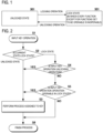
- FIG. 1 is a state transition view of a measurement device of an embodiment based on the present invention, and shows an unlocked state 301 in which it is possible to operate the measurement device, and a lock state 501 in which it is impossible to operate the measurement device.
- the unlocked state 301 represents a pre-locking state in which the measurement device is unlocked and allows the user to operate the measurement device through the input device, similarly to the unlocked state 301 of the related art shown in FIG. 10 .
- the unlocked state 301 it is possible to perform various operations, such as operations of setting measurement conditions, operations for performing or interrupting a measuring operation, and an operation for performing an analyzing process on measurement results.
- the lock state 501 shown in FIG. 1 is different from the lock state 302 of the related art shown in FIG. 10 .
- the lock state 302 of the related art it is impossible to perform every operation except for an unlocking operation.
- the lock state 501 of the present invention it is possible to operate functions set to be operable, in addition to an unlocking operation, but it is impossible to perform the other operations similarly in the lock state 302 of the related art.
- a function operable even in the lock state 501 is designated as an operation which the user wants to perform in the lock state, in advance, by operating an operation unit 106 while watching a display unit 108 when the measurement device is in the unlocked state 301.
- the user may specially designate any one of functions of the measurement device, as a function operable even in the lock state, and set the corresponding function as an option of the measurement device, or a specific function of the measurement device may be determined as a default state. In either case, before locking, a function operable even in the lock state is designated in advance.
- FIG. 2 is a flow chart illustrating the flow of a key operation execution process of the measurement device based on the present invention.
- the CPU 107 determines whether the current state of the measurement device is the unlocked state or the lock state.
- the CPU transitions to STEP S3 in which the CPU executes a predetermined process assigned to the operated key. Meanwhile, if it is determined that the current state is the lock state, in STEP S4, the CPU determines whether the input key operation is an unlocking operation.
- the CPU proceeds to STEP S3 in which the CPU executes a predetermined unlocking key process. Meanwhile, if it is determined that the input key operation is not an unlocking operation, in STEP S5, the CPU determines whether the input key operation is an operation executable even in the lock state.
- the CPU proceeds to STEP S3 in which the CPU performs the predetermined key process assigned to the operated key. Meanwhile, if it is determined that the input key operation is not an operation executable in the lock state, in STEP S6, the CPU finishes the process flow without performing the predetermined key process assigned to the operated key.
- the measurement device based on the present invention is switched to the lock state 501 by performing the key operation execution process described above, not every operation key is locked, and operations which the user has selected, designated, and set so as to be possible even in the lock state are possible.
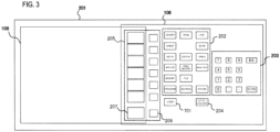
- FIG. 3 is a view illustrating an example of the configuration of a front panel of a light spectrum measurement device which is configured on the basis of the present invention.
- parts identical to those of FIG. 9 are denoted by the same reference symbols.
- a front panel 201 shown in FIG. 3 has a user key 701.
- the user can assign one or more functions operable even in the lock state 501, to software keys 207, and register the corresponding software keys in the user key 701, in advance.
- the user key 701 is a key for calling the software keys assigned in advance by the user. If the user presses the user key 701, the software keys 207 assigned in advance by the user are displayed in the software key part 205 of the display unit 108, and if the user presses a key 206 corresponding to a software key 207 to which a desired function has been assigned, the desired function is executed.
- FIG. 4 is a flow chart for explaining the flow of a process of registering software keys 207 to which desired functions have been assigned, in the user key 701.
- the user presses a function key 202 and a software key 207 corresponding to the desired key to be registered (STEP S2).
- the selected software key 207 is displayed on the display unit 108 (STEP S3).
- the user designates the position of any one of software keys 207 which have been displayed by pressing the user key 701 and in which the key selected in STEP S2 by pressing the software key 207 will be registered (STEP S4).
- the key selected in STEP S2 is registered (STEP S5).
- the user can register one or more software keys 207 to which desired functions have been assigned, in the user key 701, in advance.
- the user can perform specific operations registered in the user key 701, even in the lock state.
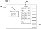
- FIG. 5 is an explanatory view of an application of the process of registering software keys 207 to which desired functions have been assigned, in the user key 701.
- a function key image 901 may be displayed on the display unit 108 as shown in FIG. 5 , and the user may designate a desired key on that image.
- one or more keys corresponding to the designated function key is displayed in a corresponding area of the software key 207.
- the user designates the desired software key to be registered in the user key, by a key 206, a mouse cursor on the display unit 108, or the like.
- the name of the designated software key is displayed in a user key registration window 902 displayed on the display unit 108.
- the user can exactly understand the software key which is the current registration object, on the basis of the display of the user key registration window 902.
- the user presses the user key 701 or selects the user key on the function key image 901 by a mouse cursor or the like.
- the software key 207 On the software key 207, one or more registered user key is displayed.
- the user designates the position of any one of software keys 207 of the user key where the software key displayed as the current registration object in the user key registration window 902 will be registered, as a registration position by pressing a key 206 or a software key 207 corresponding to the registration position.
- the CPU 107 stores information representing that the software key which is the current registration object is registered in the designated user key, in the storage unit 105, whereby the software key is registered as a user key.
- the user presses the user key 701 when user key registration is not being performed.
- the software key 207 area of the display unit 108 one or more software keys corresponding to information on software keys and the user key stored in the storage unit 105 is displayed.
- the user can select a software key to which a desired function has been assigned, from the displayed software keys, thereby performing the desired function.
- FIG. 3 an example of the measurement device in which the user key 701 is provided on the front panel 201 has been described.
- FIGS. 6 and 7 it is possible to set a software key which is operable even in a case where any user key is not provided on the front panel 201, that is, even in the lock state, without using any user key.
- FIG. 6 is a flow chart for explaining the flow of a process of registering software keys which are operable even in the lock state, without using any user key. according to the present invention.
- the user When designating a function which operable in the lock state 501 shown in FIG. 1 , the user presses a setting start key included in the operation unit 106, whereby the measurement device enters a setting mode (STEP S1). Subsequently, in order to select a desired key to be set as an operable key, the user presses a function key 202 including a desired function to be set (STEP S2).
- the names of a plurality of keys associated with the pressed key are displayed on software keys 207 (STEP S3).
- the storage unit 105 has information stored when starting to use the measurement device and representing whether the corresponding key is operable in the lock state 501.
- the CPU 107 determines whether each key has been set to be operable in the lock state 501, with reference to information stored in the storage unit 105 and representing whether the corresponding key is operable in the lock state, and displays the determination results such that the user can recognize the determination results.
- the CPU displays keys set to be operable, by white letters on a black background, and displays keys set to be inoperable, by black letters on a white background, such that the user can distinguish them.
- the CPU may surround each key set to be operable, with a frame border, for example, in red.
- the CPU 107 determines whether the key pressed in STEP S4 has been already set as an operable key, on the basis of information acquired from the storage unit 105 and representing whether the pressed key is operable in the lock state (STEP S5).
- the CPU sets the corresponding key as a key operable in the lock state, and stores information representing that the corresponding has been set as an operable key, in the storage unit 105 (STEP S6). Meanwhile, in a case where the pressed key has been stored as an operable key, the CPU sets the corresponding key as a key inoperable in the lock state, and stores information representing that the corresponding key has been set as an inoperable key, in the storage unit 105 (STEP S7).
- the user can designate keys which are operable in the lock state 501, before locking.
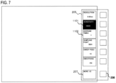
- FIG. 7 is a display screen example of the measurement device when an operation is being performed in the lock state after operable keys have been set, according to the present invention.
- a plurality of keys associated with the function key 202 is displayed on the software key part 205 of the display unit 108.
- the function key 202 includes operable keys and inoperable keys together.
- the operable keys are displayed, for example, by white letters on a black background, like a software key 1101, and the inoperable keys are displayed, for example, by black letters on a white background, like a software key 1102.
- the measurement device displays the "SENSITIVITY” key by white letters on a black background, thereby showing that the "SENSITIVITY” key is an operable key, and displays the "AVERAGE” key by black letters on a white background, thereby showing that the "AVERAGE” key is an inoperable key.
- operable keys and inoperable keys are displayed such that it is possible to distinguish them by the background colors of the keys, like the software key 1101 and the software key 1102.
- the present invention is not limited to that method.
- Operable keys may be surrounded with red frame borders, or only operable keys may be displayed without displaying inoperable keys.
- the user can clearly distinguish operable keys and inoperable keys in the lock state 501, and can press an operable key, thereby performing a desired processing function.
- the information set by the operation of setting keys operable in the lock state (the information on whether each key is operable in the lock state) is stored in the storage unit 105, and is retained even after the power is cut off.
- the state (the lock state) during power-off is held, and during the next power-on, it is possible to boot the measurement device while keeping the state (the lock state) during power-off.
- an electronic measurement device including an operation unit and having an easily usable lock function of selectively permitting a user to perform desired operations even when the operation unit is locked, without locking every operation key of the operation unit without exception.
Landscapes
- Engineering & Computer Science (AREA)
- Physics & Mathematics (AREA)
- Theoretical Computer Science (AREA)
- General Physics & Mathematics (AREA)
- General Engineering & Computer Science (AREA)
- Spectroscopy & Molecular Physics (AREA)
- Computer Security & Cryptography (AREA)
- Computer Hardware Design (AREA)
- Software Systems (AREA)
- Human Computer Interaction (AREA)
- Testing Or Calibration Of Command Recording Devices (AREA)
- Input From Keyboards Or The Like (AREA)
Claims (3)
- Dispositif de mesure électronique comprenant :une unité d'affichage (108) ;une unité de fonctionnement (106) comprenant une pluralité de touches logicielles pour réaliser des fonctions de fonctionnement pour faire fonctionner le dispositif de mesure électronique ; etune unité de traitement centrale (107) configurée pour commander l'unité d'affichage (108) pour afficher des données de mesure sur l'unité d'affichage (108), dans lequel :le dispositif de mesure électronique a une fonction de verrou de fonctions de fonctionnement de verrouillage sur l'unité de fonctionnement (106) de sorte que les fonctions de fonctionnement, à l'exception d'une fonction de déverrouillage, ne puissent temporairement pas fonctionner,le dispositif de mesure électronique est en outre configuré pour réaliser un procédé d'enregistrement de touches logicielles qui peuvent fonctionner même dans un état verrouillé de sorte qu'au moins une des fonctions de fonctionnement associées à la touche logicielle enregistrée soit réglée pour pouvoir fonctionner sélectivement même dans l'état verrouillé, en plus de la fonction de déverrouillage ;l'unité de traitement centrale (107) est configurée de sorte que l'au moins une de la pluralité de touches logicielles associée à la fonction de fonctionnement, qui est réglée pour pouvoir fonctionner sélectivement, soit affichée d'une manière qui peut être distinguée de touches logicielles associées à une fonction de fonctionnement qui ne peut temporairement pas fonctionner ;le dispositif de mesure électronique comprenant en outre une unité de stockage (105) configurée pour stocker des informations relatives à si chaque touche peut fonctionner dans l'état verrouillé et pour retenir ces informations même après que l'alimentation a été coupée ; etaprès que l'alimentation a été coupée dans l'état verrouillé, le dispositif de mesure électronique est configuré pour être amorcé durant un allumage suivant tout en conservant l'état verrouillé durant une extinction de sorte que l'état verrouillé ne soit pas levé.
- Dispositif de mesure électronique selon la revendication 1, dans lequel :l'unité d'affichage (108) a un écran d'affichage sur lequel la pluralité de touches logicielles est affichée, etl'unité de fonctionnement (106) comporteune pluralité de touches de fonctionnement (206) correspondant à la pluralité de touches logicielles (207) ;une pluralité de touches de fonctions (202) auxquelles des fonctions de traitement peuvent être assignées à l'avance, etune touche de commande de verrou (204) configurée pour recevoir une entrée pour régler l'état verrouillé ou lever le réglage de l'état verrouillé.
- Dispositif de mesure électronique selon l'une quelconque des revendications 1 ou 2, dans lequel :
le dispositif de mesure électronique est configuré pour mesurer une quantité physique qui est un objet devant être mesuré et afficher un résultat de mesure de la quantité physique.
Applications Claiming Priority (1)
| Application Number | Priority Date | Filing Date | Title |
|---|---|---|---|
| JP2015182617A JP6283638B2 (ja) | 2015-09-16 | 2015-09-16 | 光測定装置 |
Publications (2)
| Publication Number | Publication Date |
|---|---|
| EP3144796A1 EP3144796A1 (fr) | 2017-03-22 |
| EP3144796B1 true EP3144796B1 (fr) | 2024-04-03 |
Family
ID=57113025
Family Applications (1)
| Application Number | Title | Priority Date | Filing Date |
|---|---|---|---|
| EP16188315.2A Active EP3144796B1 (fr) | 2015-09-16 | 2016-09-12 | Dispositif électronique |
Country Status (3)
| Country | Link |
|---|---|
| US (1) | US10754990B2 (fr) |
| EP (1) | EP3144796B1 (fr) |
| JP (1) | JP6283638B2 (fr) |
Families Citing this family (1)
| Publication number | Priority date | Publication date | Assignee | Title |
|---|---|---|---|---|
| US11354393B2 (en) | 2018-02-01 | 2022-06-07 | Pelstar, Llc | Systems and methods for controlling units for a scale |
Citations (3)
| Publication number | Priority date | Publication date | Assignee | Title |
|---|---|---|---|---|
| US4968140A (en) * | 1988-02-02 | 1990-11-06 | Gretag Aktiengesellschaft | Manual device for the determination or measurement of photometric data using a measuring head |
| US20070257895A1 (en) * | 2006-05-08 | 2007-11-08 | Sunrise Telecom Incorporated | Tactile display locking and marker system |
| US20150212314A1 (en) * | 2014-01-27 | 2015-07-30 | Seko Epson Corporation | Actuator control device, optical module, and electronic apparatus |
Family Cites Families (22)
| Publication number | Priority date | Publication date | Assignee | Title |
|---|---|---|---|---|
| JP2736918B2 (ja) * | 1989-04-05 | 1998-04-08 | 日置電機株式会社 | 計測装置におけるキーロック制御方法 |
| JPH0734343Y2 (ja) * | 1990-02-07 | 1995-08-02 | 株式会社アドバンテスト | 測定器 |
| JPH04133119A (ja) * | 1990-09-26 | 1992-05-07 | Nec Corp | 情報入力用キーボード |
| JPH06161625A (ja) * | 1992-11-26 | 1994-06-10 | Sony Corp | コンピュータ |
| JPH0767497A (ja) | 1993-08-31 | 1995-03-14 | Janome Sewing Mach Co Ltd | 観賞魚飼育装置 |
| JPH08136398A (ja) * | 1994-11-09 | 1996-05-31 | Toyo Commun Equip Co Ltd | 光量測定用明暗室 |
| JPH10314174A (ja) * | 1997-05-21 | 1998-12-02 | Shimadzu Corp | 光測定装置 |
| JP4228617B2 (ja) * | 2001-09-07 | 2009-02-25 | ソニー株式会社 | 情報処理装置及び情報処理方法 |
| JP3920729B2 (ja) * | 2002-07-19 | 2007-05-30 | 三洋電機株式会社 | リモコンロックシステム |
| US7076312B2 (en) * | 2002-08-02 | 2006-07-11 | Fisher-Rosemount Systems, Inc. | Integrated electronic signatures for approval of process control and safety system software objects |
| JP2006040408A (ja) * | 2004-07-27 | 2006-02-09 | Sony Corp | 情報処理装置及びその設定方法 |
| US20070011461A1 (en) * | 2005-07-05 | 2007-01-11 | Yau-Ren Jeng | Personal data security system and method for handheld devices |
| US20080020803A1 (en) * | 2006-07-18 | 2008-01-24 | Motorola, Inc. | Methods and devices for restricting access to mobile communication device functionality |
| JP4468470B2 (ja) * | 2008-09-26 | 2010-05-26 | 株式会社東芝 | 放送受信装置およびプログラム |
| WO2010101629A1 (fr) * | 2009-03-01 | 2010-09-10 | Tau Science Corporation | Appareil de mesure de rendement quantique à vitesse élevée utilisant une source de lumière à semi-conducteurs |
| JP5506238B2 (ja) * | 2009-05-08 | 2014-05-28 | キヤノン株式会社 | 情報処理装置、情報処理装置の制御方法、及び、プログラム |
| WO2011130839A1 (fr) * | 2010-04-23 | 2011-10-27 | Jonathan Seliger | Système et procédé pour un métanavigateur internet pour des utilisateurs ayant des handicaps |
| US9027117B2 (en) * | 2010-10-04 | 2015-05-05 | Microsoft Technology Licensing, Llc | Multiple-access-level lock screen |
| KR101808625B1 (ko) * | 2010-11-23 | 2018-01-18 | 엘지전자 주식회사 | 콘텐츠 제어 장치 및 그 방법 |
| US9606643B2 (en) * | 2011-05-02 | 2017-03-28 | Microsoft Technology Licensing, Llc | Extended above the lock-screen experience |
| JP5743775B2 (ja) * | 2011-07-25 | 2015-07-01 | 京セラ株式会社 | 携帯機器 |
| JP6062519B1 (ja) * | 2015-09-28 | 2017-01-18 | 京セラ株式会社 | 電子機器及び電子機器の動作方法 |
-
2015
- 2015-09-16 JP JP2015182617A patent/JP6283638B2/ja active Active
-
2016
- 2016-09-12 EP EP16188315.2A patent/EP3144796B1/fr active Active
- 2016-09-15 US US15/266,501 patent/US10754990B2/en active Active
Patent Citations (3)
| Publication number | Priority date | Publication date | Assignee | Title |
|---|---|---|---|---|
| US4968140A (en) * | 1988-02-02 | 1990-11-06 | Gretag Aktiengesellschaft | Manual device for the determination or measurement of photometric data using a measuring head |
| US20070257895A1 (en) * | 2006-05-08 | 2007-11-08 | Sunrise Telecom Incorporated | Tactile display locking and marker system |
| US20150212314A1 (en) * | 2014-01-27 | 2015-07-30 | Seko Epson Corporation | Actuator control device, optical module, and electronic apparatus |
Also Published As
| Publication number | Publication date |
|---|---|
| JP2017058906A (ja) | 2017-03-23 |
| US10754990B2 (en) | 2020-08-25 |
| EP3144796A1 (fr) | 2017-03-22 |
| US20170076115A1 (en) | 2017-03-16 |
| JP6283638B2 (ja) | 2018-02-21 |
Similar Documents
| Publication | Publication Date | Title |
|---|---|---|
| JP2018197918A5 (fr) | ||
| US8854206B2 (en) | Sample measuring device and sample measuring system | |
| KR100689849B1 (ko) | 원격조정제어장치, 영상처리장치, 이를 포함하는 영상시스템 및 그 제어방법 | |
| JP2010102465A (ja) | Gui変更方法及び変更装置 | |
| CN113849089B (zh) | 用户界面控制设备和用于控制用户界面的方法 | |
| EP3144796B1 (fr) | Dispositif électronique | |
| CN111414115A (zh) | 按键控制方法、计算机可读存储介质及其终端 | |
| CN114077210B (zh) | 信息处理方法、装置及多功能设备 | |
| US11940327B2 (en) | Color measuring system and program | |
| JP2001021451A (ja) | 光パルス試験器 | |
| US9063022B2 (en) | Warm-up operation display device of chassis dynamometer system | |
| US20050210503A1 (en) | Remote control unit guide display | |
| CN112957003A (zh) | 色觉障碍检测方法、装置、设备及计算机可读存储介质 | |
| EP3247097B1 (fr) | Appareil d'impression, son procédé de commande et support d'informations | |
| CN105900416A (zh) | 用于适调与用户界面元素显示有关之暂时控制状态时段的消费设备及方法 | |
| JP2008080497A (ja) | 色校正方法、色校正装置、色校正プログラムおよびそのプログラムを記録した記録媒体 | |
| KR100494169B1 (ko) | 듀얼 모니터의 영상신호 처리장치 및 방법 | |
| KR100768806B1 (ko) | 텔레비전 시스템의 리모컨 선택 설정 제어 방법 | |
| WO2025224902A1 (fr) | Programme d'aide au dessin, dispositif d'aide au dessin, système d'aide au dessin et procédé d'aide au dessin | |
| JP2005250112A (ja) | 画像信号発生装置、画像表示装置、画像表示装置のオンライン制御方法 | |
| KR101322707B1 (ko) | 유저 인터페이스를 표시하는 디스플레이 장치 및 그 방법 | |
| JP2005055290A (ja) | 測定条件確認機能を備えた分析装置 | |
| JP2012008653A (ja) | 表示器及びそれを用いた表示システム | |
| CN115080939A (zh) | 快速进入工程模式的方法、装置、设备及可读存储介质 | |
| US20200041341A1 (en) | Diagnosis Assistance Device For Optical Characteristic Measurement Device, And Diagnosis Assistance Method For Optical Characteristic Measurement Device |
Legal Events
| Date | Code | Title | Description |
|---|---|---|---|
| PUAI | Public reference made under article 153(3) epc to a published international application that has entered the european phase |
Free format text: ORIGINAL CODE: 0009012 |
|
| STAA | Information on the status of an ep patent application or granted ep patent |
Free format text: STATUS: THE APPLICATION HAS BEEN PUBLISHED |
|
| AK | Designated contracting states |
Kind code of ref document: A1 Designated state(s): AL AT BE BG CH CY CZ DE DK EE ES FI FR GB GR HR HU IE IS IT LI LT LU LV MC MK MT NL NO PL PT RO RS SE SI SK SM TR |
|
| AX | Request for extension of the european patent |
Extension state: BA ME |
|
| STAA | Information on the status of an ep patent application or granted ep patent |
Free format text: STATUS: REQUEST FOR EXAMINATION WAS MADE |
|
| 17P | Request for examination filed |
Effective date: 20170922 |
|
| RBV | Designated contracting states (corrected) |
Designated state(s): AL AT BE BG CH CY CZ DE DK EE ES FI FR GB GR HR HU IE IS IT LI LT LU LV MC MK MT NL NO PL PT RO RS SE SI SK SM TR |
|
| RAP1 | Party data changed (applicant data changed or rights of an application transferred) |
Owner name: YOKOGAWA ELECTRIC CORPORATION Owner name: YOKOGAWA TEST & MEASUREMENT CORPORATION |
|
| STAA | Information on the status of an ep patent application or granted ep patent |
Free format text: STATUS: EXAMINATION IS IN PROGRESS |
|
| 17Q | First examination report despatched |
Effective date: 20200618 |
|
| RAP3 | Party data changed (applicant data changed or rights of an application transferred) |
Owner name: YOKOGAWA TEST & MEASUREMENT CORPORATION Owner name: YOKOGAWA ELECTRIC CORPORATION |
|
| REG | Reference to a national code |
Ref country code: DE Free format text: PREVIOUS MAIN CLASS: G06F0003048900 Ref legal event code: R079 Ref document number: 602016086630 Country of ref document: DE Ipc: G01J0003020000 |
|
| RIC1 | Information provided on ipc code assigned before grant |
Ipc: G06F 21/70 20130101ALI20230921BHEP Ipc: G01J 3/02 20060101AFI20230921BHEP |
|
| GRAP | Despatch of communication of intention to grant a patent |
Free format text: ORIGINAL CODE: EPIDOSNIGR1 |
|
| STAA | Information on the status of an ep patent application or granted ep patent |
Free format text: STATUS: GRANT OF PATENT IS INTENDED |
|
| INTG | Intention to grant announced |
Effective date: 20231030 |
|
| GRAS | Grant fee paid |
Free format text: ORIGINAL CODE: EPIDOSNIGR3 |
|
| GRAA | (expected) grant |
Free format text: ORIGINAL CODE: 0009210 |
|
| STAA | Information on the status of an ep patent application or granted ep patent |
Free format text: STATUS: THE PATENT HAS BEEN GRANTED |
|
| AK | Designated contracting states |
Kind code of ref document: B1 Designated state(s): AL AT BE BG CH CY CZ DE DK EE ES FI FR GB GR HR HU IE IS IT LI LT LU LV MC MK MT NL NO PL PT RO RS SE SI SK SM TR |
|
| REG | Reference to a national code |
Ref country code: GB Ref legal event code: FG4D |
|
| REG | Reference to a national code |
Ref country code: CH Ref legal event code: EP |
|
| REG | Reference to a national code |
Ref country code: IE Ref legal event code: FG4D |
|
| REG | Reference to a national code |
Ref country code: DE Ref legal event code: R096 Ref document number: 602016086630 Country of ref document: DE |
|
| REG | Reference to a national code |
Ref country code: LT Ref legal event code: MG9D |
|
| REG | Reference to a national code |
Ref country code: NL Ref legal event code: MP Effective date: 20240403 |
|
| REG | Reference to a national code |
Ref country code: AT Ref legal event code: MK05 Ref document number: 1672823 Country of ref document: AT Kind code of ref document: T Effective date: 20240403 |
|
| PG25 | Lapsed in a contracting state [announced via postgrant information from national office to epo] |
Ref country code: NL Free format text: LAPSE BECAUSE OF FAILURE TO SUBMIT A TRANSLATION OF THE DESCRIPTION OR TO PAY THE FEE WITHIN THE PRESCRIBED TIME-LIMIT Effective date: 20240403 |
|
| PG25 | Lapsed in a contracting state [announced via postgrant information from national office to epo] |
Ref country code: NL Free format text: LAPSE BECAUSE OF FAILURE TO SUBMIT A TRANSLATION OF THE DESCRIPTION OR TO PAY THE FEE WITHIN THE PRESCRIBED TIME-LIMIT Effective date: 20240403 |
|
| PG25 | Lapsed in a contracting state [announced via postgrant information from national office to epo] |
Ref country code: IS Free format text: LAPSE BECAUSE OF FAILURE TO SUBMIT A TRANSLATION OF THE DESCRIPTION OR TO PAY THE FEE WITHIN THE PRESCRIBED TIME-LIMIT Effective date: 20240803 |
|
| PG25 | Lapsed in a contracting state [announced via postgrant information from national office to epo] |
Ref country code: BG Free format text: LAPSE BECAUSE OF FAILURE TO SUBMIT A TRANSLATION OF THE DESCRIPTION OR TO PAY THE FEE WITHIN THE PRESCRIBED TIME-LIMIT Effective date: 20240403 |
|
| PG25 | Lapsed in a contracting state [announced via postgrant information from national office to epo] |
Ref country code: HR Free format text: LAPSE BECAUSE OF FAILURE TO SUBMIT A TRANSLATION OF THE DESCRIPTION OR TO PAY THE FEE WITHIN THE PRESCRIBED TIME-LIMIT Effective date: 20240403 Ref country code: FI Free format text: LAPSE BECAUSE OF FAILURE TO SUBMIT A TRANSLATION OF THE DESCRIPTION OR TO PAY THE FEE WITHIN THE PRESCRIBED TIME-LIMIT Effective date: 20240403 |
|
| PG25 | Lapsed in a contracting state [announced via postgrant information from national office to epo] |
Ref country code: GR Free format text: LAPSE BECAUSE OF FAILURE TO SUBMIT A TRANSLATION OF THE DESCRIPTION OR TO PAY THE FEE WITHIN THE PRESCRIBED TIME-LIMIT Effective date: 20240704 |
|
| PG25 | Lapsed in a contracting state [announced via postgrant information from national office to epo] |
Ref country code: PT Free format text: LAPSE BECAUSE OF FAILURE TO SUBMIT A TRANSLATION OF THE DESCRIPTION OR TO PAY THE FEE WITHIN THE PRESCRIBED TIME-LIMIT Effective date: 20240805 |
|
| PG25 | Lapsed in a contracting state [announced via postgrant information from national office to epo] |
Ref country code: ES Free format text: LAPSE BECAUSE OF FAILURE TO SUBMIT A TRANSLATION OF THE DESCRIPTION OR TO PAY THE FEE WITHIN THE PRESCRIBED TIME-LIMIT Effective date: 20240403 |
|
| PG25 | Lapsed in a contracting state [announced via postgrant information from national office to epo] |
Ref country code: CZ Free format text: LAPSE BECAUSE OF FAILURE TO SUBMIT A TRANSLATION OF THE DESCRIPTION OR TO PAY THE FEE WITHIN THE PRESCRIBED TIME-LIMIT Effective date: 20240403 |
|
| PG25 | Lapsed in a contracting state [announced via postgrant information from national office to epo] |
Ref country code: AT Free format text: LAPSE BECAUSE OF FAILURE TO SUBMIT A TRANSLATION OF THE DESCRIPTION OR TO PAY THE FEE WITHIN THE PRESCRIBED TIME-LIMIT Effective date: 20240403 |
|
| PG25 | Lapsed in a contracting state [announced via postgrant information from national office to epo] |
Ref country code: PL Free format text: LAPSE BECAUSE OF FAILURE TO SUBMIT A TRANSLATION OF THE DESCRIPTION OR TO PAY THE FEE WITHIN THE PRESCRIBED TIME-LIMIT Effective date: 20240403 |
|
| PG25 | Lapsed in a contracting state [announced via postgrant information from national office to epo] |
Ref country code: LV Free format text: LAPSE BECAUSE OF FAILURE TO SUBMIT A TRANSLATION OF THE DESCRIPTION OR TO PAY THE FEE WITHIN THE PRESCRIBED TIME-LIMIT Effective date: 20240403 |
|
| PG25 | Lapsed in a contracting state [announced via postgrant information from national office to epo] |
Ref country code: PT Free format text: LAPSE BECAUSE OF FAILURE TO SUBMIT A TRANSLATION OF THE DESCRIPTION OR TO PAY THE FEE WITHIN THE PRESCRIBED TIME-LIMIT Effective date: 20240805 Ref country code: PL Free format text: LAPSE BECAUSE OF FAILURE TO SUBMIT A TRANSLATION OF THE DESCRIPTION OR TO PAY THE FEE WITHIN THE PRESCRIBED TIME-LIMIT Effective date: 20240403 Ref country code: NO Free format text: LAPSE BECAUSE OF FAILURE TO SUBMIT A TRANSLATION OF THE DESCRIPTION OR TO PAY THE FEE WITHIN THE PRESCRIBED TIME-LIMIT Effective date: 20240703 Ref country code: LV Free format text: LAPSE BECAUSE OF FAILURE TO SUBMIT A TRANSLATION OF THE DESCRIPTION OR TO PAY THE FEE WITHIN THE PRESCRIBED TIME-LIMIT Effective date: 20240403 Ref country code: IS Free format text: LAPSE BECAUSE OF FAILURE TO SUBMIT A TRANSLATION OF THE DESCRIPTION OR TO PAY THE FEE WITHIN THE PRESCRIBED TIME-LIMIT Effective date: 20240803 Ref country code: HR Free format text: LAPSE BECAUSE OF FAILURE TO SUBMIT A TRANSLATION OF THE DESCRIPTION OR TO PAY THE FEE WITHIN THE PRESCRIBED TIME-LIMIT Effective date: 20240403 Ref country code: GR Free format text: LAPSE BECAUSE OF FAILURE TO SUBMIT A TRANSLATION OF THE DESCRIPTION OR TO PAY THE FEE WITHIN THE PRESCRIBED TIME-LIMIT Effective date: 20240704 Ref country code: FI Free format text: LAPSE BECAUSE OF FAILURE TO SUBMIT A TRANSLATION OF THE DESCRIPTION OR TO PAY THE FEE WITHIN THE PRESCRIBED TIME-LIMIT Effective date: 20240403 Ref country code: ES Free format text: LAPSE BECAUSE OF FAILURE TO SUBMIT A TRANSLATION OF THE DESCRIPTION OR TO PAY THE FEE WITHIN THE PRESCRIBED TIME-LIMIT Effective date: 20240403 Ref country code: CZ Free format text: LAPSE BECAUSE OF FAILURE TO SUBMIT A TRANSLATION OF THE DESCRIPTION OR TO PAY THE FEE WITHIN THE PRESCRIBED TIME-LIMIT Effective date: 20240403 Ref country code: BG Free format text: LAPSE BECAUSE OF FAILURE TO SUBMIT A TRANSLATION OF THE DESCRIPTION OR TO PAY THE FEE WITHIN THE PRESCRIBED TIME-LIMIT Effective date: 20240403 Ref country code: AT Free format text: LAPSE BECAUSE OF FAILURE TO SUBMIT A TRANSLATION OF THE DESCRIPTION OR TO PAY THE FEE WITHIN THE PRESCRIBED TIME-LIMIT Effective date: 20240403 Ref country code: RS Free format text: LAPSE BECAUSE OF FAILURE TO SUBMIT A TRANSLATION OF THE DESCRIPTION OR TO PAY THE FEE WITHIN THE PRESCRIBED TIME-LIMIT Effective date: 20240703 |
|
| REG | Reference to a national code |
Ref country code: DE Ref legal event code: R097 Ref document number: 602016086630 Country of ref document: DE |
|
| PG25 | Lapsed in a contracting state [announced via postgrant information from national office to epo] |
Ref country code: DK Free format text: LAPSE BECAUSE OF FAILURE TO SUBMIT A TRANSLATION OF THE DESCRIPTION OR TO PAY THE FEE WITHIN THE PRESCRIBED TIME-LIMIT Effective date: 20240403 |
|
| PG25 | Lapsed in a contracting state [announced via postgrant information from national office to epo] |
Ref country code: EE Free format text: LAPSE BECAUSE OF FAILURE TO SUBMIT A TRANSLATION OF THE DESCRIPTION OR TO PAY THE FEE WITHIN THE PRESCRIBED TIME-LIMIT Effective date: 20240403 |
|
| PG25 | Lapsed in a contracting state [announced via postgrant information from national office to epo] |
Ref country code: SK Free format text: LAPSE BECAUSE OF FAILURE TO SUBMIT A TRANSLATION OF THE DESCRIPTION OR TO PAY THE FEE WITHIN THE PRESCRIBED TIME-LIMIT Effective date: 20240403 Ref country code: RO Free format text: LAPSE BECAUSE OF FAILURE TO SUBMIT A TRANSLATION OF THE DESCRIPTION OR TO PAY THE FEE WITHIN THE PRESCRIBED TIME-LIMIT Effective date: 20240403 |
|
| PG25 | Lapsed in a contracting state [announced via postgrant information from national office to epo] |
Ref country code: SM Free format text: LAPSE BECAUSE OF FAILURE TO SUBMIT A TRANSLATION OF THE DESCRIPTION OR TO PAY THE FEE WITHIN THE PRESCRIBED TIME-LIMIT Effective date: 20240403 |
|
| PG25 | Lapsed in a contracting state [announced via postgrant information from national office to epo] |
Ref country code: SM Free format text: LAPSE BECAUSE OF FAILURE TO SUBMIT A TRANSLATION OF THE DESCRIPTION OR TO PAY THE FEE WITHIN THE PRESCRIBED TIME-LIMIT Effective date: 20240403 Ref country code: SK Free format text: LAPSE BECAUSE OF FAILURE TO SUBMIT A TRANSLATION OF THE DESCRIPTION OR TO PAY THE FEE WITHIN THE PRESCRIBED TIME-LIMIT Effective date: 20240403 Ref country code: RO Free format text: LAPSE BECAUSE OF FAILURE TO SUBMIT A TRANSLATION OF THE DESCRIPTION OR TO PAY THE FEE WITHIN THE PRESCRIBED TIME-LIMIT Effective date: 20240403 Ref country code: EE Free format text: LAPSE BECAUSE OF FAILURE TO SUBMIT A TRANSLATION OF THE DESCRIPTION OR TO PAY THE FEE WITHIN THE PRESCRIBED TIME-LIMIT Effective date: 20240403 Ref country code: DK Free format text: LAPSE BECAUSE OF FAILURE TO SUBMIT A TRANSLATION OF THE DESCRIPTION OR TO PAY THE FEE WITHIN THE PRESCRIBED TIME-LIMIT Effective date: 20240403 |
|
| PLBE | No opposition filed within time limit |
Free format text: ORIGINAL CODE: 0009261 |
|
| STAA | Information on the status of an ep patent application or granted ep patent |
Free format text: STATUS: NO OPPOSITION FILED WITHIN TIME LIMIT |
|
| 26N | No opposition filed |
Effective date: 20250106 |
|
| PG25 | Lapsed in a contracting state [announced via postgrant information from national office to epo] |
Ref country code: SI Free format text: LAPSE BECAUSE OF FAILURE TO SUBMIT A TRANSLATION OF THE DESCRIPTION OR TO PAY THE FEE WITHIN THE PRESCRIBED TIME-LIMIT Effective date: 20240403 Ref country code: MC Free format text: LAPSE BECAUSE OF FAILURE TO SUBMIT A TRANSLATION OF THE DESCRIPTION OR TO PAY THE FEE WITHIN THE PRESCRIBED TIME-LIMIT Effective date: 20240403 |
|
| REG | Reference to a national code |
Ref country code: CH Ref legal event code: PL |
|
| PG25 | Lapsed in a contracting state [announced via postgrant information from national office to epo] |
Ref country code: LU Free format text: LAPSE BECAUSE OF NON-PAYMENT OF DUE FEES Effective date: 20240912 |
|
| GBPC | Gb: european patent ceased through non-payment of renewal fee |
Effective date: 20240912 |
|
| PG25 | Lapsed in a contracting state [announced via postgrant information from national office to epo] |
Ref country code: GB Free format text: LAPSE BECAUSE OF NON-PAYMENT OF DUE FEES Effective date: 20240912 |
|
| REG | Reference to a national code |
Ref country code: BE Ref legal event code: MM Effective date: 20240930 |
|
| PG25 | Lapsed in a contracting state [announced via postgrant information from national office to epo] |
Ref country code: BE Free format text: LAPSE BECAUSE OF NON-PAYMENT OF DUE FEES Effective date: 20240930 |
|
| PG25 | Lapsed in a contracting state [announced via postgrant information from national office to epo] |
Ref country code: FR Free format text: LAPSE BECAUSE OF NON-PAYMENT OF DUE FEES Effective date: 20240930 |
|
| PG25 | Lapsed in a contracting state [announced via postgrant information from national office to epo] |
Ref country code: CH Free format text: LAPSE BECAUSE OF NON-PAYMENT OF DUE FEES Effective date: 20240930 |
|
| PG25 | Lapsed in a contracting state [announced via postgrant information from national office to epo] |
Ref country code: IE Free format text: LAPSE BECAUSE OF NON-PAYMENT OF DUE FEES Effective date: 20240912 |
|
| PG25 | Lapsed in a contracting state [announced via postgrant information from national office to epo] |
Ref country code: SE Free format text: LAPSE BECAUSE OF FAILURE TO SUBMIT A TRANSLATION OF THE DESCRIPTION OR TO PAY THE FEE WITHIN THE PRESCRIBED TIME-LIMIT Effective date: 20240403 |
|
| PGFP | Annual fee paid to national office [announced via postgrant information from national office to epo] |
Ref country code: DE Payment date: 20250820 Year of fee payment: 10 |
|
| PG25 | Lapsed in a contracting state [announced via postgrant information from national office to epo] |
Ref country code: IT Free format text: LAPSE BECAUSE OF FAILURE TO SUBMIT A TRANSLATION OF THE DESCRIPTION OR TO PAY THE FEE WITHIN THE PRESCRIBED TIME-LIMIT Effective date: 20240403 Ref country code: CY Free format text: LAPSE BECAUSE OF FAILURE TO SUBMIT A TRANSLATION OF THE DESCRIPTION OR TO PAY THE FEE WITHIN THE PRESCRIBED TIME-LIMIT; INVALID AB INITIO Effective date: 20160912 |
|
| PG25 | Lapsed in a contracting state [announced via postgrant information from national office to epo] |
Ref country code: HU Free format text: LAPSE BECAUSE OF FAILURE TO SUBMIT A TRANSLATION OF THE DESCRIPTION OR TO PAY THE FEE WITHIN THE PRESCRIBED TIME-LIMIT; INVALID AB INITIO Effective date: 20160912 |