EP3144908A2 - Temperaturwächtersensoreinheit - Google Patents
Temperaturwächtersensoreinheit Download PDFInfo
- Publication number
- EP3144908A2 EP3144908A2 EP16178517.5A EP16178517A EP3144908A2 EP 3144908 A2 EP3144908 A2 EP 3144908A2 EP 16178517 A EP16178517 A EP 16178517A EP 3144908 A2 EP3144908 A2 EP 3144908A2
- Authority
- EP
- European Patent Office
- Prior art keywords
- sensor unit
- optic module
- temperature
- optic
- unit according
- Prior art date
- Legal status (The legal status is an assumption and is not a legal conclusion. Google has not performed a legal analysis and makes no representation as to the accuracy of the status listed.)
- Withdrawn
Links
Images


Classifications
-
- G—PHYSICS
- G01—MEASURING; TESTING
- G01J—MEASUREMENT OF INTENSITY, VELOCITY, SPECTRAL CONTENT, POLARISATION, PHASE OR PULSE CHARACTERISTICS OF INFRARED, VISIBLE OR ULTRAVIOLET LIGHT; COLORIMETRY; RADIATION PYROMETRY
- G01J5/00—Radiation pyrometry, e.g. infrared or optical thermometry
- G01J5/10—Radiation pyrometry, e.g. infrared or optical thermometry using electric radiation detectors
- G01J5/20—Radiation pyrometry, e.g. infrared or optical thermometry using electric radiation detectors using resistors, thermistors or semiconductors sensitive to radiation, e.g. photoconductive devices
-
- G—PHYSICS
- G01—MEASURING; TESTING
- G01J—MEASUREMENT OF INTENSITY, VELOCITY, SPECTRAL CONTENT, POLARISATION, PHASE OR PULSE CHARACTERISTICS OF INFRARED, VISIBLE OR ULTRAVIOLET LIGHT; COLORIMETRY; RADIATION PYROMETRY
- G01J5/00—Radiation pyrometry, e.g. infrared or optical thermometry
- G01J5/0044—Furnaces, ovens, kilns
-
- G—PHYSICS
- G01—MEASURING; TESTING
- G01J—MEASUREMENT OF INTENSITY, VELOCITY, SPECTRAL CONTENT, POLARISATION, PHASE OR PULSE CHARACTERISTICS OF INFRARED, VISIBLE OR ULTRAVIOLET LIGHT; COLORIMETRY; RADIATION PYROMETRY
- G01J5/00—Radiation pyrometry, e.g. infrared or optical thermometry
- G01J5/02—Constructional details
- G01J5/04—Casings
- G01J5/041—Mountings in enclosures or in a particular environment
-
- F—MECHANICAL ENGINEERING; LIGHTING; HEATING; WEAPONS; BLASTING
- F24—HEATING; RANGES; VENTILATING
- F24C—DOMESTIC STOVES OR RANGES ; DETAILS OF DOMESTIC STOVES OR RANGES, OF GENERAL APPLICATION
- F24C7/00—Stoves or ranges heated by electric energy
- F24C7/08—Arrangement or mounting of control or safety devices
-
- G—PHYSICS
- G01—MEASURING; TESTING
- G01J—MEASUREMENT OF INTENSITY, VELOCITY, SPECTRAL CONTENT, POLARISATION, PHASE OR PULSE CHARACTERISTICS OF INFRARED, VISIBLE OR ULTRAVIOLET LIGHT; COLORIMETRY; RADIATION PYROMETRY
- G01J5/00—Radiation pyrometry, e.g. infrared or optical thermometry
- G01J5/0014—Radiation pyrometry, e.g. infrared or optical thermometry for sensing the radiation from gases, flames
-
- G—PHYSICS
- G01—MEASURING; TESTING
- G01J—MEASUREMENT OF INTENSITY, VELOCITY, SPECTRAL CONTENT, POLARISATION, PHASE OR PULSE CHARACTERISTICS OF INFRARED, VISIBLE OR ULTRAVIOLET LIGHT; COLORIMETRY; RADIATION PYROMETRY
- G01J5/00—Radiation pyrometry, e.g. infrared or optical thermometry
- G01J5/02—Constructional details
- G01J5/0205—Mechanical elements; Supports for optical elements
-
- G—PHYSICS
- G01—MEASURING; TESTING
- G01J—MEASUREMENT OF INTENSITY, VELOCITY, SPECTRAL CONTENT, POLARISATION, PHASE OR PULSE CHARACTERISTICS OF INFRARED, VISIBLE OR ULTRAVIOLET LIGHT; COLORIMETRY; RADIATION PYROMETRY
- G01J5/00—Radiation pyrometry, e.g. infrared or optical thermometry
- G01J5/02—Constructional details
- G01J5/07—Arrangements for adjusting the solid angle of collected radiation, e.g. adjusting or orienting field of view, tracking position or encoding angular position
-
- G—PHYSICS
- G01—MEASURING; TESTING
- G01J—MEASUREMENT OF INTENSITY, VELOCITY, SPECTRAL CONTENT, POLARISATION, PHASE OR PULSE CHARACTERISTICS OF INFRARED, VISIBLE OR ULTRAVIOLET LIGHT; COLORIMETRY; RADIATION PYROMETRY
- G01J5/00—Radiation pyrometry, e.g. infrared or optical thermometry
- G01J5/02—Constructional details
- G01J5/08—Optical arrangements
- G01J5/0806—Focusing or collimating elements, e.g. lenses or concave mirrors
-
- G—PHYSICS
- G02—OPTICS
- G02B—OPTICAL ELEMENTS, SYSTEMS OR APPARATUS
- G02B3/00—Simple or compound lenses
- G02B3/02—Simple or compound lenses with non-spherical faces
- G02B3/08—Simple or compound lenses with non-spherical faces with discontinuous faces, e.g. Fresnel lens
-
- G—PHYSICS
- G08—SIGNALLING
- G08B—SIGNALLING SYSTEMS, e.g. PERSONAL CALLING SYSTEMS; ORDER TELEGRAPHS; ALARM SYSTEMS
- G08B17/00—Fire alarms; Alarms responsive to explosion
- G08B17/06—Electric actuation of the alarm, e.g. using a thermally-operated switch
-
- G—PHYSICS
- G08—SIGNALLING
- G08B—SIGNALLING SYSTEMS, e.g. PERSONAL CALLING SYSTEMS; ORDER TELEGRAPHS; ALARM SYSTEMS
- G08B17/00—Fire alarms; Alarms responsive to explosion
- G08B17/10—Actuation by presence of smoke or gases, e.g. automatic alarm devices for analysing flowing fluid materials by the use of optical means
- G08B17/11—Actuation by presence of smoke or gases, e.g. automatic alarm devices for analysing flowing fluid materials by the use of optical means using an ionisation chamber for detecting smoke or gas
- G08B17/113—Constructional details
-
- G—PHYSICS
- G08—SIGNALLING
- G08B—SIGNALLING SYSTEMS, e.g. PERSONAL CALLING SYSTEMS; ORDER TELEGRAPHS; ALARM SYSTEMS
- G08B17/00—Fire alarms; Alarms responsive to explosion
- G08B17/12—Actuation by presence of radiation or particles, e.g. of infrared radiation or of ions
Definitions
- the invention relates to a temperature guard sensor unit, which is to be connected as part of a temperature supervision system used to supervise the temperature of desired objects to prevent a fire and to issue an alarm of a dangerous situation, the sensor unit including one or more remote thermal sensors and an optic module, which defines an observation area, through which the remote thermal sensor monitors the temperature of the desired object.
- Known remote thermal guards are i.a. stove guard sensor solutions having fixed IR detectors and separate sensor units installed to the stove hood fan or to the ceiling.
- the disadvantage of current solutions is that several different types of sensor are needed and their functions differ from one another, wherein separate safety device entities are needed in the temperature guards to be installed to the stove hood fan and the ceiling.
- Known art represents also differential sensors to be installed to the ceiling, the alarm of which is based on the rate the temperature rises. Their disadvantage is that they monitor the heating of the air, wherein they issue an alarm too late.
- the object of the invention is to provide a sensor unit, with which it is possible to implement several different installation sites using a single sensor and which sensor unit can, if desired, also be used to monitor a larger area, for example, in a kitchen, wherein dangerous home appliances can be supervised by a single sensor.
- a solution according to the invention is thus based on an interchangeable optic module and on the fact that optic modules provided with observation areas differing from each other are arranged to be optionally attached to the same sensor unit.
- the same sensor unit along with its sensors is suitable for different installation sites and different objects to be supervised, when the sensor unit is provided with an optic module suitable for monitoring the object to be supervised from its installation site. It is possible to prefabricate an adequate amount of optic modules provided with different observation areas or lenses, from which can be selected for attaching to the sensor unit that module, which is most suitable for any given purpose.
- an alarm can be issued faster than with differential sensors and the area to be supervised can be selected due to a solution according to the invention from the different types of optic modules that are included in the package.
- the sensor unit of a remote thermal guard can also have several directable optic modules, wherein several objects can be supervised by the same sensor unit.
- the structure of the sensor unit can be designed such that it is suitable to be installed optionally to a stove hood fan, on a wall or to the ceiling, wherein by interchanging the optic module of the remote thermal sensor of the sensor unit it can be installed in different sites and at different distances from an object to be supervised.
- the sensor unit 1 is to be connected as part of a temperature supervision system used to supervise the temperature of desired objects to prevent a fire and to issue an alarm of a dangerous situation.
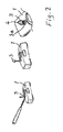
- the sensor unit 1 includes one or more remote thermal sensors 2 and an optic module 3, which has a tubular or cylindrical opening ( Fig. 2 and 4 ) defining an optical observation area, through which the remote thermal sensor 2 monitors the temperature of the desired object. If a wider observation area is desired, as the sensor unit is installed in the vicinity of the object, a Fresnel lens can be used. A normal optic lens can also be used. An accurate defining of the object area is necessary in order to avoid false alarms while still achieving adequate observation sensitivity.
- the detector unit 1 has a receptor space 3a of the optic module 3, to which the optic module 3 is interchangeably attached.
- Fig. 2 illustrates how the optic module can easily be interchanged by lifting it up from the receptor space 3a with the tip of a screwdriver. It can be replaced by pressing into the receptor space 3a another optic module 3, the observation area-defining opening 4 of which is suitable for the installation site and the object to be supervised.
- the opening 4 can be tubular or cylindrical or it can be based on a Fresnel lens.
- the shape of the lens or opening 4 and, respectively, the observation area can also be elliptical, wherein it can supervise a wider area from the ceiling.
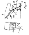
- Fig. 3 shows how the sensor unit 1 of the thermal guard of the stove 10 can be installed at different distances from the stove and at different angles such that the central axis 9a of the observation area 9 defined by the opening 4 is at different angles in relation to the stove 10.
- the distance and angle are greater than when installing to a stove hood fan 12.
- the same sensor unit 1 can be used in both installation sites, when the optic module 3 is interchanged to suit the installation site such that the observation area 9 covers the area of the stove 10.
- the sensor unit 1 is provided with a fastener 5, which engages by a swivel joint 6 with the sensor unit 1 to achieve the desired angle of supervision.
- the fastener 5 can be optionally attached to a stove hood fan 12 or to the ceiling or on a wall 11.
- the optic module 3 of the sensor unit can be a part of an interchangeable protective casing 3b.
- an articulated 7 fastener can be used for attaching the optic module 3 to achieve the desired angle of supervision.
- the joint 7 is a ball joint.
- the same sensor unit 1 may have one or more optic modules 3.
- the circuit board, to which the remote thermal sensor 2 is connected with a pin 13, is marked with reference numeral 14.
- the same sensor unit can be optionally mounted to a stove hood fan 12 or to the ceiling or on a wall 11.
- installation can easily be made at different distances and in different sites by just interchanging the optic module 3.
Landscapes
- Physics & Mathematics (AREA)
- General Physics & Mathematics (AREA)
- Spectroscopy & Molecular Physics (AREA)
- Emergency Management (AREA)
- Business, Economics & Management (AREA)
- Engineering & Computer Science (AREA)
- Chemical & Material Sciences (AREA)
- Combustion & Propulsion (AREA)
- Analytical Chemistry (AREA)
- Mechanical Engineering (AREA)
- General Engineering & Computer Science (AREA)
- Optics & Photonics (AREA)
- Fire-Detection Mechanisms (AREA)
- Fire Alarms (AREA)
- Photometry And Measurement Of Optical Pulse Characteristics (AREA)
- Food Science & Technology (AREA)
- Arrangements For Transmission Of Measured Signals (AREA)
Applications Claiming Priority (1)
| Application Number | Priority Date | Filing Date | Title |
|---|---|---|---|
| FI20155673A FI126188B (fi) | 2015-09-21 | 2015-09-21 | Lämpötilavahdin anturiyksikkö |
Publications (2)
| Publication Number | Publication Date |
|---|---|
| EP3144908A2 true EP3144908A2 (de) | 2017-03-22 |
| EP3144908A3 EP3144908A3 (de) | 2017-10-04 |
Family
ID=56551149
Family Applications (1)
| Application Number | Title | Priority Date | Filing Date |
|---|---|---|---|
| EP16178517.5A Withdrawn EP3144908A3 (de) | 2015-09-21 | 2016-07-08 | Temperaturwächtersensoreinheit |
Country Status (8)
| Country | Link |
|---|---|
| US (1) | US20170082495A1 (de) |
| EP (1) | EP3144908A3 (de) |
| JP (1) | JP2017062773A (de) |
| KR (1) | KR20170034765A (de) |
| CN (1) | CN106546336A (de) |
| AU (1) | AU2016208276A1 (de) |
| CA (1) | CA2935512A1 (de) |
| FI (1) | FI126188B (de) |
Cited By (2)
| Publication number | Priority date | Publication date | Assignee | Title |
|---|---|---|---|---|
| EP3508793B1 (de) * | 2018-01-09 | 2020-09-23 | Safera OY | Ofenschutz mit verwendung eines breitem sichtfeldes |
| WO2021165585A1 (en) * | 2020-02-20 | 2021-08-26 | Safera Oy | Modular stove guard arrangement |
Families Citing this family (5)
| Publication number | Priority date | Publication date | Assignee | Title |
|---|---|---|---|---|
| KR102629641B1 (ko) * | 2021-11-26 | 2024-01-29 | (주)샤픈고트 | 교체형 회전 모듈을 이용한 재난 안전 감지 방법 및 이러한 방법을 수행하는 장치 |
| USD1101014S1 (en) | 2023-05-08 | 2025-11-04 | Lsi Industries, Inc. | Infrared sensor lens |
| USD1061289S1 (en) | 2023-05-08 | 2025-02-11 | Lsi Industries, Inc. | Infrared sensor lens |
| USD1061288S1 (en) | 2023-05-08 | 2025-02-11 | Lsi Industries, Inc. | Infrared sensor lens |
| USD1101831S1 (en) | 2023-05-08 | 2025-11-11 | Lsi Industries, Inc. | Infrared sensor lens |
Citations (5)
| Publication number | Priority date | Publication date | Assignee | Title |
|---|---|---|---|---|
| JPH09113365A (ja) * | 1995-10-16 | 1997-05-02 | Matsushita Electric Ind Co Ltd | 焦電型赤外線センサ |
| CN201757673U (zh) * | 2010-07-21 | 2011-03-09 | 淮南润成科技有限公司 | 矿用被动式热释电红外传感器 |
| US20120200212A1 (en) * | 2011-02-09 | 2012-08-09 | Flir Systems, Inc. | Modular Optical Box |
| CN103512066A (zh) * | 2012-06-29 | 2014-01-15 | 太仓南极风能源设备有限公司 | 自动调速油烟机 |
| US20140084165A1 (en) * | 2012-09-21 | 2014-03-27 | Nest Labs, Inc. | Selectable lens button for a hazard detector and method therefor |
Family Cites Families (19)
| Publication number | Priority date | Publication date | Assignee | Title |
|---|---|---|---|---|
| US3307529A (en) * | 1964-10-23 | 1967-03-07 | Fostoria Fannon Inc | Radiant heater arrangement |
| US4626686A (en) * | 1984-04-09 | 1986-12-02 | Exergen Corporation | Variable field of view heat scanner |
| SE461560B (sv) * | 1988-02-24 | 1990-02-26 | Carl Goesta Ardesjoe | Anordning foer oevervakning av objekt, saasom kokplattor och elektriska spisar, med avseende paa oeverhettning |
| WO1993018494A1 (en) * | 1992-03-11 | 1993-09-16 | The Boeing Company | Thermal condition sensor system for monitoring equipment operation |
| DE29612087U1 (de) * | 1996-07-12 | 1997-11-06 | Giersiepen Gira Gmbh | Video-Überwachungsgerät |
| DE10032319A1 (de) * | 2000-07-04 | 2002-01-17 | Schneider Klaus | Komplett integrierte, drahtlose Funk-Video und Audioübertragungs-Systemeinheit und ferngesteuert drehbare Schwenkmechanik mit steck- und schraubbaren Halterungsvorrichtungen für den direkten Betrieb aus der 220VAC Steckdose und/oder Lampenfassung |
| KR100451237B1 (ko) * | 2002-08-17 | 2004-10-02 | 엘지전자 주식회사 | 써모파일 적외선 센서의 수광각 조절장치 |
| DE10302590B4 (de) * | 2003-01-22 | 2005-04-28 | Giersiepen Gira Gmbh | Kamera, insbesondere Video-Überwachungskamera |
| WO2005062096A1 (en) * | 2003-12-22 | 2005-07-07 | Bae Systems Plc | Waveguide assembly and connector |
| US7004784B2 (en) * | 2004-02-26 | 2006-02-28 | Robert Bosch Gmbh | Tamper detection for security system |
| US7151457B2 (en) * | 2004-03-10 | 2006-12-19 | Riley James A | Detection warning system for caregivers in a home |
| ATE512430T1 (de) * | 2004-04-14 | 2011-06-15 | Bosch Gmbh Robert | Detektor mit scheuklappen |
| WO2005103786A1 (en) * | 2004-04-20 | 2005-11-03 | Deutsch Uk | Waveguide assembly and connector |
| CN201083543Y (zh) * | 2007-09-07 | 2008-07-09 | 常州宝仪机电设备有限公司 | 角度自适应红外扫描测温系统 |
| FI121608B (fi) * | 2008-07-04 | 2011-01-31 | Safera Oy | Liesiturvajärjestelmä |
| CN101349600A (zh) * | 2008-09-08 | 2009-01-21 | 合肥正阳光电科技有限责任公司 | 基于光纤光栅的红外和微波辐射测温传感器 |
| WO2010116233A2 (en) * | 2009-04-09 | 2010-10-14 | Indesit Company S.P.A. | Temperature detector |
| CN103439002A (zh) * | 2013-03-17 | 2013-12-11 | 高清福 | 一种基于智能移动终端的热成像及测温系统 |
| CN104677503A (zh) * | 2013-12-03 | 2015-06-03 | 徐州盛高矿山机械制造有限公司 | 激光熔池实时监控方法 |
-
2015
- 2015-09-21 FI FI20155673A patent/FI126188B/fi active IP Right Grant
-
2016
- 2016-07-08 CA CA2935512A patent/CA2935512A1/en not_active Abandoned
- 2016-07-08 EP EP16178517.5A patent/EP3144908A3/de not_active Withdrawn
- 2016-07-26 AU AU2016208276A patent/AU2016208276A1/en not_active Abandoned
- 2016-08-02 KR KR1020160098324A patent/KR20170034765A/ko not_active Withdrawn
- 2016-08-03 US US15/227,061 patent/US20170082495A1/en not_active Abandoned
- 2016-08-05 JP JP2016155086A patent/JP2017062773A/ja active Pending
- 2016-08-18 CN CN201610803256.5A patent/CN106546336A/zh active Pending
Patent Citations (5)
| Publication number | Priority date | Publication date | Assignee | Title |
|---|---|---|---|---|
| JPH09113365A (ja) * | 1995-10-16 | 1997-05-02 | Matsushita Electric Ind Co Ltd | 焦電型赤外線センサ |
| CN201757673U (zh) * | 2010-07-21 | 2011-03-09 | 淮南润成科技有限公司 | 矿用被动式热释电红外传感器 |
| US20120200212A1 (en) * | 2011-02-09 | 2012-08-09 | Flir Systems, Inc. | Modular Optical Box |
| CN103512066A (zh) * | 2012-06-29 | 2014-01-15 | 太仓南极风能源设备有限公司 | 自动调速油烟机 |
| US20140084165A1 (en) * | 2012-09-21 | 2014-03-27 | Nest Labs, Inc. | Selectable lens button for a hazard detector and method therefor |
Cited By (3)
| Publication number | Priority date | Publication date | Assignee | Title |
|---|---|---|---|---|
| EP3508793B1 (de) * | 2018-01-09 | 2020-09-23 | Safera OY | Ofenschutz mit verwendung eines breitem sichtfeldes |
| US11441845B2 (en) | 2018-01-09 | 2022-09-13 | Safera Oy | Stove guard using a broad field of view |
| WO2021165585A1 (en) * | 2020-02-20 | 2021-08-26 | Safera Oy | Modular stove guard arrangement |
Also Published As
| Publication number | Publication date |
|---|---|
| KR20170034765A (ko) | 2017-03-29 |
| FI126188B (fi) | 2016-08-15 |
| US20170082495A1 (en) | 2017-03-23 |
| EP3144908A3 (de) | 2017-10-04 |
| JP2017062773A (ja) | 2017-03-30 |
| CN106546336A (zh) | 2017-03-29 |
| FI20155673A7 (fi) | 2016-08-15 |
| AU2016208276A1 (en) | 2017-04-06 |
| CA2935512A1 (en) | 2017-03-21 |
Similar Documents
| Publication | Publication Date | Title |
|---|---|---|
| EP3144908A2 (de) | Temperaturwächtersensoreinheit | |
| EP2425410B1 (de) | Detektoren | |
| EP3147880B2 (de) | Überwachungs- und steuerungsverfahren zur verhinderung von schlechter luftqualität und feuer sowie zur ausgabe eins alarms bei einem gefährlichen zustand | |
| US9109805B2 (en) | Range hood with temperature detection and notification | |
| KR20180004800A (ko) | 전기설비용 스마트 퀵 연결장치 | |
| WO2015057073A1 (en) | Kitchen sensor panel and kitchen monitoring system | |
| AU2014221188A1 (en) | Duct detector with remote airflow test capability | |
| KR101114551B1 (ko) | 비접촉 온도 감시 장치 | |
| KR101447528B1 (ko) | Cctv를 이용한 화재 경보 제어 장치 및 시스템 | |
| KR20170090588A (ko) | 전기 판넬 과열 감시 장치 | |
| EP3836863A4 (de) | Katheterablationsvorrichtung mit temperaturüberwachung | |
| KR20200082353A (ko) | 화재 감지장치 및 이의 제어방법 | |
| US10539458B2 (en) | Optical flame detector | |
| US20150322617A1 (en) | Dryer Exhaust Duct Alarm | |
| CN205549294U (zh) | 自巡逻可侦测电启动式自动灭火机器人 | |
| CN203671640U (zh) | 一种气化炉火焰检测装置 | |
| US20060105280A1 (en) | Through a wall combustion detector | |
| KR101010864B1 (ko) | 보안감시용 적외선 열화상 카메라 시스템의 문턱값 능동 설정 장치 및 방법 | |
| KR101662675B1 (ko) | 연기 감지기 | |
| KR20090007165U (ko) | 과열 감지 센서가 구비된 터미널블럭 | |
| CN108036818A (zh) | 一种配电室内电力设备异常定位报警装置 | |
| JP2018063548A (ja) | 作業現場監視装置 | |
| KR20180068094A (ko) | 화재인지 손잡이 | |
| CN102737470A (zh) | 一种厨房用视频安全系统 | |
| KR20210041210A (ko) | 복합형 화재감지기 |
Legal Events
| Date | Code | Title | Description |
|---|---|---|---|
| PUAI | Public reference made under article 153(3) epc to a published international application that has entered the european phase |
Free format text: ORIGINAL CODE: 0009012 |
|
| STAA | Information on the status of an ep patent application or granted ep patent |
Free format text: STATUS: THE APPLICATION HAS BEEN PUBLISHED |
|
| AK | Designated contracting states |
Kind code of ref document: A2 Designated state(s): AL AT BE BG CH CY CZ DE DK EE ES FI FR GB GR HR HU IE IS IT LI LT LU LV MC MK MT NL NO PL PT RO RS SE SI SK SM TR |
|
| AX | Request for extension of the european patent |
Extension state: BA ME |
|
| PUAL | Search report despatched |
Free format text: ORIGINAL CODE: 0009013 |
|
| AK | Designated contracting states |
Kind code of ref document: A3 Designated state(s): AL AT BE BG CH CY CZ DE DK EE ES FI FR GB GR HR HU IE IS IT LI LT LU LV MC MK MT NL NO PL PT RO RS SE SI SK SM TR |
|
| AX | Request for extension of the european patent |
Extension state: BA ME |
|
| RIC1 | Information provided on ipc code assigned before grant |
Ipc: G01J 5/08 20060101ALI20170829BHEP Ipc: F24C 7/08 20060101ALI20170829BHEP Ipc: G01J 5/04 20060101ALI20170829BHEP Ipc: A47J 36/32 20060101ALI20170829BHEP Ipc: G08B 17/12 20060101AFI20170829BHEP Ipc: G08B 17/06 20060101ALI20170829BHEP Ipc: G08B 13/193 20060101ALI20170829BHEP |
|
| STAA | Information on the status of an ep patent application or granted ep patent |
Free format text: STATUS: REQUEST FOR EXAMINATION WAS MADE |
|
| 17P | Request for examination filed |
Effective date: 20180404 |
|
| RBV | Designated contracting states (corrected) |
Designated state(s): AL AT BE BG CH CY CZ DE DK EE ES FI FR GB GR HR HU IE IS IT LI LT LU LV MC MK MT NL NO PL PT RO RS SE SI SK SM TR |
|
| RAP1 | Party data changed (applicant data changed or rights of an application transferred) |
Owner name: INNOHOME OY |
|
| RIN1 | Information on inventor provided before grant (corrected) |
Inventor name: MYLLYMAEKI, MATTI |
|
| STAA | Information on the status of an ep patent application or granted ep patent |
Free format text: STATUS: EXAMINATION IS IN PROGRESS |
|
| 17Q | First examination report despatched |
Effective date: 20210702 |
|
| STAA | Information on the status of an ep patent application or granted ep patent |
Free format text: STATUS: THE APPLICATION IS DEEMED TO BE WITHDRAWN |
|
| 18D | Application deemed to be withdrawn |
Effective date: 20240224 |