EP3144910A1 - Procédé et dispositif de localisation d'un dispositif vestimentaire - Google Patents
Procédé et dispositif de localisation d'un dispositif vestimentaire Download PDFInfo
- Publication number
- EP3144910A1 EP3144910A1 EP16184993.0A EP16184993A EP3144910A1 EP 3144910 A1 EP3144910 A1 EP 3144910A1 EP 16184993 A EP16184993 A EP 16184993A EP 3144910 A1 EP3144910 A1 EP 3144910A1
- Authority
- EP
- European Patent Office
- Prior art keywords
- terminal device
- wearable device
- server
- short range
- range communication
- Prior art date
- Legal status (The legal status is an assumption and is not a legal conclusion. Google has not performed a legal analysis and makes no representation as to the accuracy of the status listed.)
- Granted
Links
Images


Classifications
-
- H—ELECTRICITY
- H04—ELECTRIC COMMUNICATION TECHNIQUE
- H04W—WIRELESS COMMUNICATION NETWORKS
- H04W76/00—Connection management
- H04W76/10—Connection setup
- H04W76/14—Direct-mode setup
-
- H—ELECTRICITY
- H04—ELECTRIC COMMUNICATION TECHNIQUE
- H04W—WIRELESS COMMUNICATION NETWORKS
- H04W4/00—Services specially adapted for wireless communication networks; Facilities therefor
- H04W4/02—Services making use of location information
-
- G—PHYSICS
- G08—SIGNALLING
- G08B—SIGNALLING SYSTEMS, e.g. PERSONAL CALLING SYSTEMS; ORDER TELEGRAPHS; ALARM SYSTEMS
- G08B21/00—Alarms responsive to a single specified undesired or abnormal condition and not otherwise provided for
- G08B21/02—Alarms for ensuring the safety of persons
- G08B21/0202—Child monitoring systems using a transmitter-receiver system carried by the parent and the child
- G08B21/0241—Data exchange details, e.g. data protocol
- G08B21/025—System arrangements wherein the alarm criteria uses absence of reply signal after an elapsed time
-
- G—PHYSICS
- G08—SIGNALLING
- G08B—SIGNALLING SYSTEMS, e.g. PERSONAL CALLING SYSTEMS; ORDER TELEGRAPHS; ALARM SYSTEMS
- G08B21/00—Alarms responsive to a single specified undesired or abnormal condition and not otherwise provided for
- G08B21/02—Alarms for ensuring the safety of persons
- G08B21/0202—Child monitoring systems using a transmitter-receiver system carried by the parent and the child
- G08B21/0241—Data exchange details, e.g. data protocol
- G08B21/0258—System arrangements wherein both parent and child units can emit and receive
-
- G—PHYSICS
- G08—SIGNALLING
- G08B—SIGNALLING SYSTEMS, e.g. PERSONAL CALLING SYSTEMS; ORDER TELEGRAPHS; ALARM SYSTEMS
- G08B21/00—Alarms responsive to a single specified undesired or abnormal condition and not otherwise provided for
- G08B21/02—Alarms for ensuring the safety of persons
- G08B21/0202—Child monitoring systems using a transmitter-receiver system carried by the parent and the child
- G08B21/0269—System arrangements wherein the object is to detect the exact location of child or item using a navigation satellite system, e.g. GPS
-
- G—PHYSICS
- G08—SIGNALLING
- G08B—SIGNALLING SYSTEMS, e.g. PERSONAL CALLING SYSTEMS; ORDER TELEGRAPHS; ALARM SYSTEMS
- G08B21/00—Alarms responsive to a single specified undesired or abnormal condition and not otherwise provided for
- G08B21/02—Alarms for ensuring the safety of persons
- G08B21/0202—Child monitoring systems using a transmitter-receiver system carried by the parent and the child
- G08B21/0277—Communication between units on a local network, e.g. Bluetooth®, piconet, Zigbee®, Wireless Personal Area Networks [WPAN]
-
- H—ELECTRICITY
- H04—ELECTRIC COMMUNICATION TECHNIQUE
- H04L—TRANSMISSION OF DIGITAL INFORMATION, e.g. TELEGRAPHIC COMMUNICATION
- H04L67/00—Network arrangements or protocols for supporting network services or applications
- H04L67/50—Network services
- H04L67/52—Network services specially adapted for the location of the user terminal
-
- H—ELECTRICITY
- H04—ELECTRIC COMMUNICATION TECHNIQUE
- H04W—WIRELESS COMMUNICATION NETWORKS
- H04W4/00—Services specially adapted for wireless communication networks; Facilities therefor
- H04W4/80—Services using short range communication, e.g. near-field communication [NFC], radio-frequency identification [RFID] or low energy communication
-
- H—ELECTRICITY
- H04—ELECTRIC COMMUNICATION TECHNIQUE
- H04W—WIRELESS COMMUNICATION NETWORKS
- H04W64/00—Locating users or terminals or network equipment for network management purposes, e.g. mobility management
Definitions
- the present disclosure generally relates to computer technologies, and more particularly, to a method and devices for locating a wearable device.
- wristbands may have a loss-prevention function.
- a wristband worn by a child may be connected with a terminal device of a parent of this child via wireless communications such as Bluetooth.
- wireless communications such as Bluetooth.
- the Bluetooth connection is disconnected, and the terminal device of the parent will output alarms.
- such a wristband does not help the parent to quickly find the child in crowded locations.
- the present disclosure provides a method and a device for locating a wearable device in order to solve the problem that if a child with a wristband gets separated from his/her parent and Bluetooth connection is disconnected, the wristband is not helpful for quickly finding the child at crowded positions.
- a method for locating a wearable device including:
- the notification message includes identity information of a user who uses the wearable device and a distress signal, and the notification message is further configured to instruct the at least one second terminal device to report to the server location information of the at least one second terminal device and the identity information.
- the method further includes:
- the broadcasting the notification message includes:
- the short range communication connection includes a Bluetooth connection
- a method for locating a wearable device including:
- the notification message includes identity information of a user who uses the wearable device and a distress signal, and the method further includes:
- the method before the receiving, by the second terminal device, the notification message broadcast by the wearable device, the method further includes:
- the short range communication connection includes a Bluetooth connection
- the establishing, by the second terminal device, the short range communication connection with the wearable device includes:
- a method for obtaining location information including:
- the method further includes:
- a wearable device including:
- the wearable device further includes:
- the sending module includes:
- the short range communication connection includes a Bluetooth connection
- the wearable device further includes:
- a second terminal device including:
- the notification message includes identity information of a user who uses the wearable device and a distress signal
- the sending module is further configured to report location information of the terminal device itself and the identity information to the server.
- the terminal device further includes:
- the short range communication connection includes a Bluetooth connection
- the communication module includes:
- a server including:
- the server further includes:
- a wearable device including:
- a second terminal device including:
- a server including:
- a computer program which when executing on a processor, performs any one of the above methods.
- the wearable device After a wearable device is disconnected from a first terminal device, the wearable device broadcasts a notification message. After a short range communication connection between the wearable device and surrounding second terminal devices are established, the second terminals report the identity of the connected wearable device to a server, and the server locates the location of the wearable device according to the second terminals to determine the location information of the wearable device. Thus, it is guaranteed that after the first terminal device is disconnected from the wearable device, the location of the wearable device can be quickly determined.
- the wearable device may notify surrounding second terminal devices of the identity information of the wearable device and distress information, and the second terminal devices report the identity information of the wearable device and the location information of the second terminal devices to the server, so that the server can quickly locate the wearable device according to multiple pieces of location information.
- the wearable device may obtain identity information of a user who uses the wearable device so that the wearable device can send the distress information to surrounding second devices when the connection is disconnected.
- the wearable device when the wearable device seeks help after the connection is disconnected, the wearable device can send broadcast information via any manner such as Bluetooth, wireless networks, or base stations to extend the application scenario without limiting to a single help seeking manner.
- the server can locate the wearable device more quickly and accurately.
- the wearable device is connected with the terminal device via Bluetooth so as to reduce costs.
- second terminal devices when second terminal devices receive the notification message sent from a nearby wearable device, the second terminal devices establish a connection with the wearable device, and report the connection with the wearable device, so that the server can locate the wearable device according to these second terminal devices and thereby determine the location of the wearable device.
- the second terminal devices obtain the identity information of the wearable device and send the identity information and the location information of the second terminal devices to the server, so that the server can quickly locate the wearable device according to multiple pieces of location information.
- the second terminal devices receive instructions from the server to turn on short range communication detection.
- the server controls the second terminal devices surrounding the first terminal device to help the server to find the wearable device and thereby to locate the wearable device.
- the wearable device is connected with the terminal device via Bluetooth so as to reduce costs.
- the first terminal device reports the location information of itself and distress information to notify the server that the first terminal device is disconnected from the wearable device.
- the server sends a request for turning on monitoring to second terminal devices within a preset range of the first terminal device according to the location information.
- the server controls the surrounding terminal devices to find the wearable device, and thereby can locate the wearable device quickly and efficiently.
- the second terminal devices report the location information of themselves, and thus the server can determine the location of the wearable device more accurately and quickly according to the location information of the multiple second terminal devices.
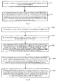
- Fig. 1 is a flowchart showing a first embodiment of a method for locating a wearable device according to an exemplary embodiment of the present disclosure.
- the method for locating a wearable device is mainly applied at a wearable device side.
- the wearable device may be smart devices capable of being directly worn such as wristbands or watches. After a first terminal device is disconnected from the wearable device, the wearable device can be quickly located by other surrounding terminal devices.
- the method for locating a wearable device include the following steps:
- step S101 the wearable device determines whether a short range communication connection with a first terminal device is disconnected.
- the wearable device itself has a detection function, and the disconnection from the previously connected first terminal device can be detected. That is, bidirectional detection function is started when the wearable device is connected with the first terminal device.
- the short range communication connection refers to a wireless communication approach which is available only within a certain distance range. For example, Bluetooth connection, Near Field Communication (NFC) and the like.
- step S102 if the wearable device determines that the short range communication connection with the first terminal device is disconnected, the wearable device broadcasts a notification message for instructing at least one second terminal device to establish a short range communication connection with the wearable device and instructing the at least one second terminal device to send a connection notification to a server so that the server locates the wearable device according to the at least one second terminal device.
- the wearable device after the wearable device is disconnected from the previously connected first terminal device, i.e., the wearable device detects the disconnection information, the wearable device broadcasts a notification message using Bluetooth, or other radio information such as wireless local area networks, or base station signals.
- the notification message is configured to notify second terminal devices within a certain range from the wearable device that the wearable device is disconnected from the previously connected terminal device, and request to establish a short range communication connection with the second terminal devices.
- the notification message is further configured to instruct the second terminal devices to notify the server after establishing a connection with the wearable device, so that the server can obtain the locations of the second terminal devices to quickly locate the wearable device.
- the notification message includes identity information of a user who uses the wearable device and also optionally a distress signal
- the notification message is further configured to instruct the at least one second terminal device to report to the server location information of the at least one second terminal device and the identity information.
- the second terminal devices can obtain information regarding the locations where the second terminal devices are by performing location process via a Global Positioning System (GPS), and report the identity information of the wearable device and the information regarding the locations where the second terminal devices are to the server, so that the server can locate the missing wearable device according to the location information of the second terminal devices which establish a short range communication connection with the wearable device corresponding to the identity information. Then, the server can obtain the location information of the wearable device to quickly find the wearable device.
- GPS Global Positioning System
- the wearable device After a wearable device is disconnected from a first terminal device, the wearable device broadcasts a notification message. After a short range communication connection between the wearable device and surrounding second terminal devices are established, the second terminals reports the identity of the connected wearable device to a server, and the server locates the location of the wearable device according to the second terminals to determine the location information of the wearable device.
- the server locates the location of the wearable device according to the second terminals to determine the location information of the wearable device.
- Fig. 2 is a flowchart showing a second embodiment of a method for locating a wearable device according to an exemplary embodiment. As shown in Fig. 2 , on the basis of the embodiment as shown in Fig. 1 , the method for locating a wearable device according to another exemplary embodiment includes the following steps.
- step S201 the wearable device obtains identity information of a user who uses the wearable device.
- the wearable device needs to obtain identity of the user who uses the wearable device, for example, the name, the guardian, contact numbers, home address, and the like.
- identity of the user who uses the wearable device for example, the name, the guardian, contact numbers, home address, and the like.
- the obtaining of the information at least includes the following two approaches:
- the wearable device receives the identity information sent from the first terminal device, and locally stores the identity information. For example, a user can input related identity information by the first terminal device and send the identity information to the wearable device for storage.
- the wearable device collects the identity information recorded by a user, and locally stores the identity information.
- the wearable device itself has an input device such as a touch screen, a microphone or a display and the like, and thus related identity information can be recorded by the wearable device itself.
- step S202 the wearable device determines whether the short range communication connection with the first terminal device is disconnected.
- step S203 if the wearable device determines that the short range communication connection with the first terminal device is disconnected, the wearable device broadcasts a notification message which includes the identity information of the user who uses the wearable device and a distress signal.
- the notification message is further configured to instruct the at least one second terminal device to report to the server location information of the at least one second terminal device and the identity information.
- the wearable device after the wearable device determines that the short range communication connection between the wearable device and the first terminal device is disconnected, the wearable device broadcasts the notification message to surrounding devices.
- Specific implementation methods include at least the follows.
- the wearable device broadcasts the notification message via Bluetooth; or the wearable device broadcasts the notification message via a wireless local area network; or the wearable device broadcasts the notification message via a base station signal.
- the second terminal devices can turn on the short range communication connection in a certain time internal. After receiving the notification message, if the second terminal devices agree with the connection, the second terminal devices establish a connection with the wearable device, and then notify the server of the location information and the identity information so that the server can locate the wearable device.
- the short range communication connection includes but not limited to Bluetooth connection
- the wearable device can establish a Bluetooth connection with the first terminal device. After the wearable device founds that the Bluetooth connection is disconnected, the wearable device can establish a Bluetooth connection with surrounding second terminal devices and transmits related information.
- the wearable device needs to obtain identity information of a user who uses the wearable device so that the wearable device can send the distress information to surrounding second devices when the connection is disconnected.
- the wearable device seeks help after the connection is disconnected, the wearable device can send broadcast information via any manner such as Bluetooth, wireless networks, or base stations to extend the application scenario without limiting to a single help seeking manner.
- the server can locate the wearable device more quickly and accurately. It is preferable that the wearable device is connected with the terminal device via Bluetooth so as to reduce costs.
- Fig. 3 is a flowchart showing a third embodiment of a method for locating a wearable device according to an exemplary embodiment. As shown in Fig. 3 , the method for locating a wearable device is mainly applied at a second terminal device side.
- the second terminal device can be terminal devices having a short range communication function such as a mobile phone, a laptop, a tablet computer and the like.
- the method for locating a wearable device may be implemented by the following steps.
- the second terminal device receives a notification message broadcast by the wearable device.
- the notification message is configured to instruct the second terminal device to establish a short range communication connection with the wearable device and instruct the second terminal device to report a connection notification to a server.
- step S302 the second terminal device establishes the short range communication connection with the wearable device, and sends the connection notification to the server, so that the server locates the wearable device according to each second terminal device.
- the connection notification is configured to indicate that the second terminal device has established the short range communication connection with the wearable device.
- the second terminal devices are terminal devices which surround the wearable device and agree with joining the function. In a range where short range communication is available, if a wearable device is disconnected from a previously connected first terminal device, the second terminal devices receive the notification message broadcast by the wearable device, and send a connection notification to the server after agreeing with establishing a connection with the wearable device.
- connection notification may carry the identity of the wearable device so that the server can distinguish multiple wearable devices according to identities and locate a wearable device which needs to be located.
- second terminal devices After receiving a notification message sent from a nearby wearable device, second terminal devices establish a connection with the wearable device, and report to the server that the second terminal devices establish a connection with the wearable device, so that the server locates the wearable according to these second terminal device and determine the location of the wearable device. Consequently, a missing wearable device can be quickly located.
- Fig. 4 is a flowchart of a fourth embodiment of a method for locating a wearable device according to a wearable device. As shown in Fig. 4 , the present embodiment is performed by a second terminal device. On the basis of the embodiment as shown in Fig. 3 , the method for locating a wearable device may be implemented by the following steps.
- step S401 the second terminal device receives a request for turning on a monitoring function sent from a server.
- step S402 the second terminal device turns on a short range communication detection function according to the request for turning on a monitoring function so as to establish a short range communication connection with a wearable device.
- the second terminal device receives a notification message broadcast by the wearable device.
- the notification message is configured to instruct the second terminal device to establish a short range communication connection with the wearable device and instruct the second terminal device to report a connection notification to a server.
- step S404 the second terminal device establishes the short range communication connection with the wearable device, and sends the connection notification to the server.
- step S405 the second terminal device reports location information of the second terminal device itself and the identity information to the server.
- the first terminal device after the first terminal device detects that the first terminal device is disconnected from the wearable device, the first terminal obtains the location information of the itself, and sends the location information and/or base station information of the itself and a request for locating the wearable device to a server.
- the server After receiving the request, the server sends a request for turning on a monitoring function to second terminal devices such as mobile phones surrounding the first terminal device to request help to find the wearable device. After the surrounding second terminal device agree with turning on the function, the second terminal devices turn on related detection function and establish a short range communication connection with the wearable device.
- the second terminal devices obtain the location information of themselves using a GPS function.
- the second terminal device reports the location information of themselves and the identity information to the server, and the server can locate the wearable device according to the multiple pieces of location information, and can notify the first terminal device so as to find the wearable device.
- the short range communication connection includes but not limited to Bluetooth connection.
- the connection established between the second terminal devices and the wearable device is a Bluetooth connection.
- the previous connection between the wearable device and the first terminal device may also be a Bluetooth connection.
- the second terminal devices receive instructions from the server to turn on short range communication detection.
- the server controls the second terminal devices surrounding the first terminal device to help the server to find the wearable device.
- the wearable device can be located using the location information of the second terminal devices which surround the first terminal device and establish a connection with the wearable device. It is preferable that the connection between the terminal device and the wearable device is a Bluetooth connection to reduce costs.
- Fig. 5 is a flowchart showing a fifth embodiment of a method for locating a wearable device according to an exemplary embodiment. As shown in Fig. 5 , the method for locating a wearable device is mainly applied at a server side. Specifically, the method for locating a wearable device can be implemented by the following steps.
- a server receives location information and distress information reported by a first terminal device.
- the distress information indicates that the first terminal device is disconnected from a wearable device.
- step S502 the server sends a request for turning on a monitoring function to at least one second terminal device within a preset range from the first terminal device according to the location information, so that the at least one second terminal device turns on a short range communication detection function to establish the short range communication connection with the wearable device.
- step S503 the server receives location information of the at least one second terminal device and identity information of a user who uses the wearable device reported by the at least one second terminal device, and locates the wearable device according to the location information reported by each of the at least one second terminal device.
- the server receives the location information of the first terminal device itself and distress information requesting for locating the wearable device sent from the first terminal device.
- the first terminal device notifies the server that the first terminal is disconnected from the wearable.
- the server sends a request for turning on monitoring to second terminal devices within a preset range surrounding the first terminal device, and then the second terminal devices report the location information of themselves. By controlling the surrounding second terminal devices to find the wearable device, the server can accurately and efficiently locate the wearable device.
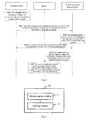
- Fig. 6 is a flowchart showing an interaction example of a method for locating a wearable device according to an exemplary embodiment.
- Fig. 6 shows the interactions among a wearable device, second terminal devices and a server.
- the method for locating a wearable device is implemented by the following steps.
- step S601 the wearable device determines whether the connection with the first terminal device is disconnected.
- step S602 after the wearable device determines that the connection with the first terminal device is disconnected, the wearable device broadcasts a notification message.
- step S603 the second terminal devices receive the notification message and turn on a short range communication detection function.
- step S604 the second terminal devices establish a short range communication connection with the wearable device.
- step S605 the second terminal devices report a connection notification, location information and identity information of the wearable device to a server.
- step S606 the server locates the wearable device according to the location information of the multiple second terminal devices, and obtains the location information of the wearable device.
- the first terminal can repot the location information of itself and a locating request to the server to request for locating the wearable device.
- the server can notify the first terminal device so that the first terminal device can find the wearable device back.
- the technical solutions may be used for finding lost wearable devices, or for finding lost children or old persons by the wearable devices after the children or the old persons get lost.
- the wearable device mentioned in the technical solutions takes forms of portable accessories which have some computation functions and are connectable to mobile phones and other types of terminals.
- the mainstream product forms include watch type products with wrist as a support (for example, watches, wristbands, bracelets, and the like), shoes type products with foot as a support (for example, shoes, stockings or future products worn on foot), and glasses type products with head as a support (for example, glasses, helmets, head bands, and the like).
- Non-mainstream product forms include smart clothing, schoolbags, walking sticks, fashion accessories and the like. The present disclosure does not impose specific limitations on applications.
- a child is worn with a wristband which establishes a Bluetooth connection with a mobile phone of a parent of the child.
- the wristband When the wristband establishes the Bluetooth connection with the mobile phone, bi-directional detections are turned on, i.e., after the Bluetooth connection is disconnected, the wristband can also detect the disconnection.
- the wristband broadcasts a notification message via Bluetooth or other radio signals such as WIFI. If mobile phones surrounding the wristband agree with joining the function, the mobile phones turn on the Bluetooth scanning in a certain internal to establish a Bluetooth with the wristband, and report to a server that the mobile phones establish a connection with an identified wristband.
- the server can locate the wristband according to these mobile phones.
- the mobile phone of the parent after the mobile phone of the parent detects that the Bluetooth connection with the wristband is disconnected, the mobile phone automatically reports the location information of the mobile phone itself and the base station information and the like to the server.
- the server automatically controls surrounding mobile phones or mobile phone within nearby base stations to turn on a Bluetooth monitoring function. If the surrounding mobile phones agree with this function and establish a Bluetooth connection with the wristband, these mobile phones promptly report the GPS information of themselves and the information of the wristband of this child to the server.
- the server locates the wristband according to the wristband information and GPS information reported by these mobile phones.
- the wearable device itself or the server triggers the terminal devices surrounding the wearable device to enter into a monitoring mode to monitor the information broadcast by the wearable device.
- the surrounding terminal devices establish a connection dynamically, and report the location information to the server.
- the server locates the wearable wristband to obtain the location information so as to help to quickly find the wearable device. It is preferable to use a Bluetooth connection to reduce costs.
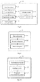
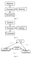
- Fig. 7 is a block diagram showing a first embodiment of a wearable device according to an exemplary embodiment.
- the wearable device 10 includes a determination module 11 and a sending module 12.
- the determination module 11 is configured to determine whether a short range communication connection with a first terminal device is disconnected.
- the sending module 12 is configured to, if the determination module 11 determines that the short range communication connection with the first terminal device is disconnected, broadcast a notification message for instructing at least one second terminal device to establish a short range communication connection with the wearable device and instructing the at least one second terminal device to send a connection notification to a server so that the server locates the wearable device according to the at least one second terminal device.
- Fig. 8 is a second embodiment of a wearable device according to an exemplary embodiment.
- the wearable device 10 may further include a receiving module 13 and a first storage module 14, or a collection module 15 and a second storage module 16.
- the receiving module 13 is configured to receive identity information sent from the first terminal device.
- the first storage module 14 is configured to locally store the identity information.
- the collection module 15 is configured to collect the identity information recorded by a user.
- the second storage module 16 is configured to locally store the identity information.
- the notification message incudes the identity information of a user who uses the wearable device and a distress signal, and the notification message is further configured to instruct the at least one second terminal device to report to the server location information of the at least one second terminal device and the identity information.
- Fig. 9 is a block diagram showing a third embodiment of a wearable device according to an exemplary embodiment.
- the sending module 12 in the wearable device 10 includes a first sending unit 121, a second sending unit 122 or a third sending unit 123.
- the first sending unit 121 is configured to broadcast the notification message via Bluetooth.
- the second sending unit 121 is configured to broadcast the notification message via a wireless local area network.
- the third sending unit 123 is configured to broadcast the notification message via a base station signal.
- Fig. 10 is a block diagram showing a fourth embodiment of a wearable device according to an exemplary embodiment.
- the short range communication connection includes a Bluetooth connection
- the wearable device 10 further includes a Bluetooth communication module 17 configured to establish the Bluetooth connection with the first terminal device.
- Fig. 11 is a block diagram showing a first embodiment of a terminal device according to an exemplary embodiment.
- the terminal device 20 includes a first receiving module 21, a communication module 22 and a sending module 23.
- the first receiving module 21 is configured to receive a notification message broadcast by a wearable device, wherein the notification message is configured to instruct the terminal device to establish a short range communication connection with the wearable device and instruct the terminal device to report a connection notification to a server.
- the communication module 22 is configured to establish the short range communication connection with the wearable device.
- the sending module 23 is configured to send the connection notification to the server, so that the server locates the wearable device according to each second terminal device, wherein the connection notification is configured to indicate that the second terminal device has established the short range communication connection with the wearable device.
- the notification message includes identity information of a user who uses the wearable device and a distress signal
- the sending module is further configured to report location information of the terminal device itself and the identity information to the server.
- Fig. 12 is a block diagram showing a second embodiment of a terminal device according to an exemplary embodiment.
- the terminal device 20 further includes a second receiving module 24 and a processing module 25.
- the second receiving module 24 is configured to a request for turning on a monitoring function sent from the server.
- the processing module 25 is configured to turn on a short range communication detection function according to the request for turning on the monitoring function so that the communication module establishes the short range communication connection with the wearable device.
- Fig. 13 is a block diagram showing a third embodiment of a terminal device according to an exemplary embodiment.
- the short range communication connection includes a Bluetooth connection
- the communication module 22 includes a Bluetooth communication unit 221 configured to establish the Bluetooth connection with the wearable device.
- Fig. 14 is a block diagram showing a first embodiment of a server according to an exemplary embodiment.
- the server 30 includes a first receiving module 31 and a sending module 32.
- the first receiving module 31 is configured to receive location information and distress information reported by a first terminal device, wherein the distress information indicates that the first terminal device is disconnected from a wearable device.
- the sending module 32 is configured to send a request for turning on a monitoring function to at least one second terminal device within a preset range from the first terminal device according to the location information, so that the at least one second terminal device turns on a short range communication detection function to establish the short range communication connection with the wearable device.
- Fig. 15 is a block diagram showing a second embodiment of a server according to an exemplary embodiment.
- the server 30 further includes a second receiving module 33 and a processing module 34.
- the second receiving module 33 is configured to receive location information of the at least one second terminal device and identity information of a user who uses the wearable device reported by the at least one second terminal device.
- the processing module 34 is configured to locate the wearable device according to the location information reported by each of the at least one second terminal device.
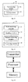
- Fig. 16 is a block diagram showing a physical body of a wearable device according to an exemplary embodiment. Referring to Fig. 16 , the wearable device can be specifically implemented as including:
- Fig. 17 is a block diagram showing a physical body of a terminal device according to an exemplary embodiment.
- the terminal device can be specifically implemented as including:
- Fig. 18 is a block diagram showing a physical body of a server according to an exemplary embodiment.
- the server can be specifically implemented as including:
- the processor may be a Central Processing Unit (CPU), or may be other general-purpose processor, Digital Signal Processor (DSP), Application Specific Integrated Circuit (ASIC), and the like.
- the general-purpose processor may be a microprocessor or any common processor.
- the above memory may be a Read Only Memory (ROM), a Random Access Memory (RAM), a flash, a hard disk, or a solid state hard disk.
- Fig. 19 is a schematic diagram showing a system for locating a wearable device according to an exemplary embodiment.
- the system for locating a wearable device includes a wearable device, a server and at least one second terminal device.
- the wearable device is configured to:
- Each of the second terminal devices is configured to:
- the server is configured to:
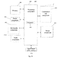
- Fig. 20 is a block diagram showing a wearable device 600 according to an exemplary embodiment.
- the wearable device 600 may be a smart watch, a wristband, wearable exercise equipment or wearable medical device and the like.
- the wearable device 600 may include one or more of the following components: a processing component 602, a memory 604, a power component 606, a sensor component 614, and a communication component 616.
- the wearable device 600 may include a multimedia component 608, an audio component 610, an input/output (I/O) interface 612 and the like.
- the processing component 602 typically controls overall operations of the wearable device 600, such as the operations associated with display, data communications, multimedia operations, and recording operations.
- the processing component 602 may include one or more processors 620 to execute instructions to perform all or part of the steps in the above described methods.
- the processing component 602 may include one or more modules which facilitate the interaction between the processing component 602 and other components.
- the processing component 602 may include a multimedia module to facilitate the interaction between the multimedia component 608 and the processing component 602.
- the memory 604 is configured to store various types of data to support the operation of the wearable device 600. Examples of such data include instructions for any applications or methods operated on the wearable device 600, various data, messages, pictures, video, etc.
- the memory 604 may be implemented using any type of volatile or non-volatile memory devices, or a combination thereof, such as a static random access memory (SRAM), an electrically erasable programmable read-only memory (EEPROM), an erasable programmable read-only memory (EPROM), a programmable read-only memory (PROM), a read-only memory (ROM), a magnetic memory, a flash memory, a magnetic or optical disk.
- SRAM static random access memory
- EEPROM electrically erasable programmable read-only memory
- EPROM erasable programmable read-only memory
- PROM programmable read-only memory
- ROM read-only memory
- magnetic memory a magnetic memory
- flash memory a flash memory
- magnetic or optical disk a magnetic or optical
- the power component 606 provides power to various components of the wearable device 600.
- the power component 606 may include a power management system, one or more power sources, and any other components associated with the generation, management, and distribution of power in the wearable device 600.
- the multimedia component 608 includes a screen providing an output interface between the wearable device 600 and the user.
- the screen may include a liquid crystal display (LCD) and a touch panel (TP). If the screen includes the touch panel, the screen may be implemented as a touch screen to receive input signals from the user.
- the touch panel includes one or more touch sensors to sense touches, swipes, and gestures on the touch panel. The touch sensors may not only sense a boundary of a touch or swipe action, but also sense a period of time and a pressure associated with the touch or swipe action.
- the audio component 610 is configured to output and/or input audio signals.
- the audio component 610 includes a microphone ("MIC") configured to receive an external audio signal when the electronic device 600 is in an operation mode, such as a call mode, a recording mode, and a voice recognition mode.
- the received audio signal may be further stored in the memory 604 or transmitted via the communication component 616.
- the audio component 610 further includes a speaker to output audio signals.
- the I/O interface 612 provides an interface between the processing component 602 and peripheral interface modules, such as a keyboard, a click wheel, buttons, and the like.
- the sensor component 614 includes one or more sensors to provide status assessments of various aspects of the wearable device 600. For instance, the sensor component 614 may detect an open/closed status of the wearable device 600, relative positioning of components, e.g., the display and the keypad, of the wearable device 600, a change in position of the wearable device 600 or a component of the wearable device 600, a presence or absence of user contact with the wearable device 600, an orientation or an acceleration/deceleration of the wearable device 600, and a change in temperature of the wearable device 600.
- the sensor component 614 may include a proximity sensor configured to detect the presence of nearby objects without any physical contact.
- the sensor component 614 may also include a light sensor, such as a CMOS or CCD image sensor, for use in imaging applications.
- the sensor component 614 may also include an accelerometer sensor, a gyroscope sensor, a magnetic sensor, a pressure sensor, or a temperature sensor.
- the communication component 616 is configured to facilitate communication, wired or wirelessly, between the wearable device 600 and other devices.
- the wearable device 600 can access a wireless network based on a communication standard, such as WiFi, 2G, or 3G, or a combination thereof.
- the communication component 616 receives a broadcast signal or broadcast associated information from an external broadcast management system via a broadcast channel.
- the communication component 616 further includes a near field communication (NFC) module to facilitate short-range communications.
- the NFC module may be implemented based on a radio frequency identification (RFID) technology, an infrared data association (IrDA) technology, an ultra-wideband (UWB) technology, a Bluetooth (BT) technology, and other technologies.
- RFID radio frequency identification
- IrDA infrared data association
- UWB ultra-wideband
- BT Bluetooth
- the wearable device 600 may be implemented with one or more application specific integrated circuits (ASICs), digital signal processors (DSPs), digital signal processing devices (DSPDs), programmable logic devices (PLDs), field programmable gate arrays (FPGAs), controllers, micro-controllers, microprocessors, or other electronic components, for performing the above described methods.
- ASICs application specific integrated circuits
- DSPs digital signal processors
- DSPDs digital signal processing devices
- PLDs programmable logic devices
- FPGAs field programmable gate arrays
- controllers micro-controllers, microprocessors, or other electronic components, for performing the above described methods.
- non-transitory computer-readable storage medium including instructions, such as included in the memory 604, executable by the processor 620 in the wearable device 600, for performing the above-described methods.
- the non-transitory computer-readable storage medium may be a ROM, a RAM, a CD-ROM, a magnetic tape, a floppy disc, an optical data storage device, and the like.
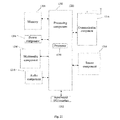
- Fig. 21 is a block diagram showing a terminal device 1200 according to an exemplary embodiment.
- the terminal device 1200 may be a device capable of accessing networks such as a mobile phone, a computer, a digital broadcast terminal, a messaging device, a gaming console, a tablet, a medical device, exercise equipment, a smart home device, a smart home appliance, and the like.
- the terminal device 1200 may include one or more of the following components: a processing component 1202, a memory 1204, a power component 1206, a multimedia component 1208, an audio component 1210, an input/output (I/O) interface 1212, a sensor component 1214, and a communication component 1216.
- a processing component 1202 a memory 1204, a power component 1206, a multimedia component 1208, an audio component 1210, an input/output (I/O) interface 1212, a sensor component 1214, and a communication component 1216.
- the processing component 1202 typically controls overall operations of the terminal device 1200, such as the operations associated with display, telephone calls, data communications, multimedia operations, and recording operations.
- the processing component 1202 may include one or more processors 1220 to execute instructions to perform all or part of the steps in the above described methods.
- the processing component 1202 may include one or more modules which facilitate the interaction between the processing component 1202 and other components.
- the processing component 802 may include a multimedia module to facilitate the interaction between the multimedia component 1208 and the processing component 1202.
- the memory 1204 is configured to store various types of data to support the operation of the terminal device 1200. Examples of such data include instructions for any applications or methods operated on the terminal device 800, various data, messages, pictures, video, etc.
- the memory 1204 may be implemented using any type of volatile or non-volatile memory devices, or a combination thereof, such as a static random access memory (SRAM), an electrically erasable programmable read-only memory (EEPROM), an erasable programmable read-only memory (EPROM), a programmable read-only memory (PROM), a read-only memory (ROM), a magnetic memory, a flash memory, a magnetic or optical disk.
- SRAM static random access memory
- EEPROM electrically erasable programmable read-only memory
- EPROM erasable programmable read-only memory
- PROM programmable read-only memory
- ROM read-only memory
- magnetic memory a magnetic memory
- flash memory a flash memory
- magnetic or optical disk a magnetic or optical disk
- the power component 1206 provides power to various components of the terminal device 1200.
- the power component 1206 may include a power management system, one or more power sources, and any other components associated with the generation, management, and distribution of power in the terminal device 1200.
- the multimedia component 1208 includes a screen providing an output interface between the terminal device 800 and the user.
- the screen may include a liquid crystal display (LCD) and a touch panel (TP). If the screen includes the touch panel, the screen may be implemented as a touch screen to receive input signals from the user.
- the touch panel includes one or more touch sensors to sense touches, swipes, and gestures on the touch panel. The touch sensors may not only sense a boundary of a touch or swipe action, but also sense a period of time and a pressure associated with the touch or swipe action.
- the audio component 1210 is configured to output and/or input audio signals.
- the audio component 1210 includes a microphone ("MIC") configured to receive an external audio signal when the terminal device 1200 is in an operation mode, such as a call mode, a recording mode, and a voice recognition mode.
- the received audio signal may be further stored in the memory 1204 or transmitted via the communication component 1216.
- the audio component 1210 further includes a speaker to output audio signals.
- the I/O interface 1212 provides an interface between the processing component 1202 and peripheral interface modules, such as a keyboard, a click wheel, buttons.
- the sensor component 1214 includes one or more sensors to provide status assessments of various aspects of the terminal device 1200. For instance, the sensor component 1214 may detect an open/closed status of the terminal device 1200, relative positioning of components, e.g., the display and the keypad, of the terminal device 1200, a change in position of the terminal device 1200 or a component of the terminal device 1200, a presence or absence of user contact with the terminal device 1200, an orientation or an acceleration/deceleration of the terminal device 1200, and a change in temperature of the terminal device 1200.
- the sensor component 1214 may include a proximity sensor configured to detect the presence of nearby objects without any physical contact.
- the sensor component 1214 may also include a light sensor, such as a CMOS or CCD image sensor, for use in imaging applications.
- the sensor component 1214 may also include an accelerometer sensor, a gyroscope sensor, a magnetic sensor, a pressure sensor, or a temperature sensor.
- the communication component 1216 is configured to facilitate communication, wired or wirelessly, between the terminal device 1200 and other devices.
- the terminal device 1200 can access a wireless network based on a communication standard, such as WiFi, 2G, or 3G, or a combination thereof.
- the communication component 1216 receives a broadcast signal or broadcast associated information from an external broadcast management system via a broadcast channel.
- the communication component 1216 further includes a near field communication (NFC) module to facilitate short-range communications.
- the NFC module may be implemented based on a radio frequency identification (RFID) technology, an infrared data association (IrDA) technology, an ultra-wideband (UWB) technology, a Bluetooth (BT) technology, and other technologies.
- RFID radio frequency identification
- IrDA infrared data association
- UWB ultra-wideband
- BT Bluetooth
- the terminal device 1200 may be implemented with one or more application specific integrated circuits (ASICs), digital signal processors (DSPs), digital signal processing devices (DSPDs), programmable logic devices (PLDs), field programmable gate arrays (FPGAs), controllers, micro-controllers, microprocessors, or other electronic components, for performing the above described methods.
- ASICs application specific integrated circuits
- DSPs digital signal processors
- DSPDs digital signal processing devices
- PLDs programmable logic devices
- FPGAs field programmable gate arrays
- controllers micro-controllers, microprocessors, or other electronic components, for performing the above described methods.
- non-transitory computer-readable storage medium including instructions, such as included in the memory 1204, executable by the processor 1220 in the terminal device 1200, for performing the above-described methods.
- the non-transitory computer-readable storage medium may be a ROM, a RAM, a CD-ROM, a magnetic tape, a floppy disc, an optical data storage device, and the like.
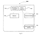
- Fig. 22 is a block diagram showing a server 1900 according to an exemplary embodiment.
- the server 1900 includes a processing component 1922 that further includes one or more processors, and memory resources represented by a memory 1932 for storing instructions executable by the processing component 1922, such as application programs.
- the application programs stored in the memory 1932 may include one or more modules each corresponding to a set of instructions.
- the processing component 1922 is configured to execute the instructions to perform the solutions for locating a wearable device at the server side.
- the server 1900 may also include a power component 1926 configured to perform power management of the server 1900, wired or wireless network interface(s) 1950 configured to connect the server 1900 to a network, and an input/output (I/O) interface 1958.
- the server 1900 may operate based on an operating system stored in the memory 1932, such as Windows Server TM , Mac OS X TM , Unix TM , Linux TM , FreeBSD TM , or the like.
- modules are referred to in apparatus embodiments for carrying out various steps of the described method(s) it will be understood that these modules may be implemented in hardware, in software, or a combination of the two.
- the modules When implemented in hardware, the modules may be implemented as one or more hardware modules, such as one or more application specific integrated circuits.
- the modules When implemented in software, the modules may be implemented as one or more computer programs that are executed on one or more processors.
Landscapes
- General Health & Medical Sciences (AREA)
- Health & Medical Sciences (AREA)
- Child & Adolescent Psychology (AREA)
- Engineering & Computer Science (AREA)
- Computer Networks & Wireless Communication (AREA)
- Physics & Mathematics (AREA)
- Business, Economics & Management (AREA)
- Emergency Management (AREA)
- General Physics & Mathematics (AREA)
- Signal Processing (AREA)
- Radar, Positioning & Navigation (AREA)
- Telephone Function (AREA)
- Alarm Systems (AREA)
- Telephonic Communication Services (AREA)
- Emergency Alarm Devices (AREA)
- Mobile Radio Communication Systems (AREA)
- Multimedia (AREA)
- Databases & Information Systems (AREA)
Applications Claiming Priority (1)
| Application Number | Priority Date | Filing Date | Title |
|---|---|---|---|
| CN201510589706.0A CN105163266A (zh) | 2015-09-16 | 2015-09-16 | 可穿戴设备的定位方法和设备 |
Publications (2)
| Publication Number | Publication Date |
|---|---|
| EP3144910A1 true EP3144910A1 (fr) | 2017-03-22 |
| EP3144910B1 EP3144910B1 (fr) | 2019-07-24 |
Family
ID=54804003
Family Applications (1)
| Application Number | Title | Priority Date | Filing Date |
|---|---|---|---|
| EP16184993.0A Active EP3144910B1 (fr) | 2015-09-16 | 2016-08-19 | Procédé et dispositif de localisation d'un dispositif vestimentaire |
Country Status (8)
| Country | Link |
|---|---|
| US (1) | US20170078837A1 (fr) |
| EP (1) | EP3144910B1 (fr) |
| JP (1) | JP6382957B2 (fr) |
| KR (1) | KR20170043098A (fr) |
| CN (1) | CN105163266A (fr) |
| MX (1) | MX369069B (fr) |
| RU (1) | RU2628330C1 (fr) |
| WO (1) | WO2017045300A1 (fr) |
Cited By (3)
| Publication number | Priority date | Publication date | Assignee | Title |
|---|---|---|---|---|
| IT201600078786A1 (it) * | 2016-07-29 | 2018-01-29 | Blu Oberon Srls | Sistema per il rilevamento a distanza della posizione di cose, persone e animali |
| DE102018114446A1 (de) * | 2018-06-15 | 2019-12-19 | Claus Wystemp | Verfahren und System zur Benachrichtigung einer Notrufzentrale |
| EP3182739B1 (fr) * | 2015-12-18 | 2020-08-05 | Xiaomi Inc. | Procédé et appareil d'invite sur la base d'informations basées sur un emplacement |
Families Citing this family (54)
| Publication number | Priority date | Publication date | Assignee | Title |
|---|---|---|---|---|
| CN105163266A (zh) * | 2015-09-16 | 2015-12-16 | 小米科技有限责任公司 | 可穿戴设备的定位方法和设备 |
| CN105516889A (zh) * | 2015-11-23 | 2016-04-20 | 深圳还是威健康科技有限公司 | 一种蓝牙连接方法及终端 |
| US10491471B2 (en) | 2015-12-22 | 2019-11-26 | Huawei Technologies Co., Ltd. | Radio configuration method for wearable device, related device, and base station |
| CN105450245B (zh) * | 2015-12-28 | 2018-10-12 | 联想(北京)有限公司 | 一种定位方法及装置 |
| CN105635967A (zh) * | 2016-01-07 | 2016-06-01 | 上海斐讯数据通信技术有限公司 | 位置监控方法及智能穿戴装置、移动终端装置、监控装置 |
| CN105573108A (zh) * | 2016-02-03 | 2016-05-11 | 王桂生 | 一种老人定制腕表 |
| CN105744470B (zh) * | 2016-03-30 | 2019-07-23 | 北京小米移动软件有限公司 | 定位信息传输方法、装置及系统 |
| CN105930135A (zh) * | 2016-04-22 | 2016-09-07 | 上海海漾软件技术有限公司 | 一种基于可穿戴设备的控制方法以及装置 |
| CN106102165A (zh) * | 2016-06-13 | 2016-11-09 | 乐视控股(北京)有限公司 | 一种确定穿戴式电子设备位置的方法和装置 |
| CN106211120A (zh) * | 2016-06-23 | 2016-12-07 | 乐视控股(北京)有限公司 | 一种可穿戴设备的位置信息确定方法、装置和系统 |
| CN106052142B (zh) * | 2016-06-30 | 2018-09-11 | 珠海格力电器股份有限公司 | 具有回水功能的热水器系统及其控制方法 |
| CN107439051B (zh) * | 2016-08-31 | 2021-01-08 | 深圳市大疆创新科技有限公司 | 一种通信连接的处理方法、装置及系统 |
| US9949068B2 (en) * | 2016-09-19 | 2018-04-17 | Qualcomm Incorporated | Method and apparatus for to determine the location of a wearable device |
| CN106507295A (zh) * | 2016-09-30 | 2017-03-15 | 维沃移动通信有限公司 | 一种移动终端的定位方法及移动终端 |
| CN107040881A (zh) * | 2017-04-26 | 2017-08-11 | 广东小天才科技有限公司 | 终端设备定位方法、装置及终端设备 |
| CN107592606B (zh) * | 2017-09-04 | 2020-03-24 | 广东小天才科技有限公司 | 一种预警方法及系统 |
| US10455633B2 (en) | 2017-11-14 | 2019-10-22 | Knowmadics, Inc. | Wireless communication system and method for monitoring and alerting a broken pairing between electronic devices |
| CN108174375B (zh) * | 2017-12-25 | 2020-09-04 | 广东小天才科技有限公司 | 一种基于可穿戴设备的定位方法及系统 |
| CN108195369A (zh) * | 2017-12-27 | 2018-06-22 | 佛山市伊甸源电子技术有限公司 | 防止儿童被拐的防拐方法 |
| US11490429B2 (en) | 2018-02-13 | 2022-11-01 | Apple Inc. | Companion assistance and efficient link selection for wearable devices |
| CN108600539B (zh) * | 2018-04-23 | 2021-07-16 | Oppo广东移动通信有限公司 | 移动终端、位置检测方法及相关产品 |
| CN108966130B (zh) * | 2018-07-23 | 2021-03-12 | 海信视像科技股份有限公司 | 一种定位方法、装置和定位系统 |
| CN109379487A (zh) * | 2018-09-27 | 2019-02-22 | 西安易朴通讯技术有限公司 | 电子设备及其控制方法 |
| CN109525938A (zh) * | 2018-12-13 | 2019-03-26 | 广州刻路科技有限公司 | 一种通过蓝牙降低定位通信能耗的方法及系统 |
| CN110049479A (zh) * | 2019-04-25 | 2019-07-23 | 努比亚技术有限公司 | 腕机信息上报方法、终端及可读存储介质 |
| CN111770569B (zh) * | 2019-07-19 | 2022-03-01 | 广东小天才科技有限公司 | 基于可穿戴设备的定位方法及系统、服务器、可穿戴设备 |
| CN110493713A (zh) * | 2019-08-13 | 2019-11-22 | 四川康佳智能终端科技有限公司 | 一种防丢器位置上报控制方法、系统及存储介质 |
| CN110602646A (zh) * | 2019-08-26 | 2019-12-20 | 恒大智慧科技有限公司 | 社区人员活动路径追踪方法、系统、设备及存储介质 |
| JP7434812B2 (ja) * | 2019-11-07 | 2024-02-21 | 日本電気株式会社 | 装着端末、集団管理システム、制御方法、および制御プログラム |
| CN111025920B (zh) * | 2019-11-18 | 2024-05-24 | 北京小米移动软件有限公司 | 个性化自动控制设备的方法、装置及计算机可读存储介质 |
| CN111543072B (zh) * | 2020-03-26 | 2023-07-25 | 北京小米移动软件有限公司 | 通信方法、通信装置及存储介质 |
| CN113473378A (zh) | 2020-03-31 | 2021-10-01 | 宇龙计算机通信科技(深圳)有限公司 | 一种移动轨迹上报方法、装置、存储介质及电子设备 |
| CN111541996B (zh) * | 2020-04-20 | 2022-06-24 | 支付宝(杭州)信息技术有限公司 | 一种基于超宽带的数据交互方法、装置及设备 |
| KR102859995B1 (ko) * | 2020-08-04 | 2025-09-15 | 삼성전자주식회사 | 전자 장치의 위치 확인 서비스를 제공하는 방법 및 그 장치 |
| CN112712679B (zh) * | 2020-12-01 | 2022-04-01 | 广东职业技术学院 | 一种防丢预警方法及系统 |
| KR20220133583A (ko) * | 2021-03-25 | 2022-10-05 | 삼성전자주식회사 | 전자 장치의 분실 상태 확인 방법 및 그 장치 |
| CN115396804B (zh) * | 2021-05-07 | 2024-11-12 | Oppo广东移动通信有限公司 | 交互方法、交互装置、可穿戴设备和存储介质 |
| WO2023018435A1 (fr) * | 2021-08-12 | 2023-02-16 | Google Llc | Système d'utilitaire axé sur le contexte, personnalisé et en temps réel pour dispositifs électroniques portables |
| CN113784295B (zh) * | 2021-11-09 | 2022-04-15 | 深圳市伦茨科技有限公司 | 一种便携式物品的防丢方法及系统 |
| JP7741547B2 (ja) * | 2021-12-28 | 2025-09-18 | 株式会社デジタル・Ai | 監視システム及び監視プログラム |
| JP7111403B1 (ja) * | 2021-12-28 | 2022-08-02 | 株式会社デジタル・Ai | 監視システム及び監視プログラム |
| JP7232556B1 (ja) | 2021-12-28 | 2023-03-03 | 株式会社デジタル・Ai | 監視システム |
| CN116806047A (zh) * | 2022-03-16 | 2023-09-26 | 华为技术有限公司 | 一种终端设备控制方法及终端设备 |
| CN116939881A (zh) * | 2022-03-29 | 2023-10-24 | 广州视源电子科技股份有限公司 | 投屏控制方法及装置、计算机存储介质及终端 |
| CN119563355A (zh) * | 2022-07-19 | 2025-03-04 | 瑞典爱立信有限公司 | 通过短距无线通信增强的基于位置的服务(lbs) |
| CN115457743A (zh) * | 2022-09-02 | 2022-12-09 | 恩毅汽车科技(苏州)有限公司 | 电机台架测试安全管理系统 |
| CN115753535B (zh) * | 2022-09-28 | 2025-09-23 | 郑州大学 | 一种基于ai的雾霾期人群预警系统和方法 |
| CN115665656B (zh) * | 2022-10-26 | 2026-03-10 | 南方科技大学 | 数据传输系统和基于uwb的融合式传感器 |
| CN116453291B (zh) * | 2023-04-11 | 2024-06-21 | 上海慰宁健康管理咨询有限公司南京分公司 | 一种基于随身通的智能预警方法 |
| CN116506396A (zh) * | 2023-05-25 | 2023-07-28 | 武汉力华嘉会科技发展有限公司 | 一种消息发送方法、消息接收方法、系统及设备 |
| CN117041867B (zh) * | 2023-08-28 | 2024-08-06 | 深圳市易维鹰途科技有限公司 | 可穿戴设备的定位方法及装置 |
| WO2026034822A1 (fr) * | 2024-08-08 | 2026-02-12 | 삼성전자 주식회사 | Dispositif électronique destiné à fournir un service de localisation, procédé de fonctionnement associé, et support de stockage |
| CN118921742A (zh) * | 2024-10-10 | 2024-11-08 | 杭州优智联科技有限公司 | 基于双ble连接的uwb查找定位方法、装置、系统及介质 |
| CN119255370A (zh) * | 2024-10-12 | 2025-01-03 | 深圳市适科金华电子有限公司 | 对蓝牙耳机定位的方法、系统、装置及蓝牙耳机 |
Citations (5)
| Publication number | Priority date | Publication date | Assignee | Title |
|---|---|---|---|---|
| EP1630757A1 (fr) * | 2004-08-26 | 2006-03-01 | Swisscom Mobile AG | Méthode et système pour détecter des objets perdus ou trouvés |
| EP1699183A1 (fr) * | 2005-03-04 | 2006-09-06 | Broadcom Corporation | Système de localisation pour des appareils opérant selon le mode Bluetooth |
| EP2053573A1 (fr) * | 2007-10-23 | 2009-04-29 | British Telecommunications Public Limited Company | Localisation de dispositifs portables |
| WO2014042507A1 (fr) * | 2012-09-13 | 2014-03-20 | Balda Solutions Malaysia Sdn Bhd | Système d'appariement et/ou de repérage sans fil pour la localisation d'objets perdus |
| WO2016080986A1 (fr) * | 2014-11-19 | 2016-05-26 | Hewlett-Packard Development Company, L.P. | Poursuite d'un dispositif mobile |
Family Cites Families (30)
| Publication number | Priority date | Publication date | Assignee | Title |
|---|---|---|---|---|
| WO2000016280A1 (fr) * | 1998-09-11 | 2000-03-23 | Key-Trak, Inc. | Systeme de reperage d'objets pouvant detecter et identifier des objets sans contact |
| US7023356B2 (en) * | 2001-11-26 | 2006-04-04 | Aero-Vision Technologies, Inc. | System and method for monitoring individuals and objects associated with wireless identification tags |
| US6825767B2 (en) * | 2002-05-08 | 2004-11-30 | Charles Humbard | Subscription system for monitoring user well being |
| US7259671B2 (en) * | 2004-06-21 | 2007-08-21 | Christine Ganley | Proximity aware personal alert system |
| US7155238B2 (en) * | 2004-07-06 | 2006-12-26 | Katz Daniel A | Wireless location determining device |
| JP4057002B2 (ja) * | 2004-09-16 | 2008-03-05 | 日本電信電話株式会社 | 無線装置、無線受信装置及び無線通信方法並びにコンピュータプログラム、その記録媒体 |
| JP2006293519A (ja) * | 2005-04-07 | 2006-10-26 | Nippon Telegr & Teleph Corp <Ntt> | 安否確認方法、安否確認システム、自宅内端末装置およびサーバ装置 |
| US20060250255A1 (en) * | 2005-05-06 | 2006-11-09 | Flanagan Eugene E | Paired child to parent separation distance monitoring and alarm system and method of same |
| US8107920B2 (en) * | 2005-08-17 | 2012-01-31 | Mourad Ben Ayed | Emergency detection and notification system |
| US7715831B2 (en) * | 2006-03-24 | 2010-05-11 | Sony Ericssson Mobile Communications, Ab | Methods, systems, and devices for detecting and indicating loss of proximity between mobile devices |
| US8095147B2 (en) * | 2006-04-28 | 2012-01-10 | Sony Ericsson Mobile Communications Ab | Multi-device location monitoring system |
| CN101101695A (zh) * | 2006-07-06 | 2008-01-09 | 刘星 | 一种小孩离远报警方法及装置应用于一种网络搜寻方法及系统 |
| US7502619B1 (en) * | 2008-01-22 | 2009-03-10 | Katz Daniel A | Location determination of low power wireless devices over a wide area |
| JP2009246936A (ja) * | 2008-01-31 | 2009-10-22 | Panasonic Corp | ノイズキャンセル装置とこれを用いた高周波受信部および携帯機器 |
| US8285248B2 (en) * | 2010-02-26 | 2012-10-09 | Thl Holding Company, Llc | Multi-function adjunct device for use with a handheld wireless communication device |
| JP5556528B2 (ja) * | 2010-09-16 | 2014-07-23 | 株式会社デンソーウェーブ | 監視システム |
| RU2455769C1 (ru) * | 2011-07-26 | 2012-07-10 | Общество с ограниченной ответственностью "Технологическая лаборатория" | Станция спутниковой связи контейнерного исполнения |
| US20130244579A1 (en) * | 2012-03-16 | 2013-09-19 | Rapidblue Solutions | Method of enabling proximity based connectivity between mobile devices using different operating systems |
| US8868025B2 (en) * | 2012-08-14 | 2014-10-21 | Qualcomm Incorporated | Methods, systems and devices for prioritizing access to wireless networks |
| JP2014099857A (ja) * | 2012-11-15 | 2014-05-29 | buchheim James | モバイルデバイス用のロケータービーコン及びレーダーアプリケーション |
| KR20140130952A (ko) * | 2013-05-02 | 2014-11-12 | 삼성전자주식회사 | 전자 장치에서 근거리 통신을 이용하여 신호를 전송하기 위한 장치 및 방법 |
| US9726750B2 (en) * | 2013-08-26 | 2017-08-08 | Specialty Electrical, Llc | Method and apparatus for multi-mode tracking and display of personnel locations in a graphical model |
| CN103745578A (zh) * | 2014-01-10 | 2014-04-23 | 深圳市赛盟特科技有限公司 | 一种防丢网络系统及防丢方法 |
| CN104202172A (zh) * | 2014-03-06 | 2014-12-10 | 焦鹏飞 | 基于BLE技术和web数据库的配对式蓝牙防丢告警系统 |
| CN104777451A (zh) * | 2014-05-28 | 2015-07-15 | 李杨 | 一种基于蓝牙及数字通讯定位技术的防丢失系统 |
| US9721445B2 (en) * | 2014-06-06 | 2017-08-01 | Vivint, Inc. | Child monitoring bracelet/anklet |
| CN104066055A (zh) * | 2014-07-08 | 2014-09-24 | 深圳市几米电子有限公司 | 实现物品定位寻找的方法、移动终端、用户端及系统 |
| CN104464187A (zh) * | 2014-12-28 | 2015-03-25 | 宁波保税区攀峒信息科技有限公司 | 一种防丢器 |
| CN104783416A (zh) * | 2015-05-06 | 2015-07-22 | 彭科植 | 一种可穿戴智能手环 |
| CN105163266A (zh) * | 2015-09-16 | 2015-12-16 | 小米科技有限责任公司 | 可穿戴设备的定位方法和设备 |
-
2015
- 2015-09-16 CN CN201510589706.0A patent/CN105163266A/zh active Pending
- 2015-12-29 WO PCT/CN2015/099394 patent/WO2017045300A1/fr not_active Ceased
- 2015-12-29 JP JP2016515484A patent/JP6382957B2/ja active Active
- 2015-12-29 KR KR1020167007185A patent/KR20170043098A/ko not_active Ceased
- 2015-12-29 RU RU2016112555A patent/RU2628330C1/ru active
- 2015-12-29 MX MX2016004649A patent/MX369069B/es active IP Right Grant
-
2016
- 2016-08-19 EP EP16184993.0A patent/EP3144910B1/fr active Active
- 2016-09-14 US US15/264,799 patent/US20170078837A1/en not_active Abandoned
Patent Citations (5)
| Publication number | Priority date | Publication date | Assignee | Title |
|---|---|---|---|---|
| EP1630757A1 (fr) * | 2004-08-26 | 2006-03-01 | Swisscom Mobile AG | Méthode et système pour détecter des objets perdus ou trouvés |
| EP1699183A1 (fr) * | 2005-03-04 | 2006-09-06 | Broadcom Corporation | Système de localisation pour des appareils opérant selon le mode Bluetooth |
| EP2053573A1 (fr) * | 2007-10-23 | 2009-04-29 | British Telecommunications Public Limited Company | Localisation de dispositifs portables |
| WO2014042507A1 (fr) * | 2012-09-13 | 2014-03-20 | Balda Solutions Malaysia Sdn Bhd | Système d'appariement et/ou de repérage sans fil pour la localisation d'objets perdus |
| WO2016080986A1 (fr) * | 2014-11-19 | 2016-05-26 | Hewlett-Packard Development Company, L.P. | Poursuite d'un dispositif mobile |
Cited By (3)
| Publication number | Priority date | Publication date | Assignee | Title |
|---|---|---|---|---|
| EP3182739B1 (fr) * | 2015-12-18 | 2020-08-05 | Xiaomi Inc. | Procédé et appareil d'invite sur la base d'informations basées sur un emplacement |
| IT201600078786A1 (it) * | 2016-07-29 | 2018-01-29 | Blu Oberon Srls | Sistema per il rilevamento a distanza della posizione di cose, persone e animali |
| DE102018114446A1 (de) * | 2018-06-15 | 2019-12-19 | Claus Wystemp | Verfahren und System zur Benachrichtigung einer Notrufzentrale |
Also Published As
| Publication number | Publication date |
|---|---|
| MX2016004649A (es) | 2017-05-04 |
| JP2017536709A (ja) | 2017-12-07 |
| CN105163266A (zh) | 2015-12-16 |
| KR20170043098A (ko) | 2017-04-20 |
| RU2628330C1 (ru) | 2017-08-16 |
| JP6382957B2 (ja) | 2018-08-29 |
| MX369069B (es) | 2019-10-28 |
| EP3144910B1 (fr) | 2019-07-24 |
| WO2017045300A1 (fr) | 2017-03-23 |
| US20170078837A1 (en) | 2017-03-16 |
Similar Documents
| Publication | Publication Date | Title |
|---|---|---|
| EP3144910B1 (fr) | Procédé et dispositif de localisation d'un dispositif vestimentaire | |
| US10063760B2 (en) | Photographing control methods and devices | |
| US11109281B2 (en) | Methods and devices for reducing temperature for user equipment | |
| CN104539776A (zh) | 报警提示方法和装置 | |
| CN104158955A (zh) | 事件提醒方法及装置 | |
| EP3136659B1 (fr) | Procédés, dispositifs, terminal et routeur pour l'envoi de message | |
| US10897531B2 (en) | Message obtaining method and apparatus | |
| CN104394500A (zh) | 利用可穿戴设备寻找终端的方法及装置 | |
| CN104333846A (zh) | 位置提醒方法及装置 | |
| CN105282723A (zh) | 紧急呼叫控制方法和装置及紧急呼叫方法和装置 | |
| US11546781B2 (en) | Information reporting and configuration method and device, user equipment and base station | |
| EP4138434B1 (fr) | Procédé de détection de dispositif de positionnement bluetooth, dispositif et support de stockage | |
| US20210182015A1 (en) | Audio playing control method and device and storage medium | |
| CN104852842A (zh) | 信息播报的方法及装置 | |
| KR20150039467A (ko) | 이동 단말기 및 그의 웨어러블 아이템을 이용한 위험 상황 알림방법 | |
| CN109034747B (zh) | 任务提醒方法及装置 | |
| EP3015965A1 (fr) | Procédé et appareil de connexion de dispositif d'invite | |
| CN107592615A (zh) | 定位方法和装置 | |
| CN105406882A (zh) | 终端设备控制方法及装置 | |
| CN105306672A (zh) | 提醒操作的处理方法、装置和设备 | |
| CN104902440A (zh) | 监控设备、监控系统、监控方法及装置 | |
| CN104332037A (zh) | 告警检测的方法及装置 | |
| CN113873075B (zh) | 一种通知消息管理方法、系统及移动终端、存储介质 | |
| CN105744470A (zh) | 定位信息传输方法、装置及系统 | |
| CN106792500B (zh) | 信息输出方法及装置、可穿戴设备 |
Legal Events
| Date | Code | Title | Description |
|---|---|---|---|
| PUAI | Public reference made under article 153(3) epc to a published international application that has entered the european phase |
Free format text: ORIGINAL CODE: 0009012 |
|
| STAA | Information on the status of an ep patent application or granted ep patent |
Free format text: STATUS: THE APPLICATION HAS BEEN PUBLISHED |
|
| AK | Designated contracting states |
Kind code of ref document: A1 Designated state(s): AL AT BE BG CH CY CZ DE DK EE ES FI FR GB GR HR HU IE IS IT LI LT LU LV MC MK MT NL NO PL PT RO RS SE SI SK SM TR |
|
| AX | Request for extension of the european patent |
Extension state: BA ME |
|
| STAA | Information on the status of an ep patent application or granted ep patent |
Free format text: STATUS: REQUEST FOR EXAMINATION WAS MADE |
|
| 17P | Request for examination filed |
Effective date: 20170913 |
|
| RBV | Designated contracting states (corrected) |
Designated state(s): AL AT BE BG CH CY CZ DE DK EE ES FI FR GB GR HR HU IE IS IT LI LT LU LV MC MK MT NL NO PL PT RO RS SE SI SK SM TR |
|
| STAA | Information on the status of an ep patent application or granted ep patent |
Free format text: STATUS: EXAMINATION IS IN PROGRESS |
|
| 17Q | First examination report despatched |
Effective date: 20180104 |
|
| GRAP | Despatch of communication of intention to grant a patent |
Free format text: ORIGINAL CODE: EPIDOSNIGR1 |
|
| STAA | Information on the status of an ep patent application or granted ep patent |
Free format text: STATUS: GRANT OF PATENT IS INTENDED |
|
| INTG | Intention to grant announced |
Effective date: 20190129 |
|
| GRAS | Grant fee paid |
Free format text: ORIGINAL CODE: EPIDOSNIGR3 |
|
| GRAA | (expected) grant |
Free format text: ORIGINAL CODE: 0009210 |
|
| STAA | Information on the status of an ep patent application or granted ep patent |
Free format text: STATUS: THE PATENT HAS BEEN GRANTED |
|
| AK | Designated contracting states |
Kind code of ref document: B1 Designated state(s): AL AT BE BG CH CY CZ DE DK EE ES FI FR GB GR HR HU IE IS IT LI LT LU LV MC MK MT NL NO PL PT RO RS SE SI SK SM TR |
|
| REG | Reference to a national code |
Ref country code: GB Ref legal event code: FG4D |
|
| REG | Reference to a national code |
Ref country code: CH Ref legal event code: EP |
|
| REG | Reference to a national code |
Ref country code: DE Ref legal event code: R096 Ref document number: 602016017211 Country of ref document: DE |
|
| REG | Reference to a national code |
Ref country code: AT Ref legal event code: REF Ref document number: 1159128 Country of ref document: AT Kind code of ref document: T Effective date: 20190815 |
|
| REG | Reference to a national code |
Ref country code: IE Ref legal event code: FG4D |
|
| REG | Reference to a national code |
Ref country code: NL Ref legal event code: MP Effective date: 20190724 |
|
| REG | Reference to a national code |
Ref country code: LT Ref legal event code: MG4D |
|
| REG | Reference to a national code |
Ref country code: AT Ref legal event code: MK05 Ref document number: 1159128 Country of ref document: AT Kind code of ref document: T Effective date: 20190724 |
|
| PG25 | Lapsed in a contracting state [announced via postgrant information from national office to epo] |
Ref country code: FI Free format text: LAPSE BECAUSE OF FAILURE TO SUBMIT A TRANSLATION OF THE DESCRIPTION OR TO PAY THE FEE WITHIN THE PRESCRIBED TIME-LIMIT Effective date: 20190724 Ref country code: BG Free format text: LAPSE BECAUSE OF FAILURE TO SUBMIT A TRANSLATION OF THE DESCRIPTION OR TO PAY THE FEE WITHIN THE PRESCRIBED TIME-LIMIT Effective date: 20191024 Ref country code: SE Free format text: LAPSE BECAUSE OF FAILURE TO SUBMIT A TRANSLATION OF THE DESCRIPTION OR TO PAY THE FEE WITHIN THE PRESCRIBED TIME-LIMIT Effective date: 20190724 Ref country code: NO Free format text: LAPSE BECAUSE OF FAILURE TO SUBMIT A TRANSLATION OF THE DESCRIPTION OR TO PAY THE FEE WITHIN THE PRESCRIBED TIME-LIMIT Effective date: 20191024 Ref country code: AT Free format text: LAPSE BECAUSE OF FAILURE TO SUBMIT A TRANSLATION OF THE DESCRIPTION OR TO PAY THE FEE WITHIN THE PRESCRIBED TIME-LIMIT Effective date: 20190724 Ref country code: HR Free format text: LAPSE BECAUSE OF FAILURE TO SUBMIT A TRANSLATION OF THE DESCRIPTION OR TO PAY THE FEE WITHIN THE PRESCRIBED TIME-LIMIT Effective date: 20190724 Ref country code: PT Free format text: LAPSE BECAUSE OF FAILURE TO SUBMIT A TRANSLATION OF THE DESCRIPTION OR TO PAY THE FEE WITHIN THE PRESCRIBED TIME-LIMIT Effective date: 20191125 Ref country code: NL Free format text: LAPSE BECAUSE OF FAILURE TO SUBMIT A TRANSLATION OF THE DESCRIPTION OR TO PAY THE FEE WITHIN THE PRESCRIBED TIME-LIMIT Effective date: 20190724 Ref country code: LT Free format text: LAPSE BECAUSE OF FAILURE TO SUBMIT A TRANSLATION OF THE DESCRIPTION OR TO PAY THE FEE WITHIN THE PRESCRIBED TIME-LIMIT Effective date: 20190724 |
|
| PG25 | Lapsed in a contracting state [announced via postgrant information from national office to epo] |
Ref country code: RS Free format text: LAPSE BECAUSE OF FAILURE TO SUBMIT A TRANSLATION OF THE DESCRIPTION OR TO PAY THE FEE WITHIN THE PRESCRIBED TIME-LIMIT Effective date: 20190724 Ref country code: AL Free format text: LAPSE BECAUSE OF FAILURE TO SUBMIT A TRANSLATION OF THE DESCRIPTION OR TO PAY THE FEE WITHIN THE PRESCRIBED TIME-LIMIT Effective date: 20190724 Ref country code: LV Free format text: LAPSE BECAUSE OF FAILURE TO SUBMIT A TRANSLATION OF THE DESCRIPTION OR TO PAY THE FEE WITHIN THE PRESCRIBED TIME-LIMIT Effective date: 20190724 Ref country code: ES Free format text: LAPSE BECAUSE OF FAILURE TO SUBMIT A TRANSLATION OF THE DESCRIPTION OR TO PAY THE FEE WITHIN THE PRESCRIBED TIME-LIMIT Effective date: 20190724 Ref country code: GR Free format text: LAPSE BECAUSE OF FAILURE TO SUBMIT A TRANSLATION OF THE DESCRIPTION OR TO PAY THE FEE WITHIN THE PRESCRIBED TIME-LIMIT Effective date: 20191025 Ref country code: IS Free format text: LAPSE BECAUSE OF FAILURE TO SUBMIT A TRANSLATION OF THE DESCRIPTION OR TO PAY THE FEE WITHIN THE PRESCRIBED TIME-LIMIT Effective date: 20191124 |
|
| PG25 | Lapsed in a contracting state [announced via postgrant information from national office to epo] |
Ref country code: TR Free format text: LAPSE BECAUSE OF FAILURE TO SUBMIT A TRANSLATION OF THE DESCRIPTION OR TO PAY THE FEE WITHIN THE PRESCRIBED TIME-LIMIT Effective date: 20190724 |
|
| PG25 | Lapsed in a contracting state [announced via postgrant information from national office to epo] |
Ref country code: PL Free format text: LAPSE BECAUSE OF FAILURE TO SUBMIT A TRANSLATION OF THE DESCRIPTION OR TO PAY THE FEE WITHIN THE PRESCRIBED TIME-LIMIT Effective date: 20190724 Ref country code: IT Free format text: LAPSE BECAUSE OF FAILURE TO SUBMIT A TRANSLATION OF THE DESCRIPTION OR TO PAY THE FEE WITHIN THE PRESCRIBED TIME-LIMIT Effective date: 20190724 Ref country code: RO Free format text: LAPSE BECAUSE OF FAILURE TO SUBMIT A TRANSLATION OF THE DESCRIPTION OR TO PAY THE FEE WITHIN THE PRESCRIBED TIME-LIMIT Effective date: 20190724 Ref country code: DK Free format text: LAPSE BECAUSE OF FAILURE TO SUBMIT A TRANSLATION OF THE DESCRIPTION OR TO PAY THE FEE WITHIN THE PRESCRIBED TIME-LIMIT Effective date: 20190724 Ref country code: EE Free format text: LAPSE BECAUSE OF FAILURE TO SUBMIT A TRANSLATION OF THE DESCRIPTION OR TO PAY THE FEE WITHIN THE PRESCRIBED TIME-LIMIT Effective date: 20190724 |
|
| PG25 | Lapsed in a contracting state [announced via postgrant information from national office to epo] |
Ref country code: SK Free format text: LAPSE BECAUSE OF FAILURE TO SUBMIT A TRANSLATION OF THE DESCRIPTION OR TO PAY THE FEE WITHIN THE PRESCRIBED TIME-LIMIT Effective date: 20190724 Ref country code: LI Free format text: LAPSE BECAUSE OF NON-PAYMENT OF DUE FEES Effective date: 20190831 Ref country code: SM Free format text: LAPSE BECAUSE OF FAILURE TO SUBMIT A TRANSLATION OF THE DESCRIPTION OR TO PAY THE FEE WITHIN THE PRESCRIBED TIME-LIMIT Effective date: 20190724 Ref country code: CZ Free format text: LAPSE BECAUSE OF FAILURE TO SUBMIT A TRANSLATION OF THE DESCRIPTION OR TO PAY THE FEE WITHIN THE PRESCRIBED TIME-LIMIT Effective date: 20190724 Ref country code: LU Free format text: LAPSE BECAUSE OF NON-PAYMENT OF DUE FEES Effective date: 20190819 Ref country code: IS Free format text: LAPSE BECAUSE OF FAILURE TO SUBMIT A TRANSLATION OF THE DESCRIPTION OR TO PAY THE FEE WITHIN THE PRESCRIBED TIME-LIMIT Effective date: 20200224 Ref country code: CH Free format text: LAPSE BECAUSE OF NON-PAYMENT OF DUE FEES Effective date: 20190831 Ref country code: MC Free format text: LAPSE BECAUSE OF FAILURE TO SUBMIT A TRANSLATION OF THE DESCRIPTION OR TO PAY THE FEE WITHIN THE PRESCRIBED TIME-LIMIT Effective date: 20190724 |
|
| REG | Reference to a national code |
Ref country code: BE Ref legal event code: MM Effective date: 20190831 |
|
| REG | Reference to a national code |
Ref country code: DE Ref legal event code: R097 Ref document number: 602016017211 Country of ref document: DE |
|
| PLBE | No opposition filed within time limit |
Free format text: ORIGINAL CODE: 0009261 |
|
| STAA | Information on the status of an ep patent application or granted ep patent |
Free format text: STATUS: NO OPPOSITION FILED WITHIN TIME LIMIT |
|
| PG2D | Information on lapse in contracting state deleted |
Ref country code: IS |
|
| PG25 | Lapsed in a contracting state [announced via postgrant information from national office to epo] |
Ref country code: IE Free format text: LAPSE BECAUSE OF NON-PAYMENT OF DUE FEES Effective date: 20190819 |
|
| 26N | No opposition filed |
Effective date: 20200603 |
|
| PG25 | Lapsed in a contracting state [announced via postgrant information from national office to epo] |
Ref country code: BE Free format text: LAPSE BECAUSE OF NON-PAYMENT OF DUE FEES Effective date: 20190831 Ref country code: SI Free format text: LAPSE BECAUSE OF FAILURE TO SUBMIT A TRANSLATION OF THE DESCRIPTION OR TO PAY THE FEE WITHIN THE PRESCRIBED TIME-LIMIT Effective date: 20190724 |
|
| PG25 | Lapsed in a contracting state [announced via postgrant information from national office to epo] |
Ref country code: CY Free format text: LAPSE BECAUSE OF FAILURE TO SUBMIT A TRANSLATION OF THE DESCRIPTION OR TO PAY THE FEE WITHIN THE PRESCRIBED TIME-LIMIT Effective date: 20190724 |
|
| PG25 | Lapsed in a contracting state [announced via postgrant information from national office to epo] |
Ref country code: HU Free format text: LAPSE BECAUSE OF FAILURE TO SUBMIT A TRANSLATION OF THE DESCRIPTION OR TO PAY THE FEE WITHIN THE PRESCRIBED TIME-LIMIT; INVALID AB INITIO Effective date: 20160819 Ref country code: MT Free format text: LAPSE BECAUSE OF FAILURE TO SUBMIT A TRANSLATION OF THE DESCRIPTION OR TO PAY THE FEE WITHIN THE PRESCRIBED TIME-LIMIT Effective date: 20190724 |
|
| PG25 | Lapsed in a contracting state [announced via postgrant information from national office to epo] |
Ref country code: MK Free format text: LAPSE BECAUSE OF FAILURE TO SUBMIT A TRANSLATION OF THE DESCRIPTION OR TO PAY THE FEE WITHIN THE PRESCRIBED TIME-LIMIT Effective date: 20190724 |
|
| P01 | Opt-out of the competence of the unified patent court (upc) registered |
Effective date: 20230523 |
|
| PGFP | Annual fee paid to national office [announced via postgrant information from national office to epo] |
Ref country code: DE Payment date: 20250820 Year of fee payment: 10 |
|
| PGFP | Annual fee paid to national office [announced via postgrant information from national office to epo] |
Ref country code: GB Payment date: 20250820 Year of fee payment: 10 |
|
| PGFP | Annual fee paid to national office [announced via postgrant information from national office to epo] |
Ref country code: FR Payment date: 20250829 Year of fee payment: 10 |