EP3144928A1 - Détection de bruit et de vibrations - Google Patents
Détection de bruit et de vibrations Download PDFInfo
- Publication number
- EP3144928A1 EP3144928A1 EP15185236.5A EP15185236A EP3144928A1 EP 3144928 A1 EP3144928 A1 EP 3144928A1 EP 15185236 A EP15185236 A EP 15185236A EP 3144928 A1 EP3144928 A1 EP 3144928A1
- Authority
- EP
- European Patent Office
- Prior art keywords
- noise
- sense signals
- sensor arrangement
- vibration sensing
- sum signal
- Prior art date
- Legal status (The legal status is an assumption and is not a legal conclusion. Google has not performed a legal analysis and makes no representation as to the accuracy of the status listed.)
- Granted
Links
Images


Classifications
-
- G—PHYSICS
- G01—MEASURING; TESTING
- G01H—MEASUREMENT OF MECHANICAL VIBRATIONS OR ULTRASONIC, SONIC OR INFRASONIC WAVES
- G01H17/00—Measuring mechanical vibrations or ultrasonic, sonic or infrasonic waves, not provided for in the other groups of this subclass
-
- G—PHYSICS
- G10—MUSICAL INSTRUMENTS; ACOUSTICS
- G10K—SOUND-PRODUCING DEVICES; METHODS OR DEVICES FOR PROTECTING AGAINST, OR FOR DAMPING, NOISE OR OTHER ACOUSTIC WAVES IN GENERAL; ACOUSTICS NOT OTHERWISE PROVIDED FOR
- G10K11/00—Methods or devices for transmitting, conducting or directing sound in general; Methods or devices for protecting against, or for damping, noise or other acoustic waves in general
- G10K11/16—Methods or devices for protecting against, or for damping, noise or other acoustic waves in general
- G10K11/175—Methods or devices for protecting against, or for damping, noise or other acoustic waves in general using interference effects; Masking sound
- G10K11/178—Methods or devices for protecting against, or for damping, noise or other acoustic waves in general using interference effects; Masking sound by electro-acoustically regenerating the original acoustic waves in anti-phase
- G10K11/1785—Methods, e.g. algorithms; Devices
- G10K11/17853—Methods, e.g. algorithms; Devices of the filter
- G10K11/17854—Methods, e.g. algorithms; Devices of the filter the filter being an adaptive filter
-
- G—PHYSICS
- G10—MUSICAL INSTRUMENTS; ACOUSTICS
- G10K—SOUND-PRODUCING DEVICES; METHODS OR DEVICES FOR PROTECTING AGAINST, OR FOR DAMPING, NOISE OR OTHER ACOUSTIC WAVES IN GENERAL; ACOUSTICS NOT OTHERWISE PROVIDED FOR
- G10K11/00—Methods or devices for transmitting, conducting or directing sound in general; Methods or devices for protecting against, or for damping, noise or other acoustic waves in general
- G10K11/16—Methods or devices for protecting against, or for damping, noise or other acoustic waves in general
- G10K11/175—Methods or devices for protecting against, or for damping, noise or other acoustic waves in general using interference effects; Masking sound
- G10K11/178—Methods or devices for protecting against, or for damping, noise or other acoustic waves in general using interference effects; Masking sound by electro-acoustically regenerating the original acoustic waves in anti-phase
- G10K11/1781—Methods or devices for protecting against, or for damping, noise or other acoustic waves in general using interference effects; Masking sound by electro-acoustically regenerating the original acoustic waves in anti-phase characterised by the analysis of input or output signals, e.g. frequency range, modes, transfer functions
- G10K11/17821—Methods or devices for protecting against, or for damping, noise or other acoustic waves in general using interference effects; Masking sound by electro-acoustically regenerating the original acoustic waves in anti-phase characterised by the analysis of input or output signals, e.g. frequency range, modes, transfer functions characterised by the analysis of the input signals only
- G10K11/17823—Reference signals, e.g. ambient acoustic environment
-
- G—PHYSICS
- G10—MUSICAL INSTRUMENTS; ACOUSTICS
- G10K—SOUND-PRODUCING DEVICES; METHODS OR DEVICES FOR PROTECTING AGAINST, OR FOR DAMPING, NOISE OR OTHER ACOUSTIC WAVES IN GENERAL; ACOUSTICS NOT OTHERWISE PROVIDED FOR
- G10K11/00—Methods or devices for transmitting, conducting or directing sound in general; Methods or devices for protecting against, or for damping, noise or other acoustic waves in general
- G10K11/16—Methods or devices for protecting against, or for damping, noise or other acoustic waves in general
- G10K11/175—Methods or devices for protecting against, or for damping, noise or other acoustic waves in general using interference effects; Masking sound
- G10K11/178—Methods or devices for protecting against, or for damping, noise or other acoustic waves in general using interference effects; Masking sound by electro-acoustically regenerating the original acoustic waves in anti-phase
- G10K11/1787—General system configurations
- G10K11/17879—General system configurations using both a reference signal and an error signal
-
- G—PHYSICS
- G10—MUSICAL INSTRUMENTS; ACOUSTICS
- G10K—SOUND-PRODUCING DEVICES; METHODS OR DEVICES FOR PROTECTING AGAINST, OR FOR DAMPING, NOISE OR OTHER ACOUSTIC WAVES IN GENERAL; ACOUSTICS NOT OTHERWISE PROVIDED FOR
- G10K2210/00—Details of active noise control [ANC] covered by G10K11/178 but not provided for in any of its subgroups
- G10K2210/10—Applications
- G10K2210/128—Vehicles
- G10K2210/1282—Automobiles
- G10K2210/12821—Rolling noise; Wind and body noise
-
- G—PHYSICS
- G10—MUSICAL INSTRUMENTS; ACOUSTICS
- G10K—SOUND-PRODUCING DEVICES; METHODS OR DEVICES FOR PROTECTING AGAINST, OR FOR DAMPING, NOISE OR OTHER ACOUSTIC WAVES IN GENERAL; ACOUSTICS NOT OTHERWISE PROVIDED FOR
- G10K2210/00—Details of active noise control [ANC] covered by G10K11/178 but not provided for in any of its subgroups
- G10K2210/10—Applications
- G10K2210/129—Vibration, e.g. instead of, or in addition to, acoustic noise
-
- G—PHYSICS
- G10—MUSICAL INSTRUMENTS; ACOUSTICS
- G10K—SOUND-PRODUCING DEVICES; METHODS OR DEVICES FOR PROTECTING AGAINST, OR FOR DAMPING, NOISE OR OTHER ACOUSTIC WAVES IN GENERAL; ACOUSTICS NOT OTHERWISE PROVIDED FOR
- G10K2210/00—Details of active noise control [ANC] covered by G10K11/178 but not provided for in any of its subgroups
- G10K2210/30—Means
- G10K2210/301—Computational
- G10K2210/3027—Feedforward
-
- G—PHYSICS
- G10—MUSICAL INSTRUMENTS; ACOUSTICS
- G10K—SOUND-PRODUCING DEVICES; METHODS OR DEVICES FOR PROTECTING AGAINST, OR FOR DAMPING, NOISE OR OTHER ACOUSTIC WAVES IN GENERAL; ACOUSTICS NOT OTHERWISE PROVIDED FOR
- G10K2210/00—Details of active noise control [ANC] covered by G10K11/178 but not provided for in any of its subgroups
- G10K2210/30—Means
- G10K2210/321—Physical
- G10K2210/3221—Headrests, seats or the like, for personal ANC systems
Definitions
- the disclosure relates to noise and vibration sensing systems, particularly for use in active road noise control systems, active road noise control systems and noise and vibration sensing methods.
- Land based vehicles when driven on roads and other surfaces, generate low frequency noise known as road noise.
- road noise Even in modern vehicles, cabin occupants may be exposed to road noise that is transmitted through the structure, e.g. tires-suspension-body-cabin path, and through airborne paths, e.g. tires-body-cabin path, to the cabin. It is desirable to reduce the road noise experienced by cabin occupants.
- Active Noise, vibration, and harshness (NVH) control technologies also known as active road noise control (RNC) systems, can be used to reduce these noise components without modifying the vehicle's structure as in active vibration technologies.
- N&V noise and vibration
- An exemplary noise and vibration sensing system includes an acceleration sensor arrangement including at least one acceleration sensor and is configured to generate at least two sense signals representative of the acceleration that acts on the acceleration sensor arrangement, wherein the sense signals have dynamic ranges which are the ratios between maximum amplitudes of the sense signals and noise created by the acceleration sensor arrangement.
- the noise and vibration sensing system further includes a summer module configured to sum up the at least two sense signals to provide a sum signal, wherein the sum signal includes noise created by the acceleration sensor arrangement and wherein the sum signal has a dynamic range which is the ratio between a maximum amplitude of the sum signal and the noise included in the sum signal, the dynamic range of the sum signal being greater than the arithmetic mean of the dynamic ranges of the sense signals.
- An exemplary road noise control system includes a noise and vibration sensing system, a road noise control module and at least one loudspeaker.
- An exemplary noise and vibration sensing method includes generating, with an acceleration sensor arrangement, at least two sense signals representative of at least one of accelerations, motions and vibrations that act on the acceleration sensor arrangement, wherein the sense signals have dynamic ranges which are the ratios between maximum amplitudes of the sense signals and noise created by the acceleration sensor arrangement.
- the method further includes summing up the at least two sense signals to provide a sum signal, wherein the sum signal includes noise created by the acceleration sensor arrangement and wherein the sum signal has a dynamic range which is the ratio between a maximum amplitude of the sum signal and the noise included in the sum signal, the dynamic range of the sum signal being greater than the arithmetic mean of the dynamic ranges of the sense signals.
- Noise and vibration sensors provide reference inputs to active RNC systems, e.g., multichannel feedforward active road noise control systems, as a basis for generating the anti-noise that reduces or cancels road noise.
- Noise and vibration sensors may include acceleration sensors such as accelerometers, force gauges, load cells, etc.
- an accelerometer is a device that measures proper acceleration. Proper acceleration is not the same as coordinate acceleration, which is the rate of change of velocity.
- Single- and multi-axis models of accelerometers are available for detecting magnitude and direction of the proper acceleration, and can be used to sense orientation, coordinate acceleration, motion, vibration, and shock.
- Airborne and structure-borne noise sources are monitored by the noise and vibration sensors in order to provide the highest possible road noise reduction (cancellation) performance between 0 Hz and 1 kHz.
- acceleration sensors used as input noise and vibration sensors may be disposed across the vehicle to monitor the structural behavior of the suspension and other axle components for global RNC.
- acoustic sensors that measure the airborne road noise may be used as reference control inputs.
- two microphones may be placed in the headrest in close proximity of the passenger's ears to provide an error signal or error signals in case of binaural reduction or cancellation.
- the feedforward filters are tuned or adapted to achieve maximum noise reduction or noise cancellation at both ears.
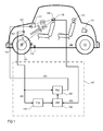
- a simple single-channel feedforward active RNC system may be constructed as shown in Figure 1 .
- Vibrations that originate from a wheel 101 moving on a road surface are detected by a suspension acceleration sensor 102 which is mechanically coupled with a suspension device 103 of an automotive vehicle 104 and which outputs a noise and vibration signal x(n) that represents the detected vibrations and, thus, correlates with the road noise audible within the cabin.
- an error signal e(n) representing noise present in the cabin of the vehicle 104 is detected by a microphone 105 arranged within the cabin in a headrest 106 of a seat (e.g., the driver's seat) .
- the road noise originating from the wheel 101 is mechanically transferred to the microphone 105 according to a transfer characteristic P(z).
- a signal y(n) having a waveform inverse in phase to that of the road noise audible within the cabin is generated by an adaptive filter formed by controllable filter 108 and filter controller 109, based on the thus identified transfer characteristic W(z) and the noise and vibration signal x(n). From signal y(n) a waveform inverse in phase to that of the road noise audible within the cabin is then generated by the loudspeaker 111, which may be arranged in the cabin, to thereby reduce the road noise within the cabin.
- the exemplary system described above employs a straightforward single-channel feedforward filtered-x LMS control structure 107 for the sake of simplicity, but other control structures, e.g., multi-channel structures with a multiplicity of additional channels, a multiplicity of additional noise sensors 112, a multiplicity of additional microphones 113, and a multiplicity of additional loudspeakers 114, may be applied as well.
- control structures e.g., multi-channel structures with a multiplicity of additional channels, a multiplicity of additional noise sensors 112, a multiplicity of additional microphones 113, and a multiplicity of additional loudspeakers 114, may be applied as well.
- FIG. 2 shows an active road noise control system 200 which is a multi-channel type active road noise control system capable of suppressing noise from a plurality of noise and vibration sources.
- the active road noise control system 200 comprises a multiplicity n of noise and vibration sensors 201, a multiplicity l of loudspeakers 202, a multiplicity m of microphones 203, and an adaptive control circuit 204 which operates to minimize the error between noise from the noise and vibration sources (primary noise) and cancelling noise (secondary noise).
- the adaptive control circuit 204 may include a number of control circuits provided for each of the loudspeakers 202, which create cancelling signals for cancelling noise from corresponding noise and vibration sources.
- the frequency range of noise to be reduced is limited to a low frequency range. That is, the conventional systems are not intended to reduce noise over its entire frequency range. Further, adaptive digital filters used in these systems have such characteristics as to be able to reduce only low frequency noise components, although processing noise over a wide frequency range is desired. In the active RNC systems disclosed herein, careful arrangement of the sensors allows for more sensitivity and a broader operating frequency range.
- RNC systems as described above may exhibit a limited noise reduction capability when the acceleration sensors' dynamic ranges, i.e., the ratios between maximum amplitudes of signals output by the sensors and noise that originates from the sensors and that is contained in the signals output by the sensors (i.e., signal-to-noise ratio), are not sufficient, as is the case with conventional acceleration sensors used for suspension set-up and vibration control.
- signal-to-noise ratio the ratios between maximum amplitudes of signals output by the sensors and noise that originates from the sensors and that is contained in the signals output by the sensors
- it is rather costly to provide sensors with better dynamic ranges.
- simple ways are described that allow for using acceleration sensors with minor dynamic ranges in active road noise systems.
- a multiplicity of (i.e., at least two) acceleration sensors which is in the present example four (identical) acceleration sensors 301 - 304, are connected to a summer module 305 which sums up sense signals 306 - 309 provided by the acceleration sensors 301 - 304 and outputs a sum signal 310 representative of the sum of sense signals 306 - 309.
- the acceleration sensors 301 - 304 may be unidirectional sensors, i.e., sensors that have their maximum sensitivity only in one single direction such as a direction x of a given coordinate system x-y-z (referred to herein as pointing in this direction).
- multi-directional sensors have their maximum sensitivities in at least two directions but not in all directions.
- a two-directional sensor has two sensitivity maxima in two different (perpendicular) directions.
- Omni-directional sensors have approximately constant sensitivities independent of the direction.
- the acceleration sensors 301 - 304 may form a sensor arrangement in which all sensors are unidirectional and point in the same direction x or may, alternatively, point in different directions.
- Figure 4 shows a three-directional acceleration sensor 401 with three sensitivity maxima in three different (perpendicular) directions x, y and z.
- the acceleration sensor 401 generates three sense signals 402 - 404 which are summed up by a summing module 405 to provide a sum signal 406.
- a summing module 405 instead of the three-directional acceleration sensor 401 three unidirectional sensors, each pointing in one of the three directions x, y and z, may be used.
- an array with a multiplicity of (e.g., four) acceleration sensors 501-504, which are arranged in a specific pattern, e.g., evenly distributed over a virtual or real sphere's surface and pointing radial (r) outward from the sphere, may be employed as shown in Figure 5 .
- a summing module 505 receives sense signals 506 - 509 from the acceleration sensors 501-504, sums them up and provides a sum signal 510 representative of the sum of the sense signals 506 - 509.
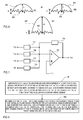
- Figure 6 illustrates two exemplary sense signals 601 and 602, each of which have a harmonic component 603, 604 such as a (pure) sinus signal, and a noise component 605, 606.
- the harmonic components 603 and 604 may have a power A and the noise may have a power N.
- a sum signal 607 is obtained in which the harmonic components 603 and 604 add to a harmonic component 608 of sum signal 607 and noise components 605 and 606 are combined to provide a noise component 609 of sum signal 607.
- the power of the noise component 609 is almost the same as either noise component 605 or noise component 609 since the summation of random signals such as noise does not increase the power of the summed noise significantly due to the random amplitudes of the noise components.
- harmonic signals such as sinus signals
- the power of the sum of two identical sinus signals is twice the power that one signal has, so that when summing up mixed signals with harmonic and random components the dynamic range increases.
- I in dynamic range or signal-to-noise ratio
- N is the number of sensors combined.
- the summing modules 305, 405 and 505 may include, in case of digital signal processing, simple digital hardware adders or signal processors that perform respective adding operations, or may include, in case of analog signal processing, analog summing circuits such as the example circuit shown in Figure 7 .
- an operational amplifier 701 has an inverse input, a non-inverse input and an output.
- An ohmic resistor 702 is connected between output and inverse input of operational amplifier 701 to provide a feedback path.
- Sense signals 703 - 706 from four acceleration sensors (not shown) are supplied via ohmic resistors 707 - 710 to the inverse input of operational amplifier 701.
- the non-inverse input of operational amplifier 701 is connect to ground 711 and the output of operational amplifier 701 forms an output 712 of the analog summing module.
- an exemplary noise and vibration sensing method may include (801) generating with an acceleration sensor arrangement at least two sense signals representative of the acceleration that acts on the acceleration sensor arrangement, wherein the sense signals have dynamic ranges which are the ratios between maximum amplitudes of the sense signals and noise created by the acceleration sensor arrangement, and (802) summing up the at least two sense signals to provide a sum signal, wherein the sum signal includes noise created by the acceleration sensor arrangement and wherein the sum signal has a dynamic range which is the ratio between a maximum amplitude of the sum signal and the noise included in the sum signal, the dynamic range of the sum signal being greater than the arithmetic mean of the dynamic ranges of the sense signals.
- acceleration sensors are used as noise and vibration sensors, delivering the desired reference signals. If those signals exhibit a considerable noise floor, which is noise generated by the sensors themselves in contrast to noise and vibrations to be measured, and thus exhibit a small dynamic range, the whole RNC system is doomed to fail.
- acceleration sensors and acceleration sensor arrangements often output a multiplicity of sense signals. If sensor signals stem from multi-axis sensors or sensor arrangements mounted at almost the same local area and/or having the same orientation (x, y or z axis), these signals may be combined as described above to increase the system's dynamic. Thus, an underperforming RNC system may be enhanced by combining appropriate sense signals of a multiplicity of under-performing sensors.
- multiple cheap low-performing acceleration sensors may be used instead of a single expensive high-performing acceleration sensor to reduce overall costs, balancing out sensor costs and differences in their performance.
Landscapes
- Physics & Mathematics (AREA)
- Engineering & Computer Science (AREA)
- Acoustics & Sound (AREA)
- Multimedia (AREA)
- General Physics & Mathematics (AREA)
- Soundproofing, Sound Blocking, And Sound Damping (AREA)
- Measurement Of Mechanical Vibrations Or Ultrasonic Waves (AREA)
- Fittings On The Vehicle Exterior For Carrying Loads, And Devices For Holding Or Mounting Articles (AREA)
Priority Applications (4)
| Application Number | Priority Date | Filing Date | Title |
|---|---|---|---|
| EP15185236.5A EP3144928B1 (fr) | 2015-09-15 | 2015-09-15 | Système de suppression du bruit de la route actif |
| JP2016158707A JP6882867B2 (ja) | 2015-09-15 | 2016-08-12 | 騒音振動検知 |
| CN201610796624.8A CN106525220B (zh) | 2015-09-15 | 2016-08-31 | 噪声和振动感测 |
| US15/266,731 US10096314B2 (en) | 2015-09-15 | 2016-09-15 | Noise and vibration sensing |
Applications Claiming Priority (1)
| Application Number | Priority Date | Filing Date | Title |
|---|---|---|---|
| EP15185236.5A EP3144928B1 (fr) | 2015-09-15 | 2015-09-15 | Système de suppression du bruit de la route actif |
Publications (2)
| Publication Number | Publication Date |
|---|---|
| EP3144928A1 true EP3144928A1 (fr) | 2017-03-22 |
| EP3144928B1 EP3144928B1 (fr) | 2021-03-24 |
Family
ID=54148359
Family Applications (1)
| Application Number | Title | Priority Date | Filing Date |
|---|---|---|---|
| EP15185236.5A Active EP3144928B1 (fr) | 2015-09-15 | 2015-09-15 | Système de suppression du bruit de la route actif |
Country Status (4)
| Country | Link |
|---|---|
| US (1) | US10096314B2 (fr) |
| EP (1) | EP3144928B1 (fr) |
| JP (1) | JP6882867B2 (fr) |
| CN (1) | CN106525220B (fr) |
Families Citing this family (13)
| Publication number | Priority date | Publication date | Assignee | Title |
|---|---|---|---|---|
| US10520356B2 (en) * | 2018-01-05 | 2019-12-31 | Center For Integrated Smart Sensors Foundation | Apparatus, method and monitoring system for measuring noise between floors |
| JP6992518B2 (ja) * | 2018-01-09 | 2022-02-04 | トヨタ紡織株式会社 | タイヤ騒音低減装置 |
| US10235987B1 (en) * | 2018-02-23 | 2019-03-19 | GM Global Technology Operations LLC | Method and apparatus that cancel component noise using feedforward information |
| US10347236B1 (en) * | 2018-02-28 | 2019-07-09 | Harman International Industries, Incorporated | Method and apparatus for continuously optimized road noise cancellation |
| US10741165B2 (en) | 2018-08-31 | 2020-08-11 | Bose Corporation | Systems and methods for noise-cancellation with shaping and weighting filters |
| US10629183B2 (en) | 2018-08-31 | 2020-04-21 | Bose Corporation | Systems and methods for noise-cancellation using microphone projection |
| US10706834B2 (en) | 2018-08-31 | 2020-07-07 | Bose Corporation | Systems and methods for disabling adaptation in an adaptive feedforward control system |
| US10410620B1 (en) | 2018-08-31 | 2019-09-10 | Bose Corporation | Systems and methods for reducing acoustic artifacts in an adaptive feedforward control system |
| US10593317B1 (en) * | 2018-12-20 | 2020-03-17 | Harman International Industries, Incorporated | Reducing audibility of sensor noise floor in a road noise cancellation system |
| CN110010118B (zh) * | 2019-04-16 | 2021-03-09 | 中国船舶科学研究中心(中国船舶重工集团公司第七0二研究所) | 一种集成于道路照明系统的噪声主动控制系统 |
| CN110211384B (zh) * | 2019-06-24 | 2020-07-24 | 中国汽车工程研究院股份有限公司 | 基于车车通讯的路况实现方法 |
| US12217733B2 (en) * | 2022-02-04 | 2025-02-04 | Harman International Industries, Incorporated | Road noise cancellation shaping filters |
| CN115116424B (zh) * | 2022-06-28 | 2025-11-14 | 青岛歌尔智能传感器有限公司 | 道路噪声消除方法、装置、设备及可读存储介质 |
Citations (5)
| Publication number | Priority date | Publication date | Assignee | Title |
|---|---|---|---|---|
| EP0721178A2 (fr) * | 1995-01-05 | 1996-07-10 | DIGISONIX, Inc. | Système de communication multi-canaux |
| EP0762146A1 (fr) * | 1995-09-12 | 1997-03-12 | PRAKLA-SEISMOS GmbH | Capteur sismique |
| GB2455410A (en) * | 2007-12-05 | 2009-06-10 | Pgs Geophysical As | Attenuating noise in marine seismic streamers by combining sensor outputs to form wavenumber filters and also using bandpass filters |
| EP2293116A2 (fr) * | 2009-08-27 | 2011-03-09 | PGS Geophysical AS | Regroupement de capteur pour flûte sismique marine à double capteur et procédé d'étude sismique |
| DE3644858A1 (de) * | 1986-08-07 | 2013-12-05 | The Secretary Of State For Defence In Her Britannic Majesty's Government Of The United Kingdom Of Great Britain And Northern Ireland | Überwachungssystem für abgestrahlte Schiffsgeräusche |
Family Cites Families (22)
| Publication number | Priority date | Publication date | Assignee | Title |
|---|---|---|---|---|
| GB8429309D0 (en) * | 1984-11-20 | 1984-12-27 | Secr Defence | Measurement of wave propagation power flow |
| US4953089A (en) * | 1988-05-09 | 1990-08-28 | Lord Corporation | Hybrid analog digital control method and apparatus for estimation of absolute velocity in active suspension systems |
| DE4101985A1 (de) * | 1991-01-24 | 1992-07-30 | Domarkas Andrew | Verfahren zum ermitteln von unregelmaessigkeiten zweier miteinander arbeitender elemente |
| US5386372A (en) * | 1992-03-12 | 1995-01-31 | Honda Giken Kogyo Kabushiki Kaisha | Vibration/noise control system for vehicles |
| JP3101745B2 (ja) * | 1992-03-18 | 2000-10-23 | 株式会社日立製作所 | 振動インテンシティ解析装置 |
| JPH06110473A (ja) * | 1992-09-29 | 1994-04-22 | Mazda Motor Corp | 車両用振動低減装置 |
| JPH06110474A (ja) * | 1992-09-30 | 1994-04-22 | Matsushita Electric Ind Co Ltd | 消音装置 |
| US6324290B1 (en) * | 1994-03-08 | 2001-11-27 | Bridgestone Corporation | Method and apparatus for diagnosing sound source and sound vibration source |
| KR0170657B1 (ko) * | 1994-08-31 | 1999-03-30 | 김광호 | 색신호에 있는 윤곽을 보정하는 방법 및 이를 칼라 비디오기기에서 구현하기 위한 회로 |
| JP4066786B2 (ja) * | 2001-12-28 | 2008-03-26 | 株式会社村田製作所 | 力学量センサ |
| KR100630156B1 (ko) * | 2005-09-16 | 2006-10-02 | 삼성전자주식회사 | 개인 항법 기기에서 걸음 검출 장치 및 방법 |
| JP4735319B2 (ja) * | 2006-02-17 | 2011-07-27 | 日産自動車株式会社 | 能動振動騒音制御装置 |
| JP4857897B2 (ja) * | 2006-05-12 | 2012-01-18 | 日産自動車株式会社 | 騒音制御方法および騒音制御装置 |
| JP4951296B2 (ja) * | 2006-09-05 | 2012-06-13 | 株式会社鶴見精機 | 漏水判定装置、漏水判定方法 |
| JP2009031032A (ja) * | 2007-07-25 | 2009-02-12 | Ocean Engineering Corp | 複数の加速度センサーにより地震計を構成するための処理方法および構成方法 |
| JP2011121534A (ja) * | 2009-12-14 | 2011-06-23 | Honda Motor Co Ltd | 能動型騒音制御装置 |
| JP5557565B2 (ja) * | 2010-03-19 | 2014-07-23 | 本田技研工業株式会社 | 能動型振動騒音制御装置 |
| JP5757742B2 (ja) * | 2010-03-25 | 2015-07-29 | セイコーインスツル株式会社 | 電子機器、歩数計、およびプログラム |
| JP5634893B2 (ja) * | 2011-01-21 | 2014-12-03 | 本田技研工業株式会社 | 能動型振動騒音制御装置 |
| US9121790B2 (en) * | 2011-01-28 | 2015-09-01 | GM Global Technology Operations LLC | Methods and systems for evaluating tire properties |
| US9459238B1 (en) * | 2011-03-14 | 2016-10-04 | Raytheon Company | Methods and apparatus for using acoustic inspection of containers to image objects |
| CN103513196B (zh) * | 2012-06-19 | 2015-12-02 | 上海联影医疗科技有限公司 | 磁共振系统、磁共振接收机及其接收信号处理方法和装置 |
-
2015
- 2015-09-15 EP EP15185236.5A patent/EP3144928B1/fr active Active
-
2016
- 2016-08-12 JP JP2016158707A patent/JP6882867B2/ja active Active
- 2016-08-31 CN CN201610796624.8A patent/CN106525220B/zh active Active
- 2016-09-15 US US15/266,731 patent/US10096314B2/en active Active
Patent Citations (5)
| Publication number | Priority date | Publication date | Assignee | Title |
|---|---|---|---|---|
| DE3644858A1 (de) * | 1986-08-07 | 2013-12-05 | The Secretary Of State For Defence In Her Britannic Majesty's Government Of The United Kingdom Of Great Britain And Northern Ireland | Überwachungssystem für abgestrahlte Schiffsgeräusche |
| EP0721178A2 (fr) * | 1995-01-05 | 1996-07-10 | DIGISONIX, Inc. | Système de communication multi-canaux |
| EP0762146A1 (fr) * | 1995-09-12 | 1997-03-12 | PRAKLA-SEISMOS GmbH | Capteur sismique |
| GB2455410A (en) * | 2007-12-05 | 2009-06-10 | Pgs Geophysical As | Attenuating noise in marine seismic streamers by combining sensor outputs to form wavenumber filters and also using bandpass filters |
| EP2293116A2 (fr) * | 2009-08-27 | 2011-03-09 | PGS Geophysical AS | Regroupement de capteur pour flûte sismique marine à double capteur et procédé d'étude sismique |
Also Published As
| Publication number | Publication date |
|---|---|
| JP6882867B2 (ja) | 2021-06-02 |
| CN106525220A (zh) | 2017-03-22 |
| US10096314B2 (en) | 2018-10-09 |
| JP2017058369A (ja) | 2017-03-23 |
| CN106525220B (zh) | 2021-03-09 |
| EP3144928B1 (fr) | 2021-03-24 |
| US20170076712A1 (en) | 2017-03-16 |
Similar Documents
| Publication | Publication Date | Title |
|---|---|---|
| US10096314B2 (en) | Noise and vibration sensing | |
| US10134380B2 (en) | Noise and vibration sensing | |
| KR102720622B1 (ko) | 로드 및 엔진 노이즈 컨트롤 | |
| EP3353773B1 (fr) | Détection de bruit et de vibrations | |
| EP3159891B1 (fr) | Détection de bruit et de vibrations | |
| EP2251860B1 (fr) | Système et méthode de contrôle actif de bruit avec sélection adaptative de haut-parleur | |
| US10810991B2 (en) | Active road noise control | |
| EP3157001B1 (fr) | Contrôle de bruit de rotation du moteur et de bruit de route |
Legal Events
| Date | Code | Title | Description |
|---|---|---|---|
| PUAI | Public reference made under article 153(3) epc to a published international application that has entered the european phase |
Free format text: ORIGINAL CODE: 0009012 |
|
| STAA | Information on the status of an ep patent application or granted ep patent |
Free format text: STATUS: THE APPLICATION HAS BEEN PUBLISHED |
|
| AK | Designated contracting states |
Kind code of ref document: A1 Designated state(s): AL AT BE BG CH CY CZ DE DK EE ES FI FR GB GR HR HU IE IS IT LI LT LU LV MC MK MT NL NO PL PT RO RS SE SI SK SM TR |
|
| AX | Request for extension of the european patent |
Extension state: BA ME |
|
| STAA | Information on the status of an ep patent application or granted ep patent |
Free format text: STATUS: REQUEST FOR EXAMINATION WAS MADE |
|
| 17P | Request for examination filed |
Effective date: 20170914 |
|
| RBV | Designated contracting states (corrected) |
Designated state(s): AL AT BE BG CH CY CZ DE DK EE ES FI FR GB GR HR HU IE IS IT LI LT LU LV MC MK MT NL NO PL PT RO RS SE SI SK SM TR |
|
| STAA | Information on the status of an ep patent application or granted ep patent |
Free format text: STATUS: EXAMINATION IS IN PROGRESS |
|
| 17Q | First examination report despatched |
Effective date: 20190508 |
|
| GRAP | Despatch of communication of intention to grant a patent |
Free format text: ORIGINAL CODE: EPIDOSNIGR1 |
|
| STAA | Information on the status of an ep patent application or granted ep patent |
Free format text: STATUS: GRANT OF PATENT IS INTENDED |
|
| INTG | Intention to grant announced |
Effective date: 20201021 |
|
| GRAS | Grant fee paid |
Free format text: ORIGINAL CODE: EPIDOSNIGR3 |
|
| GRAA | (expected) grant |
Free format text: ORIGINAL CODE: 0009210 |
|
| STAA | Information on the status of an ep patent application or granted ep patent |
Free format text: STATUS: THE PATENT HAS BEEN GRANTED |
|
| AK | Designated contracting states |
Kind code of ref document: B1 Designated state(s): AL AT BE BG CH CY CZ DE DK EE ES FI FR GB GR HR HU IE IS IT LI LT LU LV MC MK MT NL NO PL PT RO RS SE SI SK SM TR |
|
| REG | Reference to a national code |
Ref country code: GB Ref legal event code: FG4D |
|
| REG | Reference to a national code |
Ref country code: CH Ref legal event code: EP |
|
| REG | Reference to a national code |
Ref country code: IE Ref legal event code: FG4D |
|
| REG | Reference to a national code |
Ref country code: AT Ref legal event code: REF Ref document number: 1375296 Country of ref document: AT Kind code of ref document: T Effective date: 20210415 Ref country code: DE Ref legal event code: R096 Ref document number: 602015067159 Country of ref document: DE |
|
| REG | Reference to a national code |
Ref country code: LT Ref legal event code: MG9D |
|
| PG25 | Lapsed in a contracting state [announced via postgrant information from national office to epo] |
Ref country code: HR Free format text: LAPSE BECAUSE OF FAILURE TO SUBMIT A TRANSLATION OF THE DESCRIPTION OR TO PAY THE FEE WITHIN THE PRESCRIBED TIME-LIMIT Effective date: 20210324 Ref country code: GR Free format text: LAPSE BECAUSE OF FAILURE TO SUBMIT A TRANSLATION OF THE DESCRIPTION OR TO PAY THE FEE WITHIN THE PRESCRIBED TIME-LIMIT Effective date: 20210625 Ref country code: FI Free format text: LAPSE BECAUSE OF FAILURE TO SUBMIT A TRANSLATION OF THE DESCRIPTION OR TO PAY THE FEE WITHIN THE PRESCRIBED TIME-LIMIT Effective date: 20210324 Ref country code: NO Free format text: LAPSE BECAUSE OF FAILURE TO SUBMIT A TRANSLATION OF THE DESCRIPTION OR TO PAY THE FEE WITHIN THE PRESCRIBED TIME-LIMIT Effective date: 20210624 Ref country code: BG Free format text: LAPSE BECAUSE OF FAILURE TO SUBMIT A TRANSLATION OF THE DESCRIPTION OR TO PAY THE FEE WITHIN THE PRESCRIBED TIME-LIMIT Effective date: 20210624 |
|
| PG25 | Lapsed in a contracting state [announced via postgrant information from national office to epo] |
Ref country code: SE Free format text: LAPSE BECAUSE OF FAILURE TO SUBMIT A TRANSLATION OF THE DESCRIPTION OR TO PAY THE FEE WITHIN THE PRESCRIBED TIME-LIMIT Effective date: 20210324 Ref country code: RS Free format text: LAPSE BECAUSE OF FAILURE TO SUBMIT A TRANSLATION OF THE DESCRIPTION OR TO PAY THE FEE WITHIN THE PRESCRIBED TIME-LIMIT Effective date: 20210324 Ref country code: LV Free format text: LAPSE BECAUSE OF FAILURE TO SUBMIT A TRANSLATION OF THE DESCRIPTION OR TO PAY THE FEE WITHIN THE PRESCRIBED TIME-LIMIT Effective date: 20210324 |
|
| REG | Reference to a national code |
Ref country code: NL Ref legal event code: MP Effective date: 20210324 |
|
| REG | Reference to a national code |
Ref country code: AT Ref legal event code: MK05 Ref document number: 1375296 Country of ref document: AT Kind code of ref document: T Effective date: 20210324 |
|
| PG25 | Lapsed in a contracting state [announced via postgrant information from national office to epo] |
Ref country code: NL Free format text: LAPSE BECAUSE OF FAILURE TO SUBMIT A TRANSLATION OF THE DESCRIPTION OR TO PAY THE FEE WITHIN THE PRESCRIBED TIME-LIMIT Effective date: 20210324 |
|
| PG25 | Lapsed in a contracting state [announced via postgrant information from national office to epo] |
Ref country code: EE Free format text: LAPSE BECAUSE OF FAILURE TO SUBMIT A TRANSLATION OF THE DESCRIPTION OR TO PAY THE FEE WITHIN THE PRESCRIBED TIME-LIMIT Effective date: 20210324 Ref country code: CZ Free format text: LAPSE BECAUSE OF FAILURE TO SUBMIT A TRANSLATION OF THE DESCRIPTION OR TO PAY THE FEE WITHIN THE PRESCRIBED TIME-LIMIT Effective date: 20210324 Ref country code: LT Free format text: LAPSE BECAUSE OF FAILURE TO SUBMIT A TRANSLATION OF THE DESCRIPTION OR TO PAY THE FEE WITHIN THE PRESCRIBED TIME-LIMIT Effective date: 20210324 Ref country code: AT Free format text: LAPSE BECAUSE OF FAILURE TO SUBMIT A TRANSLATION OF THE DESCRIPTION OR TO PAY THE FEE WITHIN THE PRESCRIBED TIME-LIMIT Effective date: 20210324 Ref country code: SM Free format text: LAPSE BECAUSE OF FAILURE TO SUBMIT A TRANSLATION OF THE DESCRIPTION OR TO PAY THE FEE WITHIN THE PRESCRIBED TIME-LIMIT Effective date: 20210324 |
|
| PG25 | Lapsed in a contracting state [announced via postgrant information from national office to epo] |
Ref country code: PL Free format text: LAPSE BECAUSE OF FAILURE TO SUBMIT A TRANSLATION OF THE DESCRIPTION OR TO PAY THE FEE WITHIN THE PRESCRIBED TIME-LIMIT Effective date: 20210324 Ref country code: PT Free format text: LAPSE BECAUSE OF FAILURE TO SUBMIT A TRANSLATION OF THE DESCRIPTION OR TO PAY THE FEE WITHIN THE PRESCRIBED TIME-LIMIT Effective date: 20210726 Ref country code: ES Free format text: LAPSE BECAUSE OF FAILURE TO SUBMIT A TRANSLATION OF THE DESCRIPTION OR TO PAY THE FEE WITHIN THE PRESCRIBED TIME-LIMIT Effective date: 20210324 Ref country code: SK Free format text: LAPSE BECAUSE OF FAILURE TO SUBMIT A TRANSLATION OF THE DESCRIPTION OR TO PAY THE FEE WITHIN THE PRESCRIBED TIME-LIMIT Effective date: 20210324 Ref country code: RO Free format text: LAPSE BECAUSE OF FAILURE TO SUBMIT A TRANSLATION OF THE DESCRIPTION OR TO PAY THE FEE WITHIN THE PRESCRIBED TIME-LIMIT Effective date: 20210324 Ref country code: IS Free format text: LAPSE BECAUSE OF FAILURE TO SUBMIT A TRANSLATION OF THE DESCRIPTION OR TO PAY THE FEE WITHIN THE PRESCRIBED TIME-LIMIT Effective date: 20210724 |
|
| REG | Reference to a national code |
Ref country code: DE Ref legal event code: R097 Ref document number: 602015067159 Country of ref document: DE |
|
| PG25 | Lapsed in a contracting state [announced via postgrant information from national office to epo] |
Ref country code: DK Free format text: LAPSE BECAUSE OF FAILURE TO SUBMIT A TRANSLATION OF THE DESCRIPTION OR TO PAY THE FEE WITHIN THE PRESCRIBED TIME-LIMIT Effective date: 20210324 Ref country code: AL Free format text: LAPSE BECAUSE OF FAILURE TO SUBMIT A TRANSLATION OF THE DESCRIPTION OR TO PAY THE FEE WITHIN THE PRESCRIBED TIME-LIMIT Effective date: 20210324 |
|
| PLBE | No opposition filed within time limit |
Free format text: ORIGINAL CODE: 0009261 |
|
| STAA | Information on the status of an ep patent application or granted ep patent |
Free format text: STATUS: NO OPPOSITION FILED WITHIN TIME LIMIT |
|
| PG25 | Lapsed in a contracting state [announced via postgrant information from national office to epo] |
Ref country code: SI Free format text: LAPSE BECAUSE OF FAILURE TO SUBMIT A TRANSLATION OF THE DESCRIPTION OR TO PAY THE FEE WITHIN THE PRESCRIBED TIME-LIMIT Effective date: 20210324 |
|
| 26N | No opposition filed |
Effective date: 20220104 |
|
| REG | Reference to a national code |
Ref country code: CH Ref legal event code: PL |
|
| REG | Reference to a national code |
Ref country code: BE Ref legal event code: MM Effective date: 20210930 |
|
| GBPC | Gb: european patent ceased through non-payment of renewal fee |
Effective date: 20210915 |
|
| PG25 | Lapsed in a contracting state [announced via postgrant information from national office to epo] |
Ref country code: IS Free format text: LAPSE BECAUSE OF FAILURE TO SUBMIT A TRANSLATION OF THE DESCRIPTION OR TO PAY THE FEE WITHIN THE PRESCRIBED TIME-LIMIT Effective date: 20210724 Ref country code: MC Free format text: LAPSE BECAUSE OF FAILURE TO SUBMIT A TRANSLATION OF THE DESCRIPTION OR TO PAY THE FEE WITHIN THE PRESCRIBED TIME-LIMIT Effective date: 20210324 |
|
| PG25 | Lapsed in a contracting state [announced via postgrant information from national office to epo] |
Ref country code: LU Free format text: LAPSE BECAUSE OF NON-PAYMENT OF DUE FEES Effective date: 20210915 Ref country code: IE Free format text: LAPSE BECAUSE OF NON-PAYMENT OF DUE FEES Effective date: 20210915 Ref country code: GB Free format text: LAPSE BECAUSE OF NON-PAYMENT OF DUE FEES Effective date: 20210915 Ref country code: FR Free format text: LAPSE BECAUSE OF NON-PAYMENT OF DUE FEES Effective date: 20210930 Ref country code: BE Free format text: LAPSE BECAUSE OF NON-PAYMENT OF DUE FEES Effective date: 20210930 |
|
| PG25 | Lapsed in a contracting state [announced via postgrant information from national office to epo] |
Ref country code: LI Free format text: LAPSE BECAUSE OF NON-PAYMENT OF DUE FEES Effective date: 20210930 Ref country code: CH Free format text: LAPSE BECAUSE OF NON-PAYMENT OF DUE FEES Effective date: 20210930 |
|
| PG25 | Lapsed in a contracting state [announced via postgrant information from national office to epo] |
Ref country code: IT Free format text: LAPSE BECAUSE OF FAILURE TO SUBMIT A TRANSLATION OF THE DESCRIPTION OR TO PAY THE FEE WITHIN THE PRESCRIBED TIME-LIMIT Effective date: 20210324 |
|
| PG25 | Lapsed in a contracting state [announced via postgrant information from national office to epo] |
Ref country code: HU Free format text: LAPSE BECAUSE OF FAILURE TO SUBMIT A TRANSLATION OF THE DESCRIPTION OR TO PAY THE FEE WITHIN THE PRESCRIBED TIME-LIMIT; INVALID AB INITIO Effective date: 20150915 |
|
| PG25 | Lapsed in a contracting state [announced via postgrant information from national office to epo] |
Ref country code: CY Free format text: LAPSE BECAUSE OF FAILURE TO SUBMIT A TRANSLATION OF THE DESCRIPTION OR TO PAY THE FEE WITHIN THE PRESCRIBED TIME-LIMIT Effective date: 20210324 |
|
| P01 | Opt-out of the competence of the unified patent court (upc) registered |
Effective date: 20230526 |
|
| PG25 | Lapsed in a contracting state [announced via postgrant information from national office to epo] |
Ref country code: MK Free format text: LAPSE BECAUSE OF FAILURE TO SUBMIT A TRANSLATION OF THE DESCRIPTION OR TO PAY THE FEE WITHIN THE PRESCRIBED TIME-LIMIT Effective date: 20210324 |
|
| PG25 | Lapsed in a contracting state [announced via postgrant information from national office to epo] |
Ref country code: TR Free format text: LAPSE BECAUSE OF FAILURE TO SUBMIT A TRANSLATION OF THE DESCRIPTION OR TO PAY THE FEE WITHIN THE PRESCRIBED TIME-LIMIT Effective date: 20210324 |
|
| PG25 | Lapsed in a contracting state [announced via postgrant information from national office to epo] |
Ref country code: MT Free format text: LAPSE BECAUSE OF FAILURE TO SUBMIT A TRANSLATION OF THE DESCRIPTION OR TO PAY THE FEE WITHIN THE PRESCRIBED TIME-LIMIT Effective date: 20210324 |
|
| PGFP | Annual fee paid to national office [announced via postgrant information from national office to epo] |
Ref country code: DE Payment date: 20250820 Year of fee payment: 11 |