EP3144947A1 - Ensemble interrupteur, procédé de commande d'ensemble interrupteur, dispositif de commande et station de base - Google Patents
Ensemble interrupteur, procédé de commande d'ensemble interrupteur, dispositif de commande et station de base Download PDFInfo
- Publication number
- EP3144947A1 EP3144947A1 EP15803723.4A EP15803723A EP3144947A1 EP 3144947 A1 EP3144947 A1 EP 3144947A1 EP 15803723 A EP15803723 A EP 15803723A EP 3144947 A1 EP3144947 A1 EP 3144947A1
- Authority
- EP
- European Patent Office
- Prior art keywords
- phase shifter
- control instruction
- controller
- normally open
- driving rod
- Prior art date
- Legal status (The legal status is an assumption and is not a legal conclusion. Google has not performed a legal analysis and makes no representation as to the accuracy of the status listed.)
- Granted
Links
Images

Classifications
-
- H—ELECTRICITY
- H01—ELECTRIC ELEMENTS
- H01Q—ANTENNAS, i.e. RADIO AERIALS
- H01Q3/00—Arrangements for changing or varying the orientation or the shape of the directional pattern of the waves radiated from an antenna or antenna system
- H01Q3/26—Arrangements for changing or varying the orientation or the shape of the directional pattern of the waves radiated from an antenna or antenna system varying the relative phase or relative amplitude of energisation between two or more active radiating elements; varying the distribution of energy across a radiating aperture
- H01Q3/30—Arrangements for changing or varying the orientation or the shape of the directional pattern of the waves radiated from an antenna or antenna system varying the relative phase or relative amplitude of energisation between two or more active radiating elements; varying the distribution of energy across a radiating aperture varying the relative phase between the radiating elements of an array
- H01Q3/34—Arrangements for changing or varying the orientation or the shape of the directional pattern of the waves radiated from an antenna or antenna system varying the relative phase or relative amplitude of energisation between two or more active radiating elements; varying the distribution of energy across a radiating aperture varying the relative phase between the radiating elements of an array by electrical means
- H01Q3/36—Arrangements for changing or varying the orientation or the shape of the directional pattern of the waves radiated from an antenna or antenna system varying the relative phase or relative amplitude of energisation between two or more active radiating elements; varying the distribution of energy across a radiating aperture varying the relative phase between the radiating elements of an array by electrical means with variable phase-shifters
-
- H—ELECTRICITY
- H01—ELECTRIC ELEMENTS
- H01P—WAVEGUIDES; RESONATORS, LINES, OR OTHER DEVICES OF THE WAVEGUIDE TYPE
- H01P1/00—Auxiliary devices
- H01P1/10—Auxiliary devices for switching or interrupting
- H01P1/12—Auxiliary devices for switching or interrupting by mechanical chopper
-
- H—ELECTRICITY
- H01—ELECTRIC ELEMENTS
- H01Q—ANTENNAS, i.e. RADIO AERIALS
- H01Q1/00—Details of, or arrangements associated with, antennas
- H01Q1/12—Supports; Mounting means
- H01Q1/22—Supports; Mounting means by structural association with other equipment or articles
- H01Q1/24—Supports; Mounting means by structural association with other equipment or articles with receiving set
- H01Q1/241—Supports; Mounting means by structural association with other equipment or articles with receiving set used in mobile communications, e.g. GSM
- H01Q1/246—Supports; Mounting means by structural association with other equipment or articles with receiving set used in mobile communications, e.g. GSM specially adapted for base stations
-
- H—ELECTRICITY
- H01—ELECTRIC ELEMENTS
- H01Q—ANTENNAS, i.e. RADIO AERIALS
- H01Q21/00—Antenna arrays or systems
- H01Q21/06—Arrays of individually energised antenna units similarly polarised and spaced apart
-
- H—ELECTRICITY
- H01—ELECTRIC ELEMENTS
- H01Q—ANTENNAS, i.e. RADIO AERIALS
- H01Q21/00—Antenna arrays or systems
- H01Q21/06—Arrays of individually energised antenna units similarly polarised and spaced apart
- H01Q21/22—Antenna units of the array energised non-uniformly in amplitude or phase, e.g. tapered array or binomial array
-
- Y—GENERAL TAGGING OF NEW TECHNOLOGICAL DEVELOPMENTS; GENERAL TAGGING OF CROSS-SECTIONAL TECHNOLOGIES SPANNING OVER SEVERAL SECTIONS OF THE IPC; TECHNICAL SUBJECTS COVERED BY FORMER USPC CROSS-REFERENCE ART COLLECTIONS [XRACs] AND DIGESTS
- Y02—TECHNOLOGIES OR APPLICATIONS FOR MITIGATION OR ADAPTATION AGAINST CLIMATE CHANGE
- Y02P—CLIMATE CHANGE MITIGATION TECHNOLOGIES IN THE PRODUCTION OR PROCESSING OF GOODS
- Y02P90/00—Enabling technologies with a potential contribution to greenhouse gas [GHG] emissions mitigation
- Y02P90/02—Total factory control, e.g. smart factories, flexible manufacturing systems [FMS] or integrated manufacturing systems [IMS]
Definitions
- the present invention relates to the wireless communications field, and in particular, to a switch assembly, a switch assembly control method, a controller, and a base station.
- a scenario in which gating is performed on a signal or a power supply is usually involved.
- a corresponding gating switch usually needs to be arranged.
- an integrated semiconductor chip switch or a relay switch is usually used as a gating switch in a base station.
- An internal test on an antenna array is used as an example.
- a test signal generated by a signal source needs to be sent to the antenna array to be tested.
- an integrated semiconductor chip switch or a relay switch may be arranged as a gating switch between the signal source and the antenna array.
- a controller controls the gating switch to open or close.
- embodiments of the present invention provide a switch assembly, a switch assembly control method, a controller, and a base station.
- the technical solutions are as follows:
- control command is a calibration command
- controller is configured to send the calibration command to the phase shifter according to the Antenna Interface Standards Group AISG protocol.
- the phase shifter is configured to: when the control instruction is a first control instruction, drive, according to the first control instruction, the driving rod to move to the maximum stroke.
- the phase shifter is configured to: when the control instruction is a second control instruction, drive, according to the second control instruction, the driving rod to move to the minimum stroke.
- an antenna array corresponding to the base station there is an antenna array corresponding to the base station, the antenna array is connected to one end of a feeder line, and N ports included at the other end of the feeder line are respectively connected to N remote electrical tilt units in the base station, where N ⁇ 2; one end of the mechanical normally open switch is connected, by using a coupler, to a port at which the antenna array is connected to the feeder line, and the other end of the mechanical normally open switch is connected to a signal source; when the mechanical normally open switch closes, a signal generated by the signal source is sent to the feeder line by using the port at which the antenna array is connected to the feeder line; and the controller is configured to: after sending the control instruction to the phase shifter, obtain background noise detection information at the ports at which the feeder line is connected to the N remote electrical tilt units, and determine, according to the background noise detection information, a remote electrical tilt unit corresponding to the antenna array.
- a switch assembly control method which is used in the switch assembly according to the first aspect, where the method includes:
- the sending, by the controller, a control instruction to the phase shifter includes:
- the sending, by the controller, a control instruction to the phase shifter includes:
- the sending, by the controller, a control instruction to the phase shifter includes:
- an antenna array corresponding to the base station, the antenna array is connected to one end of a feeder line, and N ports included at the other end of the feeder line are respectively connected to N remote electrical tilt units in the base station, where N ⁇ 2; one end of the mechanical normally open switch is connected, by using a coupler, to a port at which the antenna array is connected to the feeder line, and the other end of the mechanical normally open switch is connected to a signal source; when the mechanical normally open switch closes, a signal generated by the signal source is sent to the feeder line by using the port at which the antenna array is connected to the feeder line; and the method further includes:
- a controller which is used in the switch assembly according to the first aspect, where the controller includes:
- control instruction sending module is configured to send the calibration command to the phase shifter according to the Antenna Interface Standards Group AISG protocol, where the control instruction is the calibration command.
- control instruction sending module is configured to send a first control instruction to the phase shifter, and the first control instruction is used to instruct the phase shifter to drive the driving rod to move to a maximum stroke, where when the driving rod is at the maximum stroke, the movable contact is in the specified position.
- control instruction sending module is configured to send a second control instruction to the phase shifter, and the second control instruction is used to instruct the phase shifter to drive the driving rod to move to a minimum stroke, where when the driving rod is at the minimum stroke, the movable contact is in the specified position.
- an antenna array corresponding to the base station the antenna array is connected to one end of a feeder line, and N ports included at the other end of the feeder line are respectively connected to N remote electrical tilt units in the base station, where N ⁇ 2; one end of the mechanical normally open switch is connected, by using a coupler, to a port at which the antenna array is connected to the feeder line, and the other end of the mechanical normally open switch is connected to a signal source; when the mechanical normally open switch closes, a signal generated by the signal source is sent to the feeder line by using the port at which the antenna array is connected to the feeder line; and the controller further includes:
- a base station where the base station includes:
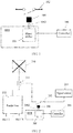
- FIG. 1 shows a structural diagram of a switch assembly according to an embodiment of the present invention.
- the switch assembly may be used in a base station that includes a RET (Remote Electrical Tilt unit, remote electrical tilt unit).
- the switch assembly includes: a mechanical normally open switch 102, a movable contact 104, and a controller 106.
- the controller 106 is connected to a phase shifter 108 of the remote electrical tilt unit, and the movable contact 104 is arranged to move with a driving rod 1082 of the phase shifter 108; when the movable contact 104 reaches a specified position, the mechanical normally open switch 102 is triggered to close.
- the controller 106 is configured to receive an operation instruction, where the operation instruction is used to instruct the controller 106 to control the mechanical normally open switch 102 to close.
- the controller 106 is configured to send a control instruction to the phase shifter 108.
- the phase shifter 108 is configured to receive the control instruction, and drive the driving rod 1082 according to the control command, so that the movable contact 104 moves to the specified position.
- a remote electrical tilt antenna is an antenna that electronically adjusts a downtilt angle.
- a principle of the remote electrical tilt antenna is to change a phase of an antenna element of a collinear array, amplitude values of vertical and horizontal components, and a value of field strength of a synthesized component, so as to adjust a downtilt angle of a vertical directivity diagram of the antenna, and adjust a coverage range of the antenna.
- the downtilt angle of the remote electrical tilt antenna that is externally connected to the base station may be adjusted by using the remote electrical tilt unit RET that is arranged inside the base station.
- a mechanical normally open switch corresponding to a driving rod of a phase shifter in a RET is arranged, the driving rod of the phase shifter is controlled to drive a movable contact of the mechanical normally open switch, and an existing driving structure in the RET is used to control the mechanical normally open switch to close.
- the mechanical normally open switch is a mechanical part, where spacing between ports is relatively large, interference to a base station signal is not easily caused, intermodulation distortion is not caused, and reliability of the mechanical part is higher than that of a nonlinear element.
- no dedicated driving structure needs to be arranged for the movable contact of the mechanical normally open switch, so that a size of the switch assembly is reduced, and an installation difficulty is reduced.
- an arranged phase shifter of a remote electrical tilt unit in a base station is used as a driving mechanism of a mechanical normally open switch, and a movable contact of the mechanical normally open switch is arranged to move with a driving rod of the phase shifter; a controller sends a control instruction to the phase shifter after receiving an operation instruction that is used to instruct the controller to control the mechanical normally open switch to close, and the phase shifter drives the driving rod according to the control command, so that the movable contact moves to a specified position, and the mechanical normally open switch is triggered to close.
- the mechanical normally open switch is a mechanical part and no dedicated driving structure needs to be arranged for the movable contact of the mechanical normally open switch, a size of the switch assembly is reduced, and a prior-art problem that interference is caused to a base station signal because an integrated semiconductor chip radio frequency switch is a nonlinear element and a problem that installation is relatively difficult because a volume of a relay switch is relatively large are resolved, thereby reducing an installation difficulty while avoiding interference caused to a base station signal.
- FIG. 2 shows a structural diagram of a switch assembly according to another embodiment of the present invention.
- the switch assembly may be used in a base station that includes a RET. That the switch assembly is used to connect or disconnect a connection between a signal source and an antenna array of a remote electrical tilt antenna when an internal test is performed on the remote electrical tilt antenna externally connected to the base station is used as an example.
- the switch assembly includes: a mechanical normally open switch 202, a movable contact 204, and a controller 206.
- the controller 206 is connected to a phase shifter 208 of the remote electrical tilt unit, and the movable contact 204 is arranged to move with a driving rod 2082 of the phase shifter 208; when the movable contact 204 reaches a specified position, the mechanical normally open switch 202 is triggered to close.
- the controller 206 is configured to receive an operation instruction, where the operation instruction is used to instruct the controller 206 to control the mechanical normally open switch 202 to close.
- the controller 206 is configured to send a control instruction to the phase shifter 208.
- the phase shifter 208 is configured to receive the control instruction, and drive the driving rod 2082 according to the control command, so that the movable contact 204 moves to the specified position.
- a remote electrical tilt antenna is an antenna that electronically adjusts a downtilt angle.
- a principle of the remote electrical tilt antenna is to change a phase of an antenna element of a collinear array, amplitude values of vertical and horizontal components, and a value of field strength of a synthesized component, so as to adjust a downtilt angle of a vertical directivity diagram of the antenna, and adjust a coverage range of the antenna.
- the downtilt angle of the remote electrical tilt antenna that is externally connected to the base station may be adjusted by using the remote electrical tilt unit RET that is arranged inside the base station.
- the elastic metal blade is arranged on a moving path of the movable contact, and when the movable contact moves, the elastic metal blade may be touched.
- the elastic metal blade may connect both ends of the switch; when the movable contact leaves the specified position, the elastic metal blade is restored to an original status, so that the switch is opened.
- a mechanical normally open switch corresponding to a driving rod of a phase shifter in a RET is arranged, the driving rod of the phase shifter is controlled to drive a movable contact of the mechanical normally open switch, and an existing driving structure in the RET is used to control the mechanical normally open switch to close.
- the mechanical normally open switch is a mechanical part, where spacing between ports is relatively large, interference to a base station signal is not easily caused, intermodulation distortion is not caused, and reliability of the mechanical part is higher than that of a nonlinear element.
- no dedicated driving structure needs to be arranged for the movable contact of the mechanical normally open switch, so that a size of the switch assembly is reduced, and an installation difficulty is reduced.
- the control command is a calibration command
- the controller 206 is configured to send the calibration command to the phase shifter 208 according to the AISG (Antenna Interface Standards Group, Antenna Interface Standards Group) protocol.
- AISG Antenna Interface Standards Group, Antenna Interface Standards Group
- the controller in this embodiment of the present invention may control the phase shifter according to the protocol originally supported by the phase shifter. There is no need to develop a specialized control command, and there is only a need to set a parameter in the existing calibration command to achieve a purpose of controlling the switch to close, so that a difficulty of development and deployment is further reduced.
- the phase shifter 208 is configured to: when the control instruction is a first control instruction, drive, according to the first control instruction, the driving rod 2082 to move to a maximum stroke. When the driving rod is at the maximum stroke, the movable contact is in the specified position.
- phase shifter 208 is configured to: when the control instruction is a second control instruction, drive, according to the second control instruction, the driving rod 2082 to move to a minimum stroke. When the driving rod is at the minimum stroke, the movable contact is in the specified position.
- the phase shifter is further configured to control a downtilt angle of a vertical directivity diagram of the antenna. Therefore, a stroke of the driving rod when the phase shifter controls the mechanical normally open switch to close needs to be set to be out of a stroke range when the phase shifter controls the downtilt angle of the vertical directivity diagram of the antenna, so as to avoid a fault that is caused by closing of the mechanical normally open switch when the phase shifter controls the downtilt angle of the vertical directivity diagram of the antenna. Specifically, it may be set as follows: When the phase shifter controls the driving rod to move to the maximum stroke or the minimum stroke, the movable contact moves with the driving rod to the specified position.
- the mechanical normally open switch is opened or closed by using an elastic metal blade is used as an example.
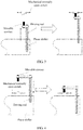
- a driving rod stroke shown in FIG. 3 when the phase shifter controls the driving rod to move to the maximum stroke, the movable contact moves with the driving rod to the specified position, and triggers the mechanical normally open switch to close.
- a schematic diagram of another driving rod stroke shown in FIG. 4 when the phase shifter controls the driving rod to move to the minimum stroke, the movable contact moves with the driving rod to the specified position, and triggers the mechanical normally open switch to close.
- the antenna array 210 is connected to one end of a feeder line 212, and N ports included at the other end of the feeder line 212 are respectively connected to N remote electrical tilt units RETs in the base station, where N ⁇ 2; one end of the mechanical normally open switch 202 is connected, by using a coupler 214, to a port at which the antenna array 210 is connected to the feeder line 212, and the other end of the mechanical normally open switch 202 is connected to a signal source 216; when the mechanical normally open switch 202 closes, a signal generated by the signal source 216 is sent to the feeder line 212 by using the port at which the antenna array 210 is connected to the feeder line 212.
- the controller 206 is configured to: after sending the control instruction to the phase shifter 208, obtain background noise detection information at the ports at which the feeder line 212 is connected to the N remote electrical tilt units, and determine, according to the background noise detection information, a remote electrical tilt unit corresponding to the antenna array 210.
- each antenna array corresponds to one RET, and correspondences between the antenna arrays and the RETs are unknown.
- Each antenna array is connected to one switch unit by using a coupler, where the switch units are connected to a same signal source, and the switch units are controlled by a same controller.
- the switch unit includes a mechanical normally open switch, a movable contact, and a phase shifter. Mechanical normally open switches corresponding to the antenna arrays are respectively arranged on phase shifter sides of different RETs, and the movable contact is arranged on the top of a driving rod. A relationship between each phase shifter and the mechanical normally open switch of each antenna array is known.
- phase shifter in the RET may control a mechanical normally open switch corresponding to the antenna array to close, but may be incapable of controlling a downtilt angle of a vertical directivity diagram of the antenna array.
- a corresponding test instruction is sent to the controller, and the controller sends, according to the test instruction, a control command to a phase shifter in a switch assembly corresponding to the antenna array.
- the controller sends a control command to a phase shifter corresponding to the antenna array 1.
- the phase shifter drives a movable contact to a specified position, so that a corresponding mechanical normally open switch closes and the antenna array 1 is connected to the signal source.
- a signal sent by the signal source enters a feeder line by using a coupler, which causes background noise (that is, background noise) at a port corresponding to the other side of the feeder line to change.
- a receiver on a base station side performs a background noise test on a signal received from each port of the feeder line.
- the controller obtains background noise test information of each port, and determines that a RET corresponding to a port at which background noise changes accordingly is the RET corresponding to the antenna array 1.
- an arranged phase shifter of a remote electrical tilt unit in a base station is used as a driving mechanism of a mechanical normally open switch, and a movable contact of the mechanical normally open switch is arranged to move with a driving rod of the phase shifter; a controller sends a control instruction to the phase shifter after receiving an operation instruction that is used to instruct the controller to control the mechanical normally open switch to close, and the phase shifter drives the driving rod according to the control command, so that the movable contact moves to a specified position, and the mechanical normally open switch is triggered to close.
- the mechanical normally open switch is a mechanical part and no dedicated driving structure needs to be arranged for the movable contact of the mechanical normally open switch, a size of the switch assembly is reduced, and a prior-art problem that interference is caused to a base station signal because an integrated semiconductor chip radio frequency switch is a nonlinear element and a problem that installation is relatively difficult because a volume of a relay switch is relatively large are resolved, thereby reducing an installation difficulty while avoiding interference caused to a base station signal.
- an ASIG calibration command is sent to the phase shifter so as to control the movable contact to move and control the normally open switch to open or close, thereby achieving an effect of further reducing a difficulty of development and deployment.
- the switch assembly when the phase shifter drives, according to the control instruction, the driving rod to move to a maximum stroke or a minimum stroke, the movable contact that moves with the driving rod triggers the switch to close, thereby avoiding occurrence of a fault that the mechanical normally open switch may be triggered to close when an antenna array normally adjusts a downtilt angle of a vertical directivity diagram.
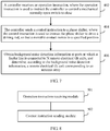
- FIG. 6 shows a method flowchart of a switch assembly control method according to an embodiment of the present invention.
- the method may be used in the switch assembly shown in FIG. 1 or FIG. 2 to control a mechanical normally open switch to close, where the switch assembly is used in a base station that includes a remote electrical tilt unit.
- the antenna test method may include:
- the switch assembly includes: the mechanical normally open switch, the movable contact, and the controller, where the controller is connected to the phase shifter of the remote electrical tilt unit, and the movable contact is arranged to move with the driving rod of the phase shifter; when the movable contact reaches the specified position, the mechanical normally open switch is triggered to close.
- a control instruction is sent to an existing phase shifter of a RET in a base station, and the phase shifter drives a driving rod, so that a movable contact that moves with the driving rod moves to a specified position to trigger a mechanical normally open switch to close.
- the mechanical normally open switch is a mechanical part and no dedicated driving structure needs to be arranged for the movable contact of the mechanical normally open switch, a size of the switch assembly is reduced, and a prior-art problem that interference is caused to a base station signal because an integrated semiconductor chip radio frequency switch is a nonlinear element and a problem that installation is relatively difficult because a volume of a relay switch is relatively large are resolved, thereby reducing an installation difficulty while avoiding interference caused to a base station signal.
- FIG. 7 shows a method flowchart of a switch assembly control method according to another embodiment of the present invention.
- the method may be used in the switch assembly shown in FIG. 1 or FIG. 2 to control a mechanical normally open switch to close, where the switch assembly is used in a base station that includes a remote electrical tilt unit. That the switch assembly is used to connect or disconnect a connection between a signal source and an antenna array of a remote electrical tilt antenna when an internal test is performed on the remote electrical tilt antenna externally connected to the base station is used as an example.
- the antenna test method may include:
- the switch assembly includes: the mechanical normally open switch, a movable contact, and the controller, where the controller is connected to a phase shifter of the remote electrical tilt unit, and the movable contact is arranged to move with a driving rod of the phase shifter; when the movable contact reaches a specified position, the mechanical normally open switch is triggered to close.
- Step 404 The controller sends a control instruction to a phase shifter, where the control instruction is used to instruct the phase shifter to drive the driving rod, so that the movable contact moves to a specified position.
- the control instruction is the calibration command, where the controller sends the calibration command to the phase shifter according to the Antenna Interface Standards Group AISG protocol.
- the controller in this embodiment of the present invention may control the phase shifter according to the protocol originally supported by the phase shifter. There is no need to develop a specialized control command, and there is only a need to set a parameter in the existing calibration command to achieve a purpose of controlling the switch to close, so that a difficulty of development and deployment is further reduced.
- the controller sends a first control instruction to the phase shifter, where the first control instruction is used to instruct the phase shifter to drive the driving rod to move to a maximum stroke.
- the driving rod is at the maximum stroke, the movable contact is in the specified position.
- the controller sends a second control instruction to the phase shifter, where the second control instruction is used to instruct the phase shifter to drive the driving rod to move to a minimum stroke.
- the second control instruction is used to instruct the phase shifter to drive the driving rod to move to a minimum stroke.
- the phase shifter is further configured to control a downtilt angle of a vertical directivity diagram of the antenna. Therefore, a stroke of the driving rod when the phase shifter controls the mechanical normally open switch to close needs to be set to be out of a stroke range when the phase shifter controls the downtilt angle of the vertical directivity diagram of the antenna, so as to avoid a fault that is caused by closing of the mechanical normally open switch when the phase shifter controls the downtilt angle of the vertical directivity diagram of the antenna. Specifically, it may be set as follows: When the phase shifter controls the driving rod to move to the maximum stroke or the minimum stroke, the movable contact moves with the driving rod to the specified position.
- the mechanical normally open switch is opened or closed by using an elastic metal blade is used as an example.
- a driving rod stroke shown in FIG. 3 when the phase shifter controls the driving rod to move to the maximum stroke, the movable contact moves with the driving rod to the specified position, and triggers the mechanical normally open switch to close.
- a schematic diagram of another driving rod stroke shown in FIG. 4 when the phase shifter controls the driving rod to move to the minimum stroke, the movable contact moves with the driving rod to the specified position, and triggers the mechanical normally open switch to close.
- Step 406 Obtain background noise detection information at ports at which the feeder line is connected to the N remote electrical tilt units, and determine, according to the background noise detection information, a remote electrical tilt unit corresponding to the antenna array.
- the antenna array is connected to one end of a feeder line, and N ports included at the other end of the feeder line are respectively connected to N remote electrical tilt units in the base station, where N ⁇ 2; one end of the mechanical normally open switch is connected, by using a coupler, to a port at which the antenna array is connected to the feeder line, and the other end of the mechanical normally open switch is connected to a signal source; when the mechanical normally open switch closes, a signal generated by the signal source is sent to the feeder line by using the port at which the antenna array is connected to the feeder line.
- each antenna array corresponds to one RET, and correspondences between the antenna arrays and the RETs are unknown.
- Each antenna array is connected to one switch unit by using a coupler, where the switch units are connected to a same signal source, and the switch units are controlled by a same controller.
- the switch unit includes a mechanical normally open switch, a movable contact, and a phase shifter. Mechanical normally open switches corresponding to the antenna arrays are respectively arranged on phase shifter sides of different RETs, and the movable contact is arranged on the top of a driving rod. A relationship between each phase shifter and the mechanical normally open switch of each antenna array is known.
- phase shifter in the RET may control a mechanical normally open switch corresponding to the antenna array to close, but may be incapable of controlling a downtilt angle of a vertical directivity diagram of the antenna array.
- a corresponding test instruction is sent to the controll, and the controller sends, according to the test instruction, a control command to a phase shifter in a switch assembly corresponding to the antenna array.
- the controller sends a control command to a phase shifter corresponding to the antenna array 1.
- the phase shifter drives a movable contact to a specified position, so that a corresponding mechanical normally open switch closes and the antenna array 1 is connected to the signal source.
- a signal sent by the signal source enters a feeder line by using a coupler, which causes background noise (that is, background noise) at a port corresponding to the other side of the feeder line to change.
- a receiver on a base station side performs a background noise test on a signal received from each port of the feeder line.
- the controller obtains background noise test information of each port, and determines that a RET corresponding to a port at which background noise changes accordingly is a RET that controls a downtilt angle of a vertical directivity diagram of the antenna array 1.
- a control instruction is sent to an existing phase shifter of a RET in a base station, and the phase shifter drives a driving rod, so that a movable contact that moves with the driving rod moves to a specified position to trigger a mechanical normally open switch to close.
- the mechanical normally open switch is a mechanical part and no dedicated driving structure needs to be arranged for the movable contact of the mechanical normally open switch, a size of the switch assembly is reduced, and a prior-art problem that interference is caused to a base station signal because an integrated semiconductor chip radio frequency switch is a nonlinear element and a problem that installation is relatively difficult because a volume of a relay switch is relatively large are resolved, thereby reducing an installation difficulty while avoiding interference caused to a base station signal.
- a controller sends an ASIG calibration command to the phase shifter so as to control the movable contact to move and control the normally open switch to open or close, thereby achieving an effect of further reducing a difficulty of development and deployment.
- a control instruction used to instruct the phase shifter to drive the driving rod to move to a maximum stroke or a minimum stroke is sent, so that the movable contact that moves with the driving rod triggers the switch to close, thereby avoiding occurrence of a fault that the mechanical normally open switch may be triggered to close when an antenna array normally adjusts a downtilt angle of a vertical directivity diagram.
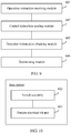
- FIG. 8 shows an apparatus structural diagram of a controller according to an embodiment of the present invention.
- the controller may be used in the switch assembly shown in FIG. 1 or FIG. 2 to control a mechanical normally open switch to close, where the switch assembly is used in a base station that includes a remote electrical tilt unit.
- the controller may include:
- a control instruction is sent to an existing phase shifter of a RET in a base station, and the phase shifter drives a driving rod, so that a movable contact that moves with the driving rod moves to a specified position to trigger a mechanical normally open switch to close.
- the mechanical normally open switch is a mechanical part and no dedicated driving structure needs to be arranged for the movable contact of the mechanical normally open switch, a size of the switch assembly is reduced, and a prior-art problem that interference is caused to a base station signal because an integrated semiconductor chip radio frequency switch is a nonlinear element and a problem that installation is relatively difficult because a volume of a relay switch is relatively large are resolved, thereby reducing an installation difficulty while avoiding interference caused to a base station signal.
- FIG. 9 shows an apparatus structural diagram of a controller according to another embodiment of the present invention.
- the controller may be used in the switch assembly shown in FIG. 1 or FIG. 2 to control a mechanical normally open switch to close, where the switch assembly is used in a base station that includes a remote electrical tilt unit. That the switch assembly is used to connect or disconnect a connection between a signal source and an antenna array of a remote electrical tilt antenna when an internal test is performed on the remote electrical tilt antenna externally connected to the base station is used as an example.
- the controller may include:
- the control instruction sending module 602 is configured to send the calibration command to the phase shifter according to the Antenna Interface Standards Group AISG protocol, where the control instruction is the calibration command.
- the control instruction sending module 602 is configured to send a first control instruction to the phase shifter, where the first control instruction is used to instruct the phase shifter to drive the driving rod to move to a maximum stroke.
- the control instruction sending module 602 is configured to send a second control instruction to the phase shifter, where the second control instruction is used to instruct the phase shifter to drive the driving rod to move to a minimum stroke.
- the antenna array is connected to one end of a feeder line, and N ports included at the other end of the feeder line are respectively connected to N remote electrical tilt units in the base station, where N ⁇ 2;
- one end of the mechanical normally open switch is connected, by using a coupler, to a port at which the antenna array is connected to the feeder line, and the other end of the mechanical normally open switch is connected to a signal source; when the mechanical normally open switch closes, a signal generated by the signal source is sent to the feeder line by using the port at which the antenna array is connected to the feeder line; and the controller further includes:
- a control instruction is sent to an existing phase shifter of a RET in a base station, and the phase shifter drives a driving rod, so that a movable contact that moves with the driving rod moves to a specified position to trigger a mechanical normally open switch to close.
- the mechanical normally open switch is a mechanical part and no dedicated driving structure needs to be arranged for the movable contact of the mechanical normally open switch, a size of the switch assembly is reduced, and a prior-art problem that interference is caused to a base station signal because an integrated semiconductor chip radio frequency switch is a nonlinear element and a problem that installation is relatively difficult because a volume of a relay switch is relatively large are resolved, thereby reducing an installation difficulty while avoiding interference caused to a base station signal.
- an ASIG calibration command is sent to the phase shifter so as to control the movable contact to move and control the normally open switch to open or close, thereby achieving an effect of further reducing a difficulty of development and deployment.
- a control instruction used to instruct the phase shifter to drive the driving rod to move to a maximum stroke or a minimum stroke is sent, so that the movable contact that moves with the driving rod triggers the switch to close, thereby avoiding occurrence of a fault that the mechanical normally open switch may be triggered to close when an antenna array normally adjusts a downtilt angle of a vertical directivity diagram.
- FIG. 10 shows a composition block diagram of a base station according to an embodiment of the present invention.
- the base station includes:
- a controller sends a control instruction to an existing phase shifter of a RET in a base station, and the phase shifter drives a driving rod, so that a movable contact that moves with the driving rod moves to a specified position to trigger a mechanical normally open switch to close.
- the mechanical normally open switch is a mechanical part and no dedicated driving structure needs to be arranged for the movable contact of the mechanical normally open switch, a size of the switch assembly is reduced, and a prior-art problem that interference is caused to a base station signal because an integrated semiconductor chip radio frequency switch is a nonlinear element and a problem that installation is relatively difficult because a volume of a relay switch is relatively large are resolved, thereby reducing an installation difficulty while avoiding interference caused to a base station signal.
- the controller sends an ASIG calibration command to the phase shifter so as to control the movable contact to move and control the normally open switch to open or close, thereby achieving an effect of further reducing a difficulty of development and deployment.
- the controller sends a control instruction used to instruct the phase shifter to drive the driving rod to move to a maximum stroke or a minimum stroke, so that the movable contact that moves with the driving rod triggers the switch to close, thereby avoiding occurrence of a fault that the mechanical normally open switch may be triggered to close when an antenna array normally adjusts a downtilt angle of a vertical directivity diagram.
- the program may be stored in a computer-readable storage medium.
- the storage medium may include: a read-only memory, a magnetic disk, or an optical disc.
Landscapes
- Engineering & Computer Science (AREA)
- Computer Networks & Wireless Communication (AREA)
- Variable-Direction Aerials And Aerial Arrays (AREA)
Applications Claiming Priority (2)
| Application Number | Priority Date | Filing Date | Title |
|---|---|---|---|
| CN201410249347.XA CN104090531B (zh) | 2014-06-06 | 2014-06-06 | 开关组件、开关组件控制方法、控制器及基站 |
| PCT/CN2015/080723 WO2015184995A1 (fr) | 2014-06-06 | 2015-06-03 | Ensemble interrupteur, procédé de commande d'ensemble interrupteur, dispositif de commande et station de base |
Publications (3)
| Publication Number | Publication Date |
|---|---|
| EP3144947A1 true EP3144947A1 (fr) | 2017-03-22 |
| EP3144947A4 EP3144947A4 (fr) | 2017-07-26 |
| EP3144947B1 EP3144947B1 (fr) | 2018-09-19 |
Family
ID=51638253
Family Applications (1)
| Application Number | Title | Priority Date | Filing Date |
|---|---|---|---|
| EP15803723.4A Active EP3144947B1 (fr) | 2014-06-06 | 2015-06-03 | Ensemble interrupteur, procédé de commande d'ensemble interrupteur, dispositif de commande et station de base |
Country Status (5)
| Country | Link |
|---|---|
| US (1) | US10396458B2 (fr) |
| EP (1) | EP3144947B1 (fr) |
| JP (1) | JP6393786B2 (fr) |
| CN (1) | CN104090531B (fr) |
| WO (1) | WO2015184995A1 (fr) |
Families Citing this family (10)
| Publication number | Priority date | Publication date | Assignee | Title |
|---|---|---|---|---|
| CN104090531B (zh) | 2014-06-06 | 2017-01-04 | 西安华为技术有限公司 | 开关组件、开关组件控制方法、控制器及基站 |
| CN105897297B (zh) * | 2016-05-19 | 2019-03-12 | 北京佰才邦技术有限公司 | 调节天线的装置及方法 |
| CN109314308A (zh) | 2016-06-15 | 2019-02-05 | 康普技术有限责任公司 | 用于控制远程电子下倾基站天线的多个移相器的致动器 |
| US10854967B2 (en) | 2017-03-30 | 2020-12-01 | Commscope Technologies Llc | Base station antennas that are configurable for either independent or common down tilt control and related methods |
| CN110462927B (zh) * | 2017-03-31 | 2021-09-14 | 华为技术有限公司 | 天线下倾角调节装置及通信设备 |
| CN109193121B (zh) * | 2018-08-27 | 2020-11-06 | 京信通信技术(广州)有限公司 | 可调波束宽度的天线 |
| CN111180892B (zh) * | 2018-11-09 | 2021-05-07 | 京信通信技术(广州)有限公司 | 天线及移相器 |
| US10916843B1 (en) * | 2019-10-29 | 2021-02-09 | Terrance O'Brien Woodbridge | Method and system to reduce the impact of electromagnetic pulses on cellular tower sites |
| US11304069B2 (en) * | 2019-11-27 | 2022-04-12 | Commscope Technologies Llc | Base station antennas having field-enabled remote electronic tilt capabilities |
| CN114123153B (zh) * | 2020-08-31 | 2024-05-24 | 中国移动通信集团重庆有限公司 | 基站的有源天线单元一体化远程空开及基站 |
Family Cites Families (18)
| Publication number | Priority date | Publication date | Assignee | Title |
|---|---|---|---|---|
| US4331853A (en) * | 1977-12-14 | 1982-05-25 | Ireland Robert W | Multiple switch actuating mechanism |
| SE0003369D0 (sv) | 2000-09-18 | 2000-09-18 | Abb Ab | Elkopplare |
| JP4088140B2 (ja) * | 2002-11-21 | 2008-05-21 | Dxアンテナ株式会社 | アンテナシステム |
| JP3913696B2 (ja) | 2003-03-19 | 2007-05-09 | 三洋電機株式会社 | 基地局装置 |
| US7529215B2 (en) * | 2003-11-17 | 2009-05-05 | Telefonaktiebolaget Lm Ericsson (Publ) | Encapsulation of independent transmissions over internal interface of distributed radio base station |
| US7242291B2 (en) * | 2005-06-08 | 2007-07-10 | Sensata Technologies, Inc. | Arc fault circuit interrupter test circuit and test board |
| EP2232633A4 (fr) * | 2007-11-26 | 2014-03-12 | Powerwave Technologies Inc | Antenne à inclinaison de faisceau et azimut variables à entraînement unique pour réseau sans fil |
| MX2010008827A (es) * | 2008-02-11 | 2010-12-20 | Amphenol Corp | Antena de inclinacion electrica remota con ensamble de motor y embrague. |
| JP4872106B2 (ja) * | 2008-06-26 | 2012-02-08 | Necシステムテクノロジー株式会社 | プッシュスイッチを有する機器の制御装置および制御方法 |
| JP2010096433A (ja) * | 2008-10-16 | 2010-04-30 | Hitachi Plant Technologies Ltd | 遠隔操作装置および遠隔操作システム |
| US8027703B2 (en) | 2009-02-11 | 2011-09-27 | Amphenol Corporation | Multi-beam antenna with multi-device control unit |
| JP2011205609A (ja) * | 2010-03-04 | 2011-10-13 | Autonetworks Technologies Ltd | 送信装置およびアンテナ制御装置 |
| CN102055069B (zh) | 2010-11-01 | 2014-10-29 | 京信通信系统(中国)有限公司 | 电调天线控制系统及方法 |
| US20120196545A1 (en) * | 2011-01-28 | 2012-08-02 | Georg Schmidt | Antenna array and method for synthesizing antenna patterns |
| CN102386030B (zh) * | 2011-10-28 | 2015-07-15 | 温州凯信电气有限公司 | 一种智能型液压电磁式断路器 |
| CN202395751U (zh) * | 2011-11-01 | 2012-08-22 | 南京鑫轩电子系统工程有限公司 | 铁氧体移相器数字化控制电路 |
| US9502764B2 (en) * | 2014-06-05 | 2016-11-22 | T-Mobile Usa, Inc. | Autonomous antenna tilt compensation |
| CN104090531B (zh) * | 2014-06-06 | 2017-01-04 | 西安华为技术有限公司 | 开关组件、开关组件控制方法、控制器及基站 |
-
2014
- 2014-06-06 CN CN201410249347.XA patent/CN104090531B/zh active Active
-
2015
- 2015-06-03 WO PCT/CN2015/080723 patent/WO2015184995A1/fr not_active Ceased
- 2015-06-03 JP JP2016571342A patent/JP6393786B2/ja active Active
- 2015-06-03 EP EP15803723.4A patent/EP3144947B1/fr active Active
-
2016
- 2016-12-06 US US15/370,910 patent/US10396458B2/en active Active
Also Published As
| Publication number | Publication date |
|---|---|
| US20170084996A1 (en) | 2017-03-23 |
| EP3144947A4 (fr) | 2017-07-26 |
| WO2015184995A1 (fr) | 2015-12-10 |
| EP3144947B1 (fr) | 2018-09-19 |
| CN104090531A (zh) | 2014-10-08 |
| CN104090531B (zh) | 2017-01-04 |
| JP6393786B2 (ja) | 2018-09-19 |
| JP2017520182A (ja) | 2017-07-20 |
| US10396458B2 (en) | 2019-08-27 |
Similar Documents
| Publication | Publication Date | Title |
|---|---|---|
| EP3144947B1 (fr) | Ensemble interrupteur, procédé de commande d'ensemble interrupteur, dispositif de commande et station de base | |
| US12149324B2 (en) | System and method for passive reflection of RF signals | |
| US10200881B2 (en) | Reconfigurable single and multi-sector cell site system | |
| US10050341B2 (en) | Apparatus for controlling antenna of mobile-communication base station | |
| US9905911B2 (en) | Antenna for electronic device | |
| US9713198B2 (en) | Mobile communication method | |
| US20190319343A1 (en) | Antenna and network device | |
| CN112398517A (zh) | 天线切换系统及方法、存储介质 | |
| US10530035B2 (en) | Method and system for the automated alignment of antennas | |
| EP3021419A1 (fr) | Dispositif réflecteur et procédé de fonctionnement d'un dispositif réflecteur | |
| EP2937936A2 (fr) | Commande de distribution d'antenne | |
| ES2756825T3 (es) | Método y dispositivo de coincidencia | |
| US9667277B2 (en) | Apparatus for tuning voltage standing wave ratio of base station system in wireless communication network | |
| US9913129B2 (en) | Antenna control system and its operating method | |
| JP6471177B2 (ja) | 遠隔電気チルトアンテナ、基地局、およびrcuとrfポートとを整合させる方法 | |
| KR20160079421A (ko) | 안테나 장치 | |
| CN113273093B (zh) | 通信系统中天线选择的方法、设备和计算机程序产品 | |
| US10734728B2 (en) | Antenna, antenna control method, antenna control apparatus, and antenna system | |
| EP2966726A1 (fr) | Antenne équipée d'éléments rayonnants agencés horizontalement | |
| KR20140095239A (ko) | 이동 통신 시스템에서 안테나 제어 장치 및 방법 | |
| KR20110058174A (ko) | 이동통신용 차단형 안테나 어셈블리 | |
| JP2003008499A (ja) | 無線系試験システムとその方法 | |
| JP2006295543A (ja) | 移動通信システム | |
| JP2007274625A (ja) | 固定無線アクセスシステム |
Legal Events
| Date | Code | Title | Description |
|---|---|---|---|
| STAA | Information on the status of an ep patent application or granted ep patent |
Free format text: STATUS: THE INTERNATIONAL PUBLICATION HAS BEEN MADE |
|
| PUAI | Public reference made under article 153(3) epc to a published international application that has entered the european phase |
Free format text: ORIGINAL CODE: 0009012 |
|
| STAA | Information on the status of an ep patent application or granted ep patent |
Free format text: STATUS: REQUEST FOR EXAMINATION WAS MADE |
|
| 17P | Request for examination filed |
Effective date: 20161213 |
|
| AK | Designated contracting states |
Kind code of ref document: A1 Designated state(s): AL AT BE BG CH CY CZ DE DK EE ES FI FR GB GR HR HU IE IS IT LI LT LU LV MC MK MT NL NO PL PT RO RS SE SI SK SM TR |
|
| AX | Request for extension of the european patent |
Extension state: BA ME |
|
| A4 | Supplementary search report drawn up and despatched |
Effective date: 20170623 |
|
| RIC1 | Information provided on ipc code assigned before grant |
Ipc: H01Q 3/36 20060101ALI20170619BHEP Ipc: H01H 3/00 20060101AFI20170619BHEP |
|
| DAV | Request for validation of the european patent (deleted) | ||
| DAX | Request for extension of the european patent (deleted) | ||
| GRAP | Despatch of communication of intention to grant a patent |
Free format text: ORIGINAL CODE: EPIDOSNIGR1 |
|
| STAA | Information on the status of an ep patent application or granted ep patent |
Free format text: STATUS: GRANT OF PATENT IS INTENDED |
|
| RIC1 | Information provided on ipc code assigned before grant |
Ipc: H01Q 3/36 20060101ALI20180226BHEP Ipc: H01H 3/00 20060101AFI20180226BHEP |
|
| INTG | Intention to grant announced |
Effective date: 20180404 |
|
| RIN1 | Information on inventor provided before grant (corrected) |
Inventor name: SHEN, JIAN Inventor name: DUAN, FANGQING |
|
| GRAS | Grant fee paid |
Free format text: ORIGINAL CODE: EPIDOSNIGR3 |
|
| GRAA | (expected) grant |
Free format text: ORIGINAL CODE: 0009210 |
|
| STAA | Information on the status of an ep patent application or granted ep patent |
Free format text: STATUS: THE PATENT HAS BEEN GRANTED |
|
| AK | Designated contracting states |
Kind code of ref document: B1 Designated state(s): AL AT BE BG CH CY CZ DE DK EE ES FI FR GB GR HR HU IE IS IT LI LT LU LV MC MK MT NL NO PL PT RO RS SE SI SK SM TR |
|
| REG | Reference to a national code |
Ref country code: GB Ref legal event code: FG4D |
|
| REG | Reference to a national code |
Ref country code: CH Ref legal event code: EP |
|
| REG | Reference to a national code |
Ref country code: AT Ref legal event code: REF Ref document number: 1044189 Country of ref document: AT Kind code of ref document: T Effective date: 20181015 |
|
| REG | Reference to a national code |
Ref country code: IE Ref legal event code: FG4D |
|
| REG | Reference to a national code |
Ref country code: DE Ref legal event code: R096 Ref document number: 602015016745 Country of ref document: DE |
|
| REG | Reference to a national code |
Ref country code: NL Ref legal event code: MP Effective date: 20180919 |
|
| PG25 | Lapsed in a contracting state [announced via postgrant information from national office to epo] |
Ref country code: NO Free format text: LAPSE BECAUSE OF FAILURE TO SUBMIT A TRANSLATION OF THE DESCRIPTION OR TO PAY THE FEE WITHIN THE PRESCRIBED TIME-LIMIT Effective date: 20181219 Ref country code: LT Free format text: LAPSE BECAUSE OF FAILURE TO SUBMIT A TRANSLATION OF THE DESCRIPTION OR TO PAY THE FEE WITHIN THE PRESCRIBED TIME-LIMIT Effective date: 20180919 Ref country code: RS Free format text: LAPSE BECAUSE OF FAILURE TO SUBMIT A TRANSLATION OF THE DESCRIPTION OR TO PAY THE FEE WITHIN THE PRESCRIBED TIME-LIMIT Effective date: 20180919 Ref country code: GR Free format text: LAPSE BECAUSE OF FAILURE TO SUBMIT A TRANSLATION OF THE DESCRIPTION OR TO PAY THE FEE WITHIN THE PRESCRIBED TIME-LIMIT Effective date: 20181220 Ref country code: FI Free format text: LAPSE BECAUSE OF FAILURE TO SUBMIT A TRANSLATION OF THE DESCRIPTION OR TO PAY THE FEE WITHIN THE PRESCRIBED TIME-LIMIT Effective date: 20180919 Ref country code: BG Free format text: LAPSE BECAUSE OF FAILURE TO SUBMIT A TRANSLATION OF THE DESCRIPTION OR TO PAY THE FEE WITHIN THE PRESCRIBED TIME-LIMIT Effective date: 20181219 Ref country code: SE Free format text: LAPSE BECAUSE OF FAILURE TO SUBMIT A TRANSLATION OF THE DESCRIPTION OR TO PAY THE FEE WITHIN THE PRESCRIBED TIME-LIMIT Effective date: 20180919 |
|
| REG | Reference to a national code |
Ref country code: LT Ref legal event code: MG4D |
|
| PG25 | Lapsed in a contracting state [announced via postgrant information from national office to epo] |
Ref country code: LV Free format text: LAPSE BECAUSE OF FAILURE TO SUBMIT A TRANSLATION OF THE DESCRIPTION OR TO PAY THE FEE WITHIN THE PRESCRIBED TIME-LIMIT Effective date: 20180919 Ref country code: AL Free format text: LAPSE BECAUSE OF FAILURE TO SUBMIT A TRANSLATION OF THE DESCRIPTION OR TO PAY THE FEE WITHIN THE PRESCRIBED TIME-LIMIT Effective date: 20180919 Ref country code: HR Free format text: LAPSE BECAUSE OF FAILURE TO SUBMIT A TRANSLATION OF THE DESCRIPTION OR TO PAY THE FEE WITHIN THE PRESCRIBED TIME-LIMIT Effective date: 20180919 |
|
| REG | Reference to a national code |
Ref country code: AT Ref legal event code: MK05 Ref document number: 1044189 Country of ref document: AT Kind code of ref document: T Effective date: 20180919 |
|
| PG25 | Lapsed in a contracting state [announced via postgrant information from national office to epo] |
Ref country code: NL Free format text: LAPSE BECAUSE OF FAILURE TO SUBMIT A TRANSLATION OF THE DESCRIPTION OR TO PAY THE FEE WITHIN THE PRESCRIBED TIME-LIMIT Effective date: 20180919 Ref country code: ES Free format text: LAPSE BECAUSE OF FAILURE TO SUBMIT A TRANSLATION OF THE DESCRIPTION OR TO PAY THE FEE WITHIN THE PRESCRIBED TIME-LIMIT Effective date: 20180919 Ref country code: IS Free format text: LAPSE BECAUSE OF FAILURE TO SUBMIT A TRANSLATION OF THE DESCRIPTION OR TO PAY THE FEE WITHIN THE PRESCRIBED TIME-LIMIT Effective date: 20190119 Ref country code: PL Free format text: LAPSE BECAUSE OF FAILURE TO SUBMIT A TRANSLATION OF THE DESCRIPTION OR TO PAY THE FEE WITHIN THE PRESCRIBED TIME-LIMIT Effective date: 20180919 Ref country code: CZ Free format text: LAPSE BECAUSE OF FAILURE TO SUBMIT A TRANSLATION OF THE DESCRIPTION OR TO PAY THE FEE WITHIN THE PRESCRIBED TIME-LIMIT Effective date: 20180919 Ref country code: RO Free format text: LAPSE BECAUSE OF FAILURE TO SUBMIT A TRANSLATION OF THE DESCRIPTION OR TO PAY THE FEE WITHIN THE PRESCRIBED TIME-LIMIT Effective date: 20180919 Ref country code: EE Free format text: LAPSE BECAUSE OF FAILURE TO SUBMIT A TRANSLATION OF THE DESCRIPTION OR TO PAY THE FEE WITHIN THE PRESCRIBED TIME-LIMIT Effective date: 20180919 Ref country code: AT Free format text: LAPSE BECAUSE OF FAILURE TO SUBMIT A TRANSLATION OF THE DESCRIPTION OR TO PAY THE FEE WITHIN THE PRESCRIBED TIME-LIMIT Effective date: 20180919 |
|
| PG25 | Lapsed in a contracting state [announced via postgrant information from national office to epo] |
Ref country code: SK Free format text: LAPSE BECAUSE OF FAILURE TO SUBMIT A TRANSLATION OF THE DESCRIPTION OR TO PAY THE FEE WITHIN THE PRESCRIBED TIME-LIMIT Effective date: 20180919 Ref country code: SM Free format text: LAPSE BECAUSE OF FAILURE TO SUBMIT A TRANSLATION OF THE DESCRIPTION OR TO PAY THE FEE WITHIN THE PRESCRIBED TIME-LIMIT Effective date: 20180919 Ref country code: PT Free format text: LAPSE BECAUSE OF FAILURE TO SUBMIT A TRANSLATION OF THE DESCRIPTION OR TO PAY THE FEE WITHIN THE PRESCRIBED TIME-LIMIT Effective date: 20190119 |
|
| REG | Reference to a national code |
Ref country code: DE Ref legal event code: R097 Ref document number: 602015016745 Country of ref document: DE |
|
| PLBE | No opposition filed within time limit |
Free format text: ORIGINAL CODE: 0009261 |
|
| STAA | Information on the status of an ep patent application or granted ep patent |
Free format text: STATUS: NO OPPOSITION FILED WITHIN TIME LIMIT |
|
| PG25 | Lapsed in a contracting state [announced via postgrant information from national office to epo] |
Ref country code: DK Free format text: LAPSE BECAUSE OF FAILURE TO SUBMIT A TRANSLATION OF THE DESCRIPTION OR TO PAY THE FEE WITHIN THE PRESCRIBED TIME-LIMIT Effective date: 20180919 |
|
| 26N | No opposition filed |
Effective date: 20190620 |
|
| PG25 | Lapsed in a contracting state [announced via postgrant information from national office to epo] |
Ref country code: SI Free format text: LAPSE BECAUSE OF FAILURE TO SUBMIT A TRANSLATION OF THE DESCRIPTION OR TO PAY THE FEE WITHIN THE PRESCRIBED TIME-LIMIT Effective date: 20180919 |
|
| PG25 | Lapsed in a contracting state [announced via postgrant information from national office to epo] |
Ref country code: MC Free format text: LAPSE BECAUSE OF FAILURE TO SUBMIT A TRANSLATION OF THE DESCRIPTION OR TO PAY THE FEE WITHIN THE PRESCRIBED TIME-LIMIT Effective date: 20180919 |
|
| REG | Reference to a national code |
Ref country code: CH Ref legal event code: PL |
|
| GBPC | Gb: european patent ceased through non-payment of renewal fee |
Effective date: 20190603 |
|
| REG | Reference to a national code |
Ref country code: BE Ref legal event code: MM Effective date: 20190630 |
|
| PG25 | Lapsed in a contracting state [announced via postgrant information from national office to epo] |
Ref country code: TR Free format text: LAPSE BECAUSE OF FAILURE TO SUBMIT A TRANSLATION OF THE DESCRIPTION OR TO PAY THE FEE WITHIN THE PRESCRIBED TIME-LIMIT Effective date: 20180919 |
|
| PG25 | Lapsed in a contracting state [announced via postgrant information from national office to epo] |
Ref country code: IE Free format text: LAPSE BECAUSE OF NON-PAYMENT OF DUE FEES Effective date: 20190603 Ref country code: GB Free format text: LAPSE BECAUSE OF NON-PAYMENT OF DUE FEES Effective date: 20190603 |
|
| PG25 | Lapsed in a contracting state [announced via postgrant information from national office to epo] |
Ref country code: BE Free format text: LAPSE BECAUSE OF NON-PAYMENT OF DUE FEES Effective date: 20190630 Ref country code: LI Free format text: LAPSE BECAUSE OF NON-PAYMENT OF DUE FEES Effective date: 20190630 Ref country code: LU Free format text: LAPSE BECAUSE OF NON-PAYMENT OF DUE FEES Effective date: 20190603 Ref country code: CH Free format text: LAPSE BECAUSE OF NON-PAYMENT OF DUE FEES Effective date: 20190630 |
|
| PG25 | Lapsed in a contracting state [announced via postgrant information from national office to epo] |
Ref country code: FR Free format text: LAPSE BECAUSE OF NON-PAYMENT OF DUE FEES Effective date: 20190630 |
|
| PG25 | Lapsed in a contracting state [announced via postgrant information from national office to epo] |
Ref country code: CY Free format text: LAPSE BECAUSE OF FAILURE TO SUBMIT A TRANSLATION OF THE DESCRIPTION OR TO PAY THE FEE WITHIN THE PRESCRIBED TIME-LIMIT Effective date: 20180919 |
|
| PG25 | Lapsed in a contracting state [announced via postgrant information from national office to epo] |
Ref country code: MT Free format text: LAPSE BECAUSE OF FAILURE TO SUBMIT A TRANSLATION OF THE DESCRIPTION OR TO PAY THE FEE WITHIN THE PRESCRIBED TIME-LIMIT Effective date: 20180919 Ref country code: HU Free format text: LAPSE BECAUSE OF FAILURE TO SUBMIT A TRANSLATION OF THE DESCRIPTION OR TO PAY THE FEE WITHIN THE PRESCRIBED TIME-LIMIT; INVALID AB INITIO Effective date: 20150603 |
|
| PG25 | Lapsed in a contracting state [announced via postgrant information from national office to epo] |
Ref country code: MK Free format text: LAPSE BECAUSE OF FAILURE TO SUBMIT A TRANSLATION OF THE DESCRIPTION OR TO PAY THE FEE WITHIN THE PRESCRIBED TIME-LIMIT Effective date: 20180919 |
|
| P01 | Opt-out of the competence of the unified patent court (upc) registered |
Effective date: 20230524 |
|
| PGFP | Annual fee paid to national office [announced via postgrant information from national office to epo] |
Ref country code: DE Payment date: 20250429 Year of fee payment: 11 |
|
| PGFP | Annual fee paid to national office [announced via postgrant information from national office to epo] |
Ref country code: IT Payment date: 20250522 Year of fee payment: 11 |