EP3144982B1 - Source de tension échelonnable - Google Patents
Source de tension échelonnable Download PDFInfo
- Publication number
- EP3144982B1 EP3144982B1 EP16001926.1A EP16001926A EP3144982B1 EP 3144982 B1 EP3144982 B1 EP 3144982B1 EP 16001926 A EP16001926 A EP 16001926A EP 3144982 B1 EP3144982 B1 EP 3144982B1
- Authority
- EP
- European Patent Office
- Prior art keywords
- stack
- semiconductor
- voltage source
- scalable
- diode
- Prior art date
- Legal status (The legal status is an assumption and is not a legal conclusion. Google has not performed a legal analysis and makes no representation as to the accuracy of the status listed.)
- Active
Links
Images


Classifications
-
- H—ELECTRICITY
- H10—SEMICONDUCTOR DEVICES; ELECTRIC SOLID-STATE DEVICES NOT OTHERWISE PROVIDED FOR
- H10F—INORGANIC SEMICONDUCTOR DEVICES SENSITIVE TO INFRARED RADIATION, LIGHT, ELECTROMAGNETIC RADIATION OF SHORTER WAVELENGTH OR CORPUSCULAR RADIATION
- H10F19/00—Integrated devices, or assemblies of multiple devices, comprising at least one photovoltaic cell covered by group H10F10/00, e.g. photovoltaic modules
- H10F19/70—Integrated devices, or assemblies of multiple devices, comprising at least one photovoltaic cell covered by group H10F10/00, e.g. photovoltaic modules comprising bypass diodes
- H10F19/75—Integrated devices, or assemblies of multiple devices, comprising at least one photovoltaic cell covered by group H10F10/00, e.g. photovoltaic modules comprising bypass diodes the bypass diodes being integrated or directly associated with the photovoltaic cells, e.g. formed in or on the same substrate
-
- H—ELECTRICITY
- H10—SEMICONDUCTOR DEVICES; ELECTRIC SOLID-STATE DEVICES NOT OTHERWISE PROVIDED FOR
- H10D—INORGANIC ELECTRIC SEMICONDUCTOR DEVICES
- H10D8/00—Diodes
- H10D8/70—Tunnel-effect diodes
-
- H—ELECTRICITY
- H10—SEMICONDUCTOR DEVICES; ELECTRIC SOLID-STATE DEVICES NOT OTHERWISE PROVIDED FOR
- H10D—INORGANIC ELECTRIC SEMICONDUCTOR DEVICES
- H10D62/00—Semiconductor bodies, or regions thereof, of devices having potential barriers
- H10D62/80—Semiconductor bodies, or regions thereof, of devices having potential barriers characterised by the materials
- H10D62/82—Heterojunctions
- H10D62/824—Heterojunctions comprising only Group III-V materials heterojunctions, e.g. GaN/AlGaN heterojunctions
-
- H—ELECTRICITY
- H10—SEMICONDUCTOR DEVICES; ELECTRIC SOLID-STATE DEVICES NOT OTHERWISE PROVIDED FOR
- H10F—INORGANIC SEMICONDUCTOR DEVICES SENSITIVE TO INFRARED RADIATION, LIGHT, ELECTROMAGNETIC RADIATION OF SHORTER WAVELENGTH OR CORPUSCULAR RADIATION
- H10F10/00—Individual photovoltaic cells, e.g. solar cells
- H10F10/10—Individual photovoltaic cells, e.g. solar cells having potential barriers
- H10F10/14—Photovoltaic cells having only PN homojunction potential barriers
- H10F10/142—Photovoltaic cells having only PN homojunction potential barriers comprising multiple PN homojunctions, e.g. tandem cells
-
- H—ELECTRICITY
- H10—SEMICONDUCTOR DEVICES; ELECTRIC SOLID-STATE DEVICES NOT OTHERWISE PROVIDED FOR
- H10F—INORGANIC SEMICONDUCTOR DEVICES SENSITIVE TO INFRARED RADIATION, LIGHT, ELECTROMAGNETIC RADIATION OF SHORTER WAVELENGTH OR CORPUSCULAR RADIATION
- H10F10/00—Individual photovoltaic cells, e.g. solar cells
- H10F10/10—Individual photovoltaic cells, e.g. solar cells having potential barriers
- H10F10/14—Photovoltaic cells having only PN homojunction potential barriers
- H10F10/144—Photovoltaic cells having only PN homojunction potential barriers comprising only Group III-V materials, e.g. GaAs,AlGaAs, or InP photovoltaic cells
-
- H—ELECTRICITY
- H10—SEMICONDUCTOR DEVICES; ELECTRIC SOLID-STATE DEVICES NOT OTHERWISE PROVIDED FOR
- H10F—INORGANIC SEMICONDUCTOR DEVICES SENSITIVE TO INFRARED RADIATION, LIGHT, ELECTROMAGNETIC RADIATION OF SHORTER WAVELENGTH OR CORPUSCULAR RADIATION
- H10F10/00—Individual photovoltaic cells, e.g. solar cells
- H10F10/10—Individual photovoltaic cells, e.g. solar cells having potential barriers
- H10F10/16—Photovoltaic cells having only PN heterojunction potential barriers
- H10F10/161—Photovoltaic cells having only PN heterojunction potential barriers comprising multiple PN heterojunctions, e.g. tandem cells
-
- H—ELECTRICITY
- H10—SEMICONDUCTOR DEVICES; ELECTRIC SOLID-STATE DEVICES NOT OTHERWISE PROVIDED FOR
- H10F—INORGANIC SEMICONDUCTOR DEVICES SENSITIVE TO INFRARED RADIATION, LIGHT, ELECTROMAGNETIC RADIATION OF SHORTER WAVELENGTH OR CORPUSCULAR RADIATION
- H10F10/00—Individual photovoltaic cells, e.g. solar cells
- H10F10/10—Individual photovoltaic cells, e.g. solar cells having potential barriers
- H10F10/16—Photovoltaic cells having only PN heterojunction potential barriers
- H10F10/163—Photovoltaic cells having only PN heterojunction potential barriers comprising only Group III-V materials, e.g. GaAs/AlGaAs or InP/GaInAs photovoltaic cells
-
- H—ELECTRICITY
- H10—SEMICONDUCTOR DEVICES; ELECTRIC SOLID-STATE DEVICES NOT OTHERWISE PROVIDED FOR
- H10F—INORGANIC SEMICONDUCTOR DEVICES SENSITIVE TO INFRARED RADIATION, LIGHT, ELECTROMAGNETIC RADIATION OF SHORTER WAVELENGTH OR CORPUSCULAR RADIATION
- H10F19/00—Integrated devices, or assemblies of multiple devices, comprising at least one photovoltaic cell covered by group H10F10/00, e.g. photovoltaic modules
- H10F19/90—Structures for connecting between photovoltaic cells, e.g. interconnections or insulating spacers
- H10F19/902—Structures for connecting between photovoltaic cells, e.g. interconnections or insulating spacers for series or parallel connection of photovoltaic cells
-
- H—ELECTRICITY
- H10—SEMICONDUCTOR DEVICES; ELECTRIC SOLID-STATE DEVICES NOT OTHERWISE PROVIDED FOR
- H10F—INORGANIC SEMICONDUCTOR DEVICES SENSITIVE TO INFRARED RADIATION, LIGHT, ELECTROMAGNETIC RADIATION OF SHORTER WAVELENGTH OR CORPUSCULAR RADIATION
- H10F77/00—Constructional details of devices covered by this subclass
- H10F77/10—Semiconductor bodies
- H10F77/12—Active materials
- H10F77/124—Active materials comprising only Group III-V materials, e.g. GaAs
- H10F77/1248—Active materials comprising only Group III-V materials, e.g. GaAs having three or more elements, e.g. GaAlAs, InGaAs or InGaAsP
-
- H—ELECTRICITY
- H10—SEMICONDUCTOR DEVICES; ELECTRIC SOLID-STATE DEVICES NOT OTHERWISE PROVIDED FOR
- H10F—INORGANIC SEMICONDUCTOR DEVICES SENSITIVE TO INFRARED RADIATION, LIGHT, ELECTROMAGNETIC RADIATION OF SHORTER WAVELENGTH OR CORPUSCULAR RADIATION
- H10F77/00—Constructional details of devices covered by this subclass
- H10F77/40—Optical elements or arrangements
-
- H—ELECTRICITY
- H10—SEMICONDUCTOR DEVICES; ELECTRIC SOLID-STATE DEVICES NOT OTHERWISE PROVIDED FOR
- H10F—INORGANIC SEMICONDUCTOR DEVICES SENSITIVE TO INFRARED RADIATION, LIGHT, ELECTROMAGNETIC RADIATION OF SHORTER WAVELENGTH OR CORPUSCULAR RADIATION
- H10F77/00—Constructional details of devices covered by this subclass
- H10F77/95—Circuit arrangements
- H10F77/953—Circuit arrangements for devices having potential barriers
-
- Y—GENERAL TAGGING OF NEW TECHNOLOGICAL DEVELOPMENTS; GENERAL TAGGING OF CROSS-SECTIONAL TECHNOLOGIES SPANNING OVER SEVERAL SECTIONS OF THE IPC; TECHNICAL SUBJECTS COVERED BY FORMER USPC CROSS-REFERENCE ART COLLECTIONS [XRACs] AND DIGESTS
- Y02—TECHNOLOGIES OR APPLICATIONS FOR MITIGATION OR ADAPTATION AGAINST CLIMATE CHANGE
- Y02E—REDUCTION OF GREENHOUSE GAS [GHG] EMISSIONS, RELATED TO ENERGY GENERATION, TRANSMISSION OR DISTRIBUTION
- Y02E10/00—Energy generation through renewable energy sources
- Y02E10/50—Photovoltaic [PV] energy
- Y02E10/544—Solar cells from Group III-V materials
-
- Y—GENERAL TAGGING OF NEW TECHNOLOGICAL DEVELOPMENTS; GENERAL TAGGING OF CROSS-SECTIONAL TECHNOLOGIES SPANNING OVER SEVERAL SECTIONS OF THE IPC; TECHNICAL SUBJECTS COVERED BY FORMER USPC CROSS-REFERENCE ART COLLECTIONS [XRACs] AND DIGESTS
- Y02—TECHNOLOGIES OR APPLICATIONS FOR MITIGATION OR ADAPTATION AGAINST CLIMATE CHANGE
- Y02P—CLIMATE CHANGE MITIGATION TECHNOLOGIES IN THE PRODUCTION OR PROCESSING OF GOODS
- Y02P70/00—Climate change mitigation technologies in the production process for final industrial or consumer products
- Y02P70/50—Manufacturing or production processes characterised by the final manufactured product
Definitions
- the invention relates to a scalable voltage source.
- the object of the invention is to provide a device which further develops the state of the art.
- a scalable voltage source comprising a number N of partial voltage sources designed as semiconductor diodes connected in series with one another, wherein each of the partial voltage sources has a semiconductor diode with a pn junction, and the semiconductor diode has a p-doped absorption layer, wherein the p-absorption layer is passivated by a p-doped passivation layer with a larger band gap than the band gap of the p-absorption layer and the semiconductor diode has an n-absorption layer, wherein the n-absorption layer is passivated by an n-doped passivation layer with a larger band gap than the band gap of the n-absorption layer, and the partial source voltages of the individual partial voltage sources have a deviation of less than 20% from one another, and a tunnel diode is formed between each two consecutive partial voltage sources, wherein the tunnel diode has several semiconductor layers with a higher band gap than the band gap of the
- the term "significant" is understood in the context of the comparison of the illumination area on the stack top with the size of the area of the first stack on the top, a difference in the area in particular less than 20% or preferably less than 10% or preferably less than 5% or most preferably the two areas are equal.
- the term "light” for irradiating the top of the stack is understood to mean light which has a spectrum of wavelengths in the absorption range of the absorption layers. It is understood that monochromatic light which has a specific, ie absorbing, wavelength, i.e. a wavelength in the absorption range of the absorption layers, is also suitable.
- the entire top side of the first stack i.e. the entire or almost the entire surface, is irradiated with light of a specific wavelength. It should be noted that detailed investigations surprisingly showed that, in contrast to the prior art, source voltages above 2.2V are advantageously obtained with the present monolithic stack approach. It should be noted that the terms diode and semiconductor diode are used synonymously below.
- One advantage of the device according to the invention is that by connecting a large number of partial voltage sources in series, a voltage source with voltage values above three or more volts can be produced using a monolithically integrated structure, which is simple, inexpensive and reliable.
- a further advantage is that the stack-shaped arrangement results in a large area saving compared to the previous lateral arrangement with silicon diodes. In particular, only the much smaller receiving area of the stack needs to be illuminated by the transmitting diode or the light source.
- the partial source voltages of the individual partial voltage sources differ from each other by less than 10%. This significantly improves the usability as a scalable voltage source, particularly as a reference voltage source. It goes without saying that the term “scalability" refers to the level of the source voltage of the entire stack.
- the semiconductor diodes each have the same semiconductor material, whereby the semiconductor material of the diodes has the same crystalline composition and preferably the stoichiometry is almost or preferably exactly the same. It is also advantageous to arrange the first stack on a substrate.
- the semiconductor material and/or the substrate consists of III-V materials.
- the substrate contains germanium or gallium arsenide.
- the semiconductor layers on the substrate comprise arsenic and/or phosphorus.
- the semiconductor layers comprise As-containing layers and P-containing layers, ie layers of GaAs or Al-GaAs or InGaAs as examples of arsenide layers and InGaP as an example of phosphide layers.
- a second voltage connection is formed on the underside of the first stack, so that the second voltage connection is formed by the substrate.
- the semiconductor diodes are made of the same material as the substrate.
- One advantage is that the expansion coefficients of the two parts are then the same. It is advantageous if the semiconductor diodes are basically made of a III-V material. In particular, it is preferred to use GaAs.
- a first voltage connection is formed on the upper side of the first stack as a circumferential metal contact near the edge or as a single contact surface at the edge.
- the first stack has a base area of less than 2 mm 2 or less than 1 mm 2 . Investigations have shown that it is advantageous to make the base area square.
- the base area of the stack is preferably square.
- first stack and the second stack are preferably arranged next to one another on a common carrier.
- the source voltage of the first stack deviates from the source voltage of the second stack by less than 15%.
- a semiconductor mirror is formed below the lowest semiconductor diode of the stack.
- Investigations have shown that a large number of stacks can be formed next to one another on a semiconductor wafer or semiconductor substrate disk by carrying out a so-called mesa etching after the full-surface, preferably epitaxial, production of the layers.
- a resist mask is produced using a mask process and then preferably a wet-chemical etching is carried out to produce mesa trenches.
- the mesa etching preferably stops in the substrate or on the substrate.
- each stack has a circumferential, step-shaped edge near the underside, wherein in the case of two immediately adjacent stacks on the outer sides of the stack structure, the circumferential edge is formed as a common circumferential edge, so that the voltage source has a circumferential edge.
- the edge is stepped or designed as a step.
- the surface of the edge or step preferably has a mostly flat surface, the normal of the surface of the edge or step being parallel or almost parallel to the normal of the surface of the first stack or the normal of the surfaces of the respective stacks.
- the side surface of the edge or step is predominantly or exactly perpendicular to the surface of the edge or step.
- the height of the step is greater than 100 nm, i.e. the peripheral side surface has a height of greater than 100 nm in order to achieve sufficient mechanical stability.
- the step has a height of less than 1000 ⁇ m.
- the edge of the rim or step is at least 5 ⁇ m and at most 500 ⁇ m from each of the four side surfaces of the first stack or from the side surfaces of the multiple stacks.
- the distance range from the edge to the immediately adjacent side surface is between 10 ⁇ m and 300 ⁇ m. In particular, the distance range is between 50 ⁇ m and 250 ⁇ m.
- the side surfaces of the first stack and in particular all side surfaces of the stack are flat and in particular vertical or almost vertical.
- the normals on side surfaces lie in an angular range between 80° and 110° compared to the normals of the adjacent edge surfaces or the normals of the stack surfaces, i.e. the normals of a side surface and the immediately adjacent edge surface are essentially orthogonal to one another.
- the angular range is preferably between 85° and 105°.
- an intrinsic layer is formed between the p absorption layer and the n absorption layer in at least one semiconductor diode.
- the intrinsic layer is formed in the lowest semiconductor diode.
- the intrinsic layer is formed in all semiconductor diodes.
- an intrinsic layer is understood to mean a semiconductor layer with a doping below 1E16 1/cm 3 , preferably less than 5E15 1/cm 3 , most preferably less than 1.5 E15 1/cm 3 .
- exactly two semiconductor diodes are arranged on a germanium substrate, wherein the semiconductor diodes each comprise an InGaAs compound lattice-matched to the Ge substrate as absorption material.
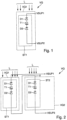
- the illustration of the Figure 1 shows a schematic view of a first embodiment with two partial voltage sources, comprising a scalable voltage source VQ with a first stack ST1 with a top side and a bottom side with a number N equal to two diodes.
- the first stack ST1 has a series connection of a first diode D1 and a first tunnel diode T1 and a second diode D2.
- a first voltage connection VSUP1 is formed on the top side of the stack ST1 and a second voltage connection VSUP2 on the bottom side of the stack ST1.
- the source voltage VQ1 of the first stack ST1 is made up of the partial voltages of the individual diodes D1 to D2.
- the first stack ST1 is exposed to a photon stream, ie the light L.
- the first stack ST1 of the diodes D1 to D2 and the tunnel diode T1 is designed as a monolithic block, preferably made of the same semiconductor material.
- FIG. 2 A further embodiment of an advantageous arrangement of the first stack ST1 and a second stack ST2 is shown. Both stacks ST1 and ST2 each have two partial voltage sources. In the following, only the differences to the illustration of the Figure 1 explained.
- the second stack ST2 like the first stack ST1, has a series connection of two diodes with tunnel diodes formed between them. Both stacks ST1 and ST2 are connected in series so that the source voltage VQ1 of the first stack ST1 and the source voltage VQ2 of the second stack ST2 add up if the two stacks ST1 and ST2 are exposed to the photon current L.
- the illustration of the Figure 3 shows a schematic view of a first embodiment not according to the invention with three partial voltage sources, comprising the scalable voltage source VQ with the first stack ST1 with the top and the bottom with the number N equal to three diodes.
- the first stack ST1 has the series connection of the first diode D1 and the first tunnel diode T1 and the second diode D2 and a second tunnel diode T2 and a third diode D3.
- the first voltage connection VSUP1 is formed on the top of the stack ST1 and the second voltage connection VSUP2 is formed on the bottom of the stack ST1.
- the source voltage VQ1 of the first stack ST1 is essentially made up of the partial voltages of the individual diodes D1 to D3.
- the first stack ST1 is exposed to the photon stream, i.e. the light L.
- the first stack ST1 of the diodes D1 to D3 and the tunnel diodes T1 and T2 is designed as a monolithic block, preferably made of the same semiconductor material.
- both stacks ST1 and ST2 each have three partial voltage sources.
- the second stack ST2 like the first stack ST1, has a series connection of three diodes with tunnel diodes in between. Both stacks ST1 and ST2 are connected in series so that the source voltage VQ1 of the first stack ST1 and the source voltage VQ2 of the second stack ST2 add up if the two stacks ST1 and ST2 are exposed to the photon current L.
- the two stacks ST1 and ST2 have a different number of diodes connected in series. In another embodiment not shown, at least the first stack ST1 and/or the second stack ST2 have more than three diodes connected in series. This allows the voltage level of the voltage source VQ to be scaled.
- the number N is preferably in a range between four and eight. In another embodiment not shown, the two stacks ST1 and ST2 are connected in parallel to one another.
- the first stack ST1 comprises a total of five partial voltage sources connected in series as diodes D1 to D5.
- the light L strikes the surface OB of the first diode D1.
- the surface OB is almost or completely illuminated.
- a tunnel diode T1-T4 is formed between each of the successive diodes D1-D5.
- the thickness of the absorption region increases, so that the lowest diode D5 has the thickest absorption region.
- the total thickness of the first stack ST1 is less than or equal to 12 ⁇ m.
- a substrate SUB is formed below the lowest diode D5.
- a first metallic connection contact K1 is formed at the edge R.
- the first connection contact K1 is connected to the first voltage connection VSUP1 - not shown.
- the substrate SUB has an upper side OS, wherein the upper side OS of the substrate SUB is integrally connected to the lowest, e.g. the fifth diode D5. It is understood that a thin nucleation layer and a buffer layer are epitaxially generated on the substrate before the lowest diode is arranged on the substrate and integrally connected to the upper side OS of the substrate.
- the upper side OS of the substrate SUB has a larger surface than the area on the underside of the first stack ST1. This forms a circumferential step STU.
- the height of the side surface of the step STU is greater than 100 nm.
- the edge of the step STU is more than 5 ⁇ m and less than 500 ⁇ m away from the immediately adjacent side surface of the first stack ST1 of the step, shown as the length of the reference symbol STU.
- a second full-surface metallic contact K2 is formed on the underside of the substrate SUB.
- the second connection contact K2 is connected to the second voltage connection VSUP2 - not shown.
Landscapes
- Electrodes Of Semiconductors (AREA)
- Photovoltaic Devices (AREA)
- Life Sciences & Earth Sciences (AREA)
- Engineering & Computer Science (AREA)
- Sustainable Energy (AREA)
- Light Receiving Elements (AREA)
- Sustainable Development (AREA)
Claims (15)
- Source de tension échelonnable (VQ), comprenant :- un nombre N de sources de tension partielles qui se présentent sous la forme de diodes semi-conductrices connectées en série les unes aux autres, dans laquelle chacune des sources de tension partielles comprend une diode semi-conductrice (D1, 02) présentant une jonction p-n, dans laquelle la diode semi-conductrice (D1, D2) présente une couche d'absorption dopée p et la diode semi-conductrice (D1, D2) présente une couche d'absorption n, dans laquelle la couche d'absorption n est passivée par une couche de passivation dopée n qui présente une bande interdite plus grande que la bande interdite de la couche d'absorption n, et dans laquelle les tensions de source partielle des différentes sources de tension partielles présentent entre elles un écart inférieur à 20 %, et- une diode tunnel (T1) qui est formée entre deux sources de tension partielles successives, dans laquelle la diode tunnel (T1) comprend plusieurs couches semi-conductrices qui présentent une bande interdite plus grande que la bande interdite des couches d'absorption p / n, et dans laquelle les couches semi-conductrices qui présentent une bande interdite plus grande sont respectivement constituées d'un matériau présentant une stoechiométrie modifiée et/ou présentant une autre composition d'éléments que les couches d'absorption p / n de la diode semi-conductrice (D1, D2),- dans laquelle les sources de tension partielles et les diodes tunnels (T1) sont intégrées les unes aux autres de façon monolithique et forment ensemble un premier empilement (ST1) qui présente une face supérieure et une face inférieure, et dans laquelle le nombre N de sources de tension partielles est exactement égal à deux,- dans laquelle, lorsque le premier empilement (ST1) est éclairé avec une lumière (L), la lumière (L) frappe la surface (OB) du premier empilement (ST1) sur la face supérieure et la taille de la surface éclairée (OB) sur la face supérieure de l'empilement correspond sensiblement à la taille de la surface du premier empilement sur la face supérieure, et dans laquelle le premier empilement (ST1) présente une épaisseur totale inférieure à 12 µm,- dans laquelle, à 300 K, le premier empilement (ST1) présente une tension de source (VQ1) supérieure à 2,2 volts, pour autant que le premier empilement (STl) soit irradié par la lumière (L), et dans laquelle, dans la direction d'incidence de la lumière, à partir de la face supérieure du premier empilement (ST1) en direction de la face inférieure de l'empilement, l'épaisseur totale des couches d'absorption p et n d'une diode semi-conductrice augmente à partir de la diode semi-conductrice supérieure (D1) en direction de la diode semi-conductrice inférieure (D2), et dans laquelle chaque couche d'absorption p de la diode semi-conductrice (D1, D2) est passivée par une couche de passivation dopée p qui présente une bande interdite plus grande que la bande interdite de la couche d'absorption p,- dans laquelle le premier empilement (ST1) est agencé sur un substrat (SUS) et le substrat (SUB) comprend un matériau semi-conducteur sur la face supérieure du premier empilement (ST1), et dans laquelle une première borne de tension (VSUP1) est formée en tant que un premier contact métallique périphérique (K1) dans le voisinage du rebord (R) ou en tant qu'unique surface de contact (K1) sur le rebord (R),- dans laquelle une face supérieure (OS) du substrat (SUB) est connectée à la diode la plus basse par l'intermédiaire d'une liaison de matière,- dans laquelle la face supérieure (OS) du substrat (SUB) présente une surface plus grande que la surface de la face inférieure du premier empilement (ST1), de telle sorte qu'un gradin périphérique (STU) soit formé dans le voisinage de la face inférieure du premier empilement (ST1) et que la face supérieure (OS) du substrat (SUB) présente une surface plus grande que la surface de la face inférieure du premier empilement (STl), et- dans laquelle une seconde borne de tension (VSUP2) est formée en tant que contact de connexion métallique K2 sur la totalité de la surface d'une face inférieure du substrat (SUB).
- Source de tension échelonnable (VQ) selon la revendication 1, caractérisée en ce que les tensions de source partielle des sources de tension partielles présentent entre elles un écart inférieur à 10 %.
- Source de tension échelonnable (VQ) selon la revendication 1 ou la revendication 2, caractérisée en ce que les diodes semi-conductrices (01, 02) sont constituées chacune du même matériau semi-conducteur.
- Source de tension échelonnable (VQ) selon l'une quelconque des revendications précédentes, caractérisée en ce que le premier empilement (ST1) présente une surface de base inférieure à 2 mm2 ou inférieure à 1 mm2.
- Source de tension échelonnable (VQ) selon la revendication 4, caractérisée en ce que la surface de base est quadrangulaire.
- Source de tension échelonnable (VQ) selon l'une quelconque des revendications précédentes, caractérisée en ce qu'un second empilement (ST2) est formé, en ce que le premier empilement (ST1) et le second empilement (ST2) sont agencés l'un à côté de l'autre sur un support commun, et en ce que les deux empilements (ST1, ST2) sont connectés l'un à l'autre en série de telle sorte que la tension de source (VQ1) du premier empilement (ST1) et la tension de source (VQ2) du second empilement (ST2) s'additionnent.
- Source de tension échelonnable (VQ) selon l'une quelconque des revendications précédentes, caractérisée en ce que le matériau semi-conducteur et/ou le substrat sont constitués de matériaux III-V.
- Source de tension échelonnable (VQ) selon l'une quelconque des revendications précédentes, caractérisée en ce que le substrat comprend du germanium ou de l'arséniure de gallium.
- Source de tension échelonnable (VQ) selon l'une quelconque des revendications précédentes, caractérisée en ce qu'un miroir semi-conducteur est formé en dessous de la diode semi-conductrice la plus basse de l'empilement.
- Source de tension échelonnable (VQ) selon l'une quelconque des revendications précédentes, caractérisée en ce que les couches semi-conductrices de l'empilement (ST1) comprennent à la fois des couches contenant de l'arséniure et des couches contenant du phosphure.
- Source de tension échelonnable (VQ) selon l'une quelconque des revendications précédentes, caractérisée en ce que le bord du rebord est distant d'au moins 5 µm et d'au plus 500 µm de la face latérale immédiatement adjacente de l'empilement.
- Source de tension échelonnable (VQ) selon l'une quelconque des revendications précédentes, caractérisée en ce qu'une couche intrinsèque est formée entre la couche d'absorption p et la couche d'absorption n pour au moins une diode semi-conductrice.
- Source de tension échelonnable (VQ) selon la revendication 12, caractérisée en ce que la couche intrinsèque est formée sur la diode semi-conductrice la plus basse.
- Source de tension échelonnable (VQ) selon la revendication 12, caractérisée en ce que la couche intrinsèque est formée sur la totalité des diodes semi-conductrices.
- Source de tension échelonnable (VQ) selon l'une quelconque des revendications précédentes, caractérisée en ce que les deux diodes semi-conductrices sont agencées sur un substrat de germanium, et en ce que les diodes semi-conductrices présentent chacune comme matériau d'absorption un composé InGaAs dont le réseau est adapté au substrat de germanium.
Applications Claiming Priority (1)
| Application Number | Priority Date | Filing Date | Title |
|---|---|---|---|
| DE102015012007.7A DE102015012007A1 (de) | 2015-09-19 | 2015-09-19 | Skalierbare Spannungsquelle |
Publications (2)
| Publication Number | Publication Date |
|---|---|
| EP3144982A1 EP3144982A1 (fr) | 2017-03-22 |
| EP3144982B1 true EP3144982B1 (fr) | 2024-05-15 |
Family
ID=56855249
Family Applications (1)
| Application Number | Title | Priority Date | Filing Date |
|---|---|---|---|
| EP16001926.1A Active EP3144982B1 (fr) | 2015-09-19 | 2016-09-02 | Source de tension échelonnable |
Country Status (7)
| Country | Link |
|---|---|
| US (1) | US9741874B2 (fr) |
| EP (1) | EP3144982B1 (fr) |
| JP (1) | JP6341965B2 (fr) |
| KR (1) | KR101905262B1 (fr) |
| CN (1) | CN107039555B (fr) |
| DE (1) | DE102015012007A1 (fr) |
| TW (1) | TWI605608B (fr) |
Families Citing this family (5)
| Publication number | Priority date | Publication date | Assignee | Title |
|---|---|---|---|---|
| DE102016001387A1 (de) * | 2016-02-09 | 2017-08-10 | Azur Space Solar Power Gmbh | Empfängerbaustein |
| DE102016013749A1 (de) * | 2016-11-18 | 2018-05-24 | Azur Space Solar Power Gmbh | Stapelförmige Halbleiterstruktur |
| US20200144433A1 (en) * | 2017-06-23 | 2020-05-07 | University Of Ottawa | Photovoltaic device |
| JP6911574B2 (ja) * | 2017-06-27 | 2021-07-28 | 株式会社豊田中央研究所 | シリコン光電荷分離素子 |
| DE102017011643B4 (de) * | 2017-12-15 | 2020-05-14 | Azur Space Solar Power Gmbh | Optische Spannungsquelle |
Citations (6)
| Publication number | Priority date | Publication date | Assignee | Title |
|---|---|---|---|---|
| JP2008177212A (ja) * | 2007-01-16 | 2008-07-31 | Nec Corp | 半導体受光素子 |
| WO2012104421A1 (fr) * | 2011-02-04 | 2012-08-09 | Azur Space Solar Power Gmbh | Cellule solaire à jonctions multiples et procédé de fabrication d'une telle cellule |
| CN102651416A (zh) * | 2012-05-18 | 2012-08-29 | 中国科学院苏州纳米技术与纳米仿生研究所 | 三结叠层GaAs激光光伏电池及其制备方法 |
| US20120266803A1 (en) * | 2008-10-17 | 2012-10-25 | Zediker Mark S | High power laser photo-conversion assemblies, apparatuses and methods of use |
| US20150221803A1 (en) * | 2014-02-05 | 2015-08-06 | Solar Junction Corporation | Monolithic multijunction power converter |
| DE102015007326B3 (de) * | 2015-06-12 | 2016-07-21 | Azur Space Solar Power Gmbh | Optokoppler |
Family Cites Families (16)
| Publication number | Priority date | Publication date | Assignee | Title |
|---|---|---|---|---|
| NL259446A (fr) * | 1959-12-30 | 1900-01-01 | ||
| US4127862A (en) | 1977-09-06 | 1978-11-28 | Bell Telephone Laboratories, Incorporated | Integrated optical detectors |
| JPS6284570A (ja) * | 1985-06-07 | 1987-04-18 | エレクトリツク パワ− リサ−チ インスチテユ−ト インコ−ポレ−テツド | 光電池デバイス |
| JPH0472773A (ja) * | 1990-07-13 | 1992-03-06 | Hitachi Cable Ltd | 多層接合型太陽電池 |
| US6239354B1 (en) | 1998-10-09 | 2001-05-29 | Midwest Research Institute | Electrical isolation of component cells in monolithically interconnected modules |
| CA2437124A1 (fr) * | 2001-02-09 | 2002-08-22 | Midwest Research Institute | Co-dopage isoelectronique |
| US7202102B2 (en) * | 2001-11-27 | 2007-04-10 | Jds Uniphase Corporation | Doped absorption for enhanced responsivity for high speed photodiodes |
| US20060048811A1 (en) * | 2004-09-09 | 2006-03-09 | Krut Dimitri D | Multijunction laser power converter |
| US7687707B2 (en) * | 2005-11-16 | 2010-03-30 | Emcore Solar Power, Inc. | Via structures in solar cells with bypass diode |
| US8742251B2 (en) * | 2006-12-20 | 2014-06-03 | Jds Uniphase Corporation | Multi-segment photovoltaic power converter with a center portion |
| CN102449775B (zh) * | 2009-06-05 | 2014-07-02 | 独立行政法人产业技术综合研究所 | 半导体基板、光电转换器件、半导体基板的制造方法和光电转换器件的制造方法 |
| DE102010001420A1 (de) | 2010-02-01 | 2011-08-04 | Robert Bosch GmbH, 70469 | III-V-Halbleiter-Solarzelle |
| WO2013074530A2 (fr) * | 2011-11-15 | 2013-05-23 | Solar Junction Corporation | Cellules solaires à jonctions multiples à haute efficacité |
| JP2013115414A (ja) * | 2011-12-01 | 2013-06-10 | Sharp Corp | 化合物半導体太陽電池セル |
| WO2015085422A1 (fr) * | 2013-12-09 | 2015-06-18 | Azastra Opto Inc. | Transducteur de conversion d'énergie optique en énergie électrique |
| DE102015006379B4 (de) | 2015-05-18 | 2022-03-17 | Azur Space Solar Power Gmbh | Skalierbare Spannungsquelle |
-
2015
- 2015-09-19 DE DE102015012007.7A patent/DE102015012007A1/de not_active Withdrawn
-
2016
- 2016-09-02 EP EP16001926.1A patent/EP3144982B1/fr active Active
- 2016-09-09 TW TW105129250A patent/TWI605608B/zh active
- 2016-09-09 KR KR1020160116411A patent/KR101905262B1/ko active Active
- 2016-09-16 JP JP2016181317A patent/JP6341965B2/ja active Active
- 2016-09-18 CN CN201610829033.6A patent/CN107039555B/zh active Active
- 2016-09-19 US US15/268,884 patent/US9741874B2/en active Active
Patent Citations (7)
| Publication number | Priority date | Publication date | Assignee | Title |
|---|---|---|---|---|
| JP2008177212A (ja) * | 2007-01-16 | 2008-07-31 | Nec Corp | 半導体受光素子 |
| US20120266803A1 (en) * | 2008-10-17 | 2012-10-25 | Zediker Mark S | High power laser photo-conversion assemblies, apparatuses and methods of use |
| WO2012104421A1 (fr) * | 2011-02-04 | 2012-08-09 | Azur Space Solar Power Gmbh | Cellule solaire à jonctions multiples et procédé de fabrication d'une telle cellule |
| CN102651416A (zh) * | 2012-05-18 | 2012-08-29 | 中国科学院苏州纳米技术与纳米仿生研究所 | 三结叠层GaAs激光光伏电池及其制备方法 |
| US20150221803A1 (en) * | 2014-02-05 | 2015-08-06 | Solar Junction Corporation | Monolithic multijunction power converter |
| DE102015007326B3 (de) * | 2015-06-12 | 2016-07-21 | Azur Space Solar Power Gmbh | Optokoppler |
| EP3104422A1 (fr) * | 2015-06-12 | 2016-12-14 | AZUR SPACE Solar Power GmbH | Optocoupleur |
Non-Patent Citations (2)
| Title |
|---|
| ANDREAS W. BETT ET AL: "III-V solar cells under monochromatic illumination", 2008 33RD IEEE PHOTOVOLATIC SPECIALISTS CONFERENCE, 1 May 2008 (2008-05-01), pages 1 - 5, XP055103509, ISSN: 0160-8371, ISBN: 978-1-42-441640-0, DOI: 10.1109/PVSC.2008.4922910 * |
| WILKINS MATTHEW ET AL: "Performance impact of luminescent coupling on monolithic 12-junction phototransducers for 12 V photonic power systems", PROCEEDINGS OF SPIE; [PROCEEDINGS OF SPIE ISSN 0277-786X VOLUME 10524], SPIE, US, vol. 9743, 14 March 2016 (2016-03-14), pages 97430W - 97430W, XP060067383, ISBN: 978-1-5106-1533-5, DOI: 10.1117/12.2213727 * |
Also Published As
| Publication number | Publication date |
|---|---|
| KR101905262B1 (ko) | 2018-10-05 |
| TWI605608B (zh) | 2017-11-11 |
| JP6341965B2 (ja) | 2018-06-13 |
| CN107039555A (zh) | 2017-08-11 |
| US9741874B2 (en) | 2017-08-22 |
| CN107039555B (zh) | 2020-11-27 |
| JP2017063191A (ja) | 2017-03-30 |
| EP3144982A1 (fr) | 2017-03-22 |
| KR20170034769A (ko) | 2017-03-29 |
| US20170084757A1 (en) | 2017-03-23 |
| TW201721897A (zh) | 2017-06-16 |
| DE102015012007A1 (de) | 2017-03-23 |
Similar Documents
| Publication | Publication Date | Title |
|---|---|---|
| EP3104422B1 (fr) | Optocoupleur | |
| EP3144982B1 (fr) | Source de tension échelonnable | |
| DE102008034711B4 (de) | Invertierte metamorphe Multijunction-Solarzelle mit Barrierenschicht und Verfahren zur Herstellung | |
| DE102010012080B4 (de) | Herstellungsverfahren einer invertierten Multijunction-Solarzelle mit GeSiSn und invertierte Multijunction-Solarzelle mit GeSiSn | |
| EP3096361B1 (fr) | Source de tension echelonnable | |
| EP2936566A1 (fr) | Cellule photovoltaïque tolérant l'ajustement | |
| EP3557632A1 (fr) | Diode semi-conductrice iii-v à base de gaas | |
| DE2607005C2 (de) | Integrierte Tandem-Solarzelle | |
| EP3082170B1 (fr) | Composant optocoupleur empilé | |
| EP3324451A1 (fr) | Structure semi-conductrice en forme d'empilement | |
| EP3185312A1 (fr) | Cellule solaire multi-jonctions disposées en piles | |
| DE69005048T2 (de) | Matrix von Heteroübergang-Photodioden. | |
| EP3012874A1 (fr) | Cellule solaire à jonctions multiples intégrée en forme de pile | |
| EP3065177B1 (fr) | Dispositif de cellules solaires | |
| DE102015013514B4 (de) | Optischer Empfängerbaustein | |
| DE102013211231B4 (de) | Verfahren zum Bilden einer Tandem-Fotovoltaikeinheit | |
| EP3965168B1 (fr) | Cellule solaire multiple monolithique empilée | |
| EP3411909A1 (fr) | Module de réception | |
| DE102016005640A1 (de) | Invertierte Mehrfach-Solarzelle | |
| DE102010018548A1 (de) | Dünnschicht-Solarzellenmodul mit in Reihe geschalteten Solarzellen | |
| EP3965169B1 (fr) | Cellule solaire multiple monolithique empilée | |
| WO2014122308A1 (fr) | Cellule solaire à multi-jonction, procédé de fabrication et utilisations | |
| EP2991124A1 (fr) | Cellule solaire multiple intégrée en forme de pile et procédé de fabrication d'une cellule solaire multiple intégrée en forme de pile | |
| EP2671257A2 (fr) | Ensemble photovoltaïque | |
| DE102023002091A1 (de) | lll-V Photovoltaik Mehrfachsolarzelle |
Legal Events
| Date | Code | Title | Description |
|---|---|---|---|
| PUAI | Public reference made under article 153(3) epc to a published international application that has entered the european phase |
Free format text: ORIGINAL CODE: 0009012 |
|
| STAA | Information on the status of an ep patent application or granted ep patent |
Free format text: STATUS: THE APPLICATION HAS BEEN PUBLISHED |
|
| AK | Designated contracting states |
Kind code of ref document: A1 Designated state(s): AL AT BE BG CH CY CZ DE DK EE ES FI FR GB GR HR HU IE IS IT LI LT LU LV MC MK MT NL NO PL PT RO RS SE SI SK SM TR |
|
| AX | Request for extension of the european patent |
Extension state: BA ME |
|
| STAA | Information on the status of an ep patent application or granted ep patent |
Free format text: STATUS: REQUEST FOR EXAMINATION WAS MADE |
|
| 17P | Request for examination filed |
Effective date: 20170330 |
|
| RBV | Designated contracting states (corrected) |
Designated state(s): AL AT BE BG CH CY CZ DE DK EE ES FI FR GB GR HR HU IE IS IT LI LT LU LV MC MK MT NL NO PL PT RO RS SE SI SK SM TR |
|
| STAA | Information on the status of an ep patent application or granted ep patent |
Free format text: STATUS: EXAMINATION IS IN PROGRESS |
|
| 17Q | First examination report despatched |
Effective date: 20200909 |
|
| GRAP | Despatch of communication of intention to grant a patent |
Free format text: ORIGINAL CODE: EPIDOSNIGR1 |
|
| STAA | Information on the status of an ep patent application or granted ep patent |
Free format text: STATUS: GRANT OF PATENT IS INTENDED |
|
| GRAS | Grant fee paid |
Free format text: ORIGINAL CODE: EPIDOSNIGR3 |
|
| INTG | Intention to grant announced |
Effective date: 20240305 |
|
| GRAA | (expected) grant |
Free format text: ORIGINAL CODE: 0009210 |
|
| STAA | Information on the status of an ep patent application or granted ep patent |
Free format text: STATUS: THE PATENT HAS BEEN GRANTED |
|
| AK | Designated contracting states |
Kind code of ref document: B1 Designated state(s): AL AT BE BG CH CY CZ DE DK EE ES FI FR GB GR HR HU IE IS IT LI LT LU LV MC MK MT NL NO PL PT RO RS SE SI SK SM TR |
|
| REG | Reference to a national code |
Ref country code: CH Ref legal event code: EP Ref country code: GB Ref legal event code: FG4D Free format text: NOT ENGLISH |
|
| REG | Reference to a national code |
Ref country code: IE Ref legal event code: FG4D Free format text: LANGUAGE OF EP DOCUMENT: GERMAN |
|
| REG | Reference to a national code |
Ref country code: DE Ref legal event code: R096 Ref document number: 502016016533 Country of ref document: DE |
|
| P01 | Opt-out of the competence of the unified patent court (upc) registered |
Free format text: CASE NUMBER: APP_40466/2024 Effective date: 20240708 |
|
| REG | Reference to a national code |
Ref country code: LT Ref legal event code: MG9D |
|
| REG | Reference to a national code |
Ref country code: NL Ref legal event code: MP Effective date: 20240515 |
|
| PG25 | Lapsed in a contracting state [announced via postgrant information from national office to epo] |
Ref country code: IS Free format text: LAPSE BECAUSE OF FAILURE TO SUBMIT A TRANSLATION OF THE DESCRIPTION OR TO PAY THE FEE WITHIN THE PRESCRIBED TIME-LIMIT Effective date: 20240915 |
|
| PG25 | Lapsed in a contracting state [announced via postgrant information from national office to epo] |
Ref country code: BG Free format text: LAPSE BECAUSE OF FAILURE TO SUBMIT A TRANSLATION OF THE DESCRIPTION OR TO PAY THE FEE WITHIN THE PRESCRIBED TIME-LIMIT Effective date: 20240515 |
|
| PG25 | Lapsed in a contracting state [announced via postgrant information from national office to epo] |
Ref country code: HR Free format text: LAPSE BECAUSE OF FAILURE TO SUBMIT A TRANSLATION OF THE DESCRIPTION OR TO PAY THE FEE WITHIN THE PRESCRIBED TIME-LIMIT Effective date: 20240515 Ref country code: FI Free format text: LAPSE BECAUSE OF FAILURE TO SUBMIT A TRANSLATION OF THE DESCRIPTION OR TO PAY THE FEE WITHIN THE PRESCRIBED TIME-LIMIT Effective date: 20240515 |
|
| PG25 | Lapsed in a contracting state [announced via postgrant information from national office to epo] |
Ref country code: GR Free format text: LAPSE BECAUSE OF FAILURE TO SUBMIT A TRANSLATION OF THE DESCRIPTION OR TO PAY THE FEE WITHIN THE PRESCRIBED TIME-LIMIT Effective date: 20240816 |
|
| PG25 | Lapsed in a contracting state [announced via postgrant information from national office to epo] |
Ref country code: PT Free format text: LAPSE BECAUSE OF FAILURE TO SUBMIT A TRANSLATION OF THE DESCRIPTION OR TO PAY THE FEE WITHIN THE PRESCRIBED TIME-LIMIT Effective date: 20240916 |
|
| PG25 | Lapsed in a contracting state [announced via postgrant information from national office to epo] |
Ref country code: NL Free format text: LAPSE BECAUSE OF FAILURE TO SUBMIT A TRANSLATION OF THE DESCRIPTION OR TO PAY THE FEE WITHIN THE PRESCRIBED TIME-LIMIT Effective date: 20240515 |
|
| PG25 | Lapsed in a contracting state [announced via postgrant information from national office to epo] |
Ref country code: ES Free format text: LAPSE BECAUSE OF FAILURE TO SUBMIT A TRANSLATION OF THE DESCRIPTION OR TO PAY THE FEE WITHIN THE PRESCRIBED TIME-LIMIT Effective date: 20240515 |
|
| PG25 | Lapsed in a contracting state [announced via postgrant information from national office to epo] |
Ref country code: PL Free format text: LAPSE BECAUSE OF FAILURE TO SUBMIT A TRANSLATION OF THE DESCRIPTION OR TO PAY THE FEE WITHIN THE PRESCRIBED TIME-LIMIT Effective date: 20240515 |
|
| PG25 | Lapsed in a contracting state [announced via postgrant information from national office to epo] |
Ref country code: LV Free format text: LAPSE BECAUSE OF FAILURE TO SUBMIT A TRANSLATION OF THE DESCRIPTION OR TO PAY THE FEE WITHIN THE PRESCRIBED TIME-LIMIT Effective date: 20240515 |
|
| PG25 | Lapsed in a contracting state [announced via postgrant information from national office to epo] |
Ref country code: PT Free format text: LAPSE BECAUSE OF FAILURE TO SUBMIT A TRANSLATION OF THE DESCRIPTION OR TO PAY THE FEE WITHIN THE PRESCRIBED TIME-LIMIT Effective date: 20240916 Ref country code: PL Free format text: LAPSE BECAUSE OF FAILURE TO SUBMIT A TRANSLATION OF THE DESCRIPTION OR TO PAY THE FEE WITHIN THE PRESCRIBED TIME-LIMIT Effective date: 20240515 Ref country code: NO Free format text: LAPSE BECAUSE OF FAILURE TO SUBMIT A TRANSLATION OF THE DESCRIPTION OR TO PAY THE FEE WITHIN THE PRESCRIBED TIME-LIMIT Effective date: 20240815 Ref country code: NL Free format text: LAPSE BECAUSE OF FAILURE TO SUBMIT A TRANSLATION OF THE DESCRIPTION OR TO PAY THE FEE WITHIN THE PRESCRIBED TIME-LIMIT Effective date: 20240515 Ref country code: LV Free format text: LAPSE BECAUSE OF FAILURE TO SUBMIT A TRANSLATION OF THE DESCRIPTION OR TO PAY THE FEE WITHIN THE PRESCRIBED TIME-LIMIT Effective date: 20240515 Ref country code: IS Free format text: LAPSE BECAUSE OF FAILURE TO SUBMIT A TRANSLATION OF THE DESCRIPTION OR TO PAY THE FEE WITHIN THE PRESCRIBED TIME-LIMIT Effective date: 20240915 Ref country code: HR Free format text: LAPSE BECAUSE OF FAILURE TO SUBMIT A TRANSLATION OF THE DESCRIPTION OR TO PAY THE FEE WITHIN THE PRESCRIBED TIME-LIMIT Effective date: 20240515 Ref country code: GR Free format text: LAPSE BECAUSE OF FAILURE TO SUBMIT A TRANSLATION OF THE DESCRIPTION OR TO PAY THE FEE WITHIN THE PRESCRIBED TIME-LIMIT Effective date: 20240816 Ref country code: FI Free format text: LAPSE BECAUSE OF FAILURE TO SUBMIT A TRANSLATION OF THE DESCRIPTION OR TO PAY THE FEE WITHIN THE PRESCRIBED TIME-LIMIT Effective date: 20240515 Ref country code: ES Free format text: LAPSE BECAUSE OF FAILURE TO SUBMIT A TRANSLATION OF THE DESCRIPTION OR TO PAY THE FEE WITHIN THE PRESCRIBED TIME-LIMIT Effective date: 20240515 Ref country code: BG Free format text: LAPSE BECAUSE OF FAILURE TO SUBMIT A TRANSLATION OF THE DESCRIPTION OR TO PAY THE FEE WITHIN THE PRESCRIBED TIME-LIMIT Effective date: 20240515 Ref country code: RS Free format text: LAPSE BECAUSE OF FAILURE TO SUBMIT A TRANSLATION OF THE DESCRIPTION OR TO PAY THE FEE WITHIN THE PRESCRIBED TIME-LIMIT Effective date: 20240815 |
|
| REG | Reference to a national code |
Ref country code: DE Ref legal event code: R079 Ref document number: 502016016533 Country of ref document: DE Free format text: PREVIOUS MAIN CLASS: H01L0031068700 Ipc: H10F0010142000 |
|
| PG25 | Lapsed in a contracting state [announced via postgrant information from national office to epo] |
Ref country code: DK Free format text: LAPSE BECAUSE OF FAILURE TO SUBMIT A TRANSLATION OF THE DESCRIPTION OR TO PAY THE FEE WITHIN THE PRESCRIBED TIME-LIMIT Effective date: 20240515 |
|
| PG25 | Lapsed in a contracting state [announced via postgrant information from national office to epo] |
Ref country code: EE Free format text: LAPSE BECAUSE OF FAILURE TO SUBMIT A TRANSLATION OF THE DESCRIPTION OR TO PAY THE FEE WITHIN THE PRESCRIBED TIME-LIMIT Effective date: 20240515 |
|
| PG25 | Lapsed in a contracting state [announced via postgrant information from national office to epo] |
Ref country code: CZ Free format text: LAPSE BECAUSE OF FAILURE TO SUBMIT A TRANSLATION OF THE DESCRIPTION OR TO PAY THE FEE WITHIN THE PRESCRIBED TIME-LIMIT Effective date: 20240515 |
|
| PG25 | Lapsed in a contracting state [announced via postgrant information from national office to epo] |
Ref country code: SK Free format text: LAPSE BECAUSE OF FAILURE TO SUBMIT A TRANSLATION OF THE DESCRIPTION OR TO PAY THE FEE WITHIN THE PRESCRIBED TIME-LIMIT Effective date: 20240515 Ref country code: RO Free format text: LAPSE BECAUSE OF FAILURE TO SUBMIT A TRANSLATION OF THE DESCRIPTION OR TO PAY THE FEE WITHIN THE PRESCRIBED TIME-LIMIT Effective date: 20240515 |
|
| PG25 | Lapsed in a contracting state [announced via postgrant information from national office to epo] |
Ref country code: SM Free format text: LAPSE BECAUSE OF FAILURE TO SUBMIT A TRANSLATION OF THE DESCRIPTION OR TO PAY THE FEE WITHIN THE PRESCRIBED TIME-LIMIT Effective date: 20240515 |
|
| PG25 | Lapsed in a contracting state [announced via postgrant information from national office to epo] |
Ref country code: SM Free format text: LAPSE BECAUSE OF FAILURE TO SUBMIT A TRANSLATION OF THE DESCRIPTION OR TO PAY THE FEE WITHIN THE PRESCRIBED TIME-LIMIT Effective date: 20240515 Ref country code: SK Free format text: LAPSE BECAUSE OF FAILURE TO SUBMIT A TRANSLATION OF THE DESCRIPTION OR TO PAY THE FEE WITHIN THE PRESCRIBED TIME-LIMIT Effective date: 20240515 Ref country code: RO Free format text: LAPSE BECAUSE OF FAILURE TO SUBMIT A TRANSLATION OF THE DESCRIPTION OR TO PAY THE FEE WITHIN THE PRESCRIBED TIME-LIMIT Effective date: 20240515 Ref country code: EE Free format text: LAPSE BECAUSE OF FAILURE TO SUBMIT A TRANSLATION OF THE DESCRIPTION OR TO PAY THE FEE WITHIN THE PRESCRIBED TIME-LIMIT Effective date: 20240515 Ref country code: DK Free format text: LAPSE BECAUSE OF FAILURE TO SUBMIT A TRANSLATION OF THE DESCRIPTION OR TO PAY THE FEE WITHIN THE PRESCRIBED TIME-LIMIT Effective date: 20240515 Ref country code: CZ Free format text: LAPSE BECAUSE OF FAILURE TO SUBMIT A TRANSLATION OF THE DESCRIPTION OR TO PAY THE FEE WITHIN THE PRESCRIBED TIME-LIMIT Effective date: 20240515 |
|
| PG25 | Lapsed in a contracting state [announced via postgrant information from national office to epo] |
Ref country code: IT Free format text: LAPSE BECAUSE OF FAILURE TO SUBMIT A TRANSLATION OF THE DESCRIPTION OR TO PAY THE FEE WITHIN THE PRESCRIBED TIME-LIMIT Effective date: 20240515 |
|
| REG | Reference to a national code |
Ref country code: DE Ref legal event code: R097 Ref document number: 502016016533 Country of ref document: DE |
|
| PLBE | No opposition filed within time limit |
Free format text: ORIGINAL CODE: 0009261 |
|
| STAA | Information on the status of an ep patent application or granted ep patent |
Free format text: STATUS: NO OPPOSITION FILED WITHIN TIME LIMIT |
|
| 26N | No opposition filed |
Effective date: 20250218 |
|
| PG25 | Lapsed in a contracting state [announced via postgrant information from national office to epo] |
Ref country code: SI Free format text: LAPSE BECAUSE OF FAILURE TO SUBMIT A TRANSLATION OF THE DESCRIPTION OR TO PAY THE FEE WITHIN THE PRESCRIBED TIME-LIMIT Effective date: 20240515 Ref country code: MC Free format text: LAPSE BECAUSE OF FAILURE TO SUBMIT A TRANSLATION OF THE DESCRIPTION OR TO PAY THE FEE WITHIN THE PRESCRIBED TIME-LIMIT Effective date: 20240515 |
|
| REG | Reference to a national code |
Ref country code: CH Ref legal event code: PL |
|
| PG25 | Lapsed in a contracting state [announced via postgrant information from national office to epo] |
Ref country code: LU Free format text: LAPSE BECAUSE OF NON-PAYMENT OF DUE FEES Effective date: 20240902 |
|
| REG | Reference to a national code |
Ref country code: BE Ref legal event code: MM Effective date: 20240930 |
|
| PG25 | Lapsed in a contracting state [announced via postgrant information from national office to epo] |
Ref country code: BE Free format text: LAPSE BECAUSE OF NON-PAYMENT OF DUE FEES Effective date: 20240930 |
|
| PG25 | Lapsed in a contracting state [announced via postgrant information from national office to epo] |
Ref country code: CH Free format text: LAPSE BECAUSE OF NON-PAYMENT OF DUE FEES Effective date: 20240930 |
|
| PG25 | Lapsed in a contracting state [announced via postgrant information from national office to epo] |
Ref country code: IE Free format text: LAPSE BECAUSE OF NON-PAYMENT OF DUE FEES Effective date: 20240902 |
|
| PG25 | Lapsed in a contracting state [announced via postgrant information from national office to epo] |
Ref country code: SE Free format text: LAPSE BECAUSE OF FAILURE TO SUBMIT A TRANSLATION OF THE DESCRIPTION OR TO PAY THE FEE WITHIN THE PRESCRIBED TIME-LIMIT Effective date: 20240515 |
|
| PGFP | Annual fee paid to national office [announced via postgrant information from national office to epo] |
Ref country code: DE Payment date: 20250919 Year of fee payment: 10 |
|
| PGFP | Annual fee paid to national office [announced via postgrant information from national office to epo] |
Ref country code: GB Payment date: 20250919 Year of fee payment: 10 |
|
| PGFP | Annual fee paid to national office [announced via postgrant information from national office to epo] |
Ref country code: FR Payment date: 20250922 Year of fee payment: 10 |
|
| REG | Reference to a national code |
Ref country code: AT Ref legal event code: MM01 Ref document number: 1687629 Country of ref document: AT Kind code of ref document: T Effective date: 20240902 |
|
| PG25 | Lapsed in a contracting state [announced via postgrant information from national office to epo] |
Ref country code: AT Free format text: LAPSE BECAUSE OF NON-PAYMENT OF DUE FEES Effective date: 20240902 |
|
| PG25 | Lapsed in a contracting state [announced via postgrant information from national office to epo] |
Ref country code: CY Free format text: LAPSE BECAUSE OF FAILURE TO SUBMIT A TRANSLATION OF THE DESCRIPTION OR TO PAY THE FEE WITHIN THE PRESCRIBED TIME-LIMIT; INVALID AB INITIO Effective date: 20160902 |
|
| PG25 | Lapsed in a contracting state [announced via postgrant information from national office to epo] |
Ref country code: HU Free format text: LAPSE BECAUSE OF FAILURE TO SUBMIT A TRANSLATION OF THE DESCRIPTION OR TO PAY THE FEE WITHIN THE PRESCRIBED TIME-LIMIT; INVALID AB INITIO Effective date: 20160902 |