EP3145033B1 - Konfektioniertes elektrisches kabel - Google Patents
Konfektioniertes elektrisches kabel Download PDFInfo
- Publication number
- EP3145033B1 EP3145033B1 EP15185351.2A EP15185351A EP3145033B1 EP 3145033 B1 EP3145033 B1 EP 3145033B1 EP 15185351 A EP15185351 A EP 15185351A EP 3145033 B1 EP3145033 B1 EP 3145033B1
- Authority
- EP
- European Patent Office
- Prior art keywords
- contact element
- electrical
- support
- cable
- electrical cable
- Prior art date
- Legal status (The legal status is an assumption and is not a legal conclusion. Google has not performed a legal analysis and makes no representation as to the accuracy of the status listed.)
- Active
Links
Images
Classifications
-
- H—ELECTRICITY
- H01—ELECTRIC ELEMENTS
- H01R—ELECTRICALLY-CONDUCTIVE CONNECTIONS; STRUCTURAL ASSOCIATIONS OF A PLURALITY OF MUTUALLY-INSULATED ELECTRICAL CONNECTING ELEMENTS; COUPLING DEVICES; CURRENT COLLECTORS
- H01R13/00—Details of coupling devices of the kinds covered by groups H01R12/70 or H01R24/00 - H01R33/00
- H01R13/40—Securing contact members in or to a base or case; Insulating of contact members
-
- H—ELECTRICITY
- H01—ELECTRIC ELEMENTS
- H01R—ELECTRICALLY-CONDUCTIVE CONNECTIONS; STRUCTURAL ASSOCIATIONS OF A PLURALITY OF MUTUALLY-INSULATED ELECTRICAL CONNECTING ELEMENTS; COUPLING DEVICES; CURRENT COLLECTORS
- H01R24/00—Two-part coupling devices, or either of their cooperating parts, characterised by their overall structure
- H01R24/20—Coupling parts carrying sockets, clips or analogous contacts and secured only to wire or cable
-
- H—ELECTRICITY
- H01—ELECTRIC ELEMENTS
- H01R—ELECTRICALLY-CONDUCTIVE CONNECTIONS; STRUCTURAL ASSOCIATIONS OF A PLURALITY OF MUTUALLY-INSULATED ELECTRICAL CONNECTING ELEMENTS; COUPLING DEVICES; CURRENT COLLECTORS
- H01R13/00—Details of coupling devices of the kinds covered by groups H01R12/70 or H01R24/00 - H01R33/00
- H01R13/02—Contact members
-
- H—ELECTRICITY
- H01—ELECTRIC ELEMENTS
- H01R—ELECTRICALLY-CONDUCTIVE CONNECTIONS; STRUCTURAL ASSOCIATIONS OF A PLURALITY OF MUTUALLY-INSULATED ELECTRICAL CONNECTING ELEMENTS; COUPLING DEVICES; CURRENT COLLECTORS
- H01R13/00—Details of coupling devices of the kinds covered by groups H01R12/70 or H01R24/00 - H01R33/00
- H01R13/40—Securing contact members in or to a base or case; Insulating of contact members
- H01R13/42—Securing in a demountable manner
- H01R13/436—Securing a plurality of contact members by one locking piece or operation
-
- H—ELECTRICITY
- H01—ELECTRIC ELEMENTS
- H01R—ELECTRICALLY-CONDUCTIVE CONNECTIONS; STRUCTURAL ASSOCIATIONS OF A PLURALITY OF MUTUALLY-INSULATED ELECTRICAL CONNECTING ELEMENTS; COUPLING DEVICES; CURRENT COLLECTORS
- H01R13/00—Details of coupling devices of the kinds covered by groups H01R12/70 or H01R24/00 - H01R33/00
- H01R13/648—Protective earth or shield arrangements on coupling devices, e.g. anti-static shielding
- H01R13/658—High frequency shielding arrangements, e.g. against EMI [Electro-Magnetic Interference] or EMP [Electro-Magnetic Pulse]
- H01R13/6581—Shield structure
-
- H—ELECTRICITY
- H01—ELECTRIC ELEMENTS
- H01R—ELECTRICALLY-CONDUCTIVE CONNECTIONS; STRUCTURAL ASSOCIATIONS OF A PLURALITY OF MUTUALLY-INSULATED ELECTRICAL CONNECTING ELEMENTS; COUPLING DEVICES; CURRENT COLLECTORS
- H01R13/00—Details of coupling devices of the kinds covered by groups H01R12/70 or H01R24/00 - H01R33/00
- H01R13/648—Protective earth or shield arrangements on coupling devices, e.g. anti-static shielding
- H01R13/658—High frequency shielding arrangements, e.g. against EMI [Electro-Magnetic Interference] or EMP [Electro-Magnetic Pulse]
- H01R13/6591—Specific features or arrangements of connection of shield to conductive members
- H01R13/65912—Specific features or arrangements of connection of shield to conductive members for shielded multiconductor cable
-
- H—ELECTRICITY
- H01—ELECTRIC ELEMENTS
- H01R—ELECTRICALLY-CONDUCTIVE CONNECTIONS; STRUCTURAL ASSOCIATIONS OF A PLURALITY OF MUTUALLY-INSULATED ELECTRICAL CONNECTING ELEMENTS; COUPLING DEVICES; CURRENT COLLECTORS
- H01R24/00—Two-part coupling devices, or either of their cooperating parts, characterised by their overall structure
-
- H—ELECTRICITY
- H01—ELECTRIC ELEMENTS
- H01R—ELECTRICALLY-CONDUCTIVE CONNECTIONS; STRUCTURAL ASSOCIATIONS OF A PLURALITY OF MUTUALLY-INSULATED ELECTRICAL CONNECTING ELEMENTS; COUPLING DEVICES; CURRENT COLLECTORS
- H01R43/00—Apparatus or processes specially adapted for manufacturing, assembling, maintaining, or repairing of line connectors or current collectors or for joining electric conductors
- H01R43/20—Apparatus or processes specially adapted for manufacturing, assembling, maintaining, or repairing of line connectors or current collectors or for joining electric conductors for assembling or disassembling contact members with insulating base, case or sleeve
-
- H—ELECTRICITY
- H01—ELECTRIC ELEMENTS
- H01R—ELECTRICALLY-CONDUCTIVE CONNECTIONS; STRUCTURAL ASSOCIATIONS OF A PLURALITY OF MUTUALLY-INSULATED ELECTRICAL CONNECTING ELEMENTS; COUPLING DEVICES; CURRENT COLLECTORS
- H01R13/00—Details of coupling devices of the kinds covered by groups H01R12/70 or H01R24/00 - H01R33/00
- H01R13/02—Contact members
- H01R13/03—Contact members characterised by the material, e.g. plating, or coating materials
-
- H—ELECTRICITY
- H01—ELECTRIC ELEMENTS
- H01R—ELECTRICALLY-CONDUCTIVE CONNECTIONS; STRUCTURAL ASSOCIATIONS OF A PLURALITY OF MUTUALLY-INSULATED ELECTRICAL CONNECTING ELEMENTS; COUPLING DEVICES; CURRENT COLLECTORS
- H01R13/00—Details of coupling devices of the kinds covered by groups H01R12/70 or H01R24/00 - H01R33/00
- H01R13/46—Bases; Cases
- H01R13/502—Bases; Cases composed of different pieces
-
- H—ELECTRICITY
- H01—ELECTRIC ELEMENTS
- H01R—ELECTRICALLY-CONDUCTIVE CONNECTIONS; STRUCTURAL ASSOCIATIONS OF A PLURALITY OF MUTUALLY-INSULATED ELECTRICAL CONNECTING ELEMENTS; COUPLING DEVICES; CURRENT COLLECTORS
- H01R2107/00—Four or more poles
Definitions
- the invention relates to a prefabricated electrical cable according to the preamble of claim 1 and a method for producing such a cable according to claim 14.
- a prefabricated electrical cable of the type mentioned comprises at least one core, in particular a plurality of cores, wherein a respective core has an electrically insulating sheath and extending in the cable longitudinal direction between a first and a second free end of the cable and at least at one end portion of the cable to form a electrical contact of the insulating sheath freed and provided with an electrical contact element - as a different element of the wire - (ie, electrically conductively connected), for example by crimping.
- a respective wire of the cable is accommodated in an electrically insulating support, in each case with their from the insulating sheath freed (stripped) and provided with an electrical contact element area.
- that carrier is provided with at least one opening through which the contact element of a (respective) wire can be accessed from the outside in order to be able to make electrical contact with a mating plug.
- Such a prefabricated electrical cable is for example from the US 2003/0199205 A1 known.
- the invention is based on the problem to improve a ready-made electrical cable of the type mentioned and in particular to avoid the above drawback.
- the at least through the insulating support through accessible, provided with an electrical contact element region of a respective wire in a subsection, in a not serving as an electrical contact (for contacting a mating connector) portion with one of the insulating sheath of Vein various electrical insulation provided, which is applied to that portion of the contact element as electrical insulation an insulating coating, by applying an insulating coating through the respective associated opening of the carrier through what made after the introduction of the contact element of the corresponding wire into the carrier has been.
- This can be, for example, a lacquer layer or a passivation layer.
- the solution according to the invention makes it possible, with simple, inexpensive and virtually weightless means, to protect a section of the contact element of a respective core, which is not intended to serve as an electrical contact, from the unintentional one electrical contact with an electrically conductive foreign body.
- a subsection of the contact element of a respective wire need not be completely surrounded by the material of the associated carrier, which on the one hand saves weight and on the other hand opens additional possibilities in the assembly of the cable.
- the contact element of a respective wire for making electrical contact with a mating connector in the radial direction with respect to the cable longitudinal direction (ie perpendicular to the cable longitudinal direction) is accessible through the opening of the associated carrier.
- Such a breakthrough can also be used to introduce the contact element of a respective wire in the radial direction in the insulating carrier, in particular there radially einclipsen.
- at least one locking projection projecting beyond the opening can be formed on the carrier.
- the non-electrical contact with a mating connector serving, received in the associated support portion of the contact element is isolated on its outer surface to avoid unwanted electrical contact in this section.
- the electrical insulation of that portion of a respective contact element can be made in particular targeted after the introduction of the respective contact element in the electrically insulating support by the at least one breakthrough therethrough. This allows isolation targeted such parts of the contact element of a wire, which are accessible through an opening of the carrier through (but which should not serve as an electrical contact). In this case, such locations of the contact element remain free of the additional insulation, which rest against the carrier.
- a method for producing a prefabricated electrical cable according to the invention is characterized by the features of claim 14.
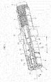
- FIG. 1 Details and advantages of the invention will become apparent from the following description of an embodiment FIG. 1 become clear.
- FIG. 1 shows a section of an electrical cable extending in the usual way in the cable longitudinal direction L between two free ends.
- the section shows the environment of a first free end E of the cable.
- the cable comprises at least one core, in the exemplary embodiment more precisely four wires 1.
- a respective core 1 is provided with an electrically insulating sheath 12; and the wires 1 of the cable are surrounded by a cable sheath 2.
- the cable is assembled in the region of the free end E such that an electrical connector for contacting a mating connector is formed.
- the wires 1 are stripped in the region of the free end E, that is freed from the insulating sheath 12, and provided with an electrical contact element 11, which - as a different from the core 1, separate component - is electrically connected to the wire 1 , eg by crimping.
- the contact element 11 of a respective core 1 is received in an electrically insulating, for example made of plastic, carrier 4.
- a subsequent to the free end E of the cable first portion 11a of the contact element 11 of a respective wire 1 serves as an electrical contact, while in the axial direction, that is, in the cable longitudinal direction L, adjoining second portion 11b of the contact element 11 in contrast no electrical contact to produce with another electrical element.
- the electrically insulating support 4 is provided with openings 40 (in its jacket surrounding the wires 1), through which the contact element 11 of a respective core 1 in the radial direction R, that is perpendicular to the cable longitudinal direction L, is accessible from the outside. This allows for an electrical contacting of a respective core 1 on the first section 11a of the respective contact element 11th
- the wires 1 with their respective contact element 11 can be inserted through a respective aperture 40 in the radial direction R into the carrier 4. Specifically, the wires 1 with their respective contact element 11 are radially clipped into the carrier 4. For this purpose, the latter has latching projections 42 which project into a respective opening 40.
- a receptacle 41 is formed in the support 4 for the electrical contact element 11 of a respective core 1 of the cable, in which the respective contact element 11 is latchingly received and is simultaneously accessible in the radial direction R.
- At the respective contact element 11 of the wires 1 in cable longitudinal direction L includes a screen 3 in the form of a braided shield, which surrounds the wires 1 including the respective insulating sheath 12.
- an outer conductor sleeve 5 is pushed, which rests on the one hand on the screen 3 and on the other hand - together with an outer terminal portion 6 - the electrically insulating support 4 encloses, wherein the connection portion 6 openings are provided which the radial Ensure accessibility of the first section 11a of the contact element 11 of a respective core 1.
- the outer conductor sleeve 5 is connected to the electrically insulating support 4 at an attachment point 55 by crimping (crimp connection).
- this portion 11 b of a respective contact element 11 according to the invention is electrically isolated on its outer surface.
- the electrical insulation of a respective second portion 11b on the contact element 11 of a wire 1 is advantageously made after the introduction of the contact element 11 of the corresponding wire 1 in the carrier 4 (but before pushing the outer conductor sleeve 5).
- the isolation of a respective second subsection 11b can thus take place selectively at those points which are accessible from the outside through the respectively associated opening 40 in the carrier 4.
- the insulation of a respective second subsection 11b on the contact element 11 of a wire 1 by applying an insulating coating through the respective associated opening 40 of the carrier 4 is carried out.
- the coating can be carried out, for example, by applying an insulating varnish to the second subsection 11b.
- Suitable paints can be e.g. in a simple manner on the respective section 11b spray.
- short processing times can be achieved by accelerating the drying of the varnish by UV irradiation.
- the general purpose is to apply an insulating layer (separating layer) to the second subsection 11b of the contact element 11 of a respective core 1, or to otherwise insulate the surface of a respective subsection 11b.
- an insulating layer separating layer
- a passivation of the outer surface of a respective second portion 11 b may be provided on the contact element 11 of the wires 1, for example by electroplating the corresponding surface (using tin).
- paint for insulating coating of the second portion 11b on the contact element 11 of a respective core 1 is connected to the insulation only a very small amount of material; This is therefore almost neutral in weight.
- a lacquer layer of a few micrometers is sufficient to ensure sufficient insulation of the second section 11b on a respective core 1.
Landscapes
- Engineering & Computer Science (AREA)
- Manufacturing & Machinery (AREA)
- Details Of Connecting Devices For Male And Female Coupling (AREA)
- Insulated Conductors (AREA)
- Manufacturing Of Electrical Connectors (AREA)
- Connections Effected By Soldering, Adhesion, Or Permanent Deformation (AREA)
Description
- Die Erfindung betrifft ein konfektioniertes elektrisches Kabel nach dem Oberbegriff des Anspruchs 1 sowie ein Verfahren zur Herstellung eines solchen Kabels gemäß Anspruch 14.
- Ein konfektioniertes elektrisches Kabel der genannten Art umfasst mindestens eine Ader, insbesondere mehrere Adern, wobei eine jeweilige Ader eine elektrisch isolierende Hülle aufweist und sich in Kabellängsrichtung zwischen einem ersten und einem zweiten freien Ende des Kabels erstreckt sowie zumindest an einem Endabschnitt des Kabels zur Bildung eines elektrischen Kontaktes von der isolierenden Hülle befreit und mit einem elektrischen Kontaktelement - als einem von der Ader verschiedenen Bauelement - versehen (d.h., elektrisch leitend verbunden) ist, z.B. durch Crimpen. Eine jeweilige Ader des Kabels ist in einem elektrisch isolierenden Träger aufgenommen, und zwar jeweils mit ihrem von der isolierenden Hülle befreiten (abisolierten) und mit einem elektrischen Kontaktelement versehenen Bereich. Jener Träger ist hierfür mit mindestens einem Durchbruch versehen, durch den hindurch das Kontaktelement einer (jeweiligen) Ader von außen zugänglich ist, um einen elektrischen Kontakt mit einem Gegenstecker herstellen zu können.
- Ein derartiges konfektioniertes elektrisches Kabel ist beispielsweise aus der
US 2003/0199205 A1 bekannt. - Bei der Herstellung jenes konfektionierten Kabels besteht das Problem, dass ein Teil des abisolierten Bereiches einer Ader, insbesondere das dortige Kontaktelement, zum Beispiel beim Aufschieben einer Außenleiterhülse an einem freien Ende des Kabels, in unerwünschten elektrischen Kontakt mit einem weiteren elektrisch leitfähigen Element, wie beispielsweise einem Drahtrest eines am Kabel vorgesehenen Schirmgeflechtes, geraten könnte.
- Der Erfindung liegt das Problem zugrunde, ein konfektioniertes elektrisches Kabel der eingangs genannten Art zu verbessern und insbesondere den vorstehend genannten Nachteil zu vermeiden.
- Dieses Problem wird erfindungsgemäß durch die Schaffung eines konfektionierten elektrischen Kabels mit den Merkmalen des Anspruchs 1 gelöst.
- Danach ist der durch den mindestens Durchbruch des isolierenden Trägers hindurch zugängliche, mit einem elektrischen Kontaktelement versehene Bereich einer jeweiligen Ader in einem Teilabschnitt, und zwar in einem nicht als elektrischer Kontakt (zur Kontaktierung eines Gegensteckers) dienenden Teilabschnitt, mit einer von der isolierenden Hülle der Ader verschiedenen elektrischen Isolierung versehen, wobei auf jenen Teilabschnitt des Kontaktelementes als elektrische Isolierung eine isolierende Beschichtung aufgebracht ist, und zwar durch Aufbringen einer isolierenden Beschichtung durch den jeweils zugeordneten Durchbruch des Trägers hindurch, was nach dem Einbringen des Kontaktelementes der entsprechenden Ader in den Träger vorgenommen wurde. Hierbei kann es sich beispielsweise um eine Lackschicht oder um eine Passivierungsschicht handeln.
- Die erfindungsgemäße Lösung ermöglicht mit einfachen, kostengünstigen und nahezu gewichtsneutralen Mitteln einen Schutz eines Teilabschnittes des Kontaktelementes einer jeweiligen Ader, welcher nicht als elektrischer Kontakt dienen soll, vor der unbeabsichtigten elektrischen Kontaktierung mit einem elektrisch leitfähigen Fremdkörper. Hierdurch muss ein solcher Teilabschnitt des Kontaktelementes einer jeweiligen Ader nicht vollständig von dem Material des zugehörigen Trägers umgeben sein, was einerseits Gewicht spart und andererseits zusätzliche Möglichkeiten bei der Konfektionierung des Kabels öffnet.
- Erfindungsgemäß kann vorgesehen sein, dass das Kontaktelement einer jeweiligen Ader zur Herstellung eines elektrischen Kontaktes mit einem Gegenstecker in radialer Richtung bezüglich der Kabellängsrichtung (also senkrecht zur Kabellängsrichtung) durch den Durchbruch des zugehörigen Trägers hindurch zugänglich ist. Ein solcher Durchbruch kann zugleich dazu genutzt werden, um das Kontaktelement einer jeweiligen Ader in radialer Richtung in den isolierenden Träger einzuführen, insbesondere dort radial einzuclipsen. Hierzu kann an dem Träger mindestens ein über den Durchbruch ragender Rastvorsprung ausgebildet sein. Der nicht der elektrischen Kontaktierung mit einem Gegenstecker dienende, im zugehörigen Träger aufgenommene Teilabschnitt des Kontaktelementes wird an seiner äußeren Oberfläche isoliert, um unerwünschten elektrischen Kontakt in diesem Teilabschnitt zu vermeiden.
- Die elektrische Isolation jenes Teilabschnittes eines jeweiligen Kontaktelementes kann dabei insbesondere gezielt nach dem Einbringen des jeweiligen Kontaktelementes in den elektrisch isolierenden Träger durch dessen mindestens einen Durchbruch hindurch vorgenommen werden. Dies ermöglicht eine Isolierung gezielt solcher Teile des Kontaktelementes einer Ader, die durch einen Durchbruch des Trägers hindurch zugänglich sind (die jedoch nicht als elektrischer Kontakt dienen sollen). Dabei bleiben solche Stellen des Kontaktelementes frei von der zusätzlichen Isolierung, die an dem Träger anliegen.
- Zwar ist aus der
DE 41 19 202 A1 bereits ein elektrischer Steckverbinder bekannt, bei dem Kontaktelemente mit einem isolierenden Material beschichtet sind, um diese gegenüber einem metallischen Gehäuseblock zu isolieren. Dies hat jedoch nichts mit dem vorstehend zu lösenden Problem zu tun, wo es ja um die Aufnahme abisolierter Enden der Adern eines elektrischen Kabels in einem elektrisch isolierenden Träger geht. - Ein Verfahren zur Herstellung eines erfindungsgemäßen konfektionierten elektrischen Kabels ist durch die Merkmale des Anspruchs 14 charakterisiert.
- Vorteilhafte Weiterbildungen des Verfahrens ergeben sich aus den hiervon abhängigen Ansprüchen.
- Weitere Einzelheiten und Vorteile der Erfindung werden bei der nachfolgenden Beschreibung eines Ausführungsbeispieles anhand
Figur 1 deutlich werden. -
Figur 1 zeigt einen Ausschnitt eines elektrischen Kabels, das sich in üblicher Weise in Kabellängsrichtung L zwischen zwei freien Enden erstreckt. Der Ausschnitt zeigt dabei die Umgebung eines ersten freien Endes E des Kabels. Das Kabel umfasst mindestens eine Ader, im Ausführungsbeispiel genauer vier Adern 1. Eine jeweilige Ader 1 ist dabei mit einer elektrisch isolierenden Hülle 12 versehen; und die Adern 1 des Kabels sind von einem Kabelmantel 2 umgeben. - Das Kabel ist im Bereich des freien Endes E derart konfektioniert, dass ein elektrischer Steckverbinder zur Kontaktierung eines Gegensteckers gebildet wird. Hierzu sind die Adern 1 im Bereich des freien Endes E abisoliert, also von der isolierenden Hülle 12 befreit, und mit einem elektrischen Kontaktelement 11 versehen, welches - als ein von der Ader 1 verschiedenes, separates Bauelement - mit der Ader 1 elektrisch leitend verbunden ist, z.B. durch Crimpen. Das Kontaktelement 11 einer jeweiligen Ader 1 ist in einem elektrisch isolierenden, zum Beispiel aus Kunststoff bestehenden, Träger 4 aufgenommen. Dabei dient ein an das freie Ende E des Kabels anschließender erster Teilabschnitt 11a des Kontaktelementes 11 einer jeweiligen Ader 1 als elektrischer Kontakt, während ein in axialer Richtung, das heißt, in Kabellängsrichtung L, daran anschließender zweiter Teilabschnitt 11b des Kontaktelementes 11 demgegenüber keinen elektrischen Kontakt mit einem weiteren elektrischen Element herstellen soll.
- Der elektrisch isolierende Träger 4 ist mit Durchbrüchen 40 (in seinem die Adern 1 umgebenden Mantel) versehen, durch die hindurch das Kontaktelement 11 einer jeweiligen Ader 1 in radialer Richtung R, also senkrecht zur Kabellängsrichtung L, von außen zugänglich ist. Dies ermöglicht zum einen eine elektrische Kontaktierung einer jeweiligen Ader 1 am ersten Teilabschnitt 11a des jeweiligen Kontaktelementes 11.
- Zum anderen können die Adern 1 mit ihrem jeweiligen Kontaktelement 11 durch einen jeweiligen Durchbruch 40 hindurch in radialer Richtung R in den Träger 4 eingesetzt werden. Konkret sind die Adern 1 mit ihrem jeweiligen Kontaktelement 11 radial in den Träger 4 einclipsbar. Hierzu weist letzterer Rastvorsprünge 42 auf, die in einen jeweiligen Durchbruch 40 hineinragen.
- Im Ergebnis wird in dem Träger 4 für das elektrische Kontaktelement 11 einer jeweiligen Ader 1 des Kabels jeweils eine Aufnahme 41 gebildet, in welcher das jeweilige Kontaktelement 11 rastend aufgenommen ist und gleichzeitig in radialer Richtung R zugänglich ist.
- An das jeweilige Kontaktelement 11 der Adern 1 schließt in Kabellängsrichtung L ein Schirm 3 in Form eines Schirmgeflechtes an, welcher die Adern 1 einschließlich der jeweiligen isolierenden Hülle 12 umgibt.
- Auf das Kabel ist im Bereich des Endes E weiterhin eine Außenleiterhülse 5 aufgeschoben, welche einerseits an dem Schirm 3 anliegt und andererseits - zusammen mit einem äußeren Anschlussabschnitt 6 - den elektrisch isolierenden Träger 4 umschließt, wobei im Anschlussabschnitt 6 Öffnungen vorgesehen sind, welche die radiale Zugänglichkeit des ersten Teilabschnittes 11a des Kontaktelementes 11 einer jeweiligen Ader 1 gewährleisten. Die Außenleiterhülse 5 ist mit dem elektrisch isolierenden Träger 4 an einer Befestigungsstelle 55 durch Crimpen verbunden (Crimp-Verbindung).
- Bei einer derartigen Anordnung besteht das Problem, dass beim Aufschieben der Außenleiterhülse 5 auf den elektrisch isolierenden Träger 4 in axialer Richtung (d.h., in Kabellängsrichtung L) ein elektrischer Kontakt (Kurzschluss) zwischen dem Kontaktelement 11 einer jeweiligen Ader 1 und dem Kabelschirm 3 zuverlässig vermieden werden soll. Ein ungewollter elektrischer Kontakt könnte beispielsweise dadurch herbeigeführt werden, dass ein Draht des den Kabelschirm 3 bildenden Schirmgeflechtes beim Aufschieben der Außenleiterhülse 5 mitgenommen und dabei gegen das Kontaktelement 11 einer Ader 1 gedrückt wird, und zwar durch den zugehörigen Durchbruch 40 hindurch. Dies betrifft insbesondere den benachbart zu dem Kabelschirm 3 liegenden zweiten Teilabschnitt 11b des Kontaktelementes 11 einer jeweiligen Ader 1. Da ein solcher Teilabschnitt 11b nicht der Kontaktierung mit einem Gegenstecker dient, sondern vielmehr vor allem deshalb abisoliert ist, um das radiale Einführen in den Träger 4 zu ermöglichen, wird dieser Teilabschnitt 11b eines jeweiligen Kontaktelementes 11 erfindungsgemäß an seiner äußeren Oberfläche elektrisch isoliert.
- Die elektrische Isolierung eines jeweiligen zweiten Teilabschnittes 11b am Kontaktelement 11 einer Ader 1 wird vorliegend vorteilhaft nach dem Einbringen des Kontaktelementes 11 der entsprechenden Ader 1 in den Träger 4 (jedoch vor dem Aufschieben der Außenleiterhülse 5) vorgenommen. Die Isolierung eines jeweiligen zweiten Teilabschnittes 11b kann somit gezielt an denjenigen Stellen erfolgen, welche durch den jeweils zugehörigen Durchbruch 40 im Träger 4 hindurch von außen zugänglich sind.
- Gemäß einer Variante erfolgt die Isolierung eines jeweiligen zweiten Teilabschnittes 11b am Kontaktelement 11 einer Ader 1 durch Aufbringen einer isolierenden Beschichtung durch den jeweils zugeordneten Durchbruch 40 des Trägers 4 hindurch. Die Beschichtung kann beispielsweise durch Aufbringen eines isolierenden Lackels auf den zweiten Teilabschnitt 11b vorgenommen werden. Geeignete Lacke lassen sich z.B. in einfacher Weise auf den jeweiligen Teilabschnitt 11b aufsprühen. Bei Verwendung eines UVhärtbaren Lackes zur Bildung einer isolierenden Schicht lassen sich zudem kurze Bearbeitungszeiten erreichen, indem das Trocknen des Lackes durch UV-Bestrahlung beschleunigt wird.
- Bei einem nachträglichen Aufbringen der Isolierung auf den zweiten Teilabschnitt 11b des Kontaktelementes 11 bleiben solche Bereiche jenes Teilabschnittes, die (hinreichend dicht) am isolierenden Träger 4 anliegen, frei von der zusätzlichen Isolierung.
- Allgemein geht es darum, auf den zweiten Teilabschnitt 11b des Kontaktelementes 11 einer jeweiligen Ader 1 ein isolierenden Schicht (Trennschicht) aufzubringen oder die Oberfläche eines jeweiligen Teilabschnitts 11b in sonstiger Weise zu isolieren. Hierfür kommen neben dem bereits dargestellten Lackieren noch weitere Möglichkeiten in Betracht.
- So kann eine Passivierung der äußeren Oberfläche eines jeweiligen zweiten Teilabschnittes 11b am Kontaktelement 11 der Adern 1 vorgesehen sein, zum Beispiel durch Galvanisieren der entsprechenden Oberfläche (unter Verwendung von Zinn). Insbesondere bei der Verwendung von Lack zur isolierenden Beschichtung des zweiten Teilabschnittes 11b am Kontaktelement 11 einer jeweiligen Ader 1 ist mit der Isolierung nur ein sehr geringer Materialaufwand verbunden; diese ist also nahezu gewichtsneutral. Bei typischen Spannungen von 12 V, die am konfektionierten Kabel anliegen, genügt eine Lackschicht von wenigen Mikrometern, um eine hinreichende Isolierung des zweiten Teilabschnittes 11b an einer jeweiligen Ader 1 sicherzustellen.
Claims (15)
- Konfektioniertes elektrisches Kabel mit- mindestens einer von einer isolierenden Hülle (12) umgebenen Ader (1), die sich in Kabellängsrichtung (L) zwischen einem ersten und einem zweiten freien Ende des Kabels erstreckt und die am ersten freien Ende (E) des Kabels von der isolierenden Hülle (12) befreit und mit einem elektrischen Kontaktelement (11) versehen ist, und- einem elektrisch isolierenden Träger (4), in dem die mindestens eine Ader (1) mit ihrem Kontaktelement (11) aufgenommen ist,wobei der Träger (4) mit mindestens einem Durchbruch (40) versehen ist, durch den hindurch das Kontaktelement (11) von außen zugänglich ist,
dadurch gekennzeichnet,
dass das durch den mindestens einen Durchbruch (40) hindurch zugängliche Kontaktelement (11) in einem Teilabschnitt (11b) mit einer von der isolierenden Hülle (12) verschiedenen elektrischen Isolierung in Form einer isolierenden Beschichtung versehen ist, durch Aufbringen der isolierenden Beschichtung durch den mindestens einen Durchbruch (40) des Trägers (4)
hindurch nach dem Einbringen des Kontaktelementes (11) der entsprechenden Ader (1) in den Träger (4). - Elektrisches Kabel nach Anspruch 1, dadurch gekennzeichnet, dass das Kontaktelement (11) in radialer Richtung (R) - bezogen auf die Kabellängsrichtung (L) - durch den Durchbruch (40) des Trägers (4) hindurch zugänglich ist.
- Elektrisches Kabel nach Anspruch 2, dadurch gekennzeichnet, dass das Kontaktelement (11) in radialer Richtung (R) durch den Durchbruch (40) hindurch in den Träger (4) einführbar ist.
- Elektrisches Kabel nach Anspruch 3, dadurch gekennzeichnet, dass das Kontaktelement (11) in den Träger (4) einrastbar ist.
- Elektrisches Kabel nach Anspruch 4, dadurch gekennzeichnet, dass zum Verrasten des Kontaktelementes (11) in dem Träger (4) mindestens ein Rastvorsprung (42) in den Durchbruch (40) hineinragt.
- Elektrisches Kabel nach einem der vorhergehenden Ansprüche, dadurch gekennzeichnet, dass das Kontaktelement (11) durch Crimpen mit der zugehörigen Ader (1) verbunden ist.
- Elektrisches Kabel nach einem der vorhergehenden Ansprüche, dadurch gekennzeichnet, dass die elektrische Isolierung nach dem Einfügen des Kontaktelements (11) in den Träger (4) auf den einen Teilabschnitt (11b) des Kontaktelementes (11) aufgebracht worden ist.
- Elektrisches Kabel nach einem der vorhergehenden Ansprüche, dadurch gekennzeichnet, dass das Kontaktelement (11) an Stellen des einen Teilabschnittes (11b), an denen es am Träger (4) anliegt, keine elektrische Isolierung aufweist.
- Elektrisches Kabel nach einem der vorhergehenden Ansprüche, dadurch gekennzeichnet, dass das Kontaktelement (11) in einem ersten Teilabschnitt (11a), welcher benachbart zu dem freien Ende (E) des Kabels angeordnet ist, als elektrischer Kontakt zur Kontaktierung eines Gegensteckers ausgebildet ist und in einem entlang der Kabellängsrichtung (L) daran anschließenden zweiten Teilabschnitt als dem einen Teilabschnitt (11b) mit der elektrischen Isolierung versehen ist.
- Elektrisches Kabel nach einem der vorhergehenden Ansprüche, dadurch gekennzeichnet, dass an dem sich an das freie Ende (E) anschließenden Endabschnitt des Kabels ein Kabelschirm (3) angeordnet ist, insbesondere in Form eines Schirmgeflechtes, der die mindestens eine Ader (1) außerhalb ihres Kontaktelementes (11) umgibt.
- Elektrisches Kabel nach einem der vorhergehenden Ansprüche, dadurch gekennzeichnet, dass der Kabelschirm (3) und der isolierende Träger (4) von einem elektrischen Außenleiter (5) umgriffen sind.
- Elektrisches Kabel nach Anspruch 11, dadurch gekennzeichnet, dass die isolierende Beschichtung als eine Lackschicht ausgeführt ist.
- Elektrisches Kabel nach Anspruch 11, dadurch gekennzeichnet, dass die isolierende Beschichtung als eine Passivierungsschicht ausgeführt ist.
- Verfahren zum Herstellen eines konfektionierten elektrischen Kabels, das mindestens eine von einer isolierenden Hülle (12) umgebene Ader (1) aufweist, die sich in Kabellängsrichtung (L) zwischen einem ersten und einem zweiten freien Ende des Kabels erstreckt und die am ersten freien Ende (E) des Kabels von der isolierenden Hülle (12) befreit ist, wobei die mindestens eine Ader (1) an ihrem von der isolierenden Hülle (12) befreiten, abisolierten Bereich mit einem elektrischen Kontaktelement (11) versehen wird und mit dem Kontaktelement (11) in einem elektrisch isolierenden Träger (4) angeordnet wird, der mit mindestens einem Durchbruch (40) versehen ist, durch den hindurch das Kontaktelement (11) von außen zugänglich ist,
dadurch gekennzeichnet,
dass ein Teilabschnitt (11b) des Kontaktelementes (11) durch den mindestens einen Durchbruch (40) des Trägers (4) hindurch mit einer Isolierung in Form einer isolierenden Beschichtung
versehen wird, durch Aufbringen der isolierenden Beschichtung durch den mindestens einen Durchbruch (40) des Trägers (4) hindurch nachdem das Kontaktelement (11) der entsprechenden Ader (1) in dem Träger (4) angeordnet worden ist. - Verfahren nach Anspruch 14, mit dem ein konfektioniertes elektrisches Kabel nach einem der Ansprüche 2 bis 13 hergestellt wird.
Priority Applications (6)
| Application Number | Priority Date | Filing Date | Title |
|---|---|---|---|
| EP15185351.2A EP3145033B1 (de) | 2015-09-15 | 2015-09-15 | Konfektioniertes elektrisches kabel |
| HUE15185351A HUE048033T2 (hu) | 2015-09-15 | 2015-09-15 | Használatra kész villamos kábel |
| DE102016213151.6A DE102016213151A1 (de) | 2015-09-15 | 2016-07-19 | Konfektioniertes elektrisches Kabel |
| MX2016010060A MX361578B (es) | 2015-09-15 | 2016-08-03 | Cable eléctrico confeccionado. |
| CN201610812413.9A CN107039816B (zh) | 2015-09-15 | 2016-09-09 | 集束的电缆和用于制造集束的电缆的方法 |
| US15/264,614 US9929518B2 (en) | 2015-09-15 | 2016-09-14 | Assembled electrical cable |
Applications Claiming Priority (1)
| Application Number | Priority Date | Filing Date | Title |
|---|---|---|---|
| EP15185351.2A EP3145033B1 (de) | 2015-09-15 | 2015-09-15 | Konfektioniertes elektrisches kabel |
Publications (2)
| Publication Number | Publication Date |
|---|---|
| EP3145033A1 EP3145033A1 (de) | 2017-03-22 |
| EP3145033B1 true EP3145033B1 (de) | 2019-12-04 |
Family
ID=54145700
Family Applications (1)
| Application Number | Title | Priority Date | Filing Date |
|---|---|---|---|
| EP15185351.2A Active EP3145033B1 (de) | 2015-09-15 | 2015-09-15 | Konfektioniertes elektrisches kabel |
Country Status (6)
| Country | Link |
|---|---|
| US (1) | US9929518B2 (de) |
| EP (1) | EP3145033B1 (de) |
| CN (1) | CN107039816B (de) |
| DE (1) | DE102016213151A1 (de) |
| HU (1) | HUE048033T2 (de) |
| MX (1) | MX361578B (de) |
Families Citing this family (4)
| Publication number | Priority date | Publication date | Assignee | Title |
|---|---|---|---|---|
| EP3467960B1 (de) * | 2017-10-09 | 2022-03-09 | MD Elektronik GmbH | Elektrischer steckverbinder |
| DE102017009370A1 (de) * | 2017-10-10 | 2019-04-11 | Rosenberger Hochfrequenztechnik Gmbh & Co. Kg | Steckverbinderanordnung |
| CN113224558B (zh) * | 2021-05-06 | 2023-04-11 | 江苏正恺电子科技有限公司 | 一种多通道配接大直径低衰减电缆的连接器 |
| US20230007971A1 (en) * | 2021-07-08 | 2023-01-12 | Heartware, Inc. | Dual stator pump split connnector |
Family Cites Families (11)
| Publication number | Priority date | Publication date | Assignee | Title |
|---|---|---|---|---|
| FR2663163B1 (fr) | 1990-06-11 | 1993-12-10 | Amp Inc | Assemblage de connecteur electrique. |
| DE20203788U1 (de) * | 2002-03-08 | 2002-06-06 | Anton Hummel Verwaltungs Gmbh, 79183 Waldkirch | Steckverbinder mit einem Gehäuse und mit einem Klemmeinsatz |
| US6764350B2 (en) | 2002-04-23 | 2004-07-20 | Itt Manufacturing Enterprises, Inc. | Connector contact retention |
| US7044789B2 (en) * | 2004-08-13 | 2006-05-16 | Tyco Electronics Corporation | Electrical connector |
| DE102009010492B3 (de) | 2009-02-25 | 2010-05-27 | Harting Electric Gmbh & Co. Kg | Kabelordnender Einsatz für Steckverbinder |
| DE202010009766U1 (de) * | 2010-07-02 | 2010-09-16 | Rosenberger Hochfrequenztechnik Gmbh & Co. Kg | Drehbarer Steckverbinder |
| JP5622314B2 (ja) * | 2010-10-12 | 2014-11-12 | 矢崎総業株式会社 | コネクタ端子の電線接続構造 |
| US8911254B2 (en) * | 2011-06-03 | 2014-12-16 | Ppc Broadband, Inc. | Multi-conductor cable connector having more than one coaxial cable and method thereof |
| HUE050214T2 (hu) * | 2012-02-16 | 2020-11-30 | Md Elektronik Gmbh | Kábel jelek átvitelére |
| JP5766644B2 (ja) * | 2012-03-26 | 2015-08-19 | 株式会社フジクラ | 編組シールド電線の接続構造及びシールドワイヤハーネスの製造方法 |
| DE102012103708B3 (de) * | 2012-04-27 | 2013-07-11 | HARTING Electronics GmbH | Isolierkörper eines Steckverbinder |
-
2015
- 2015-09-15 HU HUE15185351A patent/HUE048033T2/hu unknown
- 2015-09-15 EP EP15185351.2A patent/EP3145033B1/de active Active
-
2016
- 2016-07-19 DE DE102016213151.6A patent/DE102016213151A1/de not_active Withdrawn
- 2016-08-03 MX MX2016010060A patent/MX361578B/es active IP Right Grant
- 2016-09-09 CN CN201610812413.9A patent/CN107039816B/zh active Active
- 2016-09-14 US US15/264,614 patent/US9929518B2/en not_active Expired - Fee Related
Non-Patent Citations (1)
| Title |
|---|
| None * |
Also Published As
| Publication number | Publication date |
|---|---|
| CN107039816B (zh) | 2020-02-14 |
| MX2016010060A (es) | 2017-04-27 |
| MX361578B (es) | 2018-12-11 |
| HUE048033T2 (hu) | 2020-05-28 |
| US9929518B2 (en) | 2018-03-27 |
| US20170077658A1 (en) | 2017-03-16 |
| CN107039816A (zh) | 2017-08-11 |
| EP3145033A1 (de) | 2017-03-22 |
| DE102016213151A1 (de) | 2017-03-16 |
Similar Documents
| Publication | Publication Date | Title |
|---|---|---|
| EP3251180B1 (de) | Steckverbinderanordnung mit kompensationshülse | |
| DE19634065B4 (de) | Spleißvorrichtung und Verfahren zur Herstellung einer Spleißstelle für abgeschirmte Kabel | |
| DE102019106980B3 (de) | Kontaktträger und Steckverbinder für eine geschirmte hybride Kontaktanordnung | |
| DE202013006297U1 (de) | Steckverbinder | |
| EP3685471B1 (de) | Hochstromsteckverbinder mit isolierhülse | |
| EP3767750B1 (de) | Elektrischer steckverbinder, isolierschutzelement und verfahren zur montage eines elektrischen steckverbinders | |
| EP3327868B1 (de) | Elektrischer steckverbinder für ein mehradriges elektrisches kabel | |
| DE102017006767A1 (de) | Steckverbinderanordnung | |
| DE102017217079A1 (de) | Elektrischer Steckverbinder für ein mehradriges elektrisches Kabel | |
| EP3145033A1 (de) | Konfektioniertes elektrisches kabel | |
| EP2345110B1 (de) | Steckverbinder für ein sternvierer-kabel | |
| EP3467960B1 (de) | Elektrischer steckverbinder | |
| EP1683235A1 (de) | Koaxialkabel und verfahren zu dessen herstellung | |
| DE102013016099A1 (de) | Mehrfachanschlusskabel zur Verbindung von Hochspannungsvorrichtungen eines Kraftfahrzeugs und Kraftfahrzeug | |
| DE102017220944A1 (de) | Elektrischer Steckverbinder für ein mehradriges elektrisches Kabel | |
| DE102023209887B4 (de) | Kontaktanbindung für eine elektrische Leitung | |
| EP3465841B1 (de) | Koaxialsteckverbinder | |
| DE102021100858B4 (de) | Crimpverbinder zum Anschluss eines einen Kabelschirm aufweisenden Kabels an eine elektronische Baugruppe | |
| EP4246738B1 (de) | Rundsteckverbinder, verwendung eines rundsteckverbinders sowie verfahren zur herstellung eines rundsteckverbinders | |
| EP3830910A1 (de) | Steckvorrichtung mit verrastbaren komponenten | |
| DE102017219134A1 (de) | Elektrischer Steckverbinder für ein mehradriges elektrisches Kabel | |
| DE202006000336U1 (de) | Steckverbinder mit vereinfachter Kabelführung | |
| DE102020110495A1 (de) | Stecker für Datenkabel | |
| DE102022125029A1 (de) | Hybrides Kontaktelement | |
| DE102020110672A1 (de) | Verbindungsanordnung eines Rundleiters mit einem Flachleiter sowie Verfahren |
Legal Events
| Date | Code | Title | Description |
|---|---|---|---|
| PUAI | Public reference made under article 153(3) epc to a published international application that has entered the european phase |
Free format text: ORIGINAL CODE: 0009012 |
|
| STAA | Information on the status of an ep patent application or granted ep patent |
Free format text: STATUS: THE APPLICATION HAS BEEN PUBLISHED |
|
| AK | Designated contracting states |
Kind code of ref document: A1 Designated state(s): AL AT BE BG CH CY CZ DE DK EE ES FI FR GB GR HR HU IE IS IT LI LT LU LV MC MK MT NL NO PL PT RO RS SE SI SK SM TR |
|
| AX | Request for extension of the european patent |
Extension state: BA ME |
|
| STAA | Information on the status of an ep patent application or granted ep patent |
Free format text: STATUS: REQUEST FOR EXAMINATION WAS MADE |
|
| 17P | Request for examination filed |
Effective date: 20170920 |
|
| RBV | Designated contracting states (corrected) |
Designated state(s): AL AT BE BG CH CY CZ DE DK EE ES FI FR GB GR HR HU IE IS IT LI LT LU LV MC MK MT NL NO PL PT RO RS SE SI SK SM TR |
|
| STAA | Information on the status of an ep patent application or granted ep patent |
Free format text: STATUS: EXAMINATION IS IN PROGRESS |
|
| 17Q | First examination report despatched |
Effective date: 20180628 |
|
| REG | Reference to a national code |
Ref country code: DE Ref legal event code: R079 Ref document number: 502015011112 Country of ref document: DE Free format text: PREVIOUS MAIN CLASS: H01R0009030000 Ipc: H01R0013658100 |
|
| RIC1 | Information provided on ipc code assigned before grant |
Ipc: H01R 9/03 20060101ALI20190719BHEP Ipc: H01R 13/03 20060101ALI20190719BHEP Ipc: H01R 13/436 20060101ALI20190719BHEP Ipc: H01R 24/20 20110101ALI20190719BHEP Ipc: H01R 43/20 20060101ALI20190719BHEP Ipc: H01R 13/6581 20110101AFI20190719BHEP Ipc: H01R 13/502 20060101ALI20190719BHEP Ipc: H01R 107/00 20060101ALI20190719BHEP |
|
| GRAP | Despatch of communication of intention to grant a patent |
Free format text: ORIGINAL CODE: EPIDOSNIGR1 |
|
| STAA | Information on the status of an ep patent application or granted ep patent |
Free format text: STATUS: GRANT OF PATENT IS INTENDED |
|
| INTG | Intention to grant announced |
Effective date: 20190911 |
|
| GRAS | Grant fee paid |
Free format text: ORIGINAL CODE: EPIDOSNIGR3 |
|
| GRAA | (expected) grant |
Free format text: ORIGINAL CODE: 0009210 |
|
| STAA | Information on the status of an ep patent application or granted ep patent |
Free format text: STATUS: THE PATENT HAS BEEN GRANTED |
|
| AK | Designated contracting states |
Kind code of ref document: B1 Designated state(s): AL AT BE BG CH CY CZ DE DK EE ES FI FR GB GR HR HU IE IS IT LI LT LU LV MC MK MT NL NO PL PT RO RS SE SI SK SM TR |
|
| REG | Reference to a national code |
Ref country code: GB Ref legal event code: FG4D Free format text: NOT ENGLISH |
|
| REG | Reference to a national code |
Ref country code: CH Ref legal event code: EP |
|
| REG | Reference to a national code |
Ref country code: AT Ref legal event code: REF Ref document number: 1210590 Country of ref document: AT Kind code of ref document: T Effective date: 20191215 |
|
| REG | Reference to a national code |
Ref country code: DE Ref legal event code: R096 Ref document number: 502015011112 Country of ref document: DE |
|
| REG | Reference to a national code |
Ref country code: IE Ref legal event code: FG4D Free format text: LANGUAGE OF EP DOCUMENT: GERMAN |
|
| REG | Reference to a national code |
Ref country code: NL Ref legal event code: MP Effective date: 20191204 |
|
| REG | Reference to a national code |
Ref country code: LT Ref legal event code: MG4D |
|
| PG25 | Lapsed in a contracting state [announced via postgrant information from national office to epo] |
Ref country code: SE Free format text: LAPSE BECAUSE OF FAILURE TO SUBMIT A TRANSLATION OF THE DESCRIPTION OR TO PAY THE FEE WITHIN THE PRESCRIBED TIME-LIMIT Effective date: 20191204 Ref country code: LT Free format text: LAPSE BECAUSE OF FAILURE TO SUBMIT A TRANSLATION OF THE DESCRIPTION OR TO PAY THE FEE WITHIN THE PRESCRIBED TIME-LIMIT Effective date: 20191204 Ref country code: NO Free format text: LAPSE BECAUSE OF FAILURE TO SUBMIT A TRANSLATION OF THE DESCRIPTION OR TO PAY THE FEE WITHIN THE PRESCRIBED TIME-LIMIT Effective date: 20200304 Ref country code: GR Free format text: LAPSE BECAUSE OF FAILURE TO SUBMIT A TRANSLATION OF THE DESCRIPTION OR TO PAY THE FEE WITHIN THE PRESCRIBED TIME-LIMIT Effective date: 20200305 Ref country code: LV Free format text: LAPSE BECAUSE OF FAILURE TO SUBMIT A TRANSLATION OF THE DESCRIPTION OR TO PAY THE FEE WITHIN THE PRESCRIBED TIME-LIMIT Effective date: 20191204 Ref country code: FI Free format text: LAPSE BECAUSE OF FAILURE TO SUBMIT A TRANSLATION OF THE DESCRIPTION OR TO PAY THE FEE WITHIN THE PRESCRIBED TIME-LIMIT Effective date: 20191204 |
|
| REG | Reference to a national code |
Ref country code: HU Ref legal event code: AG4A Ref document number: E048033 Country of ref document: HU |
|
| PG25 | Lapsed in a contracting state [announced via postgrant information from national office to epo] |
Ref country code: RS Free format text: LAPSE BECAUSE OF FAILURE TO SUBMIT A TRANSLATION OF THE DESCRIPTION OR TO PAY THE FEE WITHIN THE PRESCRIBED TIME-LIMIT Effective date: 20191204 Ref country code: HR Free format text: LAPSE BECAUSE OF FAILURE TO SUBMIT A TRANSLATION OF THE DESCRIPTION OR TO PAY THE FEE WITHIN THE PRESCRIBED TIME-LIMIT Effective date: 20191204 |
|
| PG25 | Lapsed in a contracting state [announced via postgrant information from national office to epo] |
Ref country code: AL Free format text: LAPSE BECAUSE OF FAILURE TO SUBMIT A TRANSLATION OF THE DESCRIPTION OR TO PAY THE FEE WITHIN THE PRESCRIBED TIME-LIMIT Effective date: 20191204 |
|
| PG25 | Lapsed in a contracting state [announced via postgrant information from national office to epo] |
Ref country code: RO Free format text: LAPSE BECAUSE OF FAILURE TO SUBMIT A TRANSLATION OF THE DESCRIPTION OR TO PAY THE FEE WITHIN THE PRESCRIBED TIME-LIMIT Effective date: 20191204 Ref country code: PT Free format text: LAPSE BECAUSE OF FAILURE TO SUBMIT A TRANSLATION OF THE DESCRIPTION OR TO PAY THE FEE WITHIN THE PRESCRIBED TIME-LIMIT Effective date: 20200429 Ref country code: EE Free format text: LAPSE BECAUSE OF FAILURE TO SUBMIT A TRANSLATION OF THE DESCRIPTION OR TO PAY THE FEE WITHIN THE PRESCRIBED TIME-LIMIT Effective date: 20191204 Ref country code: NL Free format text: LAPSE BECAUSE OF FAILURE TO SUBMIT A TRANSLATION OF THE DESCRIPTION OR TO PAY THE FEE WITHIN THE PRESCRIBED TIME-LIMIT Effective date: 20191204 Ref country code: ES Free format text: LAPSE BECAUSE OF FAILURE TO SUBMIT A TRANSLATION OF THE DESCRIPTION OR TO PAY THE FEE WITHIN THE PRESCRIBED TIME-LIMIT Effective date: 20191204 |
|
| PG25 | Lapsed in a contracting state [announced via postgrant information from national office to epo] |
Ref country code: SK Free format text: LAPSE BECAUSE OF FAILURE TO SUBMIT A TRANSLATION OF THE DESCRIPTION OR TO PAY THE FEE WITHIN THE PRESCRIBED TIME-LIMIT Effective date: 20191204 Ref country code: SM Free format text: LAPSE BECAUSE OF FAILURE TO SUBMIT A TRANSLATION OF THE DESCRIPTION OR TO PAY THE FEE WITHIN THE PRESCRIBED TIME-LIMIT Effective date: 20191204 Ref country code: IS Free format text: LAPSE BECAUSE OF FAILURE TO SUBMIT A TRANSLATION OF THE DESCRIPTION OR TO PAY THE FEE WITHIN THE PRESCRIBED TIME-LIMIT Effective date: 20200404 |
|
| REG | Reference to a national code |
Ref country code: DE Ref legal event code: R097 Ref document number: 502015011112 Country of ref document: DE |
|
| PLBE | No opposition filed within time limit |
Free format text: ORIGINAL CODE: 0009261 |
|
| STAA | Information on the status of an ep patent application or granted ep patent |
Free format text: STATUS: NO OPPOSITION FILED WITHIN TIME LIMIT |
|
| PG25 | Lapsed in a contracting state [announced via postgrant information from national office to epo] |
Ref country code: DK Free format text: LAPSE BECAUSE OF FAILURE TO SUBMIT A TRANSLATION OF THE DESCRIPTION OR TO PAY THE FEE WITHIN THE PRESCRIBED TIME-LIMIT Effective date: 20191204 |
|
| 26N | No opposition filed |
Effective date: 20200907 |
|
| PG25 | Lapsed in a contracting state [announced via postgrant information from national office to epo] |
Ref country code: PL Free format text: LAPSE BECAUSE OF FAILURE TO SUBMIT A TRANSLATION OF THE DESCRIPTION OR TO PAY THE FEE WITHIN THE PRESCRIBED TIME-LIMIT Effective date: 20191204 Ref country code: SI Free format text: LAPSE BECAUSE OF FAILURE TO SUBMIT A TRANSLATION OF THE DESCRIPTION OR TO PAY THE FEE WITHIN THE PRESCRIBED TIME-LIMIT Effective date: 20191204 |
|
| PG25 | Lapsed in a contracting state [announced via postgrant information from national office to epo] |
Ref country code: MC Free format text: LAPSE BECAUSE OF FAILURE TO SUBMIT A TRANSLATION OF THE DESCRIPTION OR TO PAY THE FEE WITHIN THE PRESCRIBED TIME-LIMIT Effective date: 20191204 |
|
| REG | Reference to a national code |
Ref country code: CH Ref legal event code: PL |
|
| REG | Reference to a national code |
Ref country code: BE Ref legal event code: MM Effective date: 20200930 |
|
| PG25 | Lapsed in a contracting state [announced via postgrant information from national office to epo] |
Ref country code: LU Free format text: LAPSE BECAUSE OF NON-PAYMENT OF DUE FEES Effective date: 20200915 |
|
| PG25 | Lapsed in a contracting state [announced via postgrant information from national office to epo] |
Ref country code: LI Free format text: LAPSE BECAUSE OF NON-PAYMENT OF DUE FEES Effective date: 20200930 Ref country code: IE Free format text: LAPSE BECAUSE OF NON-PAYMENT OF DUE FEES Effective date: 20200915 Ref country code: BE Free format text: LAPSE BECAUSE OF NON-PAYMENT OF DUE FEES Effective date: 20200930 Ref country code: CH Free format text: LAPSE BECAUSE OF NON-PAYMENT OF DUE FEES Effective date: 20200930 |
|
| REG | Reference to a national code |
Ref country code: AT Ref legal event code: MM01 Ref document number: 1210590 Country of ref document: AT Kind code of ref document: T Effective date: 20200915 |
|
| PG25 | Lapsed in a contracting state [announced via postgrant information from national office to epo] |
Ref country code: AT Free format text: LAPSE BECAUSE OF NON-PAYMENT OF DUE FEES Effective date: 20200915 |
|
| PG25 | Lapsed in a contracting state [announced via postgrant information from national office to epo] |
Ref country code: TR Free format text: LAPSE BECAUSE OF FAILURE TO SUBMIT A TRANSLATION OF THE DESCRIPTION OR TO PAY THE FEE WITHIN THE PRESCRIBED TIME-LIMIT Effective date: 20191204 Ref country code: MT Free format text: LAPSE BECAUSE OF FAILURE TO SUBMIT A TRANSLATION OF THE DESCRIPTION OR TO PAY THE FEE WITHIN THE PRESCRIBED TIME-LIMIT Effective date: 20191204 Ref country code: CY Free format text: LAPSE BECAUSE OF FAILURE TO SUBMIT A TRANSLATION OF THE DESCRIPTION OR TO PAY THE FEE WITHIN THE PRESCRIBED TIME-LIMIT Effective date: 20191204 |
|
| PG25 | Lapsed in a contracting state [announced via postgrant information from national office to epo] |
Ref country code: MK Free format text: LAPSE BECAUSE OF FAILURE TO SUBMIT A TRANSLATION OF THE DESCRIPTION OR TO PAY THE FEE WITHIN THE PRESCRIBED TIME-LIMIT Effective date: 20191204 |
|
| P01 | Opt-out of the competence of the unified patent court (upc) registered |
Free format text: CASE NUMBER: APP_40854/2024 Effective date: 20240710 |
|
| PGFP | Annual fee paid to national office [announced via postgrant information from national office to epo] |
Ref country code: GB Payment date: 20240920 Year of fee payment: 10 |
|
| PGFP | Annual fee paid to national office [announced via postgrant information from national office to epo] |
Ref country code: FR Payment date: 20240925 Year of fee payment: 10 |
|
| PGFP | Annual fee paid to national office [announced via postgrant information from national office to epo] |
Ref country code: HU Payment date: 20240920 Year of fee payment: 10 |
|
| PGFP | Annual fee paid to national office [announced via postgrant information from national office to epo] |
Ref country code: IT Payment date: 20240924 Year of fee payment: 10 |
|
| PGFP | Annual fee paid to national office [announced via postgrant information from national office to epo] |
Ref country code: DE Payment date: 20250919 Year of fee payment: 11 |
|
| PGFP | Annual fee paid to national office [announced via postgrant information from national office to epo] |
Ref country code: BG Payment date: 20250919 Year of fee payment: 11 |
|
| PGFP | Annual fee paid to national office [announced via postgrant information from national office to epo] |
Ref country code: CZ Payment date: 20250908 Year of fee payment: 11 |
|
| GBPC | Gb: european patent ceased through non-payment of renewal fee |
Effective date: 20250915 |
|
| PG25 | Lapsed in a contracting state [announced via postgrant information from national office to epo] |
Ref country code: HU Free format text: LAPSE BECAUSE OF NON-PAYMENT OF DUE FEES Effective date: 20250916 |
|
| PG25 | Lapsed in a contracting state [announced via postgrant information from national office to epo] |
Ref country code: GB Free format text: LAPSE BECAUSE OF NON-PAYMENT OF DUE FEES Effective date: 20250915 |
|
| PG25 | Lapsed in a contracting state [announced via postgrant information from national office to epo] |
Ref country code: IT Free format text: LAPSE BECAUSE OF NON-PAYMENT OF DUE FEES Effective date: 20250915 |
|
| PG25 | Lapsed in a contracting state [announced via postgrant information from national office to epo] |
Ref country code: FR Free format text: LAPSE BECAUSE OF NON-PAYMENT OF DUE FEES Effective date: 20250930 |