EP3145065A1 - Machines électriques - Google Patents
Machines électriques Download PDFInfo
- Publication number
- EP3145065A1 EP3145065A1 EP16181115.3A EP16181115A EP3145065A1 EP 3145065 A1 EP3145065 A1 EP 3145065A1 EP 16181115 A EP16181115 A EP 16181115A EP 3145065 A1 EP3145065 A1 EP 3145065A1
- Authority
- EP
- European Patent Office
- Prior art keywords
- permanent magnets
- electrical machine
- moveable
- winding
- moveable element
- Prior art date
- Legal status (The legal status is an assumption and is not a legal conclusion. Google has not performed a legal analysis and makes no representation as to the accuracy of the status listed.)
- Withdrawn
Links
Images


Classifications
-
- H—ELECTRICITY
- H02—GENERATION; CONVERSION OR DISTRIBUTION OF ELECTRIC POWER
- H02K—DYNAMO-ELECTRIC MACHINES
- H02K16/00—Machines with more than one rotor or stator
- H02K16/02—Machines with one stator and two or more rotors
-
- H—ELECTRICITY
- H02—GENERATION; CONVERSION OR DISTRIBUTION OF ELECTRIC POWER
- H02K—DYNAMO-ELECTRIC MACHINES
- H02K7/00—Arrangements for handling mechanical energy structurally associated with dynamo-electric machines, e.g. structural association with mechanical driving motors or auxiliary dynamo-electric machines
- H02K7/10—Structural association with clutches, brakes, gears, pulleys or mechanical starters
- H02K7/11—Structural association with clutches, brakes, gears, pulleys or mechanical starters with dynamo-electric clutches
-
- H—ELECTRICITY
- H02—GENERATION; CONVERSION OR DISTRIBUTION OF ELECTRIC POWER
- H02K—DYNAMO-ELECTRIC MACHINES
- H02K21/00—Synchronous motors having permanent magnets; Synchronous generators having permanent magnets
- H02K21/12—Synchronous motors having permanent magnets; Synchronous generators having permanent magnets with stationary armatures and rotating magnets
- H02K21/14—Synchronous motors having permanent magnets; Synchronous generators having permanent magnets with stationary armatures and rotating magnets with magnets rotating within the armatures
- H02K21/16—Synchronous motors having permanent magnets; Synchronous generators having permanent magnets with stationary armatures and rotating magnets with magnets rotating within the armatures having annular armature cores with salient poles
-
- H—ELECTRICITY
- H02—GENERATION; CONVERSION OR DISTRIBUTION OF ELECTRIC POWER
- H02K—DYNAMO-ELECTRIC MACHINES
- H02K21/00—Synchronous motors having permanent magnets; Synchronous generators having permanent magnets
- H02K21/12—Synchronous motors having permanent magnets; Synchronous generators having permanent magnets with stationary armatures and rotating magnets
- H02K21/22—Synchronous motors having permanent magnets; Synchronous generators having permanent magnets with stationary armatures and rotating magnets with magnets rotating around the armatures, e.g. flywheel magnetos
Definitions
- the present invention relates to electrical machines
- Mechanical gearboxes are extensively used to match the operating speed of prime-movers to the requirements of their loads for both increasing the rotational speed such as, for example, in a wind-powered generators or reducing rotational speed such as, for example, in an electric-ship propulsion arrangement. It is usually more cost and weight effective to employ a high-speed electrical machine in conjunction with a mechanical gearbox to achieve requisite speed and torque characteristics.
- a high-speed electrical machine in conjunction with a mechanical gearbox allows high system torque densities to be realised, such mechanical gearboxes usually require lubrication and cooling.
- reliability can also be a significant issue. Consequently, direct drive electrical machines are employed in applications where a mechanical gearbox cannot be used.
- TFM transverse-field machine
- a rotary TFM has a torque density in the range of 40-60 kNm/m 3 .
- homopolar machines have inherently poor power factors that are of the order of 0.3-0.45, which makes them unsuitable for electrical power generation. Furthermore, they require a significantly higher converter volt-ampere rating for motor applications.
- a first aspect of embodiments of the present invention provides an electrical machine comprising an inner moveable element and an outer moveable element arranged to interact in a magnetically geared manner via a plurality of permanent magnets associated with the inner moveable element; and a winding outwardly disposed relative to at least the inner moveable element arranged to interact magnetically with the fundamental harmonic of the magnetic field of the plurality of permanent magnets associated with the inner moveable element.
- a second aspect of embodiments of the present invention provides an electrical machine comprising a first moveable element and a second moveable element arranged to interact in a magnetically geared manner via asynchronous harmonics of the first and second pluralities of permanent magnets, and a winding arranged to interact magnetically with the fundamental harmonic of the magnetic field of the first plurality of permanent magnets associated with the first moveable element
- a third aspect of embodiments of the present invention provides a method of operating an electrical machine comprising the steps of producing a magnetically motivated geared interaction between first and second moveable elements of the electrical machine by modulating a magnetic field associated with the first moveable element; and energising a winding arranged to interact with the magnetic field associated with the first moveable element.
- a fourth aspect of embodiments of the present invention provides an electrical machine comprising first and second moveable elements that interact in a magnetically geared manner, and a winding arranged to interact with the first/fundamental harmonic of the magnetic field of the first plurality of permanent magnets associated with the first moveable element
- electrical or electromechanical machines exhibit high torque and/or force densities that are significantly greater than conventional high-performance rotary/linear electrical machines and that are at least as high as homopolar machines or TFMs.
- embodiments of the present invention have a relatively high power factor.
- Some embodiments exhibit a power factor of 0.9 or higher.
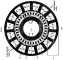
- Figure 1 shows a rotary magnetic gear 100 comprising a first or inner rotor 102, a second or outer rotor 104 and a number of pole pieces 106, otherwise known as an interference or an interference means.
- the first rotor 102 comprises a support 108 bearing a respective first number of permanent magnets 110.
- the first rotor 102 comprises 8 permanent magnets or 4 pole-pairs arranged to produce a spatially varying magnetic field.
- the second rotor 104 comprises a support 112 bearing a respective second number of permanent magnets 114.
- the second rotor 104 illustrated comprises 46 permanent magnets or 23 pole-pairs arranged to produce a spatially varying field.
- the first and second numbers of permanent magnets are different. Accordingly, there will be little or no useful magnetic coupling or interaction between the permanents magnets 112 and 114 such that rotation of one rotor will not cause rotation of the other rotor.
- the pole pieces 106 are used to allow the fields of the permanent magnets 110 and 114 to interact.
- the pole pieces 106 modulate the magnetic fields of the permanent magnets 110 and 114 so they interact to the extent that rotation of one rotor will induce rotation of the other rotor in a geared manner. Rotation of the first rotor at a speed ⁇ 1 will induce rotation of the second rotor at a speed ⁇ 2 where ⁇ 1 > ⁇ 2 and visa versa.
- Figure 2 shows a harmonic spectrum 200 of the spatial distribution of the magnetic flux density of the permanent magnets 110 mounted on the inner rotor 102 of the magnetic gear 100 of figure 1 , in the airgap adjacent to the permanent magnets 114 mounted on the outer rotor 104.
- the spectrum 200 comprises a first or fundamental harmonic 202 associated with the permanent magnets 110 of the first rotor 102.
- the pole pieces 106 modulate the magnetic field of the permanent magnets 110.
- this results in a relatively large asynchronous harmonic 204 having the same number of poles as the permanent magnets 114, which enables coupling between the first 102 and the second 104 rotors such that movement of one induces movement of the other, in a geared manner
- the fundamental component 202 associated with the permanent magnets 110 of the first rotor 102 is always present and is the source of the vast majority of electromagnetic losses associated with magnetic gears.
- Figure 3 shows a known assembly 300 comprising an electrical motor/generator 302 combined with a magnetic gear 304.
- the magnetic gear 304 is substantially similar to that described above with reference to figure 1 .
- Such an assembly is depicted and described in various embodiments in US 6794781 .
- the electrical motor/generator 302 comprises a central armature 306 with respective 3-phase winding 306a-3061.
- the assembly 300 comprises a first or outer rotor 310 comprising permanent magnets 312 mounted on a substrate 314 such as, for example, a back iron.
- the permanent magnets 312 are coupled, in a geared manner, to a number of permanent magnets 316 of a second/inner rotor 318.
- the permanent magnets 316 are mounted on a support 320.
- the magnetic circuit or coupling established between the permanent magnets 316 of the inner rotor 318 and the permanent magnets 312 of the outer rotor 310 is realised using a plurality of pole pieces 322 that are substantially equally circumferentially disposed relative to one another.
- the permanent magnets of the second rotor 318 couple with the 3-phase winding 306a-306l for motor/generator operations.
- the outer rotor 310 is rotatable.
- the pole pieces 322 are fixed, the inner rotor 318 is rotatable and the central armature 306 is fixed.
- FIG. 4 shows the principle of operation of an electrical machine 400 according to embodiments of the present invention.
- the electrical machine 400 comprises a first or inner rotor 402 having a support 404 bearing a first plurality of permanent magnets 406.
- permanent magnets having 10 poles are used.
- embodiments are not limited to using such a number of permanent magnets. Embodiments can be realised that use some other number of permanent magnets.
- the electrical machine 400 comprises a second rotor 408 in the form of a plurality of ferromagnetic pole pieces.
- the pole pieces 408 are arranged to magnetically couple the permanent magnets 406 of the first/inner rotor 402 to a plurality of permanent magnets 410 that are fixed to a number of tooth tips 412 of respective teeth 414 thereby forming a stator 416.
- 60 permanent magnets are fixed to the tooth tips 412.
- the embodiment comprises 15 teeth 414 with respective tooth tips 412. It will be appreciated that embodiments are not limited to such a number of permanent magnets and teeth. Embodiments comprising some other number of permanent magnets and teeth can be realised.
- the pole pieces 408 are rotatable, that is, they form a rotor.
- the inner rotor 402 is rotatable.
- the teeth 414 and associated permanent magnets 410 are fixed.
- the coupling between the permanent magnets 406 and the permanent magnets 410 is realised using the rotatable pole pieces 408.
- Associated with the stator 416 is a plurality of 3-phase windings 1, 1', 2, 2' and 3, 3'.
- the 3-phase windings, and associated currents, are arranged to create magnetic fields that to couple with or form magnetic circuits with the first or fundamental harmonic of the permanent magnets 406 associated with the inner rotor 402.
- the first/fundamental harmonic corresponding to the permanent magnets 406 has 5 pole-pairs.
- Embodiments provide an improved power factor of substantially 0.9 (max. 1), which represents approximately a 200%-300% increase in the power factor of the electrical machine as compared to TFMs.
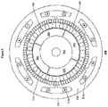
- FIG. 5 shows an electrical machine 500 according to a preferred embodiment of the present invention.
- the electrical machine 500 comprises an inner rotor 502 bearing a number of permanent magnets 504. In the illustrated embodiment, 4 pole permanent magnets are used. However, embodiments can be realised that use some other number of permanent magnets.
- the electrical machine 500 comprises an outer rotor 506 carrying a number of ferromagnetic pole pieces 508. In the illustrated embodiment, the outer rotor 506 carries 23 pole pieces that enable magnetic coupling between the permanent magnets 504 of the inner rotor 502 and a number of permanent magnets 510 that are mounted to a stator 512.
- the stator 512 comprises 3-phase windings 514a-514b associated with each of a plurality of teeth 516.
- the windings magnetically couple with the first harmonic of the permanent magnets 504.
- the winding is 3-phase, but can equally well be some other type of winding such as, for example, 2-phase windings.
- the embodiment illustrated comprises 42 poles of permanents magnets 510 disposed on the stator 512.
- the pole pieces 508 of the outer rotor 506 are arranged to provide gearing between the inner rotor 502 and the outer rotor 506.
- the gearing is such that the inner rotor 502 is a relatively high-speed rotor and the outer rotor 506 is a relatively low speed rotor.
- Preferred embodiments have a gear ratio of 11.5:1.
- Figure 6 shows an axial sectional view 600 of the electrical machine 500 shown in figure 5 .
- the electrical machine 500 comprises a housing 602 that supports, via a plurality of bearings 604, a central spindle 606 on which the inner rotor 502 and associated permanent magnets 504 are mounted for rotation therewith.
- the outer rotor 506, comprising the associated pole pieces 508, is rotatably mounted between the spindle 606 and the housing 602 via respective bearings 608.
- the armature or stator 512 is fixed and disposed outwardly relative to the inner and outer rotors.
- Figure 7 shows a spectrum 700 of the variation of magnetic flux density associated with permanent magnets 504 in the airgap adjacent to the permanent magnets 510 of the preferred embodiment of the electrical machine 500 of figure 5 .
- the spectrum 700 comprises a first harmonic 702 associated with the permanent magnets 504 of the first rotor 502.
- the pole pieces 508 modulate the magnetic field of the permanent magnets 504 and generate a relatively large asynchronous harmonic 704 that has the same number of poles as the permanent magnets 510.
- the first harmonic 702 associated with the permanent magnets 704 of the first rotor 502 couples with the windings 514a-b to establish electromechanical energy conversion, with a torque density comparable to TFMs, but with a much higher power factor
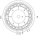
- FIG 8 shows an electrical machine 800 according to a further embodiment.
- the electrical machine 800 comprises an inner rotor 802 bearing a plurality of permanent magnets 804. In the illustrated embodiment, permanent magnets having 4 poles are illustrated but some other number of permanent magnets could equally well be used.
- the inner rotor 802 is preferably a relatively high-speed rotor.
- the electrical machine 800 comprises an outer rotor 806 bearing a plurality of permanent magnets 808. In the illustrated embodiment, permanent magnets 808 having 38 poles form part of the outer rotor 806. However, some other number of poles of permanent magnets 808 could be used.
- the electrical machine 800 comprises a stationary armature 810 bearing a plurality of pole pieces 812 and a 3-phase winding 814.
- the number of pole pieces in the embodiment is 21, although some other number of pole-pieces can be used in embodiments. It should be noted that the embodiment has been illustrated using a 3-phase winding. However, embodiments are not limited thereto. Embodiments can be realised that use some other windings such as, for example, a two phase winding.
- the second/outer rotor 806 forms a relatively low speed rotor that is magnetically coupled, in a geared manner, with the relatively high-speed first/inner rotor 802 via the pole pieces 812 of the stationary armature 810.
- the gear ratio is 19:1 and is related to the number of pole-pairs on the inner rotor 802 and the number of pole pieces.
- Figure 9 shows a spectrum 900 of the variation of magnetic flux density associated with permanent magnets 804 in the airgap adjacent to the permanent magnets 808 of the preferred embodiment of the electrical machine 800 of figure 8 .
- the spectrum 900 comprises a first harmonic 902 associated with the permanent magnets 804 of the first rotor 802.
- the pole pieces 812 modulate the magnetic field of the permanent magnets 804 and generate a relatively large asynchronous harmonic 904 that has the same number of poles as the permanent magnets 808.
- the first or fundamental harmonic 902 associated with the permanent magnets 904 of the first rotor 802 couples with the windings 814 to establish electromechanical energy conversion.
- Embodiments of the present invention can also be realised in the form of radial field rotary electrical machines and axial field rotary electrical machines.
Landscapes
- Engineering & Computer Science (AREA)
- Power Engineering (AREA)
- Permanent Magnet Type Synchronous Machine (AREA)
- Connection Of Motors, Electrical Generators, Mechanical Devices, And The Like (AREA)
- Dynamo-Electric Clutches, Dynamo-Electric Brakes (AREA)
- Permanent Field Magnets Of Synchronous Machinery (AREA)
- Dc Machiner (AREA)
- Control Of Electric Motors In General (AREA)
- Control Of Motors That Do Not Use Commutators (AREA)
- Glass Compositions (AREA)
- Eye Examination Apparatus (AREA)
- Reciprocating, Oscillating Or Vibrating Motors (AREA)
Applications Claiming Priority (2)
| Application Number | Priority Date | Filing Date | Title |
|---|---|---|---|
| GB0607994A GB2437568B (en) | 2006-04-24 | 2006-04-24 | Electrical machines |
| EP07732496.0A EP2011215B1 (fr) | 2006-04-24 | 2007-04-23 | Machines électriques |
Related Parent Applications (2)
| Application Number | Title | Priority Date | Filing Date |
|---|---|---|---|
| EP07732496.0A Division-Into EP2011215B1 (fr) | 2006-04-24 | 2007-04-23 | Machines électriques |
| EP07732496.0A Division EP2011215B1 (fr) | 2006-04-24 | 2007-04-23 | Machines électriques |
Publications (1)
| Publication Number | Publication Date |
|---|---|
| EP3145065A1 true EP3145065A1 (fr) | 2017-03-22 |
Family
ID=36581085
Family Applications (2)
| Application Number | Title | Priority Date | Filing Date |
|---|---|---|---|
| EP07732496.0A Active EP2011215B1 (fr) | 2006-04-24 | 2007-04-23 | Machines électriques |
| EP16181115.3A Withdrawn EP3145065A1 (fr) | 2006-04-24 | 2007-04-23 | Machines électriques |
Family Applications Before (1)
| Application Number | Title | Priority Date | Filing Date |
|---|---|---|---|
| EP07732496.0A Active EP2011215B1 (fr) | 2006-04-24 | 2007-04-23 | Machines électriques |
Country Status (10)
| Country | Link |
|---|---|
| US (2) | US7982351B2 (fr) |
| EP (2) | EP2011215B1 (fr) |
| JP (2) | JP5204094B2 (fr) |
| CN (2) | CN101485068B (fr) |
| CA (1) | CA2650397C (fr) |
| DK (1) | DK2011215T3 (fr) |
| ES (1) | ES2595327T3 (fr) |
| GB (1) | GB2437568B (fr) |
| NO (2) | NO337848B1 (fr) |
| WO (1) | WO2007125284A1 (fr) |
Cited By (1)
| Publication number | Priority date | Publication date | Assignee | Title |
|---|---|---|---|---|
| CN119051386A (zh) * | 2024-11-04 | 2024-11-29 | 中国石油大学(华东) | 一种多级高转速电机 |
Families Citing this family (117)
| Publication number | Priority date | Publication date | Assignee | Title |
|---|---|---|---|---|
| US5131971A (en) | 1991-01-14 | 1992-07-21 | Elia Gerardo P | Apparatus for making a reinforced fabric from a ribbon of uncured elastomeric material |
| GB2457226B (en) * | 2008-01-11 | 2013-01-09 | Magnomatics Ltd | Drives for sealed systems |
| GB0810097D0 (en) * | 2008-06-03 | 2008-07-09 | Magnomatics Ltd | Magnetic gear |
| GB2457682B (en) * | 2008-02-21 | 2012-03-28 | Magnomatics Ltd | Variable magnetic gears |
| GB0807388D0 (en) | 2008-04-23 | 2008-05-28 | Magnomatics Ltd | Electrical machines |
| GB0813173D0 (en) * | 2008-02-21 | 2008-08-27 | Magnomatics Ltd | Wind turbine power train |
| GB0810096D0 (en) * | 2008-06-03 | 2008-07-09 | Magnomatics Ltd | Electrical machines |
| CN101976905B (zh) * | 2008-04-21 | 2013-03-20 | 许晓华 | 直接驱动复合型永磁电机 |
| US20090288893A1 (en) * | 2008-05-09 | 2009-11-26 | John C. Wyall | Controllerless electric drive system |
| GB0808524D0 (en) * | 2008-05-12 | 2008-06-18 | Magnomatics Ltd | Magnetic pole-piece structure |
| US8847464B2 (en) * | 2008-06-12 | 2014-09-30 | General Electric Company | Electrical machine with improved stator flux pattern across a rotor that permits higher torque density |
| US20100032952A1 (en) * | 2008-08-08 | 2010-02-11 | Hatch Gareth P | Turbine generator having direct magnetic gear drive |
| EP2161821B1 (fr) | 2008-09-03 | 2020-06-17 | General Electric Company | Générateur à commande magnétique |
| US7804215B2 (en) * | 2008-09-30 | 2010-09-28 | General Electric Company | Integrated cooling concept for magnetically geared machine |
| WO2010082893A1 (fr) | 2009-01-15 | 2010-07-22 | Volvo Technology Corporation | Turborécupérateur à répartition de la puissance moteur à transmission à variation continue électromagnétique et moteur et véhicule comportant un tel turborécupérateur |
| ITBO20090075A1 (it) * | 2009-02-13 | 2010-08-14 | Magneti Marelli Spa | Macchina elettrica con singolo statore e due rotori tra loro indipendenti e veicolo stradale provvisto di tale macchina elettrica |
| GB2468888B (en) * | 2009-03-26 | 2013-11-06 | Magnomatics Ltd | Marine propulsion device with an electrical machine having integral magnetic gearing |
| GB0905343D0 (en) | 2009-03-27 | 2009-05-13 | Ricardo Uk Ltd | A flywheel |
| GB0905345D0 (en) | 2009-03-27 | 2009-05-13 | Ricardo Uk Ltd | A flywheel |
| GB0905344D0 (en) | 2009-03-27 | 2009-05-13 | Ricardo Uk Ltd | A flywheel |
| DE102009024261B4 (de) | 2009-06-05 | 2014-10-16 | Sew-Eurodrive Gmbh & Co Kg | Elektrische Maschine |
| EP2502336A2 (fr) | 2009-11-17 | 2012-09-26 | Ricardo Uk Limited | Élément de couplage |
| GB0920148D0 (en) * | 2009-11-17 | 2009-12-30 | Magnomatics Ltd | Magnetically geared machine for marine generation |
| TWI406480B (zh) * | 2010-01-13 | 2013-08-21 | Ind Tech Res Inst | 變速裝置 |
| CN102195442B (zh) * | 2010-03-05 | 2013-09-04 | 江建中 | 磁场调制式磁性齿轮 |
| EP2572440B1 (fr) | 2010-05-17 | 2021-10-20 | Magnomatics Limited | Engrenage magnétique |
| US9127589B2 (en) * | 2010-06-22 | 2015-09-08 | Volvo Lastvagnar Ab | Turbo compound transmission and a method for controlling a turbo compound transmission |
| FR2963501B1 (fr) * | 2010-07-29 | 2012-08-31 | Valeo Equip Electr Moteur | Machine electrique tournante synchrone avec rotor a double excitation |
| RU2437196C1 (ru) * | 2010-10-05 | 2011-12-20 | Андрей Борисович Захаренко | Электрическая машина двойного вращения |
| US20120098374A1 (en) * | 2010-10-25 | 2012-04-26 | Alvaro Jorge Mari Curbelo | Variable-speed magnetic coupling and method for control |
| GB201019473D0 (en) | 2010-11-17 | 2010-12-29 | Ricardo Uk Ltd | An improved coupler |
| US8319365B2 (en) * | 2010-12-17 | 2012-11-27 | General Electric Company | System and method to provide constant speed mechanical output in a machine |
| CN102032119A (zh) * | 2010-12-20 | 2011-04-27 | 中国科学院深圳先进技术研究院 | 一种集成磁性齿轮外转子风力发电机 |
| US20130342057A1 (en) * | 2011-01-17 | 2013-12-26 | Lord Corporation | Linear-rotating magnet energy harvester |
| JP5286373B2 (ja) * | 2011-01-28 | 2013-09-11 | 株式会社日立製作所 | 磁気歯車 |
| GB201101678D0 (en) | 2011-02-01 | 2011-03-16 | Rolls Royce Plc | A cooling arrangement for a magnetic gearbox |
| GB2488129A (en) | 2011-02-16 | 2012-08-22 | Rolls Royce Plc | Modulated field electromagnetic machine |
| JP5722690B2 (ja) * | 2011-04-19 | 2015-05-27 | T.K Leverage株式会社 | 発電装置 |
| GB201106768D0 (en) | 2011-04-20 | 2011-06-01 | Ricardo Uk Ltd | An energy storage system |
| CN103609008B (zh) * | 2011-06-09 | 2016-04-20 | 东芝三菱电机产业系统株式会社 | 旋转电机 |
| WO2013001557A1 (fr) * | 2011-06-27 | 2013-01-03 | 株式会社 日立製作所 | Machine tournante électrique du type à engrenage magnétique |
| CN102868268A (zh) * | 2011-07-03 | 2013-01-09 | 余虹锦 | 新型双鼠笼结构的气隙磁场电磁调制式永磁电机 |
| US9853532B2 (en) | 2011-07-22 | 2017-12-26 | Regal Beloit America, Inc. | Magnetic transmission |
| US8575810B2 (en) * | 2011-07-29 | 2013-11-05 | Panasonic Corporation | Motor |
| US9559557B2 (en) | 2011-08-11 | 2017-01-31 | Toshiba Mitsubishi-Electric Industrial Systems Corporation | Rotating electrical machine |
| JP5858399B2 (ja) * | 2011-11-11 | 2016-02-10 | 国立大学法人大阪大学 | 磁気減速機構及び低速ロータ磁気減速回転制御方法 |
| WO2013091669A1 (fr) * | 2011-12-21 | 2013-06-27 | Volvo Lastvagnar Ab | Transmission turbo compound et procédé pour commander une transmission turbo compound |
| EP2629407B1 (fr) * | 2012-02-17 | 2014-12-24 | Bell Helicopter Textron Inc. | Générateur électrique pour structure de rotation |
| JP6218759B2 (ja) * | 2012-03-12 | 2017-10-25 | シェフラー テクノロジーズ アー・ゲー ウント コー. カー・ゲーSchaeffler Technologies AG & Co. KG | トルク伝達装置用の操作装置 |
| CN103378711B (zh) * | 2012-04-17 | 2015-05-06 | 余虹锦 | 双机械端口磁导谐波式电磁齿轮复合永磁电机 |
| GB2508416A (en) | 2012-11-30 | 2014-06-04 | Univ Sheffield | Reducing dominant undesirable harmonics in an electric machine |
| JP6093592B2 (ja) | 2013-02-22 | 2017-03-08 | 株式会社Ihi | 磁気波動歯車装置 |
| GB201308270D0 (en) | 2013-05-08 | 2013-06-12 | Magnomatics Ltd | Methods and apparatus for rotor position estimation |
| DE102014115826B4 (de) | 2013-12-03 | 2024-10-10 | Osaka University | Fahrrad-Dynamo |
| WO2015103781A1 (fr) * | 2014-01-13 | 2015-07-16 | 卢敏 | Moteur composite à courant alternatif triphasé, à transmission électromagnétique par ondes harmoniques de conductance magnétique et à pôles saillants |
| US10418927B2 (en) | 2014-02-11 | 2019-09-17 | Magnomatics Limited | Magnetic gear system and method for reducing transmission of torque pulsation |
| JP6265569B2 (ja) * | 2014-03-12 | 2018-01-24 | 株式会社Ihi | 環状磁極部材及び磁気波動歯車装置 |
| DE102014104494A1 (de) | 2014-03-31 | 2015-10-01 | Momentum Technologies Gmbh | Antriebssystem mit Elektromotor und Getriebe |
| JP6257114B2 (ja) * | 2014-05-20 | 2018-01-10 | 株式会社Ihi | 磁気波動歯車装置 |
| CN104065242B (zh) * | 2014-06-27 | 2017-01-25 | 南京艾凌节能技术有限公司 | 一种一体化永磁变速减速机 |
| WO2016108882A1 (fr) * | 2014-12-31 | 2016-07-07 | Halliburton Energy Services, Inc. | Trépan à générateur d'énergie électrique |
| US9667126B2 (en) * | 2015-01-05 | 2017-05-30 | Langham Automatic Co., Ltd. | Motor |
| CN104600930B (zh) * | 2015-01-08 | 2017-06-16 | 东南大学 | 永磁励磁无刷双馈风力发电机 |
| EP3294623B1 (fr) | 2015-05-08 | 2019-04-17 | Rolls-Royce AB | Dispositif de propulsion de navire maritime, unité de nacelle et navire maritime |
| US10724999B2 (en) | 2015-06-04 | 2020-07-28 | Rolls-Royce Corporation | Thermal spray diagnostics |
| GB2539202A (en) * | 2015-06-08 | 2016-12-14 | Elumotion Ltd | Rotary actuator |
| CN104901510B (zh) * | 2015-07-01 | 2018-02-13 | 大连交通大学 | 一种永磁齿轮传动装置 |
| GB201520131D0 (en) | 2015-11-16 | 2015-12-30 | Rolls Royce Plc | Variable gear ratio electrical machine |
| GB2549448A (en) * | 2016-01-13 | 2017-10-25 | Magnomatics Ltd | A magnetically geared apparatus |
| JP2019523196A (ja) | 2016-07-14 | 2019-08-22 | フレックスリンク アーベー | コンベヤのための磁気変速機 |
| US10513986B2 (en) | 2016-10-05 | 2019-12-24 | Rolls-Royce North American Technologies, Inc. | Counter-rotating electric generator in turbine engine |
| US10312781B2 (en) * | 2016-10-05 | 2019-06-04 | Rolls-Royce North American Technologies, Inc. | Multiple coil electric generator in turbine engine |
| JP6954581B2 (ja) * | 2016-11-11 | 2021-10-27 | 株式会社プロスパイン | 回転増速部を有する発電機 |
| US10505431B1 (en) | 2017-03-06 | 2019-12-10 | Harold O. Hosea | Brushless dual rotor electromagnetic induction motor |
| CN107070031B (zh) * | 2017-05-15 | 2020-07-14 | 华中科技大学 | 一种转子、定子及多工作谐波永磁电机 |
| ES2941256T3 (es) | 2018-01-12 | 2023-05-19 | Carrier Corp | Máquina electromagnética sin núcleo con doble rotor |
| DE102018110151A1 (de) * | 2018-04-26 | 2019-10-31 | Linz Center Of Mechatronics Gmbh | Elektrische Maschine mit Elektromotor und Magnetgetriebe |
| RU2706797C1 (ru) * | 2018-06-21 | 2019-11-21 | Общество С Ограниченной Ответственностью "Научно-Производственное Предприятие Электромеханические Технологии" | Магнитный редуктор |
| KR102062461B1 (ko) * | 2018-07-30 | 2020-02-20 | 한국교통대학교산학협력단 | 마그네틱 기어드 동기전동기의 코깅토크 저감을 위한 스큐각 도출 방법 |
| DE102018133718A1 (de) * | 2018-12-31 | 2020-07-02 | Henk B.V. | Transportvorrichtung zum Transport wenigstens eines Gegenstands und/oder einer Person |
| CN111525768B (zh) * | 2019-02-01 | 2023-02-28 | 香港中文大学 | 人体动能收集装置及其转换方法 |
| JP7361344B2 (ja) * | 2019-02-26 | 2023-10-16 | パナソニックIpマネジメント株式会社 | 磁気ギアードモータ |
| US11046404B2 (en) * | 2019-07-31 | 2021-06-29 | Abb Schweiz Ag | Dual propeller drive system for a ship |
| US11296588B2 (en) * | 2019-10-15 | 2022-04-05 | Darrell Schmidt Enterprises, Inc. | Magnetic coupler |
| CN112803691B (zh) | 2019-11-13 | 2025-06-03 | 通用汽车环球科技运作有限责任公司 | 带分布式绕组的轴向磁通马达 |
| CN112821702B (zh) | 2019-11-15 | 2025-02-25 | 通用汽车环球科技运作有限责任公司 | 用于轴向磁通马达的混合定子芯部件设计 |
| JP7493340B2 (ja) * | 2020-01-17 | 2024-05-31 | 三菱重工業株式会社 | 電動車両 |
| JP7365250B2 (ja) * | 2020-01-24 | 2023-10-19 | 三菱重工業株式会社 | 磁気ギアード回転電機、及びステータの製造方法 |
| JP7413042B2 (ja) | 2020-01-24 | 2024-01-15 | 三菱重工業株式会社 | 外径側磁石界磁及び磁気歯車 |
| WO2021189050A1 (fr) * | 2020-03-20 | 2021-09-23 | Sanders Daniel Lee | Machine électrique à noyau universel |
| CN114552815B (zh) | 2020-11-26 | 2025-05-02 | 通用汽车环球科技运作有限责任公司 | 轴向磁通电机定子的直接接触冷却 |
| CN112615517A (zh) * | 2020-11-30 | 2021-04-06 | 珠海格力电器股份有限公司 | 磁齿轮组件及具有其的复合电机 |
| CN112491247B (zh) * | 2020-11-30 | 2025-09-19 | 珠海格力电器股份有限公司 | 调磁环结构、磁齿轮组件和复合电机 |
| CN116490706A (zh) * | 2020-12-02 | 2023-07-25 | 松下知识产权经营株式会社 | 磁齿轮电机和磁齿轮 |
| CN116670985A (zh) | 2020-12-23 | 2023-08-29 | 三菱电机株式会社 | 永磁式旋转电机 |
| CN112713737B (zh) * | 2020-12-31 | 2025-07-01 | 江南大学 | 一种面向机器人关节的二级磁齿轮传动电机 |
| DE202021100986U1 (de) | 2021-02-26 | 2022-05-31 | Frank Ranostaj | Fahrrad-Unterstützungsantrieb, insbesondere mit einem Elektroantrieb, insbesondere für ein Fahrrad |
| JP7595496B2 (ja) | 2021-03-22 | 2024-12-06 | 三菱重工業株式会社 | 磁気ギアード回転機械、及び発電システム |
| JP7610218B2 (ja) | 2021-03-30 | 2025-01-08 | 三菱重工業株式会社 | 磁気ギアード回転機械、発電システム、および磁極片回転子 |
| US20240283346A1 (en) * | 2021-06-14 | 2024-08-22 | Nanyang Technological University | Flux-modulated machine |
| JP7679012B2 (ja) | 2021-09-14 | 2025-05-19 | 三菱重工業株式会社 | 磁気ギアード回転機械、発電システム、および、駆動システム |
| JP2024545026A (ja) * | 2021-12-02 | 2024-12-05 | モラン、マシュー | 高効率機械 |
| DE102022203842A1 (de) | 2022-04-19 | 2023-10-19 | Zf Friedrichshafen Ag | Elektromotorvorrichtung |
| JP2024047200A (ja) | 2022-09-26 | 2024-04-05 | 三菱重工業株式会社 | ステータ、および、ステータの製造方法 |
| WO2025207685A1 (fr) * | 2024-03-26 | 2025-10-02 | The Texas A & M University System | Machine à engrenage magnétique intégrée |
| PL448911A1 (pl) * | 2024-06-20 | 2025-05-12 | Zachodniopomorski Uniwersytet Technologiczny W Szczecinie | Wysokomomentowa maszyna z przekładnią magnetyczną |
| PL448904A1 (pl) * | 2024-06-20 | 2025-04-28 | Zachodniopomorski Uniwersytet Technologiczny W Szczecinie | Wysokomomentowa maszyna z przekładnią magnetyczną |
| PL448909A1 (pl) * | 2024-06-20 | 2025-05-12 | Zachodniopomorski Uniwersytet Technologiczny W Szczecinie | Wysokomomentowa maszyna z przekładnią magnetyczną |
| PL448910A1 (pl) * | 2024-06-20 | 2025-05-12 | Zachodniopomorski Uniwersytet Technologiczny W Szczecinie | Wysokomomentowa maszyna z przekładnią magnetyczną |
| PL448913A1 (pl) * | 2024-06-20 | 2025-05-12 | Zachodniopomorski Uniwersytet Technologiczny W Szczecinie | Wysokomomentowa maszyna z przekładnią magnetyczną |
| PL448900A1 (pl) * | 2024-06-20 | 2025-04-28 | Zachodniopomorski Uniwersytet Technologiczny W Szczecinie | Wysokomomentowa maszyna z przekładnią magnetyczną |
| PL448899A1 (pl) * | 2024-06-20 | 2025-05-12 | Zachodniopomorski Uniwersytet Technologiczny W Szczecinie | Wysokomomentowa maszyna z przekładnią magnetyczną |
| PL448912A1 (pl) * | 2024-06-20 | 2025-05-12 | Zachodniopomorski Uniwersytet Technologiczny W Szczecinie | Wysokomomentowa maszyna z przekładnią magnetyczną |
| PL448902A1 (pl) * | 2024-06-20 | 2025-04-28 | Zachodniopomorski Uniwersytet Technologiczny W Szczecinie | Wysokomomentowa maszyna z przekładnią magnetyczną |
| PL448901A1 (pl) * | 2024-06-20 | 2025-04-28 | Zachodniopomorski Uniwersytet Technologiczny W Szczecinie | Wysokomomentowa maszyna z przekładnią magnetyczną |
| PL448903A1 (pl) * | 2024-06-20 | 2025-04-28 | Zachodniopomorski Uniwersytet Technologiczny W Szczecinie | Wysokomomentowa maszyna z przekładnią magnetyczną |
| PL448914A1 (pl) * | 2024-06-20 | 2025-05-12 | Zachodniopomorski Uniwersytet Technologiczny W Szczecinie | Wysokomomentowa maszyna z przekładnią magnetyczną |
Citations (6)
| Publication number | Priority date | Publication date | Assignee | Title |
|---|---|---|---|---|
| EP0945963A2 (fr) * | 1998-03-25 | 1999-09-29 | Nissan Motor Co., Ltd. | Moteur/générateur |
| EP1117173A2 (fr) * | 2000-01-17 | 2001-07-18 | Nissan Motor Company Limited | Moteur-Générateur |
| EP1353436A2 (fr) * | 2002-04-13 | 2003-10-15 | ROLLS-ROYCE plc | Machine électrique compacte |
| US20040119373A1 (en) * | 2002-04-01 | 2004-06-24 | Kan Akatsu | Electrical rotating machine having two rotors driven by means of compound current |
| WO2004079884A1 (fr) * | 2003-03-07 | 2004-09-16 | Kabushiki Kaisha Yaskawa Denki | Dispositif d'entrainement sous vide et systeme de transport utilisant ledit dispositif |
| EP1528659A2 (fr) * | 2003-10-10 | 2005-05-04 | Nissan Motor Co., Ltd. | Structure de circuit magnétique pour machine électrique tournante |
Family Cites Families (23)
| Publication number | Priority date | Publication date | Assignee | Title |
|---|---|---|---|---|
| DE2417054C3 (de) | 1974-04-08 | 1983-02-10 | Siemens AG, 1000 Berlin und 8000 München | Schaltungsanordnung mit zwei miteinander verknüpften Schaltkreissystemen |
| FR2517137B1 (fr) | 1981-11-25 | 1985-11-15 | Cibie Pierre | Machine electrique tournante formant notamment variateur de vitesse ou convertisseur de couple |
| GB9309689D0 (en) * | 1993-05-11 | 1993-06-23 | Flack Roy E | Electromagnetic transimssion systems,motors and generators |
| DE4405701A1 (de) * | 1994-02-23 | 1995-08-24 | Philips Patentverwaltung | Magnetisches Getriebe mit mehreren magnetisch zusammenwirkenden, relativ zueinander beweglichen Teilen |
| DE4408719C1 (de) | 1994-03-15 | 1995-07-06 | Volkswagen Ag | Generator-Motor-Kombination |
| JP3427511B2 (ja) * | 1994-10-11 | 2003-07-22 | 株式会社デンソー | 二軸出力型電動機 |
| FR2742939B1 (fr) * | 1995-12-21 | 1998-03-06 | Jeumont Ind | Machine electrique modulaire de type discoide |
| US5793136A (en) * | 1996-06-05 | 1998-08-11 | Redzic; Sabid | Differential motor/generator apparatus |
| DE19652490A1 (de) * | 1996-12-17 | 1998-06-18 | Philips Patentverwaltung | Magnetisches Getriebe |
| US6121705A (en) * | 1996-12-31 | 2000-09-19 | Hoong; Fong Chean | Alternating pole AC motor/generator with two inner rotating rotors and an external static stator |
| DE19743380C1 (de) | 1997-09-30 | 1999-03-25 | Emf 97 Gmbh | Reluktanzmotor |
| JP3480302B2 (ja) * | 1998-03-25 | 2003-12-15 | 日産自動車株式会社 | 回転電機 |
| JP2000060091A (ja) * | 1998-08-06 | 2000-02-25 | Ebara Corp | 回転電機 |
| JP3480439B2 (ja) * | 1999-09-27 | 2003-12-22 | 日産自動車株式会社 | 回転電機の制御装置 |
| JP3580194B2 (ja) * | 1999-10-04 | 2004-10-20 | 日産自動車株式会社 | 回転電機の組付け構造 |
| JP4269544B2 (ja) * | 2000-09-14 | 2009-05-27 | 株式会社デンソー | 複数ロータ型同期機 |
| US7259492B2 (en) * | 2001-09-27 | 2007-08-21 | Tai-Her Yang | Rotor axial activation modulation of electric machinery due to reverse torque |
| AUPS083702A0 (en) * | 2002-03-04 | 2002-03-21 | Darday, Stephen | Magnetic torque converter |
| JP2003281858A (ja) * | 2002-03-22 | 2003-10-03 | Alpine Electronics Inc | ディスク再生装置 |
| JP3671929B2 (ja) * | 2002-04-01 | 2005-07-13 | 日産自動車株式会社 | 回転電機 |
| JP4225001B2 (ja) * | 2002-08-09 | 2009-02-18 | 株式会社エクォス・リサーチ | 電動機 |
| CN1284211C (zh) | 2002-12-03 | 2006-11-08 | 旺宏电子股份有限公司 | 利用研磨垫整理装置整理研磨垫的方法 |
| EP1860754A1 (fr) * | 2006-05-24 | 2007-11-28 | HONDA MOTOR CO., Ltd. | Moteur électrique |
-
2006
- 2006-04-24 GB GB0607994A patent/GB2437568B/en not_active Expired - Lifetime
-
2007
- 2007-04-23 CA CA2650397A patent/CA2650397C/fr active Active
- 2007-04-23 EP EP07732496.0A patent/EP2011215B1/fr active Active
- 2007-04-23 ES ES07732496.0T patent/ES2595327T3/es active Active
- 2007-04-23 CN CN200780023491XA patent/CN101485068B/zh active Active
- 2007-04-23 EP EP16181115.3A patent/EP3145065A1/fr not_active Withdrawn
- 2007-04-23 CN CN201210153629.0A patent/CN103001425B/zh active Active
- 2007-04-23 WO PCT/GB2007/001456 patent/WO2007125284A1/fr not_active Ceased
- 2007-04-23 JP JP2009507143A patent/JP5204094B2/ja active Active
- 2007-04-23 US US12/298,444 patent/US7982351B2/en active Active
- 2007-04-23 DK DK07732496.0T patent/DK2011215T3/da active
-
2008
- 2008-10-29 NO NO20084594A patent/NO337848B1/no unknown
-
2011
- 2011-06-10 US US13/157,720 patent/US8466592B2/en active Active
-
2013
- 2013-02-14 JP JP2013026690A patent/JP5643857B2/ja active Active
-
2016
- 2016-01-15 NO NO20160079A patent/NO340196B1/no not_active IP Right Cessation
Patent Citations (6)
| Publication number | Priority date | Publication date | Assignee | Title |
|---|---|---|---|---|
| EP0945963A2 (fr) * | 1998-03-25 | 1999-09-29 | Nissan Motor Co., Ltd. | Moteur/générateur |
| EP1117173A2 (fr) * | 2000-01-17 | 2001-07-18 | Nissan Motor Company Limited | Moteur-Générateur |
| US20040119373A1 (en) * | 2002-04-01 | 2004-06-24 | Kan Akatsu | Electrical rotating machine having two rotors driven by means of compound current |
| EP1353436A2 (fr) * | 2002-04-13 | 2003-10-15 | ROLLS-ROYCE plc | Machine électrique compacte |
| WO2004079884A1 (fr) * | 2003-03-07 | 2004-09-16 | Kabushiki Kaisha Yaskawa Denki | Dispositif d'entrainement sous vide et systeme de transport utilisant ledit dispositif |
| EP1528659A2 (fr) * | 2003-10-10 | 2005-05-04 | Nissan Motor Co., Ltd. | Structure de circuit magnétique pour machine électrique tournante |
Cited By (1)
| Publication number | Priority date | Publication date | Assignee | Title |
|---|---|---|---|---|
| CN119051386A (zh) * | 2024-11-04 | 2024-11-29 | 中国石油大学(华东) | 一种多级高转速电机 |
Also Published As
| Publication number | Publication date |
|---|---|
| CN101485068B (zh) | 2012-07-04 |
| NO337848B1 (no) | 2016-06-27 |
| US7982351B2 (en) | 2011-07-19 |
| CN101485068A (zh) | 2009-07-15 |
| JP5643857B2 (ja) | 2014-12-17 |
| NO340196B1 (no) | 2017-03-20 |
| JP2013141400A (ja) | 2013-07-18 |
| ES2595327T3 (es) | 2016-12-29 |
| EP2011215B1 (fr) | 2016-08-31 |
| US8466592B2 (en) | 2013-06-18 |
| GB0607994D0 (en) | 2006-05-31 |
| JP5204094B2 (ja) | 2013-06-05 |
| CN103001425B (zh) | 2015-08-26 |
| CA2650397C (fr) | 2020-04-07 |
| NO20160079L (no) | 2009-01-22 |
| CA2650397A1 (fr) | 2007-11-08 |
| US20100283345A1 (en) | 2010-11-11 |
| WO2007125284A1 (fr) | 2007-11-08 |
| EP2011215A1 (fr) | 2009-01-07 |
| JP2009535012A (ja) | 2009-09-24 |
| GB2437568B (en) | 2009-02-11 |
| NO20084594L (no) | 2009-01-22 |
| US20120146442A1 (en) | 2012-06-14 |
| DK2011215T3 (da) | 2017-01-02 |
| GB2437568A (en) | 2007-10-31 |
| CN103001425A (zh) | 2013-03-27 |
Similar Documents
| Publication | Publication Date | Title |
|---|---|---|
| EP2011215B1 (fr) | Machines électriques | |
| US9496768B2 (en) | Electrical machines | |
| US7385330B2 (en) | Permanent-magnet switched-flux machine | |
| US20110042965A1 (en) | Wind turbine power train | |
| US20110115326A1 (en) | Electrical machines | |
| EP2676359A2 (fr) | Machine électrique | |
| Chirca et al. | Analysis of innovative design variations for double-sided coreless-stator axial-flux permanent-magnet generators in micro-wind power applications | |
| Shrivastava et al. | A novel dual magnetically geared halbach array based tubular linear permanent magnet generator for wave energy conversion | |
| US20100026103A1 (en) | Driving or power generating multiple phase electric machine | |
| Du et al. | A linear magnetic-geared permanent magnet machine for wave energy generation | |
| CN101355287A (zh) | 惯性永磁发电机 | |
| Zhu et al. | A novel magnetic-geared doubly salient permanent magnet machine for low-speed high-torque applications | |
| Trzynadlowski et al. | Permanent-magnet switched-flux machine |
Legal Events
| Date | Code | Title | Description |
|---|---|---|---|
| PUAI | Public reference made under article 153(3) epc to a published international application that has entered the european phase |
Free format text: ORIGINAL CODE: 0009012 |
|
| AC | Divisional application: reference to earlier application |
Ref document number: 2011215 Country of ref document: EP Kind code of ref document: P |
|
| AK | Designated contracting states |
Kind code of ref document: A1 Designated state(s): AT BE BG CH CY CZ DE DK EE ES FI FR GB GR HU IE IS IT LI LT LU LV MC MT NL PL PT RO SE SI SK TR |
|
| 17P | Request for examination filed |
Effective date: 20170915 |
|
| RBV | Designated contracting states (corrected) |
Designated state(s): AT BE BG CH CY CZ DE DK EE ES FI FR GB GR HU IE IS IT LI LT LU LV MC MT NL PL PT RO SE SI SK TR |
|
| STAA | Information on the status of an ep patent application or granted ep patent |
Free format text: STATUS: THE APPLICATION IS DEEMED TO BE WITHDRAWN |
|
| 18D | Application deemed to be withdrawn |
Effective date: 20181101 |