EP3145089A1 - Procédé d'émission, procédé de réception, dispositif d'émission et dispositif de réception - Google Patents
Procédé d'émission, procédé de réception, dispositif d'émission et dispositif de réception Download PDFInfo
- Publication number
- EP3145089A1 EP3145089A1 EP15792823.5A EP15792823A EP3145089A1 EP 3145089 A1 EP3145089 A1 EP 3145089A1 EP 15792823 A EP15792823 A EP 15792823A EP 3145089 A1 EP3145089 A1 EP 3145089A1
- Authority
- EP
- European Patent Office
- Prior art keywords
- bits
- coding rate
- coding
- information
- error correction
- Prior art date
- Legal status (The legal status is an assumption and is not a legal conclusion. Google has not performed a legal analysis and makes no representation as to the accuracy of the status listed.)
- Withdrawn
Links
- 238000000034 method Methods 0.000 title claims abstract description 724
- 230000005540 biological transmission Effects 0.000 title claims description 186
- 239000011159 matrix material Substances 0.000 claims abstract description 90
- 238000012545 processing Methods 0.000 claims abstract description 46
- 238000012937 correction Methods 0.000 claims description 440
- 238000004891 communication Methods 0.000 description 25
- 238000013507 mapping Methods 0.000 description 5
- 230000010363 phase shift Effects 0.000 description 5
- 238000006243 chemical reaction Methods 0.000 description 4
- 238000005516 engineering process Methods 0.000 description 4
- 239000000284 extract Substances 0.000 description 4
- 230000006870 function Effects 0.000 description 4
- 238000003780 insertion Methods 0.000 description 4
- 230000037431 insertion Effects 0.000 description 4
- 230000010354 integration Effects 0.000 description 4
- 239000000969 carrier Substances 0.000 description 3
- 238000001514 detection method Methods 0.000 description 3
- 230000008859 change Effects 0.000 description 2
- 230000000694 effects Effects 0.000 description 2
- 230000003287 optical effect Effects 0.000 description 2
- NRNCYVBFPDDJNE-UHFFFAOYSA-N pemoline Chemical compound O1C(N)=NC(=O)C1C1=CC=CC=C1 NRNCYVBFPDDJNE-UHFFFAOYSA-N 0.000 description 2
- 238000003860 storage Methods 0.000 description 2
- 230000006978 adaptation Effects 0.000 description 1
- 230000003321 amplification Effects 0.000 description 1
- 230000008901 benefit Effects 0.000 description 1
- 238000010276 construction Methods 0.000 description 1
- 230000006866 deterioration Effects 0.000 description 1
- 238000011161 development Methods 0.000 description 1
- 238000009432 framing Methods 0.000 description 1
- 238000004519 manufacturing process Methods 0.000 description 1
- 238000012986 modification Methods 0.000 description 1
- 230000004048 modification Effects 0.000 description 1
- 238000003199 nucleic acid amplification method Methods 0.000 description 1
- 239000004065 semiconductor Substances 0.000 description 1
- 238000001228 spectrum Methods 0.000 description 1
- 230000007480 spreading Effects 0.000 description 1
- 238000003892 spreading Methods 0.000 description 1
Images








Classifications
-
- H—ELECTRICITY
- H04—ELECTRIC COMMUNICATION TECHNIQUE
- H04L—TRANSMISSION OF DIGITAL INFORMATION, e.g. TELEGRAPHIC COMMUNICATION
- H04L1/00—Arrangements for detecting or preventing errors in the information received
- H04L1/004—Arrangements for detecting or preventing errors in the information received by using forward error control
- H04L1/0041—Arrangements at the transmitter end
-
- H—ELECTRICITY
- H03—ELECTRONIC CIRCUITRY
- H03M—CODING; DECODING; CODE CONVERSION IN GENERAL
- H03M13/00—Coding, decoding or code conversion, for error detection or error correction; Coding theory basic assumptions; Coding bounds; Error probability evaluation methods; Channel models; Simulation or testing of codes
- H03M13/03—Error detection or forward error correction by redundancy in data representation, i.e. code words containing more digits than the source words
- H03M13/05—Error detection or forward error correction by redundancy in data representation, i.e. code words containing more digits than the source words using block codes, i.e. a predetermined number of check bits joined to a predetermined number of information bits
- H03M13/11—Error detection or forward error correction by redundancy in data representation, i.e. code words containing more digits than the source words using block codes, i.e. a predetermined number of check bits joined to a predetermined number of information bits using multiple parity bits
- H03M13/1102—Codes on graphs and decoding on graphs, e.g. low-density parity check [LDPC] codes
-
- H—ELECTRICITY
- H03—ELECTRONIC CIRCUITRY
- H03M—CODING; DECODING; CODE CONVERSION IN GENERAL
- H03M13/00—Coding, decoding or code conversion, for error detection or error correction; Coding theory basic assumptions; Coding bounds; Error probability evaluation methods; Channel models; Simulation or testing of codes
- H03M13/63—Joint error correction and other techniques
- H03M13/635—Error control coding in combination with rate matching
- H03M13/6362—Error control coding in combination with rate matching by puncturing
-
- H—ELECTRICITY
- H03—ELECTRONIC CIRCUITRY
- H03M—CODING; DECODING; CODE CONVERSION IN GENERAL
- H03M13/00—Coding, decoding or code conversion, for error detection or error correction; Coding theory basic assumptions; Coding bounds; Error probability evaluation methods; Channel models; Simulation or testing of codes
- H03M13/65—Purpose and implementation aspects
- H03M13/6508—Flexibility, adaptability, parametrability and configurability of the implementation
- H03M13/6516—Support of multiple code parameters, e.g. generalized Reed-Solomon decoder for a variety of generator polynomials or Galois fields
-
- H—ELECTRICITY
- H04—ELECTRIC COMMUNICATION TECHNIQUE
- H04L—TRANSMISSION OF DIGITAL INFORMATION, e.g. TELEGRAPHIC COMMUNICATION
- H04L1/00—Arrangements for detecting or preventing errors in the information received
- H04L1/004—Arrangements for detecting or preventing errors in the information received by using forward error control
- H04L1/0056—Systems characterized by the type of code used
- H04L1/0057—Block codes
-
- H—ELECTRICITY
- H04—ELECTRIC COMMUNICATION TECHNIQUE
- H04L—TRANSMISSION OF DIGITAL INFORMATION, e.g. TELEGRAPHIC COMMUNICATION
- H04L1/00—Arrangements for detecting or preventing errors in the information received
- H04L1/004—Arrangements for detecting or preventing errors in the information received by using forward error control
- H04L1/0056—Systems characterized by the type of code used
- H04L1/0067—Rate matching
- H04L1/0068—Rate matching by puncturing
Definitions
- the present disclosure relates to a broadcast and communication system which uses error correction codes.
- error correction codes are used in order to improve data reception quality at a reception device.
- an arithmetic operation scale it is desirable to use an error correction code of high correction performance.
- LDPC Low-Density Parity-Check
- a broadcast and communication system which uses radio waves and cables.
- a block length (code length) of an LDPC code and a coding rate are variable.
- NPL 1 describes encoding an information sequence and generating and transmitting a codeword of N bits by using an LDPC code defined by parity check matrix H1 (where a number of columns is N).
- NPL 2 describes encoding an information sequence and generating a codeword of L bits by using an LDPC code defined by parity check matrix H2 (where a number of columns is L and a relationship of N ⁇ L holds). Then, NPL 2 describes determining bits not to be transmitted of L - N bits in the codeword of the L bits, and transmitting a sequence of a rest of N bits (puncturing method).
- the transmission method includes an encoding step of selecting one coding method from a plurality of coding methods per data symbol group, encoding an information sequence by using the selected coding method to obtain an encoded sequence, a modulation step of modulating the encoded sequence to obtain data symbols, and a transmission step of transmitting a transmission frame that includes a plurality of data symbol groups, each of the plurality of data symbol group including the obtained data symbols.
- the plurality of coding methods includes at least a first coding method and a second coding method.
- the first coding method is a coding method with a first coding rate for generating a first encoded sequence by coding a first codeword using a first parity check matrix.
- the second coding method is a coding method with a second coding rate that is different from the first coding rate and is a coding rate after puncturing processing, in which a second encoded sequence is generated by performing the puncturing processing on a second codeword by using a second parity check matrix that is different from the first parity check matrix. Then, a number of bits of the first encoded sequence is equal to a number of bits of the second encoded sequence.
- the present disclosure relates to a setting of an LDPC code used in a broadcast and communication system in which a block length (code length) and a coding rate are variable and which uses radio waves and cables, such that a reception device obtains higher data reception quality in the broadcast and communication system.
- the transmission method includes an encoding step of selecting one coding method from a plurality of coding methods by a unit of a data symbol group encoding an information sequence by using the selected coding method, and obtaining an encoded sequence, a modulation step of modulating the encoded sequence and obtaining a data symbol, and a transmission step of transmitting a transmission frame configured to include a plurality of data symbol groups including a plurality of the data symbols.
- the plurality of coding methods includes at least a first coding method and a second coding method.
- the first coding method is a coding method of a first coding rate for forming a generated first codeword into a first encoded sequence by using a first parity check matrix.
- the second coding method is a coding method of a second coding rate different from the first coding rate and obtained after puncturing processing, in which a second encoded sequence is generated by performing the puncturing processing on a generated second codeword by using a second parity check matrix different from the first parity check matrix. Then, a number of bits of the first encoded sequence is equal to a number of bits of the second encoded sequence.
- the reception method includes a demodulation step of demodulating a received signal, and a decoding step of performing error correction decoding on a plurality of reception values generated by the demodulation.
- the received signal includes a plurality of data symbol groups including a plurality of data symbols and configures a frame, and the data symbols are encoded by switching coding methods by a unit of the data symbol groups.
- the first coding method is a coding method of a first coding rate for forming a generated first codeword into a first encoded sequence by using a first parity check matrix.
- the second coding method is a coding method of a second coding rate different from the first coding rate and obtained after puncturing processing, in which a second encoded sequence is generated by performing the puncturing processing on a generated second codeword by using a second parity check matrix different from the first parity check matrix. Then, a number of bits of the first encoded sequence is equal to a number of bits of the second encoded sequence.
- the transmission device includes an encoder that selects one coding method from a plurality of coding methods by a unit of a data symbol group encodes an information sequence by using the selected coding method, and obtains an encoded sequence a modulator that modulates the encoded sequence and obtains a data symbol and a transmitter that transmits a transmission frame configured to include a plurality of data symbol groups including a plurality of the data symbols.
- the plurality of coding methods includes at least a first coding method and a second coding method.
- the first coding method is a coding method of a first coding rate for forming a generated first codeword into a first encoded sequence by using a first parity check matrix.
- the second coding method is a coding method of a second coding rate different from the first coding rate and obtained after puncturing processing, in which a second encoded sequence is generated by performing the puncturing processing on a generated second codeword by using a second parity check matrix different from the first parity check matrix. Then, a number of bits of the first encoded sequence is equal to a number of bits of the second encoded sequence.
- the reception device includes a demodulator that demodulates a received signal, and a decoder that performs error correction decoding on a plurality of reception values generated by the demodulator.
- the received signal includes a plurality of data symbol groups including a plurality of data symbols and configures a frame, and the data symbols are encoded by switching coding methods by a unit of the data symbol groups.
- the decoder applies a first decoding method corresponding to the first coding method to the plurality of reception values.
- the decoder applies depuncturing processing to the plurality of reception values, and applies the second decoding method corresponding to the second coding method to a plurality of values obtained after the depuncturing processing.
- the first coding method is a coding method of a first coding rate for forming a generated first codeword into a first encoded sequence by using a first parity check matrix.
- the second coding method is a coding method of a second coding rate different from the first coding rate and obtained after puncturing processing, in which a second encoded sequence is generated by performing the puncturing processing on a generated second codeword by using a second parity check matrix different from the first parity check matrix. Then, a number of bits of the first encoded sequence is equal to a number of bits of the second encoded sequence.
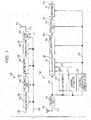
- FIG. 1 illustrates an example of a configuration of a system which includes transmission device 100 and reception device 150, and which uses radio waves. Note that FIG. 1 illustrates the system which uses radio waves. However, the system is not limited to this, and may be a system which uses cables (coaxial cables, cables, light or the like).
- Encoder 103 receives an input of information 101 and control information 102, performs error correction coding based on information of a code included in control information 102 and used for the error correction coding by a transmission device, such as information of a coding rate and a code length (block length), and outputs data 104 obtained after the error correction coding.
- Puncturing unit 105 receives an input of control information 102 and data 104 obtained after the error correction coding, determines whether or not to puncture data 104 obtained after the error correction coding (whether or not to delete part of a bit sequence) based on the information of the code included in control information 102 and used for the error correction coding by the transmission device such as information of a coding rate and a code length (block length), and outputs data 106.
- Interleaver 107 receives an input of control information 102 and data 106, rearranges data based on information included in control information 102 and related to an interleaving method, and outputs rearranged data 108.
- Mapper 109 receives an input of control information 102 and rearranged data 108, performs mapping based on information included in control information 102 and related to a modulation method, and outputs baseband signal 110.
- Radio unit 112 receives an input of control information 102, baseband signal 110 and pilot signal 111. Radio unit 112 performs processing such as inserting a control information symbol demodulated from control information 102 by a receiver (including information related to a modulation method, an error correction coding method or the like), a pilot symbol and the like into a data symbol, and generates a frame.
- processing such as inserting a control information symbol demodulated from control information 102 by a receiver (including information related to a modulation method, an error correction coding method or the like), a pilot symbol and the like into a data symbol, and generates a frame.
- radio unit 112 performs signal processing based on control information 102 (for example, radio unit 112 performs signal processing based on OFDM (Orthogonal Frequency Division Multiplexing) when OFDM is used, or performs signal processing based on an MIMO (Multiple Input-Multiple-Output) method when the MIMO method is used, or performs processing such as frequency conversion, band limitation and amplification), and outputs transmission signal 113.
- Transmission signal 113 is output as a radio wave from antenna 114 (note that a number of antennas described herein is two, but is not limited to this).
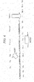
- FIG. 1 illustrates an example of a configuration of reception device 150 which receives a modulated signal transmitted by transmission device 100.
- Radio unit 153 performs processing such as frequency conversion on received signal 152 received at antenna 151, and outputs baseband signal 154.
- Synchronizer 155 receives an input of baseband signal 154, performs processing for frequency synchronization and time synchronization by using a pilot symbol, a preamble and the like included in a baseband signal, and outputs synchronization signal 156.
- Channel estimator 157 receives an input of baseband signal 154, performs channel estimation by using a pilot symbol, a preamble and the like included in a baseband signal, and outputs channel estimation signal 15.
- Control information demodulator 159 receives an input of baseband signal 154, demodulates a control information symbol included in the baseband signal, and outputs control information signal 160.
- Demodulator 161 receives an input of baseband signal 154, synchronization signal 156, channel estimation signal 158 and control information signal 160, calculates, for example, a log likelihood ratio of each bit of a data symbol included in baseband signal 154 by using synchronization signal 156 and channel estimation signal 158 based on information included in control information signal 160 and related to a transmission method such as a modulation method, and outputs log likelihood ratio signal 162.
- Deinterleaver 163 receives an input of control information signal 160 and log likelihood ratio signal 162, rearranges an order of log likelihood ratios based on information included in control information signal 160 and related to an interleaving method, and outputs rearranged log likelihood ratio signal 164.
- Insertion unit 165 receives an input of control information signal 160, and determines whether the transmission device has performed puncturing or has not performed the puncturing (whether the transmission device has deleted part of a bit sequence or has not deleted part of the bit sequence) based on information of a block length (code length) and a coding rate of an error correction code in control information signal 160.
- insertion unit 165 inserts into rearranged log likelihood ratio signal 164 a log likelihood ratio (for example, a value of "0") corresponding to a bit punctured (deleted) by the transmission device.
- a log likelihood ratio for example, a value of "0
- insertion unit 165 When it is determined that the "transmission device has not performed the puncturing," insertion unit 165 does not insert the above-described log likelihood ratio.
- insertion unit 165 outputs second log likelihood ratio signal 166.
- Decoder 167 receives an input of control information signal 160 and second log likelihood ratio signal 166, performs error correction decoding based on information included in the control information signal and related to an error correction code, and outputs received data 168.
- BP belief propagation
- FIG. 2 illustrates a configuration of the encoder.
- coding rate R m/(m + n) holds.
- (p 1 , p 2 , ..., p n ) will be referred to as a parity sequence.
- the transmission device transmits a total of m + n bits of (x 1 , x 2 , ..., x m , p 1 , p 2 , ..., p n ) as one encoded block.
- a number of rows of parity check matrix H is n, and a number of columns is m + n.
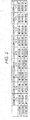
- FIG. 3 illustrates a specific example of the LDPC code using puncturing.
- the transmission device selects a total of y bits of "x 3 , ..., x m-2 , p 1 , ..., p n-1 ,” determines not to transmit these y bits, and transmits sequence z 1 , z 2 , z 3 , ..., z m + n - y + 2 , z m + n - y + 1 , z m + n - y of a total of the m + n - y bits other than the bits determined not to be transmitted.
- the y bits not to be transmitted are selected from both of an information sequence and a parity sequence, but are not limited to this and may be selected only from an information sequence or may be selected only from a parity sequence. That is, the y bits not to be transmitted may be selected from an encoded sequence in any way.
- the transmission device transmits a total of the m + n - y bits of (z 1 , z 2 , z 3 , ... , z m + n - y + 2 , z m + n - y + 1 , z m + n - y ) as one encoded block.
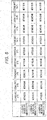
- FIG. 4 illustrates an example of an operation example of the reception device when the transmission device transmits data as illustrated in FIG. 3 .
- the reception device receives sequence z 1 , z 2 , z 3 , ..., z m + n - y + 2 , z m + n - y + 1 , z m + n - y , and sets log likelihood ratios of these bits to Lz 1 , Lz 2 , Lz 3 , ..., Lz m + n - y + 2 , Lz m + n - y + 1 , Lz m + n - y .
- log likelihood ratios Lx 1 , Lx 2 , Lx 3 , ..., Lx m - 2 , Lx m - 1 , Lx m , Lp 1 , Lp 2 , Lp 3 , ..., Lp n - 2 , Lp n - 1 , Lp n of bits of x 1 , x 2 , x 3 , ..., x m - 2 , x m - 1 , x m , p 1 , p 2 , p 3 , ..., p n - 2 , P n - 1 , p n are obtained.
- the reception device performs BP decoding by using Lx 1 , Lx 2 , Lx 3 , ..., Lx m - 2 , Lx m - 1 , Lx m , Lp 1 , Lp 2 , Lp 3 , ..., Lp n - 2 , Lp n - 1 , Lp n , and obtains received data.
- data reception quality depends on specific values of ⁇ and ⁇ . (Moreover, the values of ⁇ and ⁇ are likely to change depending on a coding rate.) A specific example will be described below.
- FIG. 5 is an example illustrating which one of "method #A" and “method #B” is used for number of bits z and a coding rate of one encoded block.
- a coding rate means a coding rate obtained after puncturing (after bits not to be transmitted are deleted) instead of a coding rate of the LDPC code.
- Condition 5-1 An LDPC code that is a base of "method #A in a case of coding rate a" and an LDPC code that is a base of "method #A in a case of coding rate b" are different codes.
- Condition 5-2 A parity check matrix of an LDPC code that is a base of "method #A in a case of coding rate a" and a parity check matrix of an LDPC code that is a base of "method #A in a case of coding rate b" are different.
- Condition 5-3 A number of rows of a parity check matrix of an LDPC code that is a base of "method #A in a case of coding rate a" and a number of rows of a parity check matrix of an LDPC code that is a base of "method #A in a case of coding rate b" are different.
- Condition 5-4 A number of columns of a parity check matrix of an LDPC code that is a base of "method #A in a case of coding rate a" and a number of columns of a parity check matrix of an LDPC code that is a base of "method #A in a case of coding rate b" are different.
- a number of bits of one encoded block is z bits. Note that z is a natural number.
- the z bits of one encoded block are realized by using an "LDPC coding method using puncturing.” Note that this method will be referred to as “method #A.”
- the z bits of one encoded block are realized by using an "LDPC coding method which does not perform puncturing.” Note that this method will be referred to as “method #B.”
- the transmission device and the reception device set a coding rate from coding rates illustrated in FIG. 6 , and also select one encoded block from the number of bits of one encoded block illustrated in FIG. 6 .
- FIG. 6 is an example illustrating which one of "method #A" and “method #B” is used for number of bits z and a coding rate of one encoded block.
- a coding rate means a coding rate obtained after puncturing (after bits not to be transmitted are deleted) instead of a coding rate of the LDPC code.
- Condition 6-1 An LDPC code that is a base of "method #A in a case of coding rate a" and an LDPC code that is a base of "method #A in a case of coding rate b" are different codes.
- Condition 6-2 A parity check matrix of an LDPC code that is a base of "method #A in a case of coding rate a" and a parity check matrix of an LDPC code that is a base of "method #A in a case of coding rate b" are different.
- Condition 6-3 A number of rows of a parity check matrix of an LDPC code that is a base of "method #A in a case of coding rate a" and a number of rows of a parity check matrix of an LDPC code that is a base of "method #A in a case of coding rate b" are different.
- Condition 6-4 A number of columns of a parity check matrix of an LDPC code that is a base of "method #A in a case of coding rate a" and a number of columns of a parity check matrix of an LDPC code that is a base of "method #A in a case of coding rate b" are different.
- a number of bits of one encoded block is z bits. Note that z is a natural number.
- the z bits of one encoded block are realized by using an "LDPC coding method using puncturing.” Note that this method will be referred to as “method #A.”
- the z bits of one encoded block are realized by using an "LDPC coding method which does not perform puncturing.” Note that this method will be referred to as “method #B.”
- the transmission device and the reception device set a coding rate from coding rates illustrated in FIG. 7 , and also select one encoded block from the number of bits of one encoded block illustrated in FIG. 7 .
- FIG. 7 is an example illustrating which one of "method #A" and “method #B” is used for number of bits z and a coding rate of one encoded block.
- a coding rate means a coding rate obtained after puncturing (after bits not to be transmitted are deleted) instead of a coding rate of the LDPC code.
- Condition 7-1 An LDPC code that is a base of "method #A in a case of coding rate a" and an LDPC code that is a base of "method #A in a case of coding rate b" are different codes.
- Condition 7-2 A parity check matrix of an LDPC code that is a base of "method #A in a case of coding rate a" and a parity check matrix of an LDPC code that is a base of "method #A in a case of coding rate b" are different.
- Condition 7-3 A number of rows of a parity check matrix of an LDPC code that is a base of "method #A in a case of coding rate a" and a number of rows of a parity check matrix of an LDPC code that is a base of "method #A in a case of coding rate b" are different.
- Condition 7-4 A number of columns of a parity check matrix of an LDPC code that is a base of "method #A in a case of coding rate a" and a number of columns of a parity check matrix of an LDPC code that is a base of "method #A in a case of coding rate b" are different.
- a number of bits of one encoded block is z bits. Note that z is a natural number.
- the z bits of one encoded block are realized by using an "LDPC coding method using puncturing.” Note that this method will be referred to as “method #A.”
- the z bits of one encoded block are realized by using an "LDPC coding method which does not perform puncturing.” Note that this method will be referred to as “method #B.”
- the transmission device and the reception device set a coding rate from coding rates illustrated in FIG. 8 , and also select one encoded block from the number of bits of one encoded block illustrated in FIG. 8 .
- FIG. 8 is an example illustrating which one of "method #A" and “method #B” is used for number of bits z and a coding rate of one encoded block.
- a coding rate means a coding rate obtained after puncturing (after bits not to be transmitted are deleted) instead of a coding rate of the LDPC code.
- Condition 8-1 An LDPC code that is a base of "method #A in a case of coding rate a" and an LDPC code that is a base of "method #A in a case of coding rate b" are different codes.
- Condition 8-2 A parity check matrix of an LDPC code that is a base of "method #A in a case of coding rate a" and a parity check matrix of an LDPC code that is a base of "method #A in a case of coding rate b" are different.
- Condition 8-3 A number of rows of a parity check matrix of an LDPC code that is a base of "method #A in a case of coding rate a" and a number of rows of a parity check matrix of an LDPC code that is a base of "method #A in a case of coding rate b" are different.
- Condition 8-4 A number of columns of a parity check matrix of an LDPC code that is a base of "method #A in a case of coding rate a" and a number of columns of a parity check matrix of an LDPC code that is a base of "method #A in a case of coding rate b" are different.
- a number of bits of one encoded block is z bits. Note that z is a natural number.
- the z bits of one encoded block are realized by using an "LDPC coding method using puncturing.” Note that this method will be referred to as “method #A.”
- the z bits of one encoded block are realized by using an "LDPC coding method which does not perform puncturing.” Note that this method will be referred to as “method #B.”
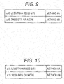
- the transmission device and the reception device select one encoded block from the number of bits of one encoded block illustrated in FIG. 9 . Note that a coding rate can also be set.
- FIG. 9 is an example illustrating which one of "method #A" and “method #B” is used for number of bits z of one encoded block.
- a coding rate means a coding rate obtained after puncturing (after bits not to be transmitted are deleted) instead of a coding rate of the LDPC code.
- Condition 9-1 An LDPC code that is a base of "method #A in a case of coding rate a" and an LDPC code that is a base of "method #A in a case of coding rate b" are different codes.
- Condition 9-2 A parity check matrix of an LDPC code that is a base of "method #A in a case of coding rate a" and a parity check matrix of an LDPC code that is a base of "method #A in a case of coding rate b" are different.
- Condition 9-3 A number of rows of a parity check matrix of an LDPC code that is a base of "method #A in a case of coding rate a" and a number of rows of a parity check matrix of an LDPC code that is a base of "method #A in a case of coding rate b" are different.
- Condition 9-4 A number of columns of a parity check matrix of an LDPC code that is a base of "method #A in a case of coding rate a" and a number of columns of a parity check matrix of an LDPC code that is a base of "method #A in a case of coding rate b" are different.
- a number of bits of one encoded block is z bits. Note that z is a natural number.
- the z bits of one encoded block are realized by using an "LDPC coding method using puncturing.” Note that this method will be referred to as “method #A.”
- the z bits of one encoded block are realized by using an "LDPC coding method which does not perform puncturing.” Note that this method will be referred to as “method #B.”
- the transmission device and the reception device select one encoded block from the number of bits of one encoded block illustrated in FIG. 10 . Note that a coding rate can also be set.
- FIG. 10 is an example illustrating which one of "method #A" and “method #B” is used for number of bits z of one encoded block.
- a coding rate means a coding rate obtained after puncturing (after bits not to be transmitted are deleted) instead of a coding rate of the LDPC code.
- Condition 10-1 An LDPC code that is a base of "method #A in a case of coding rate a" and an LDPC code that is a base of "method #A in a case of coding rate b" are different codes.
- Condition 10-2 A parity check matrix of an LDPC code that is a base of "method #A in a case of coding rate a" and a parity check matrix of an LDPC code that is a base of "method #A in a case of coding rate b" are different.
- Condition 10-3 A number of rows of a parity check matrix of an LDPC code that is a base of "method #A in a case of coding rate a" and a number of rows of a parity check matrix of an LDPC code that is a base of "method #A in a case of coding rate b" are different.
- Condition 10-4 A number of columns of a parity check matrix of an LDPC code that is a base of "method #A in a case of coding rate a" and a number of columns of a parity check matrix of an LDPC code that is a base of "method #A in a case of coding rate b" are different.
- FIG. 11 is an example of a configuration of a frame transmitted by the transmission device, and in FIG. 11 a horizontal axis is time.
- FIG. 11 is an example where a transmission method which uses, for example, a single carrier is used.
- a multi-carrier method such as OFDM (Orthogonal Frequency Division Multiplexing)
- OFDM Orthogonal Frequency Division Multiplexing
- a space-time code or an MIMO (Multiple Input-Multiple-Output) method there is a frame per stream.
- preamble 1101 uses, for example, a PSK (Phase Shift Keying) modulated symbol which is known in a transmitter and a receiver.
- the receiver performs frequency offset estimation, frequency synchronization, time synchronization, frame synchronization, channel estimation, signal detection and the like by using this symbol.
- PSK Phase Shift Keying
- Control information symbol 1102 includes, for example, information of an error correction code method (a code length, a block length of one encoded block, and a coding rate of one encoded block) used for generating a data symbol, information of a modulation method used for generating a data symbol, and information related to the transmission method.
- the reception device obtains the control information by demodulating this symbol, and, consequently, demodulation and error correction decoding of the data symbol become possible.
- Data symbol 1103 is generated based on an error correction coding method (a code length, a block length of one encoded block, and a coding rate of one encoded block), a modulation method and a transmission method selected by the transmission device. Note that although not illustrated in FIG. 11 , a symbol such as a pilot symbol may be inserted into symbols described as control information symbol 1102 and data symbol 1103.
- a frame configuration is not limited to the configuration in FIG. 11 .
- the transmission device can select a value of one encoded block of data to be transmitted from a plurality of values and provides a threshold.
- the transmission device selects the "LDPC coding method which does not perform puncturing" and transmits data.
- the transmission device selects the "LDPC coding method using puncturing” and transmits data. Consequently, the reception device can obtain an effect of obtaining high data reception quality at any value of one encoded block.
- a coding rate in a case of the "LDPC coding method using puncturing” means a coding rate obtained after puncturing (after bits not to be transmitted are deleted).
- Performance of an LDPC code of a low coding rate tends to have an expanding difference from Shannon limits.
- a small (low) coding rate such as coding rate ⁇ and in a case of "method $1”
- a coding rate of a base LDPC code is smaller than ⁇ . For this reason, the difference from Shannon limits is large and, when puncturing is performed, it is difficult to obtain good data reception quality.
- data reception quality depends on specific values of ⁇ , ⁇ and ⁇ . (Moreover, the values of ⁇ , ⁇ and ⁇ are likely to change depending on a value of one encoded block.) A specific example will be described below.
- a number of bits of one encoded block is z bits. Note that z is a natural number.
- the z bits of one encoded block are realized by using an "LDPC coding method using puncturing.” Note that this method will be referred to as “method #A.”
- the z bits of one encoded block are realized by using an "LDPC coding method which does not perform puncturing.” Note that this method will be referred to as “method #B.”
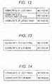
- the transmission device and the reception device select a coding rate from coding rates illustrated in FIG. 12 . Note that the number of bits of one encoded block can also be set.
- FIG. 12 is an example illustrating which one of "method #A" and “method #B” is used when number of bits z of one encoded block is set to a certain value.
- a coding rate means a coding rate obtained after puncturing (after bits not to be transmitted are deleted) instead of a coding rate of the LDPC code.
- e and f are larger than 0 and smaller than 1, and e ⁇ f holds.
- any of coding rate a and coding rate b is a coding rate obtained after puncturing (after bits not to be transmitted are deleted).
- a ⁇ b holds.
- Condition 12-1 An LDPC code that is a base of "method #A in a case of coding rate a" and an LDPC code that is a base of "method #A in a case of coding rate b" are different codes.
- Condition 12-2 A parity check matrix of an LDPC code that is a base of "method #A in a case of coding rate a" and a parity check matrix of an LDPC code that is a base of "method #A in a case of coding rate b" are different.
- Condition 12-3 A number of rows of a parity check matrix of an LDPC code that is a base of "method #A in a case of coding rate a" and a number of rows of a parity check matrix of an LDPC code that is a base of "method #A in a case of coding rate b" are different.
- Condition 12-4 A number of columns of a parity check matrix of an LDPC code that is a base of "method #A in a case of coding rate a" and a number of columns of a parity check matrix of an LDPC code that is a base of "method #A in a case of coding rate b" are different.
- a number of bits of one encoded block is z bits. Note that z is a natural number.
- the z bits of one encoded block are realized by using an "LDPC coding method using puncturing.” Note that this method will be referred to as “method #A.”
- the z bits of one encoded block are realized by using an "LDPC coding method which does not perform puncturing.” Note that this method will be referred to as “method #B.”
- the transmission device and the reception device select a coding rate from coding rates illustrated in FIG. 13 . Note that the number of bits of one encoded block can also be set.
- FIG. 13 is an example illustrating which one of "method #A" and "method #B" is used for number of bits z of one encoded block.
- a coding rate means a coding rate obtained after puncturing (after bits not to be transmitted are deleted) instead of a coding rate of the LDPC code.
- g is larger than 0 and is smaller than 1.
- the transmission device can select "method #A in a case of coding rate a" and "method #A in a case of coding rate b.”
- any of coding rate a and coding rate b is a coding rate obtained after puncturing (after bits not to be transmitted are deleted).
- a ⁇ b holds.
- Condition 13-1 An LDPC code that is a base of "method #A in a case of coding rate a" and an LDPC code that is a base of "method #A in a case of coding rate b" are different codes.
- Condition 13-2 A parity check matrix of an LDPC code that is a base of "method #A in a case of coding rate a" and a parity check matrix of an LDPC code that is a base of "method #A in a case of coding rate b" are different.
- Condition 13-3 A number of rows of a parity check matrix of an LDPC code that is a base of "method #A in a case of coding rate a" and a number of rows of a parity check matrix of an LDPC code that is a base of "method #A in a case of coding rate b" are different.
- Condition 13-4 A number of columns of a parity check matrix of an LDPC code that is a base of "method #A in a case of coding rate a" and a number of columns of a parity check matrix of an LDPC code that is a base of "method #A in a case of coding rate b" are different.
- a number of bits of one encoded block is z bits. Note that z is a natural number.
- the z bits of one encoded block are realized by using an "LDPC coding method using puncturing.” Note that this method will be referred to as “method #A.”
- the z bits of one encoded block are realized by using an "LDPC coding method which does not perform puncturing.” Note that this method will be referred to as “method #B.”
- the transmission device and the reception device select a coding rate from coding rates illustrated in FIG. 14 . Note that the number of bits of one encoded block can also be set.
- FIG. 14 is an example illustrating which one of "method #A" and "method #B" is used for number of bits z of one encoded block.
- a coding rate means a coding rate obtained after puncturing (after bits not to be transmitted are deleted) instead of a coding rate of the LDPC code.
- h is larger than 0 and is smaller than 1.
- any of coding rate a and coding rate b is a coding rate obtained after puncturing (after bits not to be transmitted are deleted).
- a ⁇ b holds.
- Condition 14-1 An LDPC code that is a base of "method #A in a case of coding rate a" and an LDPC code that is a base of "method #A in a case of coding rate b" are different codes.
- Condition 14-2 A parity check matrix of an LDPC code that is a base of "method #A in a case of coding rate a" and a parity check matrix of an LDPC code that is a base of "method #A in a case of coding rate b" are different.
- Condition 14-3 A number of rows of a parity check matrix of an LDPC code that is a base of "method #A in a case of coding rate a" and a number of rows of a parity check matrix of an LDPC code that is a base of "method #A in a case of coding rate b" are different.
- Condition 14-4 A number of columns of a parity check matrix of an LDPC code that is a base of "method #A in a case of coding rate a" and a number of columns of a parity check matrix of an LDPC code that is a base of "method #A in a case of coding rate b" are different.
- coding rates there may be two or more types of coding rates which are less than h, and one or more types of coding rates which are h or more.
- the transmission device sets to a predetermined value a value of one encoded block of data to be transmitted, and provides a threshold.
- the transmission device selects the "LDPC coding method which does not perform puncturing" when the coding rate is the threshold or more, and selects the "LDPC coding method using puncturing” when the coding rate is less than the threshold.
- the transmission device selects the "LDPC coding method using puncturing” when the coding rate is the threshold or more, and selects the "LDPC coding method which does not perform puncturing" when the coding rate is less than the threshold. Consequently, the reception device can obtain an effect of obtaining higher data reception quality at any coding rate.
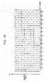
- FIG. 15 illustrates an example of parameters of an error correction code according to the present exemplary embodiment.
- a number of bits of one encoded block is z bits. Note that z is a natural number.
- the z bits of one encoded block are realized by using an "LDPC coding method using puncturing.” This method will be referred to as “method #A.”
- the z bits of one encoded block are realized by using an "LDPC coding method which does not perform puncturing.” This method will be referred to as “method #B.”
- LDPC coding method using puncturing coding is performed on an LDPC code (LDPC block code) with a code length (block length) of z + ⁇ bits ( ⁇ is a natural number), and data of the z + ⁇ bits is obtained. Then, the ⁇ bits are punctured (the ⁇ bits not to be transmitted are determined), and data of the z bits to be transmitted is obtained.
- the "z bits of one encoded block” means that "this data to be transmitted is of the z bits.”
- LDPC coding method which does not perform puncturing
- coding is performed on an LDPC code (LDPC block code) with a code length of z bits, and data of the z bits is obtained and transmitted.
- LDPC code LDPC block code
- the "z bits of one encoded block” means that "this data to be transmitted is of the z bits.”
- FIG. 15 is an example illustrating which one of "method #A" and “method #B” is used for number of bits z and a coding rate of one encoded block.
- a coding rate means a coding rate obtained after puncturing (after bits not to be transmitted are deleted) instead of a coding rate of the LDPC code (instead of a coding rate obtained before puncturing).
- FIG. 15 is such that the "transmission device and the reception device support number of bits x (x is a natural number) of one encoded block and number of bits y (y is a natural number) of one encoded block.
- FIG. 15 may be interpreted such that "number of bits x (x is a natural number) of one encoded block and number of bits y (y is a natural number) of one encoded block are supported at a certain coding rate.
- “method #B” is used in a case of number of bits x of one encoded block
- “method #A” is used in a case of number of bits y of one encoded block” (however, at another coding rate, "method #B” may be used for both of number of bits x of one encoded block and number of bits y of one encoded block).
- FIG. 16 is an example different from FIG. 15 and illustrating which one of "method #A" and “method #B” is used for number of bits z and a coding rate of one encoded block.
- a coding rate means a coding rate obtained after puncturing (after bits not to be transmitted are deleted) instead of a coding rate of the LDPC code (instead of a coding rate obtained before puncturing).
- features of FIG. 16 are such that "number of bits x (x is a natural number) of one encoded block and number of bits y (y is a natural number) of one encoded block are supported at a certain coding rate.
- “method #B” is used in a case of number of bits x of one encoded block
- “method #A” is used in a case of number of bits y of one encoded block” (however, at another coding rate, “method #B” may be used for both of number of bits x of one encoded block and number of bits y of one encoded block).
- FIG. 17 illustrates an example of a configuration of the transmission device, and the same operations as those in FIG. 1 will be assigned the same reference numerals and will not be described.
- Encoder 103 in FIG. 17 receives an input of information 101 and control information 102, and performs error correction processing based on FIG. 15 or 16 .
- Control information 102 includes information of number of bits z of one encoded block of an error correction code (LDPC code), and information of a coding rate used for error correction coding (a coding rate obtained after puncturing when puncturing is performed).
- LDPC code error correction code
- a coding rate used for error correction coding means a coding rate obtained after puncturing (after bits not to be transmitted are deleted) instead of a coding rate of the LDPC code (instead of a coding rate obtained before puncturing).
- the coding rate used for error correction coding means a coding rate of an LDPC code.
- encoder 103 receives an input of information 101 and control information 102.
- Encoder 103 performs error correction coding (including puncturing processing) on information 101 based on the information of number of bits z of one encoded block of the error correction code (LDPC code) included in control information 102, and the information of the coding rate used for the error correction coding included in control information 102.
- Encoder 103 outputs data 104 obtained after the error correction coding.
- encoder 101 performs encoding in "method #A" corresponding to the coding rate 5/15 (as described above, encoder 101 performs encoding of an LDPC code, and performs puncturing (encoder 101 selects bits not to be transmitted and determines data to be transmitted)).
- encoder 101 performs encoding in "method #A" corresponding to the coding rate 6/15 (as described above, encoder 101 performs encoding of an LDPC code, and performs puncturing (encoder 101 selects bits not to be transmitted and determines data to be transmitted)).
- encoder 101 performs encoding in "method #A" corresponding to the coding rate 7/15 (as described above, encoder 101 performs encoding of an LDPC code, and performs puncturing (encoder 101 selects bits not to be transmitted and determines data to be transmitted)).
- encoder 101 performs encoding in "method #A" corresponding to the coding rate 8/15 (as described above, encoder 101 performs encoding of an LDPC code, and performs puncturing (encoder 101 selects bits not to be transmitted and determines data to be transmitted)).
- encoder 101 performs encoding in "method #B" corresponding to the coding rate 9/15 (encoder 101 does not perform puncturing as described above).
- encoder 101 performs encoding in "method #B" corresponding to the coding rate 10/15 (encoder 101 does not perform puncturing as described above).
- encoder 101 performs encoding in "method #B" corresponding to the coding rate 11/15 (encoder 101 does not perform puncturing as described above).
- encoder 101 performs encoding in "method #B" corresponding to the coding rate 12/15 (encoder 101 does not perform puncturing as described above).
- encoder 101 performs encoding in "method #B" corresponding to the coding rate 13/15 (encoder 101 does not perform puncturing as described above).
- encoder 101 performs encoding in "method #B" corresponding to the coding rate 5/15 (encoder 101 does not perform puncturing as described above).
- encoder 101 performs encoding in "method #B" corresponding to the coding rate 6/15 (encoder 101 does not perform puncturing as described above).
- encoder 101 performs encoding in "method #B" corresponding to the coding rate 7/15 (encoder 101 does not perform puncturing as described above).
- encoder 101 performs encoding in "method #B" corresponding to the coding rate 8/15 (encoder 101 does not perform puncturing as described above).
- encoder 101 performs encoding in "method #B" corresponding to the coding rate 9/15 (encoder 101 does not perform puncturing as described above).
- encoder 101 performs encoding in "method #B" corresponding to the coding rate 10/15 (encoder 101 does not perform puncturing as described above).
- encoder 101 performs encoding in "method #B" corresponding to the coding rate 11/15 (encoder 101 does not perform puncturing as described above).
- encoder 101 performs encoding in "method #B" corresponding to the coding rate 12/15 (encoder 101 does not perform puncturing as described above).
- encoder 101 performs encoding in "method #B" corresponding to the coding rate 13/15 (encoder 101 does not perform puncturing as described above).
- encoder 103 receives an input of information 101 and control information 102.
- Encoder 103 performs error correction coding (including puncturing processing) on information 101 based on the information of number of bits z of one encoded block of the error correction code (LDPC code) included in control information 102, and the information of the coding rate used for the error correction coding included in control information 102.
- Encoder 103 outputs data 104 obtained after the error correction coding.
- encoder 101 performs encoding in "method #A" corresponding to the coding rate 5/15 (as described above, encoder 101 performs encoding of an LDPC code, and performs puncturing (encoder 101 selects bits not to be transmitted and determines data to be transmitted)).
- encoder 101 performs encoding in "method #A" corresponding to the coding rate 6/15 (as described above, encoder 101 performs encoding of an LDPC code, and performs puncturing (encoder 101 selects bits not to be transmitted and determines data to be transmitted)).
- encoder 101 performs encoding in "method #A" corresponding to the coding rate 7/15 (as described above, encoder 101 performs encoding of an LDPC code, and performs puncturing (encoder 101 selects bits not to be transmitted and determines data to be transmitted)).
- encoder 101 performs encoding in "method #B" corresponding to the coding rate 8/15 (encoder 101 does not perform puncturing as described above).
- encoder 101 performs encoding in "method #B" corresponding to the coding rate 9/15 (encoder 101 does not perform puncturing as described above).
- encoder 101 performs encoding in "method #B" corresponding to the coding rate 10/15 (encoder 101 does not perform puncturing as described above).
- encoder 101 performs encoding in "method #B" corresponding to the coding rate 11/15 (encoder 101 does not perform puncturing as described above).
- encoder 101 performs encoding in "method #B" corresponding to the coding rate 12/15 (encoder 101 does not perform puncturing as described above).
- encoder 101 performs encoding in "method #B" corresponding to the coding rate 13/15 (encoder 101 does not perform puncturing as described above).
- encoder 101 performs encoding in "method #B" corresponding to the coding rate 5/15 (encoder 101 does not perform puncturing as described above).
- encoder 101 performs encoding in "method #B" corresponding to the coding rate 6/15 (encoder 101 does not perform puncturing as described above).
- encoder 101 performs encoding in "method #B" corresponding to the coding rate 7/15 (encoder 101 does not perform puncturing as described above).
- encoder 101 performs encoding in "method #B" corresponding to the coding rate 8/15 (encoder 101 does not perform puncturing as described above).
- encoder 101 performs encoding in "method #B" corresponding to the coding rate 9/15 (encoder 101 does not perform puncturing as described above).
- encoder 101 performs encoding in "method #B" corresponding to the coding rate 10/15 (encoder 101 does not perform puncturing as described above).
- encoder 101 performs encoding in "method #B" corresponding to the coding rate 11/15 (encoder 101 does not perform puncturing as described above).
- encoder 101 performs encoding in "method #B" corresponding to the coding rate 12/15 (encoder 101 does not perform puncturing as described above).
- encoder 101 performs encoding in "method #B" corresponding to the coding rate 13/15 (encoder 101 does not perform puncturing as described above).
- Encoded block bit number information generator 1701 receives an input of control information 102. Encoded block bit number information generator 1701 extracts information of number of bits z of one encoded block of an error correction code (LDPC code) included in control information 102. Encoded block bit number information generator 1701 outputs information 1702 of the number of bits of one encoded block for forming a control information symbol.
- LDPC code error correction code
- Coding rate information generator 1703 receives an input of control information 102. Coding rate information generator 1703 extracts information of a coding rate used for error correction coding included in control information 102 (a coding rate obtained after puncturing when puncturing is performed). Coding rate information generator 1703 outputs information 1704 of the coding rate used for the error correction coding for forming the control information symbol.
- Other control information generator 1705 receives an input of control information 102.
- Other control information generator 1705 outputs control information 1706 for forming a control information symbol other than information of the number of bits of one encoded block for forming a control information symbol and information of a coding rate used for error correction coding for forming a control information symbol.
- Control information symbol generator 1707 receives an input of information 1702 of the number of bits of one encoded block, information 1704 of a coding rate used for error correction coding, and control information 1706. Control information symbol generator 1707 performs processing such as error correction coding and mapping, and outputs control information symbol baseband signal 1708.
- Radio unit 112 receives an input of control information 102, baseband signal 110, pilot signal 111 and control information symbol baseband signal 1708. Based on information related to a frame configuration included in control information 102, radio unit 112 generates and outputs transmission signal 113 which is based on a frame configuration (radio unit 112 performs processing such as inverse Fourier transform and frequency conversion in a case of, for example, using OFDM (Orthogonal Frequency Division Multiplexing)).
- processing such as inverse Fourier transform and frequency conversion in a case of, for example, using OFDM (Orthogonal Frequency Division Multiplexing)).
- FIG. 18 illustrates an example of a frame configuration of a modulated signal transmitted by the transmission device in FIG. 17 (an example of a frame configuration in a case of transmitting one modulated signal).
- a vertical axis indicates time
- a horizontal axis indicates a frequency.
- OFDM Orthogonal Frequency Division Multiplexing
- control information symbol includes information of the number of bits of one encoded block and information of a coding rate used for error correction coding.
- the pilot symbol is a symbol for channel estimation (propagation channel fluctuation estimation), frequency synchronization, time synchronization, signal detection, frequency offset estimation and the like performed by the reception device which receives a modulated signal transmitted by the transmission device.
- the pilot symbol only needs to be a symbol modulated by using PSK (Phase Shift Keying) modulation and known in a transmitter and a receiver (or a receiver may be capable of learning a symbol transmitted by the transmitter by establishing synchronization).
- PSK Phase Shift Keying
- the data symbol is a symbol for transmitting data generated based on, for example, FIG. 15 or 16 and obtained after error correction coding (note that the number of bits of one encoded block of data obtained after error correction coding, and the coding rate used for error correction coding are a number of bits of one encoded block and a coding rate used for error correction coding which are specified by information of the number of bits of one encoded block and information of a coding rate used for error correction coding included in a control information symbol).
- a confguration of the reception device which receives a modulated signal transmitted by the transmission device in FIG. 17 is as indicated by 150 in FIG. 1 .
- Operations of control information demodulator 159 and decoder 167 in reception device 150 in FIG. 1 in particular will be described in detail below.
- FIG. 19 is a view illustrating a configuration of a portion related to control information demodulator 159 and decoder 167 in reception device 150 in FIG. 1 .
- Control information demodulator 159 includes one encoded block bit number information/coding rate information estimator 1903.
- One encoded block bit number information/coding rate information estimator 1903 receives an input of baseband signal 1902, and extracts the control information symbol illustrated in FIG. 18 . Further, one encoded block bit number information/coding rate information estimator 1903 obtains information of the number of bits of one encoded block and information of a coding rate used for error correction coding, from the control information symbol.
- One encoded block bit number information/coding rate information estimator 1903 outputs estimation signal 1904 of the information of the number of bits of one encoded block and the information of the coding rate used for error correction coding.
- Puncture bit log likelihood ratio generator 1905 receives an input of estimation signal 1904 of the information of the number of bits of one encoded block and the information of the coding rate used for error correction coding. Puncture bit log likelihood ratio generator 1905 determines whether a method used by the transmission device to generate data of a data symbol is "method #A" or "method #B" described with reference to FIGS. 15 and 16 , from the information of the number of bits of one encoded block and the information of the coding rate used for error correction coding based on FIG. 15 or 16 . When it is determined that the method is "method #B,” puncture bit log likelihood ratio generator 1905 generates and outputs log likelihood ratio 106 of bits corresponding to bits (bits which are not transmitted by the transmission device) punctured by the transmission device.
- puncture bit log likelihood ratio generator 1905 determines as follows.
- puncture bit log likelihood ratio generator 1905 determines that the method used by the transmission device to generate data of a data symbol is "method #A.”
- puncture bit log likelihood ratio generator 1905 determines that the method used by the transmission device to generate data of a data symbol is "method #A.”
- puncture bit log likelihood ratio generator 1905 determines that the method used by the transmission device to generate data of a data symbol is "method #A.”
- puncture bit log likelihood ratio generator 1905 determines that the method used by the transmission device to generate data of a data symbol is "method #A.”
- puncture bit log likelihood ratio generator 1905 determines that the method used by the transmission device to generate data of a data symbol is "method #B.”
- puncture bit log likelihood ratio generator 1905 determines that the method used by the transmission device to generate data of a data symbol is "method #B.”
- puncture bit log likelihood ratio generator 1905 determines that the method used by the transmission device to generate data of a data symbol is "method #B.”
- puncture bit log likelihood ratio generator 1905 determines that the method used by the transmission device to generate data of a data symbol is "method #B.”
- puncture bit log likelihood ratio generator 1905 determines that the method used by the transmission device to generate data of a data symbol is "method #B.”
- puncture bit log likelihood ratio generator 1905 determines that the method used by the transmission device to generate data of a data symbol is "method #B.”
- puncture bit log likelihood ratio generator 1905 determines that the method used by the transmission device to generate data of a data symbol is "method #B.”
- puncture bit log likelihood ratio generator 1905 determines that the method used by the transmission device to generate data of a data symbol is "method #B.”
- puncture bit log likelihood ratio generator 1905 determines that the method used by the transmission device to generate data of a data symbol is "method #B.”
- puncture bit log likelihood ratio generator 1905 determines that the method used by the transmission device to generate data of a data symbol is "method #B.”
- puncture bit log likelihood ratio generator 1905 determines that the method used by the transmission device to generate data of a data symbol is "method #B.”
- puncture bit log likelihood ratio generator 1905 determines as follows.
- estimation signal 1904 of the information of the number of bits of one encoded block and the information of the coding rate used for error correction coding indicates that the information of number of bits z of one encoded block of an error correction code (LDPC code) indicates "z being 10000 bits or more and 20000 bits or less," and that the information of the coding rate used for error correction coding indicates a coding rate 5/15
- LDPC code error correction code
- puncture bit log likelihood ratio generator 1905 determines that the method used by the transmission device to generate data of a data symbol is "method #A.”
- estimation signal 1904 of the information of the number of bits of one encoded block and the information of the coding rate used for error correction coding indicates that the information of number of bits z of one encoded block of an error correction code (LDPC code) indicates "z being 10000 bits or more and 20000 bits or less," and that the information of the coding rate used for error correction coding indicates a coding rate 6/15
- LDPC code error correction code
- puncture bit log likelihood ratio generator 1905 determines that the method used by the transmission device to generate data of a data symbol is "method #A.”
- estimation signal 1904 of the information of the number of bits of one encoded block and the information of the coding rate used for error correction coding indicates that the information of number of bits z of one encoded block of an error correction code (LDPC code) indicates "z being 10000 bits or more and 20000 bits or less," and that the information of the coding rate used for error correction coding indicates a coding rate 7/15
- LDPC code error correction code
- puncture bit log likelihood ratio generator 1905 determines that the method used by the transmission device to generate data of a data symbol is "method #A.”
- estimation signal 1904 of the information of the number of bits of one encoded block and the information of the coding rate used for error correction coding indicates that the information of number of bits z of one encoded block of an error correction code (LDPC code) indicates "z being 10000 bits or more and 20000 bits or less," and that the information of the coding rate used for error correction coding indicates a coding rate 8/15
- LDPC code error correction code
- puncture bit log likelihood ratio generator 1905 determines that the method used by the transmission device to generate data of a data symbol is "method #B.”
- estimation signal 1904 of the information of the number of bits of one encoded block and the information of the coding rate used for error correction coding indicates that the information of number of bits z of one encoded block of an error correction code (LDPC code) indicates "z being 10000 bits or more and 20000 bits or less," and that the information of the coding rate used for error correction coding indicates a coding rate 9/15
- LDPC code error correction code
- puncture bit log likelihood ratio generator 1905 determines that the method used by the transmission device to generate data of a data symbol is "method #B.”
- estimation signal 1904 of the information of the number of bits of one encoded block and the information of the coding rate used for error correction coding indicates that the information of number of bits z of one encoded block of an error correction code (LDPC code) indicates "z being 10000 bits or more and 20000 bits or less," and that the information of the coding rate used for error correction coding indicates a coding rate 10/15
- LDPC code error correction code
- puncture bit log likelihood ratio generator 1905 determines that the method used by the transmission device to generate data of a data symbol is "method #B.”
- estimation signal 1904 of the information of the number of bits of one encoded block and the information of the coding rate used for error correction coding indicates that the information of number of bits z of one encoded block of an error correction code (LDPC code) indicates "z being 10000 bits or more and 20000 bits or less," and that the information of the coding rate used for error correction coding indicates a coding rate 11/15
- LDPC code error correction code
- puncture bit log likelihood ratio generator 1905 determines that the method used by the transmission device to generate data of a data symbol is "method #B.”
- estimation signal 1904 of the information of the number of bits of one encoded block and the information of the coding rate used for error correction coding indicates that the information of number of bits z of one encoded block of an error correction code (LDPC code) indicates "z being 10000 bits or more and 20000 bits or less," and that the information of the coding rate used for error correction coding indicates a coding rate 12/15
- LDPC code error correction code
- puncture bit log likelihood ratio generator 1905 determines that the method used by the transmission device to generate data of a data symbol is "method #B.”
- estimation signal 1904 of the information of the number of bits of one encoded block and the information of the coding rate used for error correction coding indicates that the information of number of bits z of one encoded block of an error correction code (LDPC code) indicates "z being 10000 bits or more and 20000 bits or less," and that the information of the coding rate used for error correction coding indicates a coding rate 13/15
- LDPC code error correction code
- puncture bit log likelihood ratio generator 1905 determines that the method used by the transmission device to generate data of a data symbol is "method #B.”
- estimation signal 1904 of the information of the number of bits of one encoded block and the information of the coding rate used for error correction coding indicates that the information of number of bits z of one encoded block of an error correction code (LDPC code) indicates "z being 50000 bits or more and 70000 bits or less," and that the information of the coding rate used for error correction coding indicates a coding rate 5/15
- LDPC code error correction code
- puncture bit log likelihood ratio generator 1905 determines that the method used by the transmission device to generate data of a data symbol is "method #B.”
- estimation signal 1904 of the information of the number of bits of one encoded block and the information of the coding rate used for error correction coding indicates that the information of number of bits z of one encoded block of an error correction code (LDPC code) indicates "z being 50000 bits or more and 70000 bits or less," and that the information of the coding rate used for error correction coding indicates a coding rate 6/15
- LDPC code error correction code
- puncture bit log likelihood ratio generator 1905 determines that the method used by the transmission device to generate data of a data symbol is "method #B.”
- estimation signal 1904 of the information of the number of bits of one encoded block and the information of the coding rate used for error correction coding indicates that the information of number of bits z of one encoded block of an error correction code (LDPC code) indicates "z being 50000 bits or more and 70000 bits or less," and that the information of the coding rate used for error correction coding indicates a coding rate 7/15
- LDPC code error correction code
- puncture bit log likelihood ratio generator 1905 determines that the method used by the transmission device to generate data of a data symbol is "method #B.”
- estimation signal 1904 of the information of the number of bits of one encoded block and the information of the coding rate used for error correction coding indicates that the information of number of bits z of one encoded block of an error correction code (LDPC code) indicates "z being 50000 bits or more and 70000 bits or less," and that the information of the coding rate used for error correction coding indicates a coding rate 8/15
- LDPC code error correction code
- puncture bit log likelihood ratio generator 1905 determines that the method used by the transmission device to generate data of a data symbol is "method #B.”
- estimation signal 1904 of the information of the number of bits of one encoded block and the information of the coding rate used for error correction coding indicates that the information of number of bits z of one encoded block of an error correction code (LDPC code) indicates "z being 50000 bits or more and 70000 bits or less," and that the information of the coding rate used for error correction coding indicates a coding rate 9/15
- puncture bit log likelihood ratio generator 1905 determines that the method used by the transmission device to generate data of a data symbol is "method #B.”
- estimation signal 1904 of the information of the number of bits of one encoded block and the information of the coding rate used for error correction coding indicates that the information of number of bits z of one encoded block of an error correction code (LDPC code) indicates "z being 50000 bits or more and 70000 bits or less," and that the information of the coding rate used for error correction coding indicates a coding rate 10/15
- LDPC code error correction code
- puncture bit log likelihood ratio generator 1905 determines that the method used by the transmission device to generate data of a data symbol is "method #B.”
- estimation signal 1904 of the information of the number of bits of one encoded block and the information of the coding rate used for error correction coding indicates that the information of number of bits z of one encoded block of an error correction code (LDPC code) indicates "z being 50000 bits or more and 70000 bits or less," and that the information of the coding rate used for error correction coding indicates a coding rate 11/15
- LDPC code error correction code
- puncture bit log likelihood ratio generator 1905 determines that the method used by the transmission device to generate data of a data symbol is "method #B.”
- estimation signal 1904 of the information of the number of bits of one encoded block and the information of the coding rate used for error correction coding indicates that the information of number of bits z of one encoded block of an error correction code (LDPC code) indicates "z being 50000 bits or more and 70000 bits or less," and that the information of the coding rate used for error correction coding indicates a coding rate 12/15
- LDPC code error correction code
- puncture bit log likelihood ratio generator 1905 determines that the method used by the transmission device to generate data of a data symbol is "method #B.”
- estimation signal 1904 of the information of the number of bits of one encoded block and the information of the coding rate used for error correction coding indicates that the information of number of bits z of one encoded block of an error correction code (LDPC code) indicates "z being 50000 bits or more and 70000 bits or less," and that the information of the coding rate used for error correction coding indicates a coding rate 13/15
- LDPC code error correction code
- puncture bit log likelihood ratio generator 1905 determines that the method used by the transmission device to generate data of a data symbol is "method #B.”
- a configuration of a transmission device is as described with reference to FIG. 17 in exemplary embodiment A, and will be described partially.
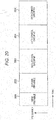
- FIG. 20 is a view illustrating an example of a frame configuration of a modulated signal transmitted by the transmission device in FIG. 17 .
- a vertical axis indicates a frequency
- a horizontal axis indicates time. Then, since a transmission method using a multi-carrier such as an OFDM method is used, there is a plurality of carriers on the vertical axis of frequency.
- FIG. 20 illustrates first preamble 2001, second preamble 2002, data symbol group #1 2003, data symbol group #2 2004, and data symbol group #3 2005.
- a data symbol group may be allocated per video/audio.
- a symbol for transmitting a first video/audio stream is data symbol group #1 (2003).
- a symbol for transmitting a second video/audio stream is data symbol group #2 (2004).
- a symbol for transmitting a third video/audio stream is data symbol group #3 (note that a PLP (Physical Layer Pipe) may be referred to as a data symbol group.
- data symbol group #1 may be referred to as PLP #1
- data symbol group #2 may be referred to as a PLP #2
- data symbol group #3 may be referred to as PLP #3).
- First preamble 2001 and second preamble 2002 include a symbol for performing frequency synchronization and time synchronization (for example, a PSK (Phase Shift Keying) symbol having signal constellation in an in-phase I-quadrature plane known in a transmitter and a receiver), a symbol for transmitting transmission method information of each data symbol group (information for identifying an SISO (Single-Input Single-Output) method, an MISO (Multiple-Input Single-Output) method and an MIMO method)), a symbol for transmitting information related to an error correction code of each data symbol group (for example, a code length (the number of bits of one encoded block) and a coding rate), a symbol for transmitting information related to a modulation method of each data symbol group (in a case of the MISO method or the MIMO method, since there is a plurality of streams, a plurality of modulation methods is specified), a symbol for transmitting transmission method information of the first and second preambles, a symbol for transmitting information related
- information of the number of bits of one encoded block of data symbol group #1 and information of a coding rate used for error correction coding of data symbol group #1, information of the number of bits of one encoded block of data symbol group #2 and information of a coding rate used for error correction coding of data symbol group #2, and information of the number of bits of one encoded block of data symbol group #3 and information of a coding rate used for error correction coding of data symbol group #3 are included in first preamble (2001) and/or second preamble (2002).
- encoder 103 receives an input of information 101 and control information 102.
- Encoder 103 performs error correction coding (including puncturing processing) on information 101 based on the information of number of bits z of one encoded block of the error correction code (LDPC code) included in control information 102, and the information of the coding rate used for the error correction coding included in control information 102.
- Encoder 103 outputs data 104 obtained after the error correction coding.
- encoder 101 performs encoding in "method #A" corresponding to the coding rate 5/15 in order to generate data for forming data symbol group #X (as described above, encoder 101 performs encoding of an LDPC code and performs puncturing (encoder 101 selects bits not to be transmitted, and determines data to be transmitted)).
- encoder 101 performs encoding in "method #A" corresponding to the coding rate 6/15 in order to generate data for forming data symbol group #X (as described above, encoder 101 performs encoding of an LDPC code and performs puncturing (encoder 101 selects bits not to be transmitted, and determines data to be transmitted)).
- encoder 101 performs encoding in "method #A" corresponding to the coding rate 7/15 in order to generate data for forming data symbol group #X (as described above, encoder 101 performs encoding of an LDPC code and performs puncturing (encoder 101 selects bits not to be transmitted, and determines data to be transmitted)).
- encoder 101 performs encoding in "method #A" corresponding to the coding rate 8/15 in order to generate data for forming data symbol group #X (as described above, encoder 101 performs encoding of an LDPC code and performs puncturing (encoder 101 selects bits not to be transmitted, and determines data to be transmitted)).
- encoder 101 performs encoding in "method #B" corresponding to the coding rate 9/15 in order to generate data for forming data symbol group #X (encoder 101 does not perform puncturing as described above).
- encoder 101 performs encoding in "method #B" corresponding to the coding rate 10/15 in order to generate data for forming data symbol group #X (encoder 101 does not perform puncturing as described above).
- encoder 101 performs encoding in "method #B" corresponding to the coding rate 11/15 in order to generate data for forming data symbol group #X (encoder 101 does not perform puncturing as described above).
- encoder 101 performs encoding in "method #B" corresponding to the coding rate 12/15 in order to generate data for forming data symbol group #X (encoder 101 does not perform puncturing as described above).
- encoder 101 performs encoding in "method #B" corresponding to the coding rate 13/15 in order to generate data for forming data symbol group #X (encoder 101 does not perform puncturing as described above).
- encoder 101 performs encoding in "method #B" corresponding to the coding rate 5/15 in order to generate data for forming data symbol group #X (encoder 101 does not perform puncturing as described above).
- encoder 101 performs encoding in "method #B" corresponding to the coding rate 6/15 in order to generate data for forming data symbol group #X (encoder 101 does not perform puncturing as described above).
- encoder 101 performs encoding in "method #B" corresponding to the coding rate 7/15 in order to generate data for forming data symbol group #X (encoder 101 does not perform puncturing as described above).
- encoder 101 performs encoding in "method #B" corresponding to the coding rate 8/15 in order to generate data for forming data symbol group #X (encoder 101 does not perform puncturing as described above).
- encoder 101 performs encoding in "method #B" corresponding to the coding rate 9/15 in order to generate data for forming data symbol group #X (encoder 101 does not perform puncturing as described above).
- encoder 101 performs encoding in "method #B" corresponding to the coding rate 10/15 in order to generate data for forming data symbol group #X (encoder 101 does not perform puncturing as described above).
- encoder 101 performs encoding in "method #B" corresponding to the coding rate 11/15 in order to generate data for forming data symbol group #X (encoder 101 does not perform puncturing as described above).
- encoder 101 performs encoding in "method #B" corresponding to the coding rate 12/15 in order to generate data for forming data symbol group #X (encoder 101 does not perform puncturing as described above).
- encoder 101 performs encoding in "method #B" corresponding to the coding rate 13/15 in order to generate data for forming data symbol group #X (encoder 101 does not perform puncturing as described above).
- encoder 103 receives an input of information 101 and control information 102.
- Encoder 103 performs error correction coding (including puncturing processing) on information 101 based on the information of number of bits z of one encoded block of the error correction code (LDPC code) included in control information 102, and the information of the coding rate used for the error correction coding included in control information 102.
- Encoder 103 outputs data 104 obtained after the error correction coding.
- encoder 101 performs encoding in "method #A" corresponding to the coding rate 5/15 in order to generate data for forming data symbol group #X (as described above, encoder 101 performs encoding of an LDPC code and performs puncturing (encoder 101 selects bits not to be transmitted, and determines data to be transmitted)).
- encoder 101 performs encoding in "method #A" corresponding to the coding rate 6/15 in order to generate data for forming data symbol group #X (as described above, encoder 101 performs encoding of an LDPC code and performs puncturing (encoder 101 selects bits not to be transmitted, and determines data to be transmitted)).
- encoder 101 performs encoding in "method #A" corresponding to the coding rate 7/15 in order to generate data for forming data symbol group #X (as described above, encoder 101 performs encoding of an LDPC code and performs puncturing as described above (encoder 101 selects bits not to be transmitted, and determines data to be transmitted)).
- encoder 101 performs encoding in "method #B" corresponding to the coding rate 8/15 in order to generate data for forming data symbol group #X (encoder 101 does not perform puncturing as described above).
- encoder 101 performs encoding in "method #B" corresponding to the coding rate 9/15 in order to generate data for forming data symbol group #X (encoder 101 does not perform puncturing as described above).
- encoder 101 performs encoding in "method #B" corresponding to the coding rate 10/15 in order to generate data for forming data symbol group #X (encoder 101 does not perform puncturing as described above).
- encoder 101 performs encoding in "method #B" corresponding to the coding rate 11/15 in order to generate data for forming data symbol group #X (encoder 101 does not perform puncturing as described above).
- encoder 101 performs encoding in "method #B" corresponding to the coding rate 12/15 in order to generate data for forming data symbol group #X (encoder 101 does not perform puncturing as described above).
- encoder 101 performs encoding in "method #B" corresponding to the coding rate 13/15 in order to generate data for forming data symbol group #X (encoder 101 does not perform puncturing as described above).
- encoder 101 performs encoding in "method #B" corresponding to the coding rate 5/15 in order to generate data for forming data symbol group #X (encoder 101 does not perform puncturing as described above).
- encoder 101 performs encoding in "method #B" corresponding to the coding rate 6/15 in order to generate data for forming data symbol group #X (encoder 101 does not perform puncturing as described above).
- encoder 101 performs encoding in "method #B" corresponding to the coding rate 7/15 in order to generate data for forming data symbol group #X (encoder 101 does not perform puncturing as described above).
- encoder 101 performs encoding in "method #B" corresponding to the coding rate 8/15 in order to generate data for forming data symbol group #X (encoder 101 does not perform puncturing as described above).
- encoder 101 performs encoding in "method #B" corresponding to the coding rate 9/15 in order to generate data for forming data symbol group #X (encoder 101 does not perform puncturing as described above).
- encoder 101 performs encoding in "method #B" corresponding to the coding rate 10/15 in order to generate data for forming data symbol group #X (encoder 101 does not perform puncturing as described above).
- encoder 101 performs encoding in "method #B" corresponding to the coding rate 11/15 in order to generate data for forming data symbol group #X (encoder 101 does not perform puncturing as described above).
- encoder 101 performs encoding in "method #B" corresponding to the coding rate 12/15 in order to generate data for forming data symbol group #X (encoder 101 does not perform puncturing as described above).
- encoder 101 performs encoding in "method #B" corresponding to the coding rate 13/15 in order to generate data for forming data symbol group #X (encoder 101 does not perform puncturing as described above).
- a configuration of the reception device which receives a modulated signal transmitted by the transmission device in FIG. 17 is as indicated by 150 in FIG. 1 . Operations of control information demodulator 159 and decoder 167 in reception device 150 in FIG. 1 in particular will be described in detail below.
- FIG. 19 is a view illustrating a configuration of a portion related to control information demodulator 159 and decoder 167 in reception device 150 in FIG. 1 .
- Control information demodulator 159 includes one encoded block bit number information/coding rate information estimator 1903.
- One encoded block bit number information/coding rate information estimator 1903 receives an input of baseband signal 1902, and extracts the first preamble and (or) the second preamble illustrated in FIG. 20 . Further, one encoded block bit number information/coding rate information estimator 1903 obtains information of the number of bits of one encoded block and information of a coding rate used for error correction coding from the first preamble and (or) the second preamble.
- One encoded block bit number information/coding rate information estimator 1903 outputs estimation signal 1904 of the information of the number of bits of one encoded block and the information of the coding rate used for error correction coding.
- the transmission device in FIG. 17 transmits a modulated signal of the frame configuration based on FIG. 20 , and reception device 150 in FIG. 1 receives this modulated signal.
- reception device 150 in FIG. 1 performs a demodulating and decoding operation for obtaining data of a necessary data symbol group among a plurality of data symbol groups. Therefore, control information demodulator 159 obtains "information of the number of bits of one encoded block and information of a coding rate used for error correction coding" of the necessary data symbol group.
- Control information demodulator 159 outputs estimation signal 1904 of information of the number of bits of one encoded block and the information of the coding rate used for error correction coding.
- Puncture bit log likelihood ratio generator 1905 receives an input of estimation signal 1904 of the information of the number of bits of one encoded block and the information of the coding rate used for error correction coding. Puncture bit log likelihood ratio generator 1905 determines whether a method used by the transmission device to generate data of a data symbol is "method #A" or "method #B" described with reference to FIGS. 15 and 16 , from the information of the number of bits of one encoded block and the information of the coding rate used for error correction coding based on FIG. 15 or 16 .
- puncture bit log likelihood ratio generator 1905 When it is determined that the method is "method #B,” puncture bit log likelihood ratio generator 1905 generates and outputs log likelihood ratio 106 of bits corresponding to bits (bits which are not transmitted by the transmission device) punctured in the transmission device. Note that that "when it is determined that the method is "method #B,” puncture bit log likelihood ratio generator 1905 generates and outputs log likelihood ratio 106 of bits corresponding to bits (bits which are not transmitted by the transmission device) punctured in the transmission device” as described above, but puncture bit log likelihood ratio generator 1905 generates and outputs log likelihood ratio 106 of bits corresponding to bits (bits which are not transmitted by the transmission device) punctured for a necessary data symbol group.
- puncture bit log likelihood ratio generator 1905 determined as follows for each data symbol group (X is 1, 2 and 3).
- puncture bit log likelihood ratio generator 1905 determines that the method used by the transmission device to generate data of data symbol group #X is "method #B.”
- puncture bit log likelihood ratio generator 1905 determines as follows for each data symbol group (X is 1, 2 and 3).
- estimation signal 1904 of the information of the number of bits of one encoded block and the information of the coding rate used for error correction coding indicates that the information of number of bits z of one encoded block of an error correction code (LDPC code) of data symbol group #X indicates "z being 10000 bits or more and 20000 bits or less," and that the information of the coding rate used for error correction coding of data symbol group #X indicates a coding rate 5/15
- puncture bit log likelihood ratio generator 1905 determines that the method used by the transmission device to generate data of data symbol group #X is "method #A.”
- estimation signal 1904 of the information of the number of bits of one encoded block and the information of the coding rate used for error correction coding indicates that the information of number of bits z of one encoded block of an error correction code (LDPC code) of data symbol group #X indicates "z being 10000 bits or more and 20000 bits or less," and that the information of the coding rate used for error correction coding of data symbol group #X indicates a coding rate 6/15
- puncture bit log likelihood ratio generator 1905 determines that the method used by the transmission device to generate data of data symbol group #X is "method #A.”
- estimation signal 1904 of the information of the number of bits of one encoded block and the information of the coding rate used for error correction coding indicates that the information of number of bits z of one encoded block of an error correction code (LDPC code) of data symbol group #X indicates "z being 10000 bits or more and 20000 bits or less," and that the information of the coding rate used for error correction coding of data symbol group #X indicates a coding rate 7/15
- puncture bit log likelihood ratio generator 1905 determines that the method used by the transmission device to generate data of data symbol group #X is "method #A.”
- estimation signal 1904 of the information of the number of bits of one encoded block and the information of the coding rate used for error correction coding indicates that the information of number of bits z of one encoded block of an error correction code (LDPC code) of data symbol group #X indicates "z being 10000 bits or more and 20000 bits or less," and that the information of the coding rate used for error correction coding of data symbol group #X indicates a coding rate 8/15
- puncture bit log likelihood ratio generator 1905 determines that the method used by the transmission device to generate data of data symbol group #X is "method #B.”
- estimation signal 1904 of the information of the number of bits of one encoded block and the information of the coding rate used for error correction coding indicates that the information of number of bits z of one encoded block of an error correction code (LDPC code) of data symbol group #X indicates "z being 10000 bits or more and 20000 bits or less," and that the information of the coding rate used for error correction coding of data symbol group #X indicates a coding rate 9/15
- puncture bit log likelihood ratio generator 1905 determines that the method used by the transmission device to generate data of data symbol group #X is "method #B.”
- estimation signal 1904 of the information of the number of bits of one encoded block and the information of the coding rate used for error correction coding indicates that the information of number of bits z of one encoded block of an error correction code (LDPC code) of data symbol group #X indicates "z being 10000 bits or more and 20000 bits or less," and that the information of the coding rate used for error correction coding of data symbol group #X indicates a coding rate 10/15
- puncture bit log likelihood ratio generator 1905 determines that the method used by the transmission device to generate data of data symbol group #X is "method #B.”
- estimation signal 1904 of the information of the number of bits of one encoded block and the information of the coding rate used for error correction coding indicates that the information of number of bits z of one encoded block of an error correction code (LDPC code) of data symbol group #X indicates "z being 10000 bits or more and 20000 bits or less," and that the information of the coding rate used for error correction coding of data symbol group #X indicates a coding rate 11/15
- puncture bit log likelihood ratio generator 1905 determines that the method used by the transmission device to generate data of data symbol group #X is "method #B.”
- estimation signal 1904 of the information of the number of bits of one encoded block and the information of the coding rate used for error correction coding indicates that the information of number of bits z of one encoded block of an error correction code (LDPC code) of data symbol group #X indicates "z being 10000 bits or more and 20000 bits or less," and that the information of the coding rate used for error correction coding of data symbol group #X indicates a coding rate 12/15
- puncture bit log likelihood ratio generator 1905 determines that the method used by the transmission device to generate data of data symbol group #X is "method #B.”
- estimation signal 1904 of the information of the number of bits of one encoded block and the information of the coding rate used for error correction coding indicates that the information of number of bits z of one encoded block of an error correction code (LDPC code) of data symbol group #X indicates "z being 10000 bits or more and 20000 bits or less," and that the information of the coding rate used for error correction coding of data symbol group #X indicates a coding rate 13/15
- puncture bit log likelihood ratio generator 1905 determines that the method used by the transmission device to generate data of data symbol group #X is "method #B.”
- estimation signal 1904 of the information of the number of bits of one encoded block and the information of the coding rate used for error correction coding indicates that the information of number of bits z of one encoded block of an error correction code (LDPC code) of data symbol group #X indicates "z being 50000 bits or more and 70000 bits or less," and that the information of the coding rate used for error correction coding of data symbol group #X indicates a coding rate 5/15
- puncture bit log likelihood ratio generator 1905 determines that the method used by the transmission device to generate data of data symbol group #X is "method #B.”
- estimation signal 1904 of the information of the number of bits of one encoded block and the information of the coding rate used for error correction coding indicates that the information of number of bits z of one encoded block of an error correction code (LDPC code) of data symbol group #X indicates "z being 50000 bits or more and 70000 bits or less," and that the information of the coding rate used for error correction coding of data symbol group #X indicates a coding rate 6/15
- puncture bit log likelihood ratio generator 1905 determines that the method used by the transmission device to generate data of data symbol group #X is "method #B.”
- estimation signal 1904 of the information of the number of bits of one encoded block and the information of the coding rate used for error correction coding indicates that the information of number of bits z of one encoded block of an error correction code (LDPC code) of data symbol group #X indicates "z being 50000 bits or more and 70000 bits or less," and that the information of the coding rate used for error correction coding of data symbol group #X indicates a coding rate 7/15
- puncture bit log likelihood ratio generator 1905 determines that the method used by the transmission device to generate data of data symbol group #X is "method #B.”
- estimation signal 1904 of the information of the number of bits of one encoded block and the information of the coding rate used for error correction coding indicates that the information of number of bits z of one encoded block of an error correction code (LDPC code) of data symbol group #X indicates "z being 50000 bits or more and 70000 bits or less," and that the information of the coding rate used for error correction coding of data symbol group #X indicates a coding rate 8/15
- puncture bit log likelihood ratio generator 1905 determines that the method used by the transmission device to generate data of data symbol group #X is "method #B.”
- estimation signal 1904 of the information of the number of bits of one encoded block and the information of the coding rate used for error correction coding indicates that the information of number of bits z of one encoded block of an error correction code (LDPC code) of data symbol group #X indicates "z being 50000 bits or more and 70000 bits or less," and that the information of the coding rate used for error correction coding of data symbol group #X indicates a coding rate 9/15
- puncture bit log likelihood ratio generator 1905 determines that the method used by the transmission device to generate data of data symbol group #X is "method #B.”
- estimation signal 1904 of the information of the number of bits of one encoded block and the information of the coding rate used for error correction coding indicates that the information of number of bits z of one encoded block of an error correction code (LDPC code) of data symbol group #X indicates "z being 50000 bits or more and 70000 bits or less," and that the information of the coding rate used for error correction coding of data symbol group #X indicates a coding rate 10/15
- puncture bit log likelihood ratio generator 1905 determines that the method used by the transmission device to generate data of data symbol group #X is "method #B.”
- estimation signal 1904 of the information of the number of bits of one encoded block and the information of the coding rate used for error correction coding indicates that the information of number of bits z of one encoded block of an error correction code (LDPC code) of data symbol group #X indicates "z being 50000 bits or more and 70000 bits or less," and that the information of the coding rate used for error correction coding of data symbol group #X indicates a coding rate 11/15
- puncture bit log likelihood ratio generator 1905 determines that the method used by the transmission device to generate data of data symbol group #X is "method #B.”
- estimation signal 1904 of the information of the number of bits of one encoded block and the information of the coding rate used for error correction coding indicates that the information of number of bits z of one encoded block of an error correction code (LDPC code) of data symbol group #X indicates "z being 50000 bits or more and 70000 bits or less," and that the information of the coding rate used for error correction coding of data symbol group #X indicates a coding rate 12/15
- puncture bit log likelihood ratio generator 1905 determines that the method used by the transmission device to generate data of data symbol group #X is "method #B.”
- estimation signal 1904 of the information of the number of bits of one encoded block and the information of the coding rate used for error correction coding indicates that the information of number of bits z of one encoded block of an error correction code (LDPC code) of data symbol group #X indicates "z being 50000 bits or more and 70000 bits or less," and that the information of the coding rate used for error correction coding of data symbol group #X indicates a coding rate 13/15
- puncture bit log likelihood ratio generator 1905 determines that the method used by the transmission device to generate data of data symbol group #X is "method #B.”
- the frame configuration of a modulated signal transmitted by the transmission device is described with reference to FIG. 20 .
- the frame configuration is not limited to this, and may be, for example, a frame configuration including one or more data symbol groups or two or more data symbol groups.
- the broadcast (or communication) system according to the present disclosure is described in the above-described exemplary embodiments. However, the present disclosure is not limited to this.
- each exemplary embodiment and the other contents are only examples.
- a “modulation method, an error correction coding method (an error correction code, a code length, a coding rate and the like to be used), control information and the like” are exemplified, each exemplary embodiment and the other contents can be carried out with the same configuration even when other types of a “modulation method, an error correction coding method (an error correction code, a code length, a coding rate and the like to be used), control information and the like" are applied.
- APSK Amplitude Phase Shift Keying
- PAM Pulse Amplitude Modulation
- PSK Phase Shift Keying
- QAM Quadrature Amplitude Modulation
- a method for arranging 16 signal points, 64 signal points or the like in an I-Q plane is not limited to the signal constellation method of the modulation methods described herein. Therefore, a function of outputting an in-phase component and a quadrature component based on a plurality of bits is a function in a mapper.
- the disclosure described herein is applicable to multi-carrier transmission methods such as the OFDM method, and is also applicable to single carrier transmission methods (For example, in a case of a multi-carrier method, symbols are arranged also in a frequency axis, but in a case of a single carrier, symbols are arranged only in a time direction.)
- a spread spectrum communication method is also applicable to baseband signals by using spreading codes.
- a reception device of a terminal and an antenna may be configured separately.
- the reception device includes an interface which receives through a cable an input of a signal received at the antenna or a signal obtained by performing frequency conversion on a signal received at the antenna, and the reception device performs subsequent processing.
- data and information obtained by the reception device are subsequently converted into a video or a sound to be displayed on a display (monitor) or to be output from a speaker.
- the data and the information obtained by the reception device may be subjected to signal processing related to a video or a sound (the signal processing may not be performed), and may be output from an RCA terminal (a video terminal or an audio terminal), a USB (Universal Serial Bus), a USB 2, a USB 3, an HDMI (registered trademark) (High-Definition Multimedia Interface), an HDMI (registered trademark) 2, a digital terminal or the like of the reception device.
- the data and the information obtained by the reception device are modulated by using wireless communication methods (Wi-Fi (registered trademark) (IEEE 802.11a, IEEE 802.11b, IEEE 802.11g, IEEE 802.11n, IEEE802.11ac, IEEE 802.11ad and the like), WiGiG, Bluetooth (registered trademark) and the like) or wired communication methods (optical communication and power line communication), and these pieces of information may be transmitted to other apparatuses.
- a terminal includes a transmission device which transmits information (in this case, the terminal may transmit data including the data and information obtained by the reception device, or may generate modified data from the data and information obtained by the reception device and transmit the modified data).
- a communication and broadcast apparatus such as a broadcast station, a base station, an access point, a terminal and a mobile phone is considered to include the transmission device.
- a communication apparatus such as a television, a radio, a terminal, a personal computer, a mobile phone, an access point and a base station is considered to include the reception device.
- the transmission device and the reception device according to the present disclosure are each also considered to be an apparatus which has a communication function and which can be connected via any interface to a device that executes applications such as a television, a radio, a personal computer and a mobile phone.
- symbols other than a data symbol for example, a pilot symbol (a preamble, a unique word, a postamble, a reference symbol and the like), and a control information symbol may be arranged in frames in any way. Then, these symbols are called a pilot symbol or a control information symbol here, but these symbols may be called in any way and the function itself is important.
- a pilot symbol a preamble, a unique word, a postamble, a reference symbol and the like
- a control information symbol may be arranged in frames in any way. Then, these symbols are called a pilot symbol or a control information symbol here, but these symbols may be called in any way and the function itself is important.
- a symbol is called a control information symbol, but how to call the symbol is not limited to this, and the symbol may be called in another way.
- This symbol is a symbol for transmitting control information such as information of a transmission method (for example, a transmission method, a modulation method, a coding rate of an error correction code, a code length of an error correction code, a method for configuring a frame and a Fourier transform method (size)).
- the pilot symbol only needs to be a symbol modulated by using PSK modulation and known in a transmitter and a receiver (or a receiver may be capable of learning a symbol transmitted by the transmitter by establishing synchronization).
- the receiver performs frequency synchronization, time synchronization, channel estimation (of each modulated signal) (estimation of CSI (Channel State Information), signal detection and like by using this symbol.
- control information symbol is a symbol for transmitting information (for example, a coding rate of a modulation method, an error correction coding method, and the error correction coding method used for communication, and setting information in an upper layer) which needs to be transmitted to a communicating party for realizing communication other than data communication (such as application communication).
- information for example, a coding rate of a modulation method, an error correction coding method, and the error correction coding method used for communication, and setting information in an upper layer
- each exemplary embodiment is carried out as a communication device, but each exemplary embodiment is not limited to this, and can be performed by using this communication method as software.
- the transmission antennas of transmitting stations and base stations, the reception antennas of terminals and the one antenna described in the drawings may include a plurality of antennas.
- a program for executing the above-described communication method may be stored in a ROM (Read Only Memory) in advance, and a CPU (Central Processing Unit) may be caused to operate this program.
- ROM Read Only Memory
- CPU Central Processing Unit
- the program for executing the above-described communication method may be stored in a computer-readable storage medium, and the program stored in the storage medium may be recorded in a RAM (Random Access Memory) of a computer, and the computer may be caused to operate according to this program.
- RAM Random Access Memory
- each configuration of each of the above-described exemplary embodiments and the like may be realized typically as an LSI (Large Scale Integration) which is an integrated circuit.
- LSI Large Scale Integration
- These integrated circuits may be formed separately as one chip, or may be formed as one chip so as to include all or part of the configuration of each exemplary embodiment.
- the integrated circuit is also called an IC (Integrated Circuit), a system LSI, a super LSI and an ultra LSI depending on the degree of integration.
- a technique for circuit integration is not limited to the LSI, and may be realized by a dedicated circuit or a general purpose processor. After manufacturing of the LSI, a programmable FPGA (Field Programmable Gate Array) or a reconfigurable processor which is reconfigurable in connection or settings of circuit cells inside the LSI may be used.
- a programmable FPGA Field Programmable Gate Array
- reconfigurable processor which is reconfigurable in connection or settings of circuit cells inside the LSI may be used.
- the present disclosure is widely applicable to a wireless system which transmits different modulated signals from a plurality of antennas. Moreover, the present disclosure is also applicable in a case where MIMO transmission is performed in a wired communication system having a plurality of transmission locations (for example, a PLC (Power Line Communication) system, an optical communication system, and a DSL (Digital Subscriber Line) system).
- a wired communication system having a plurality of transmission locations (for example, a PLC (Power Line Communication) system, an optical communication system, and a DSL (Digital Subscriber Line) system).
- the transmission method, the reception method, the transmission device and the reception device according to the present disclosure can secure high data reception quality because of high error correction performance.
Landscapes
- Engineering & Computer Science (AREA)
- Physics & Mathematics (AREA)
- Probability & Statistics with Applications (AREA)
- Theoretical Computer Science (AREA)
- Computer Networks & Wireless Communication (AREA)
- Signal Processing (AREA)
- Mathematical Physics (AREA)
- Error Detection And Correction (AREA)
- Detection And Prevention Of Errors In Transmission (AREA)
- Computational Mathematics (AREA)
- General Physics & Mathematics (AREA)
- Mathematical Analysis (AREA)
- Mathematical Optimization (AREA)
- Pure & Applied Mathematics (AREA)
- Algebra (AREA)
- Computing Systems (AREA)
Applications Claiming Priority (3)
| Application Number | Priority Date | Filing Date | Title |
|---|---|---|---|
| US201461994588P | 2014-05-16 | 2014-05-16 | |
| JP2015084884A JP6544620B2 (ja) | 2014-05-16 | 2015-04-17 | 送信装置、受信装置、送信方法および受信方法 |
| PCT/JP2015/002341 WO2015174053A1 (fr) | 2014-05-16 | 2015-05-08 | Procédé d'émission, procédé de réception, dispositif d'émission et dispositif de réception |
Publications (2)
| Publication Number | Publication Date |
|---|---|
| EP3145089A1 true EP3145089A1 (fr) | 2017-03-22 |
| EP3145089A4 EP3145089A4 (fr) | 2017-05-17 |
Family
ID=54779769
Family Applications (1)
| Application Number | Title | Priority Date | Filing Date |
|---|---|---|---|
| EP15792823.5A Withdrawn EP3145089A4 (fr) | 2014-05-16 | 2015-05-08 | Procédé d'émission, procédé de réception, dispositif d'émission et dispositif de réception |
Country Status (4)
| Country | Link |
|---|---|
| US (2) | US10237015B2 (fr) |
| EP (1) | EP3145089A4 (fr) |
| JP (1) | JP6544620B2 (fr) |
| CN (1) | CN106134085B (fr) |
Cited By (1)
| Publication number | Priority date | Publication date | Assignee | Title |
|---|---|---|---|---|
| WO2024245093A1 (fr) * | 2023-05-31 | 2024-12-05 | 深圳市中兴微电子技术有限公司 | Procédé et appareil de décodage, et dispositif électronique et support d'enregistrement |
Families Citing this family (10)
| Publication number | Priority date | Publication date | Assignee | Title |
|---|---|---|---|---|
| JP6544620B2 (ja) * | 2014-05-16 | 2019-07-17 | パナソニックIpマネジメント株式会社 | 送信装置、受信装置、送信方法および受信方法 |
| WO2015182102A1 (fr) | 2014-05-30 | 2015-12-03 | パナソニックIpマネジメント株式会社 | Appareils d'émission et de réception ainsi que procédés d'émission et de réception |
| JP6628124B2 (ja) | 2014-05-30 | 2020-01-08 | パナソニックIpマネジメント株式会社 | 送信装置、受信装置、送信方法および受信方法 |
| CN109314527B (zh) * | 2017-05-05 | 2021-10-26 | 联发科技股份有限公司 | Qc-ldpc编码方法、装置及非暂时性计算机可读介质 |
| CN109586844B (zh) * | 2018-10-30 | 2020-08-04 | 北京航空航天大学 | 一种基于集合的非均等保护译码方法及系统 |
| US11426242B2 (en) | 2019-01-30 | 2022-08-30 | Medtronic Navigation, Inc. | System and method for registration between coordinate systems and navigation of selected members |
| US11911110B2 (en) | 2019-01-30 | 2024-02-27 | Medtronic Navigation, Inc. | System and method for registration between coordinate systems and navigation of selected members |
| CN110995281B (zh) * | 2019-12-21 | 2024-02-27 | 中国电波传播研究所(中国电子科技集团公司第二十二研究所) | 一种适合测井电缆传输的可变码长rs编码方法 |
| CN119254387A (zh) * | 2020-03-31 | 2025-01-03 | 华为技术有限公司 | 用于数据通信的编码方法及装置 |
| CN115441986A (zh) * | 2021-06-04 | 2022-12-06 | 华为技术有限公司 | 一种传输信息的方法及其装置 |
Family Cites Families (23)
| Publication number | Priority date | Publication date | Assignee | Title |
|---|---|---|---|---|
| JP2001144826A (ja) * | 1999-11-11 | 2001-05-25 | Oki Electric Ind Co Ltd | 受信装置及び通信システム |
| US20020157058A1 (en) * | 2001-02-20 | 2002-10-24 | Cute Ltd. | System and method for feedback-based unequal error protection coding |
| MXPA04012517A (es) * | 2002-06-11 | 2005-02-17 | Thomson Licensing Sa | Servidor multimedia con adaptacion simple con condiciones dinamicas de perdida de red. |
| US7702986B2 (en) * | 2002-11-18 | 2010-04-20 | Qualcomm Incorporated | Rate-compatible LDPC codes |
| KR100678182B1 (ko) * | 2003-08-20 | 2007-02-02 | 삼성전자주식회사 | 비동기 광대역 부호분할 다중접속 시스템에서 상향링크 패킷 데이터 서비스 방법 및 장치 |
| US7516391B2 (en) * | 2004-08-16 | 2009-04-07 | Samsung Electronics Co., Ltd | Apparatus and method for coding/decoding block low density parity check code with variable block length |
| US20080028281A1 (en) * | 2005-01-14 | 2008-01-31 | Shunji Miyazaki | Encoding method, decoding method, and devices for same |
| CN101034953B (zh) * | 2006-03-06 | 2010-06-23 | 诺基亚西门子通信系统技术(北京)有限公司 | 应用低密度奇偶校验码进行数据传输的方法 |
| KR100833515B1 (ko) * | 2006-12-05 | 2008-05-29 | 한국전자통신연구원 | 가변 정보 길이 및 가변 부호율을 가진 ldpc 부호의패리티 검사 행렬 생성 방법, 부/복호화 방법 및 이를이용하는 장치 |
| JP2008153760A (ja) * | 2006-12-14 | 2008-07-03 | Samsung Electronics Co Ltd | 情報符号化装置 |
| US7861134B2 (en) * | 2007-02-28 | 2010-12-28 | Cenk Kose | Methods and systems for LDPC coding |
| CN101325474B (zh) * | 2007-06-12 | 2012-05-09 | 中兴通讯股份有限公司 | Ldpc码的混合自动请求重传的信道编码及调制映射方法 |
| JP5354979B2 (ja) * | 2007-07-12 | 2013-11-27 | パナソニック株式会社 | 低密度パリティ検査畳み込み符号(ldpc−cc)符号化器及びldpc−cc復号器 |
| US20100211854A1 (en) * | 2007-08-30 | 2010-08-19 | Zhenyu Wu | Methods and systems for providing different data loss protection |
| KR101502623B1 (ko) * | 2008-02-11 | 2015-03-16 | 삼성전자주식회사 | 저밀도 패리티 검사 부호를 사용하는 통신 시스템에서 채널부호/복호 방법 및 장치 |
| KR101503058B1 (ko) * | 2008-02-26 | 2015-03-18 | 삼성전자주식회사 | 저밀도 패리티 검사 부호를 사용하는 통신 시스템에서의 채널 부호화/복호화 방법 및 장치 |
| CN101630989B (zh) * | 2008-07-14 | 2012-10-03 | 上海华为技术有限公司 | 一种数据发送方法、装置及通信系统 |
| US8495477B2 (en) * | 2010-02-11 | 2013-07-23 | Lg Electronics Inc. | Digital broadcasting system and method for transmitting and receiving digital broadcast signal |
| US8356137B2 (en) * | 2010-02-26 | 2013-01-15 | Apple Inc. | Data storage scheme for non-volatile memories based on data priority |
| US9525516B2 (en) * | 2011-08-30 | 2016-12-20 | Panasonic Corporation | Transmission device and transmission method |
| JP2015128290A (ja) * | 2013-12-27 | 2015-07-09 | パナソニック インテレクチュアル プロパティ コーポレーション オブアメリカPanasonic Intellectual Property Corporation of America | 送信装置、受信装置、送信方法および受信方法 |
| JP6544620B2 (ja) * | 2014-05-16 | 2019-07-17 | パナソニックIpマネジメント株式会社 | 送信装置、受信装置、送信方法および受信方法 |
| JP6628124B2 (ja) * | 2014-05-30 | 2020-01-08 | パナソニックIpマネジメント株式会社 | 送信装置、受信装置、送信方法および受信方法 |
-
2015
- 2015-04-17 JP JP2015084884A patent/JP6544620B2/ja active Active
- 2015-05-08 EP EP15792823.5A patent/EP3145089A4/fr not_active Withdrawn
- 2015-05-08 CN CN201580016216.XA patent/CN106134085B/zh active Active
-
2016
- 2016-10-04 US US15/284,601 patent/US10237015B2/en active Active
-
2019
- 2019-01-30 US US16/261,881 patent/US10666386B2/en active Active
Cited By (1)
| Publication number | Priority date | Publication date | Assignee | Title |
|---|---|---|---|---|
| WO2024245093A1 (fr) * | 2023-05-31 | 2024-12-05 | 深圳市中兴微电子技术有限公司 | Procédé et appareil de décodage, et dispositif électronique et support d'enregistrement |
Also Published As
| Publication number | Publication date |
|---|---|
| CN106134085B (zh) | 2020-10-23 |
| US10666386B2 (en) | 2020-05-26 |
| CN106134085A (zh) | 2016-11-16 |
| JP2015220750A (ja) | 2015-12-07 |
| JP6544620B2 (ja) | 2019-07-17 |
| US20190165885A1 (en) | 2019-05-30 |
| US10237015B2 (en) | 2019-03-19 |
| US20170048020A1 (en) | 2017-02-16 |
| EP3145089A4 (fr) | 2017-05-17 |
Similar Documents
| Publication | Publication Date | Title |
|---|---|---|
| US10666386B2 (en) | Transmission method, reception method, transmission device and reception device | |
| US11923871B2 (en) | Transmitter, receiver, transmission method, and reception method | |
| US12525995B2 (en) | Transmitter, receiver, transmission method, and reception method | |
| US11502782B2 (en) | Transmitting device for performing an encoding process on an information bit sequence using a coding scheme selected from a coding scheme set | |
| US11581995B2 (en) | Transmitting method, receiving method, transmitting apparatus, and receiving apparatus | |
| US12470323B2 (en) | Transmitting device for performing an encoding process on an information bit sequence using a coding scheme selected from a coding scheme set | |
| WO2015174053A1 (fr) | Procédé d'émission, procédé de réception, dispositif d'émission et dispositif de réception | |
| US20250192937A1 (en) | Transmitting method, receiving method, transmitting apparatus, and receiving apparatus | |
| US12261787B2 (en) | Transmitting method, receiving method, transmitting apparatus, and receiving apparatus |
Legal Events
| Date | Code | Title | Description |
|---|---|---|---|
| PUAI | Public reference made under article 153(3) epc to a published international application that has entered the european phase |
Free format text: ORIGINAL CODE: 0009012 |
|
| 17P | Request for examination filed |
Effective date: 20161019 |
|
| AK | Designated contracting states |
Kind code of ref document: A1 Designated state(s): AL AT BE BG CH CY CZ DE DK EE ES FI FR GB GR HR HU IE IS IT LI LT LU LV MC MK MT NL NO PL PT RO RS SE SI SK SM TR |
|
| AX | Request for extension of the european patent |
Extension state: BA ME |
|
| A4 | Supplementary search report drawn up and despatched |
Effective date: 20170419 |
|
| RIC1 | Information provided on ipc code assigned before grant |
Ipc: H03M 13/00 20060101ALI20170411BHEP Ipc: H03M 13/19 20060101AFI20170411BHEP Ipc: H03M 13/11 20060101ALI20170411BHEP |
|
| DAV | Request for validation of the european patent (deleted) | ||
| DAX | Request for extension of the european patent (deleted) | ||
| STAA | Information on the status of an ep patent application or granted ep patent |
Free format text: STATUS: THE APPLICATION HAS BEEN WITHDRAWN |
|
| 18W | Application withdrawn |
Effective date: 20171108 |