EP3145090B1 - Dispositif d'antenne active, système de communication, et procédé d'étalonnage d'émission et de réception - Google Patents
Dispositif d'antenne active, système de communication, et procédé d'étalonnage d'émission et de réception Download PDFInfo
- Publication number
- EP3145090B1 EP3145090B1 EP15792998.5A EP15792998A EP3145090B1 EP 3145090 B1 EP3145090 B1 EP 3145090B1 EP 15792998 A EP15792998 A EP 15792998A EP 3145090 B1 EP3145090 B1 EP 3145090B1
- Authority
- EP
- European Patent Office
- Prior art keywords
- calibration
- radio frequency
- unit
- transmission
- reception
- Prior art date
- Legal status (The legal status is an assumption and is not a legal conclusion. Google has not performed a legal analysis and makes no representation as to the accuracy of the status listed.)
- Active
Links
Images



Classifications
-
- H—ELECTRICITY
- H01—ELECTRIC ELEMENTS
- H01Q—ANTENNAS, i.e. RADIO AERIALS
- H01Q5/00—Arrangements for simultaneous operation of antennas on two or more different wavebands, e.g. dual-band or multi-band arrangements
- H01Q5/20—Arrangements for simultaneous operation of antennas on two or more different wavebands, e.g. dual-band or multi-band arrangements characterised by the operating wavebands
- H01Q5/22—RF wavebands combined with non-RF wavebands, e.g. infrared or optical
-
- H—ELECTRICITY
- H04—ELECTRIC COMMUNICATION TECHNIQUE
- H04B—TRANSMISSION
- H04B17/00—Monitoring; Testing
- H04B17/10—Monitoring; Testing of transmitters
- H04B17/11—Monitoring; Testing of transmitters for calibration
-
- H—ELECTRICITY
- H01—ELECTRIC ELEMENTS
- H01Q—ANTENNAS, i.e. RADIO AERIALS
- H01Q1/00—Details of, or arrangements associated with, antennas
- H01Q1/12—Supports; Mounting means
- H01Q1/22—Supports; Mounting means by structural association with other equipment or articles
- H01Q1/24—Supports; Mounting means by structural association with other equipment or articles with receiving set
-
- H—ELECTRICITY
- H01—ELECTRIC ELEMENTS
- H01Q—ANTENNAS, i.e. RADIO AERIALS
- H01Q9/00—Electrically-short antennas having dimensions not more than twice the operating wavelength and consisting of conductive active radiating elements
- H01Q9/04—Resonant antennas
- H01Q9/06—Details
- H01Q9/065—Microstrip dipole antennas
-
- H—ELECTRICITY
- H03—ELECTRONIC CIRCUITRY
- H03F—AMPLIFIERS
- H03F3/00—Amplifiers with only discharge tubes or only semiconductor devices as amplifying elements
- H03F3/20—Power amplifiers, e.g. Class B amplifiers, Class C amplifiers
- H03F3/24—Power amplifiers, e.g. Class B amplifiers, Class C amplifiers of transmitter output stages
-
- H—ELECTRICITY
- H04—ELECTRIC COMMUNICATION TECHNIQUE
- H04B—TRANSMISSION
- H04B1/00—Details of transmission systems, not covered by a single one of groups H04B3/00 - H04B13/00; Details of transmission systems not characterised by the medium used for transmission
- H04B1/06—Receivers
- H04B1/10—Means associated with receiver for limiting or suppressing noise or interference
-
- H—ELECTRICITY
- H04—ELECTRIC COMMUNICATION TECHNIQUE
- H04B—TRANSMISSION
- H04B1/00—Details of transmission systems, not covered by a single one of groups H04B3/00 - H04B13/00; Details of transmission systems not characterised by the medium used for transmission
- H04B1/02—Transmitters
- H04B1/04—Circuits
- H04B2001/0408—Circuits with power amplifiers
-
- H—ELECTRICITY
- H04—ELECTRIC COMMUNICATION TECHNIQUE
- H04B—TRANSMISSION
- H04B7/00—Radio transmission systems, i.e. using radiation field
- H04B7/02—Diversity systems; Multi-antenna system, i.e. transmission or reception using multiple antennas
- H04B7/04—Diversity systems; Multi-antenna system, i.e. transmission or reception using multiple antennas using two or more spaced independent antennas
- H04B7/06—Diversity systems; Multi-antenna system, i.e. transmission or reception using multiple antennas using two or more spaced independent antennas at the transmitting station
- H04B7/0613—Diversity systems; Multi-antenna system, i.e. transmission or reception using multiple antennas using two or more spaced independent antennas at the transmitting station using simultaneous transmission
- H04B7/0615—Diversity systems; Multi-antenna system, i.e. transmission or reception using multiple antennas using two or more spaced independent antennas at the transmitting station using simultaneous transmission of weighted versions of same signal
- H04B7/0617—Diversity systems; Multi-antenna system, i.e. transmission or reception using multiple antennas using two or more spaced independent antennas at the transmitting station using simultaneous transmission of weighted versions of same signal for beam forming
Definitions
- the present disclosure relates to the field of communications, and particularly to active antenna devices, communication systems, and a transmission and reception calibrating method.
- a communication system architecture including Baseband units (BBUs) and Remote Radio Units (RRUs) is deployed in a Third-Generation (3G) mobile communication network, where the BBUs are connected with the RRUs over optic fibers, and one BBU can support a number of RRUs.
- BBUs Baseband units
- RRUs Remote Radio Units
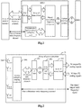
- Fig. 1 illustrates a schematic architectural diagram of a communication system including BBUs and RRUs, where a BBU is connected with an optical interface of an RRU over an optic fiber, the optical interface in the RRU is connected with a digital intermediate-frequency component, and the digital intermediate-frequency component is connected respectively with an array of transceivers, and a transmission and reception calibrating unit.
- the transceivers are connected with an array of Power Amplifiers (PAs) and Low Noise Amplifiers (LNAs)
- the array of PAs and LNAs is connected with an array of passive antenna
- the transmission and reception calibrating unit is connected with the array of passive antennas over a calibration radio frequency channel.
- the RRU is connected with the passive antennas through (N+1) radio frequency jump-up lines, the number of which increases with the increasing number N of antenna radio frequency channels.
- the number N of antenna radio frequency channels is more than or equal to 64, that is, the number of radio frequency jump-up lines is more than 64, and in order to alleviate a transmission loss between the antennas and the RRU, the jump-up lines are typically radio frequency cables with certain diameter, but it is rather difficult to engineer a large number of radio frequency cables, and to guarantee the reliability thereof.
- MIMO Multiple-Input Multiple-Output
- the existing solution to the communication system including the BBUs and the RRUs together with the passive antennas is not feasible in the massive MIMO communication system.
- an antenna system has a plurality of antenna paths and a calibration circuit.
- Each of the antenna paths has a transceiver and an antenna element.
- the calibration circuit has (i) a calibration transceiver and a different coupler coupled to each antenna path.
- the couplers are connected in series with one another and with the calibration transceiver. Connecting the couplers in series, rather than in parallel, reduces the amount of cabling needed and the need for a combiner/splitter or switch matrix between the couplers and the calibration transceiver, thereby reducing the cost, volume, and/or weight associated with the calibration circuit.
- Embodiments of the disclosure provide active antenna devices, communication systems, and a transmission and reception calibrating method so as to carry out an extensible design of an array of antennas to thereby make it less difficult to engineer the array of antennas while guaranteeing the implementation reliability thereof.
- an embodiment of the disclosure provides an active antenna device.
- the active antenna device includes: N arrays of active antennas, a primary calibration coupling circuit unit, a transmission and reception calibrating unit, a calibration parameter storage unit, a Radio Over Fiber (ROF) photoelectric converting unit, where N is more than 1.
- Each of the arrays of active antennas includes at least an antenna calibration coupling circuit unit, and M antenna dipoles connected with the antenna calibration coupling circuit unit, where M is more than 1.
- the antenna calibration coupling circuit units of the arrays of active antennas are connected with the primary calibration coupling circuit unit over a calibration radio frequency channel.
- the primary calibration coupling circuit unit is connected with the transmission and reception calibrating unit.
- the calibration parameter storage unit is configured to store transmission parameters of the calibration radio frequency channels of the N arrays of active antennas and transmit the transmission parameters to the ROF photoelectric converting unit.
- the ROF photoelectric converting unit is configured to convert the transmission parameters into an optical signal and transmit the optical signal over an optic fiber.
- the antenna calibration coupling circuit unit of each array of active arrays is configured to couple received M calibration radio frequency signals into one transmission calibration radio frequency signal and output the one transmission calibration radio frequency signal to the primary calibration coupling circuit unit over the calibration radio frequency channel;
- the primary calibration coupling circuit unit is configured to merge the N transmission calibration radio frequency signals transmitted by the N arrays of active arrays into one transmission calibration radio frequency signal;
- the transmission and reception calibrating unit is configured to amplify the power of the one transmission calibration radio frequency signal transmitted by the primary calibration coupling circuit unit, then demodulate the one transmission calibration radio frequency signal into a transmission calibration In-phase and Quadrature (IQ) analog signal, and output the transmission calibration IQ analog signal to the ROF photoelectric converting unit;
- the ROF photoelectric converting unit is configured to convert the transmission calibration IQ analog signal into an optical signal and transmit the optical signal over the optic fiber.
- the transmission and reception calibrating unit is configured to modulate a reception calibration IQ analog signal transmitted by the ROF photoelectric converting unit into a reception calibration radio frequency signal, amplify the power of the reception calibration radio frequency signal, and then transmit the power-amplified reception calibration radio frequency signal to the primary calibration coupling circuit unit;
- the primary calibration coupling circuit unit is configured to split the power-amplified reception calibration radio frequency signal into N duplicate reception calibration radio frequency signals and transmit the N duplicate reception calibration radio frequency signals to the corresponding antenna calibration coupling circuit units respectively over the calibration radio frequency channel corresponding to the N arrays of active antennas; and each antenna calibration coupling circuit unit is configured to split the received one reception calibration radio frequency signal into M reception calibration radio frequency signals.
- each array of active antennas further includes: an array of filters, an array of Power Amplifiers (PAs) and Low-Noise Amplifiers (LNAs), and an array of transceivers, which are connected sequentially.
- the array of filters is connected with the antenna calibration coupling circuit unit, and the array of transceivers is connected with the ROF photoelectric converting unit.
- the array of filters is configured to filter the M transmission calibration radio frequency signals or the M reception calibration radio frequency signals.
- the array of PAs and LNAs is configured to amplify the power of the M transmission calibration radio frequency signals or the M reception calibration radio frequency signals.
- the array of transceivers is configured to convert the M transmission calibration radio frequency signals or the M reception calibration radio frequency signals into M IQ analog signals, and to transmit the M IQ analog signals; or to convert received M IQ analog signals into the M transmission calibration radio frequency signals or the M reception calibration radio frequency signals.
- the primary calibration coupling circuit unit includes: more than one merger-splitter; or, more than one merger-splitter and more than one coupler; or, more than one switch matrix.
- the transmission and reception calibrating unit includes a radio frequency signal amplifying unit and a transceiver unit, both of which are connected with each other.
- the radio frequency signal amplifying unit is connected with the primary calibration coupling circuit unit, and the transceiver unit is connected with the ROF photoelectric converting unit.
- each array of filters includes M filters independent of each other.
- each array of PAs and LNAs includes M power amplifiers independent of each other and M low-noise amplifiers independent of each other.
- each array of transceivers includes M transceiver units.
- an embodiment of the disclosure provides another active antenna device.
- the active antenna device includes: N arrays of active antennas, a primary calibration coupling circuit unit, a transmission and reception calibrating unit, a calibration parameter storage unit, a digital processing unit, and a digital optic fiber interface unit, where N is more than 1.
- Each of the arrays of active antennas includes at least an antenna calibration coupling circuit unit, and M antenna dipoles connected with the antenna calibration coupling circuit unit, where M is more than 1.
- the antenna calibration coupling circuit units of the arrays of active antennas are connected with the primary calibration coupling circuit unit over a calibration radio frequency channel, the primary calibration coupling circuit unit is connected with the transmission and reception calibrating unit, and the transmission and reception calibrating unit and the calibration parameter storage unit are connected respectively with the digital processing unit.
- the calibration parameter storage unit is configured to store transmission parameters of the calibration radio frequency channel of the N arrays of active antennas and transmit the transmission parameters to the digital processing unit.
- the antenna calibration coupling circuit unit of each array of active arrays is configured to couple received M calibration radio frequency signals into one transmission calibration radio frequency signal, and output the one transmission calibration radio frequency signal to the primary calibration coupling circuit unit over the calibration radio frequency channel;
- the primary calibration coupling circuit unit is configured to merge the N transmission calibration radio frequency signals transmitted by the N arrays of active arrays into one transmission calibration radio frequency signal;
- the transmission and reception calibrating unit is configured to amplify the power of the one transmission calibration radio frequency signal transmitted by the primary calibration coupling circuit unit, then demodulate the one transmission calibration radio frequency signal into a transmission calibration IQ analog signal and output the transmission calibration IQ analog signal to the digital processing unit;
- the digital processing unit is configured to convert the transmission calibration IQ analog signal into a transmission calibration IQ digital signal and transmit the transmission calibration IQ digital signal through the digital optic fiber interface unit.
- the digital processing unit is configured to convert a reception calibration IQ digital signal received by the digital optic fiber interface unit into a reception calibration IQ analog signal;
- the transmission and reception calibrating unit is configured to modulate the reception calibration IQ analog signal transmitted by the digital processing unit into a reception calibration radio frequency signal, amplify the power of the reception calibration radio frequency signal and then transmit the power-amplified reception calibration radio frequency signal to the primary calibration coupling circuit unit;
- the primary calibration coupling circuit unit is configured to split the power-amplified reception calibration radio frequency signal into N duplicate reception calibration radio frequency signals and transmit the N duplicate reception calibration radio frequency signals to the corresponding antenna calibration coupling circuit units respectively over the calibration radio frequency channel corresponding to the N arrays of active antennas; and each antenna calibration coupling circuit unit is configured to split the received one reception calibration radio frequency signal into M reception calibration radio frequency signals.
- each array of active antennas further includes: an array of filters, an array of PAs and LNAs, and an array of transceivers, which are connected sequentially.
- the array of filters is connected with the antenna calibration coupling circuit unit, and the array of transceivers is connected with the digital processing unit.
- the array of filters is configured to filter the M transmission calibration radio frequency signals or the M reception calibration radio frequency signals.
- the array of PAs and LNAs is configured to amplify the power of the M transmission calibration radio frequency signals or the M reception calibration radio frequency signals.
- the array of transceivers is configured to convert the M transmission calibration radio frequency signals or the M reception calibration radio frequency signals into M IQ analog signals, and to transmit the M IQ analog signals; or to convert received M IQ analog signals into the M transmission calibration radio frequency signals or the M reception calibration radio frequency signals.
- the primary calibration coupling circuit unit includes: more than one merger-splitter; or, more than one merger-splitter and more than one coupler; or, more than one switch matrix.
- the transmission and reception calibrating unit includes a radio frequency signal amplifying unit and a transceiver unit, both of which are connected with each other.
- the radio frequency signal amplifying unit is connected with the primary calibration coupling circuit unit, and the transceiver unit is connected with the digital processing unit.
- an embodiment of the disclosure provides another communication system.
- the communication system includes the active antenna device according to any of the implementations of the second aspect and a baseband building device.
- the active antenna device and the baseband building device are connected over an optic fiber
- the baseband building device includes a digital optic fiber interface unit and a baseband unit.
- the digital optic fiber interface unit and the baseband unit are connected with each other.
- the baseband unit is configured to convert one preset reception calibration sequence into one reception calibration IQ digital signal and transmit the one reception calibration IQ digital signal to the digital optic fiber interface unit, and the digital optic fiber interface unit is configured to transmit the one reception calibration IQ digital signal over the optic fiber; and the baseband unit is configured to receive N*M reception calibration IQ digital signals transmitted by the digital optic fiber interface unit, revise the N*M reception calibration IQ digital signals using preset transmission parameters of N*M calibration radio frequency channels, and calculate reception calibration amplitude revision parameters and reception calibration phase revision parameters corresponding to respective radio frequency channels corresponding to the N*M calibration radio frequency channels according to the revised N*M reception calibration IQ digital signals, and the one preset reception calibration sequence.
- the baseband unit is configured to convert N*M preset transmission calibration sequences into N*M transmission calibration IQ digital signals, revise the N*M transmission calibration IQ digital signals using the preset transmission parameters of the N*M calibration radio frequency channels, and transmit the revised N*M transmission calibration IQ digital signals to the digital optic fiber interface unit, and the digital optic fiber interface unit is configured to convert the revised N*M transmission calibration IQ digital signals into an optical signal and transmit the optical signal over the optic fiber; and the baseband unit is configured to receive one transmission calibration IQ digital signal transmitted by the digital optic fiber interface unit and calculate transmission calibration amplitude revision parameters and transmission calibration phase revision parameters of the respective radio frequency channels corresponding to the N*M calibration radio frequency channels according to the received one transmission calibration IQ digital signal, and the N*M preset transmission calibration sequences.
- the received N*M reception calibration IQ digital signals are signals obtained after the one reception calibration IQ digital signal has been transmitted firstly over one calibration radio frequency channel of the active antenna device and then over N*M radio frequency channels of the active antenna device, and then received over the optic fiber and processed by the digital optic fiber interface unit.
- the received one transmission calibration IQ digital signal is a signal obtained after the revised N*M transmission calibration IQ digital signals have been transmitted firstly over the N*M radio frequency channels of the active antenna device and then over the calibration radio frequency channel of the active antenna device, and then received over the optic fiber and processed by the digital optic fiber interface unit.
- the preset transmission parameters of the N*M calibration radio frequency channels are received over the optic fiber, and then transmitted by the digital optic fiber interface unit to the baseband unit.
- the baseband unit is further configured to: obtain uplink data, revise the amplitude of the uplink data using the reception calibration amplitude revision parameters, and revise the phase of the uplink data using the reception calibration phase revision parameters.
- the uplink data is obtained as a result of an uplink signal being received over the optic fiber, and transmitted by the digital optic fiber interface unit to the baseband unit.
- the baseband unit is further configured to: perform beam-forming on data to be transmitted, revise the amplitude of the beam-formed data using the transmission calibration amplitude revision parameters, revise the phase of the beam-formed data using the transmission calibration phase revision parameters, and then transmit the data to the digital optic fiber interface unit, so that the digital optic fiber interface unit converts the data into an optical signal, and then transmits the optical signal over the optic fiber.
- the antenna calibration coupling circuit unit, the calibration radio frequency channel, the primary calibration coupling circuit unit, the transmission and reception calibrating unit, and the calibration parameter storage unit are additionally arranged in the active antenna unit to thereby provide a hardware support for transmission and reception calibration, so that transmission and reception calibration on the respective radio frequency channels can be performed using the active antenna device including the calibration radio frequency channel and the calibration circuit, and the extensible design of the antenna radio frequency channels can be carried out using the active antenna unit while guaranteeing uniform performance of the respective antenna radio frequency channels to thereby make it less difficult to engineer the array of antennas while guaranteeing the implementation reliability thereof.
- N radio frequency channels are not uniform, then N uplink signals or downlink signals may not be merged for optimum performance, so it will be crucial to calibrate the N radio frequency channels.
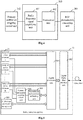
- an array of active antennas 21 as illustrated in Fig. 2 including an array of filters 201, an array of PAs and LNAs 202, and an array of transceivers 203, which are connected sequentially, and M antenna dipoles 204, where M is more than 1, the M antenna dipoles 204 are connected with an antenna calibration coupling circuit unit 205, and the antenna calibration coupling circuit unit 205 is connected with the array of filters 201, and further with one calibration radio frequency channel.
- the M antenna dipoles 204 are configured to receive and convert an electromagnetic wave into M radio frequency signals, or to receive and convert M radio frequency signals into an electromagnetic wave, and then transmit the electromagnetic wave.
- the antenna calibration coupling circuit unit 205 is configured to transmit the radio frequency signals between the array of filters 201 and the M antenna dipoles 204 while the radio frequency signals are being transmitted; and to couple M calibration radio frequency signals transmitted by the array of filters 201 into one calibration radio frequency signal, and to output the calibration radio frequency signal over the calibration radio frequency channel; or to receive one calibration radio frequency signal over the calibration radio frequency channel, to split the received calibration radio frequency signal into M calibration radio frequency signals, and to transmit the M calibration radio frequency signals to the array of filters 201, while the received or transmitted signals are being calibrated.
- the array of filters 201 is configured to filter the M radio frequency signals.
- the array of PAs and LNAs 202 is configured to amplify power of the M radio frequency signals.
- the array of transceivers 203 is configured to convert the M radio frequency signals into M IQ analog signals, and to transmit the M IQ analog signals; or to convert received M IQ analog signals into the radio frequency signals.
- the array of filters 201 includes M filters independent of each other.
- the array of PAs and LNAs 202 includes M power amplifier independent of each other, and M low-noise amplifiers independent of each other.
- the array of transceivers 203 includes M transceiver units.
- the antenna dipoles 204 can be uni-polarized antenna dipoles, or can be duly- polarized antenna dipoles or multi-polarized antenna dipoles.
- the array of transceivers modulates and up-converts input M IQ analog signals into M radio frequency signals; the power of the M radio frequency signals is amplified by the array of PAs and LNAs, and the M radio frequency signals are filtered by the array of filters into M radio frequency signals with a corresponding spectrum; and the M radio frequency signals with the corresponding spectrum are transmitted by the antenna calibration coupling circuit unit to the M antenna dipoles, and converted by the M antenna dipoles into the electromagnetic wave, and the electromagnetic wave is transmitted to the space.
- the M antenna dipoles convert the received electromagnetic wave from the space into M radio frequency signals, and the M radio frequency signals are transmitted by the antenna calibration coupling circuit unit to the array of filters for radio frequency filtering into M radio frequency signals with a corresponding spectrum; the power of the M radio frequency signals with the corresponding spectrum is amplified by the array of PAs and LNAs, and then the M radio frequency signals with the corresponding spectrum are output to the array of transceivers; and the array of transceivers down-converts and demodulates the M radio frequency signals from the array of PAs and LNAs into M IQ analog signals, and outputs the M IQ analog signals.
- M transmission calibration IQ analog signals are input to the array of transceivers, and modulated and up-converted by the array of transceivers into M transmission calibration radio frequency signals; the power of the M transmission calibration radio frequency signals is amplified by the array of PAs and LNAs, and the M transmission calibration radio frequency signals are filtered by the array of filters into M transmission calibration radio frequency signals with a corresponding spectrum; and the M transmission calibration radio frequency signals with the corresponding spectrum are input to the antenna calibration coupling circuit unit, and coupled by the antenna calibration coupling circuit unit into one transmission calibration radio frequency signal, and the one transmission calibration radio frequency signal is output over the one calibration radio frequency channel.
- one reception calibration radio frequency signal is input to the antenna calibration coupling circuit unit, over the one calibration radio frequency channel, and split by the antenna calibration coupling circuit unit into M reception calibration radio frequency signals, and the M reception calibration radio frequency signals are output to the array of filters for radio frequency filtering into M reception calibration radio frequency signals with a corresponding spectrum;
- the power of the M reception calibration radio frequency signals with the corresponding spectrum is power-amplified by the array of PAs and LNAs, and then the power-amplified M reception calibration radio frequency signals with the corresponding spectrum are output to the array of transceivers; and the array of transceivers down-converts and demodulates the M reception calibration radio frequency signals with the corresponding spectrum from the array of PAs and LNA into M reception calibration IQ analog signals, and outputs the M reception calibration IQ analog signals.
- the antenna calibration coupling circuit unit will receive M radio frequency signals from the array of filters, and transmit the M radio frequency signals to the M antenna dipoles, while the signals are being transmitted; and the antenna calibration coupling circuit unit will receive radio frequency signals from the M antenna dipoles, and transmit the M radio frequency signals to the array of filters, while the signals are being received.
- the antenna calibration coupling circuit unit While the system operates in antenna radio frequency channel calibration, then the antenna calibration coupling circuit unit will receive M calibration radio frequency signals from the array of filters and couple the M calibration radio frequency signals to the one calibration radio frequency channel and output as one calibration radio frequency signal, during transmission calibration; and the antenna calibration coupling circuit unit will receive an input of a calibration radio frequency signal from the one calibration radio frequency channel, couple the input calibration radio frequency signal into M calibration radio frequency signals, and transmit the M calibration radio frequency signals to the array of filters, during reception calibration.
- the array of filters performs radio frequency filtering on radio frequency signals, and controls the transmitted and received radio frequency signals to lie within certain range of frequencies to thereby alleviate inter-system interference.
- the array of filters perform radio filtering on the radio frequency signals from the array of PAs and LNAs, and transmit the filtered radio frequency signals to the antennal calibration coupling circuit unit, while the signals are being transmitted.
- the array of filters performs radio filtering on the radio frequency signals from the antennal calibration coupling circuit unit, and transmit the filtered radio frequency signals to the array of PAs and LNAs, while the signals are being received.
- the array of PAs and LNAs amplifies the power of transmission (or reception) signals by amplifying the power of the M radio frequency signals from the array of transceivers, and inputting the power-amplified M radio frequency signals to the array of filters, while the signals are being transmitted; and amplifying the power of the M radio frequency signals from the array of filters, and inputting the power-amplified M radio frequency signals to the array of transceivers, while the signals are being received.
- the array of transceivers modules and up-converts input M IQ analog signals into radio frequency signals, and outputs the radio frequency signals to the array of PAs and LNAs, while the signals are being transmitted; and down-converts and demodulates M radio frequency signals from the array of PAs and LNAs into M IQ analog signals while the signals are being received.
- an active antenna device 31 as illustrated in Fig. 3 , where the massive active antenna unit includes an ROF photoelectric converting unit 301 and N arrays of active antennas 21, where N is more than 1, and the massive active antenna unit further includes a primary calibration coupling circuit unit 302 and a transmission and reception calibrating unit 303; and further includes a calibration parameter storage unit 304 connected with the ROF photoelectric converting unit 301.
- each array of active antennas 21 includes an array of filters 201, an array of PAs and LNAs 202, and an array of transceivers 203, which are connected sequentially, and M antenna dipoles 204, where M is more than 1, the M antenna dipoles 204 are connected with an antenna calibration coupling circuit unit 205, and the antenna calibration coupling circuit unit 205 is connected with the array of filters 201, and further with one calibration radio frequency channel.
- the antenna calibration coupling circuit unit 205 of each array of active antennas 21 is connected with the primary calibration coupling circuit unit 302 over the calibration radio frequency channel, the primary calibration coupling circuit unit 302 is connected with the transmission and reception calibrating unit 303, and the transmission and reception calibrating unit 303 and the calibration parameter storage unit 304 are connected respectively with the ROF photoelectric converting unit 301.
- the calibration parameter storage unit 304 is configured to store transmission parameters of the calibration radio frequency channels of the N arrays of active antennas 21, and to transmit the stored transmission parameters to the ROF photoelectric converting unit 301, so that the ROF photoelectric converting unit 301 converts the transmission parameters into an optical signal, and transmits the optical signal over an optic fiber.
- the N arrays of active antennas can be configured in a planar array structure, a cylindrical structure, or any other possible structure.
- ROF photoelectric converting unit 301 and the arrays of active antennas 21 process signals being received, and signals being transmitted in different processes particularly as follows.
- each array of active antennas 21 converts a received electromagnetic wave into M radio frequency signals through the M antenna dipoles 204, and the antenna calibration coupling circuit unit 205 receives and transmits the M radio frequency signals to the array of filters 201, so that the M radio frequency signals are filtered by the array of filters 201, and then transmitted to the array of PAs and LNAs 202 for power amplification, and the power-amplified M radio frequency signals are converted by the array of transceivers 203 into M IQ analog signals , and the M IQ analog signals are transmitted to the ROF photoelectric converting unit 301; and, the ROF photoelectric converting unit 301 converts the N*M IQ analog signals transmitted by the N arrays of active antennas 21 into an optical signal, and transmits the optical signal over the optic fiber.
- the ROF photoelectric converting unit 301 converts an optical signal received over the optic fiber into N*M IQ analog signals, splits the N*M IQ analog signals into N groups, and transmits the N groups of IQ analog signals respectively to the N arrays of active antennas 21; and, each array of active antennas 21 converts the M IQ analog signals received through the array of transceivers 203 into M radio frequency signals; and then the power of the M radio frequency signals is amplified by the array of PAs and LNAs 202, and the power-amplified M radio frequency signals are filtered by the array of filters 201, and then the filtered M radio frequency signals are transmitted by the antenna calibration coupling circuit unit 205 respectively to the M antenna dipoles 204, and converted by the M antenna dipoles 204 into an electromagnetic wave which is further transmitted.
- the antenna calibration coupling circuit unit 205 of each array of active arrays 21 couples received M calibration radio frequency signals into one transmission calibration radio frequency signal, and outputs the one transmission calibration radio frequency signal to the primary calibration coupling circuit unit 302 over the calibration radio frequency channel;
- the primary calibration coupling circuit unit 302 merges the N transmission calibration radio frequency signals transmitted by the N arrays of active arrays 21 into one transmission calibration radio frequency signal;
- the transmission and reception calibrating unit 303 amplifies the power of the one transmission calibration radio frequency signal transmitted by the primary calibration coupling circuit unit 302, and then demodulates the one transmission calibration radio frequency signal into a transmission calibration IQ analog signal, and outputs the transmission calibration IQ analog signal to the ROF photoelectric converting unit 301;
- the ROF photoelectric converting unit 301 converts the transmission calibration IQ analog signal into an optical signal, and transmits the optical signal over the optic fiber.
- the transmission and reception calibrating unit 303 modulates a reception calibration IQ analog signal transmitted by the ROF photoelectric converting unit 301 into a reception calibration radio frequency signal, amplifies the power of the reception calibration radio frequency signal, and then transmits the power-amplified reception calibration radio frequency signal to the primary calibration coupling circuit unit 302; the primary calibration coupling circuit unit 302 splits the power-amplified reception calibration radio frequency signal into N duplicate reception calibration radio frequency signals, and transmits the N duplicate reception calibration radio frequency signals to the corresponding antenna calibration coupling circuit units 205 respectively over the calibration radio frequency channel corresponding to the N arrays of active antennas 21; and each antenna calibration coupling circuit unit 205 splits the received one reception calibration radio frequency signal into M reception calibration radio frequency signals.
- the primary calibration coupling circuit unit 302 includes more than one merger-splitter, or more than one merger-splitter and coupler, or more than one switch matrix.
- the transmission and reception calibrating unit 303 includes a radio frequency signal amplifying unit 401 and a transceiver unit 402, both of which are connected with each other, and particularly the radio frequency signal amplifying unit 401 is connected with the primary calibration coupling circuit unit 302, and the transceiver unit 402 is connected with the ROF photoelectric converting unit 301.
- the transmission and reception calibrating unit amplifies the power of the one transmission calibration radio frequency signal from the primary calibration coupling circuit unit, down-converts and demodulates the one transmission calibration radio frequency signal into the transmission calibration IQ analog signal, and outputs the transmission calibration IQ analog signal to the ROF photoelectric converting unit.
- the transmission and reception calibrating unit modulates and up-converts the reception calibration IQ analog signal from the ROF photoelectric converting unit into the reception calibrated radio frequency signal, amplifies the radio frequency power of the reception calibrated radio frequency signal, and outputs the power-amplified reception calibrated radio frequency signal to the primary calibration coupling circuit unit.
- each array of filters 201 includes M filters independent of each other.
- each array of PAs and LNAs 202 includes M power amplifiers independent of each other, and M low-noise amplifiers independent of each other.
- each array of transceivers 203 includes M transceiver units.
- an active antenna device 51 as illustrated in Fig. 5 , where the massive active antenna device includes a digital processing unit 501, an optic fiber interface unit 502, a primary calibration coupling circuit unit 503, a transmission and reception calibrating unit 504, and N arrays of active antennas 21, where N is more than 1.
- the N arrays of active antennas 21 are connected respectively with the digital processing unit 501, and the digital processing unit 501 is connected with the optic fiber interface unit 502.
- the active antenna unit 51 further includes a calibration parameter storage unit 505 connected with the digital processing unit 501.
- each array of active antennas 21 includes an array of filters 201, an array of PAs and LNAs 202, and an array of transceivers 203, which are connected sequentially, and M antenna dipoles 204, where M is more than 1, the M antenna dipoles 204 are connected with an antenna calibration coupling circuit unit 205, and the antenna calibration coupling circuit unit 205 is connected with the array of filters 201, and further with one calibration radio frequency channel.
- the antenna calibration coupling circuit unit 205 of each array of active antennas 21 is connected with the primary calibration coupling circuit unit 503 over the calibration radio frequency channel, the primary calibration coupling circuit unit 503 is connected with the transmission and reception calibrating unit 504, and the transmission and reception calibrating unit 504, and the calibration parameter storage unit 505 are connected respectively with the digital processing unit 501.
- the calibration parameter storage unit 505 is configured to store transmission parameters of the calibration radio frequency channels of the N arrays of active antennas 21, and to transmit the transmission parameters to the digital processing unit 501.
- the N arrays of active antennas can be configured in a planar array structure, a cylindrical structure, or any other possible structure.
- signals being received, and signals being transmitted are processed in different processes particularly as follows.
- each array of active antennas 21 converts a received electromagnetic wave into M radio frequency signals through the M antenna dipoles 204, and transmits the M radio frequency signals to the array of filters 201 through the antenna calibration coupling circuit unit 205; the M radio frequency signals are filtered by the array of filters 201, and then transmitted to the array of PAs and LNAs 202 for power amplification; and the power-amplified M radio frequency signals are converted by the array of transceivers 203 into M IQ analog signals and then the M IQ analog signals are transmitted to the digital processing unit 501; the digital processing unit 501 converts the N*M IQ analog signals transmitted by the N arrays of active antennas 21 into N*M IQ digital signals; and, the optic fiber interface unit 502 converts the N*M IQ digital signals transmitted by the digital processing unit 501 into an optical signal, and transmits the optical signal over the optic fiber.
- the optic fiber interface unit 502 converts an optical signal received over the optic fiber into N*M IQ digital signals
- the digital processing unit 501 converts the N*M IQ digital signals transmitted by the optic fiber interface unit 502 into N*M IQ analog signals, divides the N*M IQ analog signals into N groups, and transmits the N groups of IQ analog signals respectively to the N arrays of active antennas 21
- each array of active antennas 21 converts the M IQ analog signals received through the array of transceivers 203 into M radio frequency signals
- the power of the M radio frequency signals is amplified by the array of PAs and LNAs 202, and the power-amplified M radio frequency signals are filtered by the array of filters 201, and then the filtered M radio frequency signals are transmitted by the antenna calibration coupling circuit unit 205 respectively to the M antenna dipoles 204, and converted by the M antenna dipoles 204 into an electromagnetic wave which is further transmitted.
- the antenna calibration coupling circuit unit of each array of active antennas couples received M calibration radio frequency signals into one transmission calibration radio frequency signal, and outputs the one transmission calibration radio frequency signal to the primary calibration coupling circuit unit over the calibration radio frequency channel;
- the primary calibration coupling circuit unit merges the N transmission calibration radio frequency signals transmitted by the N arrays of active antennas into one transmission calibration radio frequency signal;
- the transmission and reception calibrating unit amplifies the power of the one transmission calibration radio frequency signal transmitted by the primary calibration coupling circuit unit, and then demodulates the one transmission calibration radio frequency signal into a transmission calibration IQ analog signal, and outputs the transmission calibration IQ analog signal to the digital processing unit;
- the digital processing unit converts the transmission calibration IQ analog signal into a transmission calibration IQ digital signal, and transmits the transmission calibration IQ digital signal through the optic fiber interface unit.
- the N arrays of active antennas receive N*M transmission calibration IQ analog signals from the digital processing unit, converts the N*M transmission calibration IQ analog signals into N*M transmission calibration radio frequency signals, couples the N*M transmission calibration radio frequency signals into N transmission calibration radio frequency signals, and outputs the N transmission calibration radio frequency signals to the primary calibration coupling circuit unit.
- the digital processing unit converts a reception calibration IQ digital signal received through the optic fiber interface unit into a reception calibration IQ analog signal
- the transmission and reception calibrating unit modulates the reception calibration IQ analog signal transmitted by the digital processing unit into a reception calibration radio frequency signal, amplifies the power of the reception calibration radio frequency signal, and then transmits the reception calibration radio frequency signal to the primary calibration coupling circuit unit
- the primary calibration coupling circuit unit splits the power-amplified reception calibration radio frequency signal into N duplicate reception calibration radio frequency signals, and transmits the N duplicate reception calibration radio frequency signals to the corresponding antenna calibration coupling circuit units respectively over the calibration radio frequency channel corresponding to the N arrays of active antennas
- each antenna calibration coupling circuit unit splits the received one reception calibration radio frequency signal into M reception calibration radio frequency signals.
- the N arrays of active antennas receive N reception calibration radio frequency signals from the primary calibration coupling circuit unit, split the received N reception calibration radio frequency signals into N*M reception calibration radio frequency signals, convert the N*M reception calibration radio frequency signals into N*M reception calibration IQ analog signals, and output the N*M reception calibration IQ analog signals to the digital processing unit.
- the primary calibration coupling circuit unit 503 includes more than one merger-splitter, or more than one merger-splitter and coupler, or more than one switch matrix.
- the transmission and reception calibrating unit 504 includes a radio frequency signal amplifying unit and a transceiver unit, both of which are connected with each other, and particularly the radio frequency signal amplifying unit is connected with the primary calibration coupling circuit unit 503, and the transceiver unit is connected with the digital processing unit 501.
- the transmission and reception calibrating unit amplifies the power of the one transmission calibration radio frequency signal from the primary calibration coupling circuit unit, down-converts and demodulates the one power-amplified transmission calibration radio frequency signal into the transmission calibration IQ analog signal, and outputs the transmission calibration IQ analog signal to the digital processing unit.
- the transmission and reception calibrating unit modulates and up-converts the reception calibration IQ analog signal received from the digital processing unit into the reception calibrated radio frequency signal, amplifies the radio frequency power of the reception calibrated radio frequency signal, and outputs the power-amplified reception calibrated radio frequency signal to the primary calibration coupling circuit unit.
- each array of filters 201 includes M filters independent of each other.
- each array of PAs and LNAs 202 includes M power amplifier independent of each other, and M low-noise amplifiers independent of each other.
- each array of transceivers 203 includes M transceiver units.
- a baseband building device 61 as illustrated in Fig. 6 including an ROF photoelectric converting unit 601, a digital processing unit 602, and a baseband unit 603, which are connected sequentially.
- signals being received, and signals being transmitted are processed in different processes particularly as follows.
- the ROF photoelectric converting unit 601 converts a received optical signal into N*M IQ analog signals, where N is more than 1, and M is more than 1;
- the digital processing unit 602 converts the N*M IQ analog signals received from the ROF photoelectric converting unit 601 into N*M IQ digital signals;
- the baseband unit 603 performs data processing in the N*M IQ digital signals received from the digital processing unit 602 to obtain received data.
- signals are transmitted particularly as follows: the baseband unit 603 performs data process in the data to be transmitted and obtains N*M IQ digital signals; the digital processing unit 602 converts the N*M IQ digital signals received from the baseband unit 603 into N*M IQ analog signals; and, the ROF photoelectric converting unit 601 converts the N*M IQ analog signals received from the digital processing unit 602 into an optical signal, and transmits the optical signal over the optic fiber.
- the baseband unit converts one preset reception calibration sequence into one reception calibration IQ digital signal, and transmits the one reception calibration IQ digital signal to the digital processing unit; and receives N*M reception calibration IQ digital signals, revises the N*M reception calibration IQ digital signals using N*M preset transmission parameters of calibration radio frequency channels, and calculates reception calibration amplitude revision parameters and reception calibration phase revision parameters corresponding to respective radio frequency channels corresponding to the calibration radio frequency channels according to the revised N*M reception calibration IQ digital signals, and the reception calibration sequence.
- the received N*M reception calibration IQ digital signals are obtained as a result of the one reception calibration IQ digital signal being transmitted over the one calibration radio frequency channel and the N*M radio frequency channels of the active antenna device in that order, and then received over the optic fiber, and processed by the ROF photoelectric converting unit and the digital processing unit.
- N*M preset transmission parameters of the calibration radio frequency channel are received over the optic fiber, and then transmitted by the ROF photoelectric converting unit and the digital processing unit to the baseband unit.
- the baseband unit 603 obtains uplink data, revises the amplitude of the uplink data using the reception calibration amplitude revision parameters, and revises the phase of the uplink data using the reception calibration phase revision parameters.
- the uplink data is obtained as a result of an uplink signal being received over the optic fiber, and then transmitted by the ROF photoelectric converting unit 601 and the digital processing unit 602 to the baseband unit 603.
- the baseband unit converts N*M preset transmission calibration sequences into N*M transmission calibration IQ digital signals, revises the N*M transmission calibration IQ digital signals of the corresponding calibration radio frequency channels using the N*M preset transmission parameters of the calibration radio frequency channels, and transmits the revised N*M transmission calibration IQ digital signals to the digital processing unit, and the digital processing unit converts the revised N*M transmission calibration IQ digital signals into N*M transmission calibration IQ analog signals, and then the ROF photoelectric converting unit converts the N*M transmission calibration IQ analog signals into an optical signal, and transmits the optical signal over the optic fiber; and the baseband unit receives one transmission calibration IQ digital signal, and calculates transmission calibration amplitude revision parameters and transmission calibration phase revision parameters of the respective radio channels corresponding to the calibration radio frequency channel according to the received one transmission calibration IQ digital signal, and the N*M preset transmission calibration sequences.
- the received one transmission calibration IQ digital signal is obtained as a result of the revised N*M transmission calibration IQ digital signals being transmitted over the N*M radio frequency channels and the one calibration radio frequency channel of the active antenna device in that order, and then received over the optic fiber, and processed by the ROF photoelectric converting unit and the digital processing unit.
- N*M preset transmission parameters of the calibration radio frequency channels are received over the optic fiber, and then transmitted by the ROF photoelectric converting unit and the digital processing unit to the baseband unit.
- the baseband unit 603 performs beam-forming on data to be transmitted, revises the amplitude of the beam-formed data using the transmission calibration amplitude revision parameters, revises the phase of the beam-formed data using the transmission calibration phase revision parameters, and then transmits the data to the digital processing unit 602, and the data is processed by the digital processing unit 602 and the ROF photoelectric converting unit 601, and then transmitted over the optic fiber.
- the baseband unit performs beam-forming, signal detection, calibration detection, calibration compensation, and other functions.
- the calibration detection function includes transmission calibration, reception calibration, etc.
- the calibration compensation function includes transmission calibration compensation and reception calibration compensation.
- the baseband unit performs beam-forming and transmission calibration compensation on the data to be transmitted, and then generates and outputs N*M IQ digital signals to the digital processing unit.
- the baseband unit performs reception calibration compensation on N*M IQ digital signals from the digital processing unit, and then performs signal detection thereon to obtain received data.
- a baseband building device 71 as illustrated in Fig. 7 , where the massive baseband building device 71 includes an optic fiber interface unit 701 and a baseband unit 702, both of which are connected with each other.
- signals being received, and signals being transmitted are processed in different processes particularly as follows.
- the optic fiber interface unit 701 converts a received optical signal into N*M IQ digital signals, where N is more than 1, and M is more than 1; and, the baseband unit 702 performs data processing on the N*M IQ digital signals received from the optic fiber interface unit 701 to obtain receive data.
- the baseband unit 702 processes data to be transmitted into N*M IQ digital signals; and, the optic fiber interface unit 701 converts the N*M IQ digital signals received from the baseband unit 702 into an optical signal, and transmits the optical signal over the optic fiber.
- the baseband unit converts one preset reception calibration sequence into one reception calibration IQ digital signal, and transmits the one reception calibration IQ digital signal to the optic fiber interface unit, and the optic fiber interface unit transmits the one reception calibration IQ digital signal over the optic fiber; and the baseband unit receives N*M reception calibration IQ digital signals transmitted by the optic fiber interface unit, revises the N*M reception calibration IQ digital signals using N*M preset transmission parameters of calibration radio frequency channels, and calculates reception calibration amplitude revision parameters and reception calibration phase revision parameters corresponding to respective radio frequency channels corresponding to the calibration radio frequency channels according to the revised N*M reception calibration IQ digital signals, and the reception calibration sequence.
- the received N*M reception calibration IQ digital signals are obtained as a result of the one reception calibration IQ digital signal being transmitted over the one calibration radio frequency channel and the N*M radio frequency channels of the active antenna device in that order, and then received over the optic fiber, and processed by the optic fiber interface unit.
- N*M preset transmission parameters of the calibration radio frequency channels are received over the optic fiber, and then transmitted by the optic fiber interface unit to the baseband unit.
- the baseband unit 702 obtains uplink data, revises the amplitude of the uplink data using the reception calibration amplitude revision parameters, and revises the phase of the uplink data using the reception calibration phase revision parameters.
- the uplink data is obtained as a result of an uplink signal being received over the optic fiber, and then transmitted by the optic fiber interface unit 701 to the baseband unit 702.
- the baseband unit converts N*M preset transmission calibration sequences into N*M transmission calibration IQ digital signals, revises the N*M transmission calibration IQ digital signals of the corresponding calibration radio frequency channels using the N*M preset transmission parameters of the calibration radio frequency channels, and transmits the revised N*M transmission calibration IQ digital signals to the optic fiber interface unit, and the optic fiber interface unit converts the revised N*M transmission calibration IQ digital signals into an optical signal, and transmits the optical signal over the optic fiber; and the baseband unit receives one transmission calibration IQ digital signal transmitted by the optic fiber interface unit, and calculates transmission calibration amplitude revision parameters and transmission calibration phase revision parameters of the respective radio channels corresponding to the calibration radio frequency channels according to the received one transmission calibration IQ digital signal, and the N*M preset transmission calibration sequences.
- the received one transmission calibration IQ digital signal is obtained as a result of the revised N*M transmission calibration IQ digital signals being transmitted over the N*M radio frequency channels and the one calibration radio frequency channel of the active antenna device in that order, and then received over the optic fiber, and processed by the optic fiber interface unit.
- N*M preset transmission parameters of the calibration radio frequency channels are received over the optic fiber, and then transmitted by the optic fiber interface unit to the baseband unit.
- the baseband unit 702 performs beam-forming on data to be transmitted, revises the amplitude of the beam-formed data using the transmission calibration amplitude revision parameters, revises the phase of the beam-formed data using the transmission calibration phase revision parameters, and then transmits the data to the optic fiber interface unit 701, and the data is processed by the optic fiber interface unit 701, and then transmitted over the optic fiber.
- the baseband unit performs beam-forming, signal detection, calibration detection, calibration compensation, and other functions.
- the calibration detection function includes transmission calibration, reception calibration, etc.
- the calibration compensation function includes transmission calibration compensation and reception calibration compensation.
- the baseband unit performs beam-forming and transmission calibration compensation on the data to be transmitted, and then generates and outputs N*M IQ digital signals to the optic fiber interface unit.
- the baseband unit performs reception calibration compensation on N*M IQ digital signals from the optic fiber interface unit, and then performs signal detection thereon to obtain received data.
- a communication system as illustrated in Fig. 8 including the massive Active Antenna Unit (AAU) 31 according to the second embodiment, and the massive Baseband unit (BBU) 61 according to the fourth embodiment.
- AAU Active Antenna Unit
- BBU Baseband unit
- the active antenna unit 31 is connected with the baseband unit 61.
- a seventh embodiment of the disclosure there is further provided another communication system as illustrated in Fig. 9 including the massive Active Antenna Unit (AAU) 51 according to the third embodiment, and the massive Baseband unit (BBU) 61 according to the fifth embodiment.
- AAU massive Active Antenna Unit
- BBU massive Baseband unit
- the active antenna unit 51 is connected with the baseband unit 71.
- an eighth embodiment of the disclosure there is further provided a reception calibrating method for reception calibration on respective antenna radio frequency channels particularly as follows.
- a baseband unit converts one preset reception calibration sequence into one reception calibration IQ digital signal, and transmits the one reception calibration IQ digital signal to an active antenna unit, and the active antenna unit transmits the one reception calibration IQ digital signal over one calibration radio frequency channel and N*M radio frequency channels in that order, and then obtains N*M reception calibration IQ digital signals; and, the baseband unit receives the N*M reception calibration IQ digital signals, revises the N*M reception calibration IQ digital signals using N*M preset transmission parameters of the calibration radio frequency channels, and calculates reception calibration amplitude revision parameters and reception calibration phase revision parameters corresponding to the respective radio frequency channels corresponding to the calibration radio frequency channels according to the revised N*M reception calibration IQ digital signals, and the reception calibration sequence.
- N*M preset transmission parameters of the calibration radio frequency channels are pre-stored in the active antenna unit; and the baseband unit retrieves the N*M preset transmission parameters of the calibration radio frequency channels from the active antenna unit.
- the baseband unit obtains uplink data, revises the amplitude of the uplink data using the reception calibration amplitude revision parameters, and revises the phase of the uplink data using the reception calibration phase revision parameters.
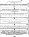
- a particular reception calibration process as illustrated in Fig. 10 is as follows.
- the step 1001 is to start reception calibration.
- the massive BBU transmits the calibration sequence c over the one calibration radio frequency channel, and then receives respectively over the N*M radio frequency channels for reception calibration.
- the massive BBU revises the reception calibration IQ digital signal corresponding to the i -th radio frequency channel into r i / s i according to the reception calibration IQ digital signal corresponding to the i -th radio frequency channel, and the transmission parameter corresponding to the i -th radio frequency channel.
- the massive BBU calculates a reception calibration amplitude revision parameter and a reception calibration phase revision parameter of each radio frequency channel according to the revised reception calibration IQ digital signal, and the calibration sequence.
- the massive BBU receives the uplink data, and then revises the amplitude of the received uplink data according to the reception calibration amplitude revision parameters corresponding to the respective radio frequency channels, and revises the phase of the received uplink data according to the reception calibration phase revision parameters corresponding to the respective radio frequency channels to thereby ensure the amplitude and the phase to be uniform at the respective antenna dipole interfaces.
- a baseband unit converts N*M preset transmission calibration sequences into N*M transmission calibration IQ digital signals, revises the N*M transmission calibration IQ digital signals of corresponding calibration radio frequency channels using N*M preset transmission parameters of the calibration radio frequency channels, and transmits the revised N*M transmission calibration IQ digital signals to an active antenna unit, and the active antenna unit transmits the revised N*M transmission calibration IQ digital signals over N*M radio frequency channels and the one calibration radio frequency channel in that order, and then obtains one transmission calibration IQ digital signal; and, the baseband unit receives the one transmission calibration IQ digital signal, and calculates transmission calibration amplitude revision parameters and transmission calibration phase revision parameters of the respective radio channels corresponding to the calibration radio frequency channels according to the received one transmission calibration IQ digital signal, and the N*M preset transmission calibration sequences.
- the N*M preset transmission parameters of the calibration radio frequency channels are pre-stored in the active antenna unit.
- the baseband unit retrieves the N*M preset transmission parameters of the calibration radio frequency channels from the active antenna unit.
- the baseband unit performs beam-forming on data to be transmitted, revises the amplitude of the beam-formed data using the transmission calibration amplitude revision parameters, revises the phase of the beam-formed data using the transmission calibration phase revision parameters, and then transmits the data to the active antenna unit.
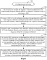
- a particular reception calibration process as illustrated in Fig. 10 is as follows.
- the massive BBU transmits the revised calibration sequences c i s i respectively over the N*M radio frequency channels, and then receives over the one calibration radio frequency channel for transmission calibration.
- the massive BBU receives one mixed transmission calibration IQ digital signal r over the one calibration radio frequency channel, and calculates the transmission calibration amplitude revision parameter and the reception calibration phase revision parameter of each radio frequency channel according to the one mixed transmission calibration IQ digital signal, and the calibration sequence c i corresponding to the radio frequency channel.
- the massive BBU performs beam-forming on the data to be transmitted, revises the amplitude of the beam-formed data according to the transmission calibration amplitude revision parameters, and revises the phase of the beam-formed data according to the transmission calibration phase revision parameters.
- the antenna calibration coupling circuit unit, the calibration radio frequency channel, the primary calibration coupling circuit unit, the transmission and reception calibrating unit, and the calibration parameter storage unit are additionally arranged in the active antenna unit to thereby provide a hardware support for transmission and reception calibration, so that transmission and reception calibration on the respective radio frequency channels can be performed using the active antenna unit including the calibration radio frequency channel and the calibration circuit, and the extensible design of the antenna radio frequency channels can be carried out using the active antenna unit while guaranteeing uniform performance of the respective antenna radio frequency channels to thereby make it less difficult to engineer the array of antennas while guaranteeing the implementation reliability thereof.
- the embodiments of the disclosure can be embodied as a method, a system or a computer program product. Therefore the disclosure can be embodied in the form of an all-hardware embodiment, an all-software embodiment or an embodiment of software and hardware in combination. Furthermore the disclosure can be embodied in the form of a computer program product embodied in one or more computer useable storage mediums (including but not limited to a disk memory, an optical memory, etc.) in which computer useable program codes are contained.
- These computer program instructions can also be stored into a computer readable memory capable of directing the computer or the other programmable data processing device to operate in a specific manner so that the instructions stored in the computer readable memory create an article of manufacture including instruction means which perform the functions specified in the flow(s) of the flow chart and/or the block(s) of the block diagram.
- These computer program instructions can also be loaded onto the computer or the other programmable data processing device so that a series of operational steps are performed on the computer or the other programmable data processing device to create a computer implemented process so that the instructions executed on the computer or the other programmable device provide steps for performing the functions specified in the flow(s) of the flow chart and/or the block(s) of the block diagram
Landscapes
- Engineering & Computer Science (AREA)
- Computer Networks & Wireless Communication (AREA)
- Signal Processing (AREA)
- Physics & Mathematics (AREA)
- Electromagnetism (AREA)
- Power Engineering (AREA)
- Radio Transmission System (AREA)
- Optical Communication System (AREA)
- Variable-Direction Aerials And Aerial Arrays (AREA)
- Transceivers (AREA)
Claims (9)
- Dispositif antenne active (31), caractérisé en ce que le dispositif antenne active (31) comprend :N réseaux d'antennes actives (21), une unité principale formant circuit d'étalonnage et de couplage (302), une unité d'étalonnage d'émission et de réception (303), une unité de stockage de paramètres d'étalonnage (304) et une unité de conversion photoélectrique radio sur fibre (ROF) (301), N étant supérieur à 1 ;chacun des réseaux d'antennes actives (21) comprenant au moins une unité formant circuit d'étalonnage et de couplage d'antenne (205) et M antennes dipôles (204) connectées à l'unité formant circuit d'étalonnage et de couplage d'antenne (205), M étant supérieur à 1 ;les unités formant circuit d'étalonnage et de couplage d'antenne (205) des réseaux d'antennes actives (21) étant connectées à l'unité principale formant circuit d'étalonnage et de couplage (302) sur un canal radioélectrique d'étalonnage, l'unité principale formant circuit d'étalonnage et de couplage (302) étant connectée à l'unité d'étalonnage d'émission et de réception (303), et l'unité d'étalonnage d'émission et de réception (303) et l'unité de stockage de paramètres d'étalonnage (304) étant connectées respectivement à l'unité de conversion photoélectrique ROF (301) ;l'unité de stockage de paramètres d'étalonnage (304) étant configurée pour stocker des paramètres d'émission des canaux radioélectriques d'étalonnage des N réseaux d'antennes actives (21) et pour émettre les paramètres d'émission vers l'unité de conversion photoélectrique ROF (301) ; l'unité de conversion photoélectrique ROF (301) étant configurée pour convertir les paramètres d'émission en un signal optique et pour émettre le signal optique sur une fibre optique ; etl'unité formant circuit d'étalonnage et de couplage d'antenne (205) de chaque réseau d'antennes actives étant configurée pour coupler M signaux radioélectriques d'étalonnage reçus en un signal radioélectrique d'étalonnage d'émission et pour émettre ledit signal radioélectrique d'étalonnage d'émission vers l'unité principale formant circuit d'étalonnage et de couplage (302) sur le canal radioélectrique d'étalonnage ; l'unité principale formant circuit d'étalonnage et de couplage (302) étant configurée pour fusionner les N signaux radioélectriques d'étalonnage d'émission émis par les N réseaux de d'antennes actives en un signal radioélectrique d'étalonnage d'émission ; l'unité d'étalonnage d'émission et de réception (303) étant configurée pour amplifier la puissance dudit signal radioélectrique d'étalonnage d'émission émis par l'unité principale formant circuit d'étalonnage et de couplage (302), puis pour démoduler ledit signal radioélectrique d'étalonnage d'émission en un signal analogique en phase et en quadrature de phase (IQ) d'étalonnage d'émission et pour produire le signal analogique IQ d'étalonnage d'émission vers l'unité de conversion photoélectrique ROF (301) ; et l'unité de conversion photoélectrique ROF (301) étant configurée pour convertir le signal analogique IQ d'étalonnage d'émission en un signal optique et pour émettre le signal optique sur la fibre optique ; et/oul'unité d'étalonnage d'émission et de réception (303) étant configurée pour moduler un signal analogique IQ d'étalonnage de réception émis par l'unité de conversion photoélectrique ROF (301) en un signal radioélectrique d'étalonnage de réception, pour amplifier la puissance du signal radioélectrique d'étalonnage de réception, puis pour émettre le signal radioélectrique d'étalonnage de réception amplifié en puissance vers l'unité principale formant circuit d'étalonnage et de couplage (302) ; l'unité principale formant circuit d'étalonnage et de couplage (302) étant configurée pour séparer le signal radioélectrique d'étalonnage de réception amplifié en puissance en N signaux radioélectriques d'étalonnage de réception dupliqués et pour émettre respectivement les N signaux radioélectriques d'étalonnage de réception dupliqués vers les unités formant circuit d'étalonnage et de couplage d'antenne (205) correspondantes sur le canal radioélectrique d'étalonnage correspondant aux N réseaux d'antennes actives (21) ; et chaque unité formant circuit d'étalonnage et de couplage d'antenne (205) étant configurée pour séparer ledit signal radioélectrique d'étalonnage de réception reçu en M signaux radioélectriques d'étalonnage de réception.
- Dispositif antenne active (31) selon la revendication 1, dans lequel chaque réseau d'antennes actives (21) comprend en outre :un réseau de filtres (201), un réseau d'amplificateurs de puissance (PA) et d'amplificateurs à faible bruit (LNA) (202) et un réseau d'émetteurs-récepteurs (203), le réseau de filtres (201), le réseau de PA et de LNA (202) et le réseau d'émetteurs-récepteurs (203) étant connectés en séquence, le réseau de filtres (201) étant connecté à l'unité formant circuit d'étalonnage et de couplage d'antenne (205) et le réseau d'émetteurs-récepteurs (203) étant connecté à l'unité de conversion photoélectrique ROF (301) ;le réseau de filtres (201) étant configuré pour filtrer les M signaux radioélectriques d'étalonnage d'émission ou les M signaux radioélectriques d'étalonnage de réception ;le réseau de PA et de LNA (202) étant configuré pour amplifier la puissance des M signaux radioélectriques d'étalonnage d'émission ou des M signaux radioélectriques d'étalonnage de réception ; etle réseau d'émetteurs-récepteurs (203) étant configuré pour convertir les M signaux radioélectriques d'étalonnage d'émission ou les M signaux radioélectriques d'étalonnage de réception en M signaux analogiques IQ et pour émettre les M signaux analogiques IQ ; ou pour convertir M signaux analogiques IQ reçus en les M signaux radioélectriques d'étalonnage d'émission ou en les M signaux radioélectriques d'étalonnage de réception.
- Dispositif antenne active (31) selon la revendication 1, dans lequel l'unité principale formant circuit d'étalonnage et de couplage (302) comprend :plusieurs fusionneurs-séparateurs ; ouplusieurs fusionneurs-séparateurs ou plusieurs coupleurs ; ouplusieurs matrices de commutateurs.
- Dispositif antenne active (31) selon la revendication 2, dans lequel l'unité d'étalonnage d'émission et de réception (303) comprend une unité d'amplification de signal radioélectrique (401) et une unité émettrice-réceptrice (402), l'unité d'amplification de signal radioélectrique (401) et l'unité émettrice-réceptrice (402) étant connectées l'une à l'autre ;
l'unité d'amplification de signal radioélectrique (401) étant connectée à l'unité principale formant circuit d'étalonnage et de couplage (302) et l'unité émettrice-réceptrice (402) étant connectée à l'unité de conversion photoélectrique ROF (301) ; ou
chaque réseau de filtres (201) comprenant M filtres indépendants les uns des autres ; ou
chaque réseau de PA et de LNA (202) comprenant M amplificateurs de puissance indépendants les uns des autres et M amplificateurs à faible bruit indépendants les uns des autres ; ou
chaque réseau d'émetteurs-récepteurs (203) comprenant M unités émettrices-réceptrices (402). - Dispositif antenne active (51), caractérisé en ce que le dispositif antenne active (51) comprend :N réseaux d'antennes actives (21), une unité principale formant circuit d'étalonnage et de couplage (503), une unité d'étalonnage d'émission et de réception (504), une unité de stockage de paramètres d'étalonnage (505) une unité de traitement numérique (501) et une unité formant interface numérique à fibre optique (502), N étant supérieur à 1 ;chacun des réseaux d'antennes actives (21) comprenant au moins une unité formant circuit d'étalonnage et de couplage d'antenne (205) et M antennes dipôles (204) connectées à l'unité formant circuit d'étalonnage et de couplage d'antenne (205), M étant supérieur à 1 ;les unités formant circuit d'étalonnage et de couplage d'antenne (205) des réseaux d'antennes actives (21) étant connectées à l'unité principale formant circuit d'étalonnage et de couplage (503) sur un canal radioélectrique d'étalonnage, l'unité principale formant circuit d'étalonnage et de couplage (503) étant connectée à l'unité d'étalonnage d'émission et de réception (504), et l'unité d'étalonnage d'émission et de réception (504) et l'unité de stockage de paramètres d'étalonnage (505) étant connectées respectivement à l'unité de traitement numérique (501) ;l'unité de stockage de paramètres d'étalonnage (505) étant configurée pour stocker des paramètres d'émission du canal radioélectrique d'étalonnage des N réseaux d'antennes actives (21) et pour émettre les paramètres d'émission vers l'unité de traitement numérique (501) ; etl'unité formant circuit d'étalonnage et de couplage d'antenne (205) de chaque réseau d'antennes actives étant configurée pour coupler M signaux radioélectriques d'étalonnage reçus en un signal radioélectrique d'étalonnage d'émission et pour émettre ledit signal radioélectrique d'étalonnage d'émission vers l'unité principale formant circuit d'étalonnage et de couplage (503) sur le canal radioélectrique d'étalonnage ; l'unité principale formant circuit d'étalonnage et de couplage (503) étant configurée pour fusionner les N signaux radioélectriques d'étalonnage d'émission émis par les N réseaux de d'antennes actives en un signal radioélectrique d'étalonnage d'émission ; l'unité d'étalonnage d'émission et de réception (504) étant configurée pour amplifier la puissance dudit signal radioélectrique d'étalonnage d'émission émis par l'unité principale formant circuit d'étalonnage et de couplage (503), puis pour démoduler ledit signal radioélectrique d'étalonnage d'émission en un signal analogique en phase et en quadrature de phase (IQ) d'étalonnage d'émission et pour produire le signal analogique IQ d'étalonnage d'émission vers l'unité de traitement numérique (501) ; et l'unité de traitement numérique (501) étant configurée pour convertir le signal analogique IQ d'étalonnage d'émission en un signal numérique IQ d'étalonnage d'émission et pour émettre le signal numérique IQ d'étalonnage d'émission par l'intermédiaire de l'unité formant interface numérique à fibre optique (502) ; et/oul'unité de traitement numérique (501) étant configurée pour convertir un signal numérique IQ d'étalonnage de réception reçu par l'unité formant interface numérique à fibre optique (502) en un signal analogique IQ d'étalonnage de réception ; l'unité d'étalonnage d'émission et de réception (504) étant configurée pour moduler le signal analogique IQ d'étalonnage de réception émis par l'unité de traitement numérique (501) en un signal radioélectrique d'étalonnage de réception, pour amplifier la puissance du signal radioélectrique d'étalonnage de réception, puis pour émettre le signal radioélectrique d'étalonnage de réception amplifié en puissance vers l'unité principale formant circuit d'étalonnage et de couplage (503) ; l'unité principale formant circuit d'étalonnage et de couplage (503) étant configurée pour séparer le signal radioélectrique d'étalonnage de réception amplifié en puissance en N signaux radioélectriques d'étalonnage de réception dupliqués et pour émettre respectivement les N signaux radioélectriques d'étalonnage de réception dupliqués vers les unités formant circuit d'étalonnage et de couplage d'antenne (205) correspondantes sur le canal radioélectrique d'étalonnage correspondant aux N réseaux d'antennes actives (21) ; et chaque unité formant circuit d'étalonnage et de couplage d'antenne (205) étant configurée pour séparer ledit signal radioélectrique d'étalonnage de réception reçu en M signaux radioélectriques d'étalonnage de réception.
- Dispositif antenne active (51) selon la revendication 5, dans lequel chaque réseau d'antennes actives (21) comprend en outre :un réseau de filtres (201), un réseau d'amplificateurs de puissance (PA) et d'amplificateurs à faible bruit (LNA) (202) et un réseau d'émetteurs-récepteurs (203), le réseau de filtres (201), le réseau de PA et de LNA et le réseau d'émetteurs-récepteurs étant connectés en séquence, le réseau de filtres (201) étant connecté à l'unité formant circuit d'étalonnage et de couplage d'antenne (205) et le réseau d'émetteurs-récepteurs (203) étant connecté à l'unité de traitement numérique (501) ;le réseau de filtres (201) étant configuré pour filtrer les M signaux radioélectriques d'étalonnage d'émission ou les M signaux radioélectriques d'étalonnage de réception ;le réseau de PA et de LNA (202) étant configuré pour amplifier la puissance des M signaux radioélectriques d'étalonnage d'émission ou des M signaux radioélectriques d'étalonnage de réception ; etle réseau d'émetteurs-récepteurs (203) étant configuré pour convertir les M signaux radioélectriques d'étalonnage d'émission ou les M signaux radioélectriques d'étalonnage de réception en M signaux analogiques IQ et pour émettre les M signaux analogiques IQ ; ou pour convertir M signaux analogiques IQ reçus en les M signaux radioélectriques d'étalonnage d'émission ou en les M signaux radioélectriques d'étalonnage de réception ; oul'unité principale formant circuit d'étalonnage et de couplage (503) comprenant :plusieurs fusionneurs-séparateurs ; ouplusieurs fusionneurs-séparateurs ou plusieurs coupleurs ; ouplusieurs matrices de commutateurs.
- Dispositif antenne active (51) selon la revendication 6, dans lequel l'unité d'étalonnage d'émission et de réception (504) comprend une unité d'amplification de signal radioélectrique et une unité émettrice-réceptrice, l'unité d'amplification de signal radioélectrique et l'unité émettrice-réceptrice étant connectées l'une à l'autre, et dans lequel :
l'unité d'amplification de signal radioélectrique est connectée à l'unité principale formant circuit d'étalonnage et de couplage (503) et l'unité émettrice-réceptrice est connectée à l'unité de traitement numérique (501). - Système de communication, le système de communication étant caractérisé en ce qu'il comprend le dispositif antenne active (51) selon l'une quelconque des revendications 5 à 7 et un dispositif de génération de bande de base (71), le dispositif antenne active (51) et le dispositif de génération de bande de base (71) étant connectés sur une fibre optique et le dispositif de génération de bande de base (71) comprenant une unité formant interface numérique à fibre optique (701) et une unité en bande de base (702), l'unité formant interface numérique à fibre optique (701) et l'unité en bande de base (702) étant connectées l'une à l'autre ;
l'unité en bande de base (702) étant configurée pour convertir une séquence prédéfinie d'étalonnage de réception en un signal numérique IQ d'étalonnage de réception et pour émettre ledit signal numérique IQ d'étalonnage de réception vers l'unité formant interface numérique à fibre optique (701), et l'unité formant interface numérique à fibre optique (701) étant configurée pour émettre ledit signal numérique IQ d'étalonnage de réception sur la fibre optique ; et l'unité en bande de base (702) étant configurée pour recevoir N*M signaux numériques IQ d'étalonnage de réception émis par l'unité formant interface numérique à fibre optique (701), pour réviser les N*M signaux numériques IQ d'étalonnage de réception au moyen de paramètres d'émission prédéfinis de N*M canaux radioélectriques d'étalonnage, et pour calculer des paramètres de révision d'amplitude d'étalonnage de réception et des paramètres de révision de phase d'étalonnage de réception correspondant à des canaux radioélectriques respectifs correspondant aux N*M canaux radioélectriques d'étalonnage selon les N*M signaux numériques IQ d'étalonnage de réception révisés et ladite séquence prédéfinie d'étalonnage de réception ; et/ou
l'unité en bande de base (702) étant configurée pour convertir N*M séquences prédéfinies d'étalonnage d'émission en N*M signaux numériques IQ d'étalonnage d'émission, pour réviser les N*M signaux numériques IQ d'étalonnage d'émission au moyen des paramètres d'émission prédéfinis des N*M canaux radioélectriques d'émission, et pour émettre les N*M signaux numériques IQ d'étalonnage d'émission révisés vers l'unité formant interface numérique à fibre optique (701), et l'unité formant interface numérique à fibre optique (701) étant configurée pour convertir les N*M signaux numériques IQ d'étalonnage d'émission révisés en un signal optique et pour émettre le signal optique sur la fibre optique ; et l'unité en bande de base (702) étant configurée pour recevoir un signal numérique IQ d'étalonnage d'émission émis par l'unité formant interface numérique à fibre optique (701) et pour calculer des paramètres de révision d'amplitude d'étalonnage d'émission et des paramètres de révision de phase d'étalonnage d'émission des canaux radioélectriques respectifs correspondant aux N*M canaux radioélectriques d'étalonnage selon ledit signal numérique IQ d'étalonnage d'émission reçu et les N*M séquences prédéfinies d'étalonnage d'émission ;
les N*M signaux numériques IQ d'étalonnage de réception reçus étant des signaux obtenus après que ledit signal numérique IQ d'étalonnage de réception a été émis d'abord sur un canal radioélectrique d'étalonnage du dispositif antenne active (51) puis sur N*M canaux radioélectriques du dispositif antenne active (51), puis reçu sur la fibre optique et traité par l'unité formant interface numérique à fibre optique (701) ;
ledit signal numérique IQ d'étalonnage d'émission reçu étant un signal obtenu après que les N*M signaux numériques IQ d'étalonnage d'émission révisés ont été émis d'abord sur les N*M canaux radioélectriques du dispositif antenne active (51) puis sur le canal radioélectrique d'étalonnage du dispositif antenne active (51), puis reçus sur la fibre optique et traités par l'unité formant interface numérique à fibre optique (701) ; et
les paramètres d'émission prédéfinis des N*M canaux radioélectriques d'étalonnage étant reçus sur la fibre optique, puis émis par l'unité formant interface numérique à fibre optique (701) vers l'unité en bande de base (702). - Système de communication selon la revendication 8, dans lequel :l'unité en bande de base (702) est en outre configurée pour :
obtenir des données en liaison montante, réviser l'amplitude des données en liaison montante au moyen des paramètres de révision d'amplitude d'étalonnage de réception, et réviser la phase des données en liaison montante au moyen des paramètres de révision de phase d'étalonnage de réception ; etles données en liaison montante étant obtenues à la suite de la réception d'un signal en liaison montante sur la fibre optique et de son émission par l'unité formant interface numérique à fibre optique (701) vers l'unité en bande de base (702) ; oul'unité en bande de base (702) est en outre configurée pour :
réaliser une formation de faisceau sur des données à émettre, réviser l'amplitude des données à faisceau conformé au moyen des paramètres de révision d'amplitude d'étalonnage d'émission, réviser la phase des données à faisceau conformé au moyen des paramètres de révision de phase d'étalonnage d'émission, puis émettre les données vers l'unité formant interface numérique à fibre optique (701), de sorte que l'unité formant interface numérique à fibre optique (701) convertisse les données en un signal optique, puis émette le signal optique sur la fibre optique.
Applications Claiming Priority (2)
| Application Number | Priority Date | Filing Date | Title |
|---|---|---|---|
| CN201410204038.0A CN103997352B (zh) | 2014-05-14 | 2014-05-14 | 有源天线相关设备、系统及收发校准方法 |
| PCT/CN2015/078979 WO2015172730A1 (fr) | 2014-05-14 | 2015-05-14 | Dispositif d'antenne active et système associé, et procédé d'étalonnage d'émission et de réception |
Publications (3)
| Publication Number | Publication Date |
|---|---|
| EP3145090A1 EP3145090A1 (fr) | 2017-03-22 |
| EP3145090A4 EP3145090A4 (fr) | 2017-06-21 |
| EP3145090B1 true EP3145090B1 (fr) | 2020-09-09 |
Family
ID=51311373
Family Applications (1)
| Application Number | Title | Priority Date | Filing Date |
|---|---|---|---|
| EP15792998.5A Active EP3145090B1 (fr) | 2014-05-14 | 2015-05-14 | Dispositif d'antenne active, système de communication, et procédé d'étalonnage d'émission et de réception |
Country Status (4)
| Country | Link |
|---|---|
| US (1) | US10305183B2 (fr) |
| EP (1) | EP3145090B1 (fr) |
| CN (1) | CN103997352B (fr) |
| WO (1) | WO2015172730A1 (fr) |
Families Citing this family (27)
| Publication number | Priority date | Publication date | Assignee | Title |
|---|---|---|---|---|
| CN103997352B (zh) * | 2014-05-14 | 2016-02-24 | 电信科学技术研究院 | 有源天线相关设备、系统及收发校准方法 |
| CN105049102A (zh) * | 2015-08-07 | 2015-11-11 | 苏州市吴通天线有限公司 | 一种高频率毫米波集成天线系统 |
| CN106877944B (zh) | 2015-12-10 | 2019-07-19 | 电信科学技术研究院 | 一种有源天线设备及其测试方法 |
| CN106452541B (zh) * | 2016-07-19 | 2020-01-07 | 北京邮电大学 | 一种光和无线信号相互辅助的波束赋形方法和装置 |
| CN106680601A (zh) * | 2016-11-25 | 2017-05-17 | 上海华为技术有限公司 | 一种信号处理的方法、有源天线及信号处理系统 |
| WO2018133065A1 (fr) * | 2017-01-22 | 2018-07-26 | 华为技术有限公司 | Dispositif de commutation de port d'antenne et unité d'antenne active |
| WO2019061147A1 (fr) * | 2017-09-28 | 2019-04-04 | Telefonaktiebolaget Lm Ericsson (Publ) | Station de base et procédé pour faciliter l'étalonnage d'émetteurs-récepteurs radio sur fibre |
| WO2020006748A1 (fr) | 2018-07-06 | 2020-01-09 | 华为技术有限公司 | Procédé destiné à étalonner une antenne de réseau équiphase, et appareil associé |
| FR3087977B1 (fr) * | 2018-10-29 | 2021-12-10 | Safran Electronics & Defense | Auto-etalonnage d'un reseau d'antennes |
| CN109347492B (zh) * | 2018-10-31 | 2021-03-26 | 鹰视云(深圳)科技有限公司 | 一种增强移动通信基站空天覆盖能力的系统及方法 |
| CN111510229B (zh) * | 2019-01-30 | 2022-12-27 | 华为技术有限公司 | 射频通道的校正方法和装置及天线和基站 |
| CN111726172B (zh) | 2019-03-22 | 2021-10-26 | 华为技术有限公司 | 通道校正的方法和装置 |
| CN110212986A (zh) * | 2019-06-13 | 2019-09-06 | 苏州市职业大学 | 一种基于合波传输的5g光信号前传架构 |
| US11482779B2 (en) | 2019-07-12 | 2022-10-25 | Raytheon Company | Minimal phase matched test target injection for parallel receiver phase and amplitude alignment |
| JP7416915B2 (ja) * | 2019-08-30 | 2024-01-17 | 華為技術有限公司 | アンテナ較正装置およびアンテナ較正方法 |
| CN112825503B (zh) * | 2019-11-20 | 2022-03-25 | 大唐移动通信设备有限公司 | 一种链路调度方法及设备 |
| CN111193560B (zh) * | 2020-01-06 | 2021-10-15 | 西南电子技术研究所(中国电子科技集团公司第十研究所) | 多目标测控通信天线阵列光纤闭环校准方法 |
| CN113660713A (zh) * | 2020-05-12 | 2021-11-16 | 大唐移动通信设备有限公司 | 一种有源天线处理单元、工作状态的切换方法及装置 |
| CN112040487A (zh) * | 2020-07-15 | 2020-12-04 | 中国电子科技集团公司第三十研究所 | 一种多优先级高效的5g网络数据服务安全通道管理方法 |
| CN114039287A (zh) * | 2020-09-03 | 2022-02-11 | 无锡专心智制科技有限公司 | 一种智能电源时序管理器 |
| WO2022133824A1 (fr) * | 2020-12-23 | 2022-06-30 | 华为技术有限公司 | Procédé et appareil de communication sans fil |
| CN112994808B (zh) * | 2021-05-20 | 2021-07-27 | 成都天锐星通科技有限公司 | 一种射频信号内校准系统及相控阵天线 |
| CN113451776B (zh) * | 2021-06-22 | 2024-03-26 | 广州中雷电科科技有限公司 | 一种高集成度数字相控阵系统 |
| CN113452789B (zh) * | 2021-06-29 | 2022-07-01 | 中信科移动通信技术股份有限公司 | 一种前传接口频域合路系统及频域合路方法 |
| CN114389029B (zh) * | 2021-12-31 | 2025-07-15 | 北京无线电计量测试研究所 | 一种多模块综合实现天线阵列参数快速切换的方法 |
| CN114567393B (zh) * | 2022-03-10 | 2023-07-11 | 四川恒湾科技有限公司 | 一种射频拉远单元下行链路自检测方法 |
| CN115941012B (zh) * | 2023-03-15 | 2023-05-12 | 电子科技大学 | 芯片化可重构弹性规模多波束数字阵列 |
Family Cites Families (22)
| Publication number | Priority date | Publication date | Assignee | Title |
|---|---|---|---|---|
| US6075997A (en) * | 1997-11-03 | 2000-06-13 | Telefonaktiebolaget L M Ericsson (Publ) | Automatic configuration of antenna near parts equipment |
| JP3347099B2 (ja) * | 1999-07-23 | 2002-11-20 | エヌイーシーアクセステクニカ株式会社 | 簡易携帯電話内蔵型携帯電話機におけるアンテナ切替回路 |
| US7233285B2 (en) | 2003-03-20 | 2007-06-19 | Bae Systems Information And Electronic Systems Integration Inc. | Correlation interferometer geolocation |
| US7676210B2 (en) * | 2003-09-29 | 2010-03-09 | Tod Paulus | Method for performing dual mode image rejection calibration in a receiver |
| GB0513583D0 (en) * | 2005-07-01 | 2005-08-10 | Nokia Corp | A mobile communications network with multiple radio units |
| EP1746735A1 (fr) * | 2005-07-20 | 2007-01-24 | Sony Ericsson Mobile Communications AB | Appareil et procédé pour contrôle d'antenne |
| US8320903B2 (en) | 2005-09-07 | 2012-11-27 | Samsung Electronics Co., Ltd. | Method and system for calibrating multiple types of base stations in a wireless network |
| GB0616449D0 (en) * | 2006-08-18 | 2006-09-27 | Quintel Technology Ltd | Diversity antenna system with electrical tilt |
| JP2008219453A (ja) * | 2007-03-05 | 2008-09-18 | Alps Electric Co Ltd | 送受信回路モジュール |
| KR20080093746A (ko) * | 2007-04-18 | 2008-10-22 | 삼성전자주식회사 | 저잡음 증폭기를 상하향 공용으로 구성하는 시분할 이중화방식의 원격 스테이션 및 이를 이용한 유선 중계 방법 |
| CN101383647B (zh) * | 2007-09-06 | 2012-01-11 | 电信科学技术研究院 | 对工作天线进行校准的方法及装置 |
| CN101651480B (zh) | 2008-08-14 | 2013-04-24 | 华为技术有限公司 | 有源天线、基站、刷新幅度和相位的方法及信号处理方法 |
| CN102308437B (zh) * | 2009-05-26 | 2013-09-11 | 华为技术有限公司 | 一种天线装置 |
| US20100321233A1 (en) | 2009-06-18 | 2010-12-23 | Alvarion Ltd. | Method for calibrating antenna arrays |
| US8599861B2 (en) * | 2010-06-03 | 2013-12-03 | Kathrein-Werke Kg | Active antenna array and method for relaying radio signals |
| CN102377027A (zh) * | 2010-08-27 | 2012-03-14 | 大唐移动通信设备有限公司 | 一种有源天线及校准有源天线的方法 |
| CN102035611B (zh) | 2010-12-29 | 2014-03-12 | 武汉邮电科学研究院 | 远端射频单元多天线实时校准系统及其方法 |
| US20130260844A1 (en) | 2012-03-28 | 2013-10-03 | Andrew Llc | Series-connected couplers for active antenna systems |
| CN102857310B (zh) * | 2012-07-27 | 2017-10-27 | 中兴通讯股份有限公司 | 一种有源天线系统无线指标的测试方法及装置 |
| CN103338084B (zh) * | 2013-06-14 | 2015-04-22 | 三维通信股份有限公司 | 一种基于rof的新型基站反馈接收、收发校准复用电路 |
| CN203387519U (zh) * | 2013-06-14 | 2014-01-08 | 三维通信股份有限公司 | 基于rof的新型基站反馈接收、收发校准复用电路 |
| CN103997352B (zh) | 2014-05-14 | 2016-02-24 | 电信科学技术研究院 | 有源天线相关设备、系统及收发校准方法 |
-
2014
- 2014-05-14 CN CN201410204038.0A patent/CN103997352B/zh active Active
-
2015
- 2015-05-14 EP EP15792998.5A patent/EP3145090B1/fr active Active
- 2015-05-14 WO PCT/CN2015/078979 patent/WO2015172730A1/fr not_active Ceased
- 2015-05-14 US US15/310,702 patent/US10305183B2/en active Active
Non-Patent Citations (1)
| Title |
|---|
| None * |
Also Published As
| Publication number | Publication date |
|---|---|
| US20170077602A1 (en) | 2017-03-16 |
| EP3145090A4 (fr) | 2017-06-21 |
| CN103997352B (zh) | 2016-02-24 |
| EP3145090A1 (fr) | 2017-03-22 |
| US10305183B2 (en) | 2019-05-28 |
| CN103997352A (zh) | 2014-08-20 |
| WO2015172730A1 (fr) | 2015-11-19 |
Similar Documents
| Publication | Publication Date | Title |
|---|---|---|
| EP3145090B1 (fr) | Dispositif d'antenne active, système de communication, et procédé d'étalonnage d'émission et de réception | |
| US10601378B2 (en) | Distributed antenna system architectures | |
| US8694034B2 (en) | System and method for the distribution of radio-frequency signals | |
| CN101651480B (zh) | 有源天线、基站、刷新幅度和相位的方法及信号处理方法 | |
| US10122476B2 (en) | Radio unit with internal parallel antenna calibration | |
| EP2775681B1 (fr) | Procédé, dispositif et système de station de base d'émission-réception et de traitement de signal radiofréquence | |
| EP2845322B1 (fr) | Appareil et procédé de radiocommunication | |
| KR102116539B1 (ko) | 원격 무선 장비 | |
| EP2847867B1 (fr) | Appareil émetteur de radiocommunication et procédé correspondant | |
| US10516492B2 (en) | Remote apparatus of distributed antenna system | |
| KR102165072B1 (ko) | 분산 안테나 시스템 및 이의 리모트 장치 | |
| US10536227B2 (en) | Active antenna device and test method therefor | |
| US20150111504A1 (en) | Calibration coupleing unit, ccu, and a method therein for enabling calibration of base station | |
| CN110800160A (zh) | 天线系统、基站以及通信系统 | |
| KR20160048557A (ko) | Rf 트랜시버 어레이를 이용하여 sdr을 구현하는 무선 송수신 시스템 및 방법 | |
| WO2015034313A1 (fr) | Tête radio distante |
Legal Events
| Date | Code | Title | Description |
|---|---|---|---|
| STAA | Information on the status of an ep patent application or granted ep patent |
Free format text: STATUS: THE INTERNATIONAL PUBLICATION HAS BEEN MADE |
|
| PUAI | Public reference made under article 153(3) epc to a published international application that has entered the european phase |
Free format text: ORIGINAL CODE: 0009012 |
|
| STAA | Information on the status of an ep patent application or granted ep patent |
Free format text: STATUS: REQUEST FOR EXAMINATION WAS MADE |
|
| 17P | Request for examination filed |
Effective date: 20161130 |
|
| AK | Designated contracting states |
Kind code of ref document: A1 Designated state(s): AL AT BE BG CH CY CZ DE DK EE ES FI FR GB GR HR HU IE IS IT LI LT LU LV MC MK MT NL NO PL PT RO RS SE SI SK SM TR |
|
| AX | Request for extension of the european patent |
Extension state: BA ME |
|
| A4 | Supplementary search report drawn up and despatched |
Effective date: 20170519 |
|
| RIC1 | Information provided on ipc code assigned before grant |
Ipc: H04B 17/11 20150101ALI20170515BHEP Ipc: H04B 1/10 20060101AFI20170515BHEP |
|
| DAV | Request for validation of the european patent (deleted) | ||
| DAX | Request for extension of the european patent (deleted) | ||
| STAA | Information on the status of an ep patent application or granted ep patent |
Free format text: STATUS: EXAMINATION IS IN PROGRESS |
|
| 17Q | First examination report despatched |
Effective date: 20180619 |
|
| GRAP | Despatch of communication of intention to grant a patent |
Free format text: ORIGINAL CODE: EPIDOSNIGR1 |
|
| STAA | Information on the status of an ep patent application or granted ep patent |
Free format text: STATUS: GRANT OF PATENT IS INTENDED |
|
| INTG | Intention to grant announced |
Effective date: 20200423 |
|
| GRAS | Grant fee paid |
Free format text: ORIGINAL CODE: EPIDOSNIGR3 |
|
| GRAA | (expected) grant |
Free format text: ORIGINAL CODE: 0009210 |
|
| STAA | Information on the status of an ep patent application or granted ep patent |
Free format text: STATUS: THE PATENT HAS BEEN GRANTED |
|
| AK | Designated contracting states |
Kind code of ref document: B1 Designated state(s): AL AT BE BG CH CY CZ DE DK EE ES FI FR GB GR HR HU IE IS IT LI LT LU LV MC MK MT NL NO PL PT RO RS SE SI SK SM TR |
|
| REG | Reference to a national code |
Ref country code: GB Ref legal event code: FG4D |
|
| REG | Reference to a national code |
Ref country code: AT Ref legal event code: REF Ref document number: 1312838 Country of ref document: AT Kind code of ref document: T Effective date: 20200915 Ref country code: CH Ref legal event code: EP |
|
| REG | Reference to a national code |
Ref country code: IE Ref legal event code: FG4D |
|
| REG | Reference to a national code |
Ref country code: DE Ref legal event code: R096 Ref document number: 602015058857 Country of ref document: DE |
|
| REG | Reference to a national code |
Ref country code: LT Ref legal event code: MG4D |
|
| PG25 | Lapsed in a contracting state [announced via postgrant information from national office to epo] |
Ref country code: FI Free format text: LAPSE BECAUSE OF FAILURE TO SUBMIT A TRANSLATION OF THE DESCRIPTION OR TO PAY THE FEE WITHIN THE PRESCRIBED TIME-LIMIT Effective date: 20200909 Ref country code: NO Free format text: LAPSE BECAUSE OF FAILURE TO SUBMIT A TRANSLATION OF THE DESCRIPTION OR TO PAY THE FEE WITHIN THE PRESCRIBED TIME-LIMIT Effective date: 20201209 Ref country code: BG Free format text: LAPSE BECAUSE OF FAILURE TO SUBMIT A TRANSLATION OF THE DESCRIPTION OR TO PAY THE FEE WITHIN THE PRESCRIBED TIME-LIMIT Effective date: 20201209 Ref country code: SE Free format text: LAPSE BECAUSE OF FAILURE TO SUBMIT A TRANSLATION OF THE DESCRIPTION OR TO PAY THE FEE WITHIN THE PRESCRIBED TIME-LIMIT Effective date: 20200909 Ref country code: HR Free format text: LAPSE BECAUSE OF FAILURE TO SUBMIT A TRANSLATION OF THE DESCRIPTION OR TO PAY THE FEE WITHIN THE PRESCRIBED TIME-LIMIT Effective date: 20200909 Ref country code: LT Free format text: LAPSE BECAUSE OF FAILURE TO SUBMIT A TRANSLATION OF THE DESCRIPTION OR TO PAY THE FEE WITHIN THE PRESCRIBED TIME-LIMIT Effective date: 20200909 Ref country code: GR Free format text: LAPSE BECAUSE OF FAILURE TO SUBMIT A TRANSLATION OF THE DESCRIPTION OR TO PAY THE FEE WITHIN THE PRESCRIBED TIME-LIMIT Effective date: 20201210 |
|
| REG | Reference to a national code |
Ref country code: AT Ref legal event code: MK05 Ref document number: 1312838 Country of ref document: AT Kind code of ref document: T Effective date: 20200909 |
|
| REG | Reference to a national code |
Ref country code: NL Ref legal event code: MP Effective date: 20200909 |
|
| PG25 | Lapsed in a contracting state [announced via postgrant information from national office to epo] |
Ref country code: LV Free format text: LAPSE BECAUSE OF FAILURE TO SUBMIT A TRANSLATION OF THE DESCRIPTION OR TO PAY THE FEE WITHIN THE PRESCRIBED TIME-LIMIT Effective date: 20200909 Ref country code: RS Free format text: LAPSE BECAUSE OF FAILURE TO SUBMIT A TRANSLATION OF THE DESCRIPTION OR TO PAY THE FEE WITHIN THE PRESCRIBED TIME-LIMIT Effective date: 20200909 Ref country code: PL Free format text: LAPSE BECAUSE OF FAILURE TO SUBMIT A TRANSLATION OF THE DESCRIPTION OR TO PAY THE FEE WITHIN THE PRESCRIBED TIME-LIMIT Effective date: 20200909 |
|
| PG25 | Lapsed in a contracting state [announced via postgrant information from national office to epo] |
Ref country code: NL Free format text: LAPSE BECAUSE OF FAILURE TO SUBMIT A TRANSLATION OF THE DESCRIPTION OR TO PAY THE FEE WITHIN THE PRESCRIBED TIME-LIMIT Effective date: 20200909 Ref country code: SM Free format text: LAPSE BECAUSE OF FAILURE TO SUBMIT A TRANSLATION OF THE DESCRIPTION OR TO PAY THE FEE WITHIN THE PRESCRIBED TIME-LIMIT Effective date: 20200909 Ref country code: PT Free format text: LAPSE BECAUSE OF FAILURE TO SUBMIT A TRANSLATION OF THE DESCRIPTION OR TO PAY THE FEE WITHIN THE PRESCRIBED TIME-LIMIT Effective date: 20210111 Ref country code: RO Free format text: LAPSE BECAUSE OF FAILURE TO SUBMIT A TRANSLATION OF THE DESCRIPTION OR TO PAY THE FEE WITHIN THE PRESCRIBED TIME-LIMIT Effective date: 20200909 Ref country code: EE Free format text: LAPSE BECAUSE OF FAILURE TO SUBMIT A TRANSLATION OF THE DESCRIPTION OR TO PAY THE FEE WITHIN THE PRESCRIBED TIME-LIMIT Effective date: 20200909 Ref country code: CZ Free format text: LAPSE BECAUSE OF FAILURE TO SUBMIT A TRANSLATION OF THE DESCRIPTION OR TO PAY THE FEE WITHIN THE PRESCRIBED TIME-LIMIT Effective date: 20200909 |
|
| PG25 | Lapsed in a contracting state [announced via postgrant information from national office to epo] |
Ref country code: IS Free format text: LAPSE BECAUSE OF FAILURE TO SUBMIT A TRANSLATION OF THE DESCRIPTION OR TO PAY THE FEE WITHIN THE PRESCRIBED TIME-LIMIT Effective date: 20210109 Ref country code: ES Free format text: LAPSE BECAUSE OF FAILURE TO SUBMIT A TRANSLATION OF THE DESCRIPTION OR TO PAY THE FEE WITHIN THE PRESCRIBED TIME-LIMIT Effective date: 20200909 Ref country code: AT Free format text: LAPSE BECAUSE OF FAILURE TO SUBMIT A TRANSLATION OF THE DESCRIPTION OR TO PAY THE FEE WITHIN THE PRESCRIBED TIME-LIMIT Effective date: 20200909 Ref country code: AL Free format text: LAPSE BECAUSE OF FAILURE TO SUBMIT A TRANSLATION OF THE DESCRIPTION OR TO PAY THE FEE WITHIN THE PRESCRIBED TIME-LIMIT Effective date: 20200909 |
|
| REG | Reference to a national code |
Ref country code: DE Ref legal event code: R097 Ref document number: 602015058857 Country of ref document: DE |
|
| PG25 | Lapsed in a contracting state [announced via postgrant information from national office to epo] |
Ref country code: SK Free format text: LAPSE BECAUSE OF FAILURE TO SUBMIT A TRANSLATION OF THE DESCRIPTION OR TO PAY THE FEE WITHIN THE PRESCRIBED TIME-LIMIT Effective date: 20200909 |
|
| PLBE | No opposition filed within time limit |
Free format text: ORIGINAL CODE: 0009261 |
|
| STAA | Information on the status of an ep patent application or granted ep patent |
Free format text: STATUS: NO OPPOSITION FILED WITHIN TIME LIMIT |
|
| 26N | No opposition filed |
Effective date: 20210610 |
|
| REG | Reference to a national code |
Ref country code: DE Ref legal event code: R081 Ref document number: 602015058857 Country of ref document: DE Owner name: CICT MOBILE COMMUNICATION TECHNOLOGY CO., LTD., CN Free format text: FORMER OWNER: CHINA ACADEMY OF TELECOMMUNICATIONS TECHNOLOGY, BEIJING, CN Ref country code: DE Ref legal event code: R081 Ref document number: 602015058857 Country of ref document: DE Owner name: DATANG MOBILE COMMUNICATIONS EQUIPMENT CO., LT, CN Free format text: FORMER OWNER: CHINA ACADEMY OF TELECOMMUNICATIONS TECHNOLOGY, BEIJING, CN |
|
| PG25 | Lapsed in a contracting state [announced via postgrant information from national office to epo] |
Ref country code: DK Free format text: LAPSE BECAUSE OF FAILURE TO SUBMIT A TRANSLATION OF THE DESCRIPTION OR TO PAY THE FEE WITHIN THE PRESCRIBED TIME-LIMIT Effective date: 20200909 Ref country code: SI Free format text: LAPSE BECAUSE OF FAILURE TO SUBMIT A TRANSLATION OF THE DESCRIPTION OR TO PAY THE FEE WITHIN THE PRESCRIBED TIME-LIMIT Effective date: 20200909 |
|
| PG25 | Lapsed in a contracting state [announced via postgrant information from national office to epo] |
Ref country code: IT Free format text: LAPSE BECAUSE OF FAILURE TO SUBMIT A TRANSLATION OF THE DESCRIPTION OR TO PAY THE FEE WITHIN THE PRESCRIBED TIME-LIMIT Effective date: 20200909 |
|
| REG | Reference to a national code |
Ref country code: GB Ref legal event code: 732E Free format text: REGISTERED BETWEEN 20211007 AND 20211013 |
|
| REG | Reference to a national code |
Ref country code: CH Ref legal event code: PL |
|
| PG25 | Lapsed in a contracting state [announced via postgrant information from national office to epo] |
Ref country code: CH Free format text: LAPSE BECAUSE OF NON-PAYMENT OF DUE FEES Effective date: 20210531 Ref country code: MC Free format text: LAPSE BECAUSE OF FAILURE TO SUBMIT A TRANSLATION OF THE DESCRIPTION OR TO PAY THE FEE WITHIN THE PRESCRIBED TIME-LIMIT Effective date: 20200909 Ref country code: LI Free format text: LAPSE BECAUSE OF NON-PAYMENT OF DUE FEES Effective date: 20210531 Ref country code: LU Free format text: LAPSE BECAUSE OF NON-PAYMENT OF DUE FEES Effective date: 20210514 |
|
| REG | Reference to a national code |
Ref country code: BE Ref legal event code: MM Effective date: 20210531 |
|
| PG25 | Lapsed in a contracting state [announced via postgrant information from national office to epo] |
Ref country code: IE Free format text: LAPSE BECAUSE OF NON-PAYMENT OF DUE FEES Effective date: 20210514 |
|
| PG25 | Lapsed in a contracting state [announced via postgrant information from national office to epo] |
Ref country code: BE Free format text: LAPSE BECAUSE OF NON-PAYMENT OF DUE FEES Effective date: 20210531 |
|
| PG25 | Lapsed in a contracting state [announced via postgrant information from national office to epo] |
Ref country code: HU Free format text: LAPSE BECAUSE OF FAILURE TO SUBMIT A TRANSLATION OF THE DESCRIPTION OR TO PAY THE FEE WITHIN THE PRESCRIBED TIME-LIMIT; INVALID AB INITIO Effective date: 20150514 |
|
| PG25 | Lapsed in a contracting state [announced via postgrant information from national office to epo] |
Ref country code: CY Free format text: LAPSE BECAUSE OF FAILURE TO SUBMIT A TRANSLATION OF THE DESCRIPTION OR TO PAY THE FEE WITHIN THE PRESCRIBED TIME-LIMIT Effective date: 20200909 |
|
| REG | Reference to a national code |
Ref country code: DE Ref legal event code: R081 Ref document number: 602015058857 Country of ref document: DE Owner name: DATANG MOBILE COMMUNICATIONS EQUIPMENT CO., LT, CN Free format text: FORMER OWNER: DATANG MOBILE COMMUNICATIONS EQUIPMENT CO., LTD., BEIJING, CN Ref country code: DE Ref legal event code: R081 Ref document number: 602015058857 Country of ref document: DE Owner name: CICT MOBILE COMMUNICATION TECHNOLOGY CO., LTD., CN Free format text: FORMER OWNER: DATANG MOBILE COMMUNICATIONS EQUIPMENT CO., LTD., BEIJING, CN Ref country code: DE Ref legal event code: R082 Ref document number: 602015058857 Country of ref document: DE Representative=s name: DENNEMEYER & ASSOCIATES S.A., DE Ref country code: DE Ref legal event code: R082 Ref document number: 602015058857 Country of ref document: DE Representative=s name: DENNEMEYER & ASSOCIATES RECHTSANWALTSGESELLSCH, DE |
|
| REG | Reference to a national code |
Ref country code: GB Ref legal event code: 732E Free format text: REGISTERED BETWEEN 20230713 AND 20230719 |
|
| PG25 | Lapsed in a contracting state [announced via postgrant information from national office to epo] |
Ref country code: MK Free format text: LAPSE BECAUSE OF FAILURE TO SUBMIT A TRANSLATION OF THE DESCRIPTION OR TO PAY THE FEE WITHIN THE PRESCRIBED TIME-LIMIT Effective date: 20200909 |
|
| PG25 | Lapsed in a contracting state [announced via postgrant information from national office to epo] |
Ref country code: MT Free format text: LAPSE BECAUSE OF FAILURE TO SUBMIT A TRANSLATION OF THE DESCRIPTION OR TO PAY THE FEE WITHIN THE PRESCRIBED TIME-LIMIT Effective date: 20200909 |
|
| REG | Reference to a national code |
Ref country code: DE Ref legal event code: R082 Ref document number: 602015058857 Country of ref document: DE Representative=s name: DENNEMEYER & ASSOCIATES RECHTSANWALTSGESELLSCH, DE |
|
| PGFP | Annual fee paid to national office [announced via postgrant information from national office to epo] |
Ref country code: DE Payment date: 20250521 Year of fee payment: 11 |
|
| PGFP | Annual fee paid to national office [announced via postgrant information from national office to epo] |
Ref country code: FR Payment date: 20250528 Year of fee payment: 11 |
|
| PG25 | Lapsed in a contracting state [announced via postgrant information from national office to epo] |
Ref country code: TR Free format text: LAPSE BECAUSE OF FAILURE TO SUBMIT A TRANSLATION OF THE DESCRIPTION OR TO PAY THE FEE WITHIN THE PRESCRIBED TIME-LIMIT Effective date: 20200909 |
|
| PGFP | Annual fee paid to national office [announced via postgrant information from national office to epo] |
Ref country code: GB Payment date: 20260306 Year of fee payment: 12 |