EP3145176A1 - Bildaufnahmesystem - Google Patents
Bildaufnahmesystem Download PDFInfo
- Publication number
- EP3145176A1 EP3145176A1 EP15851024.8A EP15851024A EP3145176A1 EP 3145176 A1 EP3145176 A1 EP 3145176A1 EP 15851024 A EP15851024 A EP 15851024A EP 3145176 A1 EP3145176 A1 EP 3145176A1
- Authority
- EP
- European Patent Office
- Prior art keywords
- image
- optical
- image pickup
- pixel
- unit
- Prior art date
- Legal status (The legal status is an assumption and is not a legal conclusion. Google has not performed a legal analysis and makes no representation as to the accuracy of the status listed.)
- Withdrawn
Links
Images




Classifications
-
- H—ELECTRICITY
- H04—ELECTRIC COMMUNICATION TECHNIQUE
- H04N—PICTORIAL COMMUNICATION, e.g. TELEVISION
- H04N13/00—Stereoscopic video systems; Multi-view video systems; Details thereof
- H04N13/20—Image signal generators
-
- A—HUMAN NECESSITIES
- A61—MEDICAL OR VETERINARY SCIENCE; HYGIENE
- A61B—DIAGNOSIS; SURGERY; IDENTIFICATION
- A61B1/00—Instruments for performing medical examinations of the interior of cavities or tubes of the body by visual or photographical inspection, e.g. endoscopes; Illuminating arrangements therefor
- A61B1/00002—Operational features of endoscopes
- A61B1/00004—Operational features of endoscopes characterised by electronic signal processing
- A61B1/00009—Operational features of endoscopes characterised by electronic signal processing of image signals during a use of endoscope
- A61B1/000094—Operational features of endoscopes characterised by electronic signal processing of image signals during a use of endoscope extracting biological structures
-
- A—HUMAN NECESSITIES
- A61—MEDICAL OR VETERINARY SCIENCE; HYGIENE
- A61B—DIAGNOSIS; SURGERY; IDENTIFICATION
- A61B1/00—Instruments for performing medical examinations of the interior of cavities or tubes of the body by visual or photographical inspection, e.g. endoscopes; Illuminating arrangements therefor
- A61B1/00002—Operational features of endoscopes
- A61B1/0002—Operational features of endoscopes provided with data storages
-
- A—HUMAN NECESSITIES
- A61—MEDICAL OR VETERINARY SCIENCE; HYGIENE
- A61B—DIAGNOSIS; SURGERY; IDENTIFICATION
- A61B1/00—Instruments for performing medical examinations of the interior of cavities or tubes of the body by visual or photographical inspection, e.g. endoscopes; Illuminating arrangements therefor
- A61B1/00002—Operational features of endoscopes
- A61B1/00043—Operational features of endoscopes provided with output arrangements
- A61B1/00045—Display arrangement
-
- A—HUMAN NECESSITIES
- A61—MEDICAL OR VETERINARY SCIENCE; HYGIENE
- A61B—DIAGNOSIS; SURGERY; IDENTIFICATION
- A61B1/00—Instruments for performing medical examinations of the interior of cavities or tubes of the body by visual or photographical inspection, e.g. endoscopes; Illuminating arrangements therefor
- A61B1/00163—Optical arrangements
- A61B1/00193—Optical arrangements adapted for stereoscopic vision
-
- A—HUMAN NECESSITIES
- A61—MEDICAL OR VETERINARY SCIENCE; HYGIENE
- A61B—DIAGNOSIS; SURGERY; IDENTIFICATION
- A61B1/00—Instruments for performing medical examinations of the interior of cavities or tubes of the body by visual or photographical inspection, e.g. endoscopes; Illuminating arrangements therefor
- A61B1/04—Instruments for performing medical examinations of the interior of cavities or tubes of the body by visual or photographical inspection, e.g. endoscopes; Illuminating arrangements therefor combined with photographic or television appliances
-
- A—HUMAN NECESSITIES
- A61—MEDICAL OR VETERINARY SCIENCE; HYGIENE
- A61B—DIAGNOSIS; SURGERY; IDENTIFICATION
- A61B1/00—Instruments for performing medical examinations of the interior of cavities or tubes of the body by visual or photographical inspection, e.g. endoscopes; Illuminating arrangements therefor
- A61B1/04—Instruments for performing medical examinations of the interior of cavities or tubes of the body by visual or photographical inspection, e.g. endoscopes; Illuminating arrangements therefor combined with photographic or television appliances
- A61B1/045—Control thereof
-
- G—PHYSICS
- G02—OPTICS
- G02B—OPTICAL ELEMENTS, SYSTEMS OR APPARATUS
- G02B23/00—Telescopes, e.g. binoculars; Periscopes; Instruments for viewing the inside of hollow bodies; Viewfinders; Optical aiming or sighting devices
- G02B23/24—Instruments or systems for viewing the inside of hollow bodies, e.g. fibrescopes
-
- G—PHYSICS
- G02—OPTICS
- G02B—OPTICAL ELEMENTS, SYSTEMS OR APPARATUS
- G02B23/00—Telescopes, e.g. binoculars; Periscopes; Instruments for viewing the inside of hollow bodies; Viewfinders; Optical aiming or sighting devices
- G02B23/24—Instruments or systems for viewing the inside of hollow bodies, e.g. fibrescopes
- G02B23/2407—Optical details
- G02B23/2415—Stereoscopic endoscopes
-
- G—PHYSICS
- G02—OPTICS
- G02B—OPTICAL ELEMENTS, SYSTEMS OR APPARATUS
- G02B23/00—Telescopes, e.g. binoculars; Periscopes; Instruments for viewing the inside of hollow bodies; Viewfinders; Optical aiming or sighting devices
- G02B23/24—Instruments or systems for viewing the inside of hollow bodies, e.g. fibrescopes
- G02B23/2476—Non-optical details, e.g. housings, mountings, supports
- G02B23/2484—Arrangements in relation to a camera or imaging device
-
- H—ELECTRICITY
- H04—ELECTRIC COMMUNICATION TECHNIQUE
- H04N—PICTORIAL COMMUNICATION, e.g. TELEVISION
- H04N23/00—Cameras or camera modules comprising electronic image sensors; Control thereof
- H04N23/50—Constructional details
-
- H—ELECTRICITY
- H04—ELECTRIC COMMUNICATION TECHNIQUE
- H04N—PICTORIAL COMMUNICATION, e.g. TELEVISION
- H04N23/00—Cameras or camera modules comprising electronic image sensors; Control thereof
- H04N23/50—Constructional details
- H04N23/54—Mounting of pick-up tubes, electronic image sensors, deviation or focusing coils
-
- H—ELECTRICITY
- H04—ELECTRIC COMMUNICATION TECHNIQUE
- H04N—PICTORIAL COMMUNICATION, e.g. TELEVISION
- H04N23/00—Cameras or camera modules comprising electronic image sensors; Control thereof
- H04N23/56—Cameras or camera modules comprising electronic image sensors; Control thereof provided with illuminating means
-
- H—ELECTRICITY
- H04—ELECTRIC COMMUNICATION TECHNIQUE
- H04N—PICTORIAL COMMUNICATION, e.g. TELEVISION
- H04N25/00—Circuitry of solid-state image sensors [SSIS]; Control thereof
- H04N25/60—Noise processing, e.g. detecting, correcting, reducing or removing noise
- H04N25/68—Noise processing, e.g. detecting, correcting, reducing or removing noise applied to defects
-
- A—HUMAN NECESSITIES
- A61—MEDICAL OR VETERINARY SCIENCE; HYGIENE
- A61B—DIAGNOSIS; SURGERY; IDENTIFICATION
- A61B1/00—Instruments for performing medical examinations of the interior of cavities or tubes of the body by visual or photographical inspection, e.g. endoscopes; Illuminating arrangements therefor
- A61B1/04—Instruments for performing medical examinations of the interior of cavities or tubes of the body by visual or photographical inspection, e.g. endoscopes; Illuminating arrangements therefor combined with photographic or television appliances
- A61B1/044—Instruments for performing medical examinations of the interior of cavities or tubes of the body by visual or photographical inspection, e.g. endoscopes; Illuminating arrangements therefor combined with photographic or television appliances for absorption imaging
-
- H—ELECTRICITY
- H04—ELECTRIC COMMUNICATION TECHNIQUE
- H04N—PICTORIAL COMMUNICATION, e.g. TELEVISION
- H04N23/00—Cameras or camera modules comprising electronic image sensors; Control thereof
- H04N23/50—Constructional details
- H04N23/555—Constructional details for picking-up images in sites, inaccessible due to their dimensions or hazardous conditions, e.g. endoscopes or borescopes
-
- H—ELECTRICITY
- H04—ELECTRIC COMMUNICATION TECHNIQUE
- H04N—PICTORIAL COMMUNICATION, e.g. TELEVISION
- H04N23/00—Cameras or camera modules comprising electronic image sensors; Control thereof
- H04N23/60—Control of cameras or camera modules
- H04N23/63—Control of cameras or camera modules by using electronic viewfinders
Definitions
- the present invention relates to an image pickup system, and more particularly, to an image pickup system which can generate a new image for display using two types of images and detect a white spot pixel.
- Japanese Patent Application Laid-Open Publication No. 10-322603 discloses a technique of detecting a defect pixel of a solid-state image pickup device using a pixel defect inspection apparatus when an image pickup system is shipped from the factory, recording position information of the defect pixel, and, then, correcting the pixel defect based on the recorded position information of the defect pixel.
- a white spot pixel is detected by picking up an image of a black object and determining an excess luminance value, and storing a position of the white spot pixel in an ID memory, or the like, mounted on an endoscope as address information of XY. Then, a technique is known in which, when the endoscope is used, predetermined correction processing is performed on the white spot pixel based on the address information stored in the ID memory at a connected processor or at the endoscope itself
- a white spot pixel degrades over time because the white spot pixel is based on a crystal defect, or tends to increase in accordance with increase of the temperature.
- the conventional detection of a defect pixel such as detection of a white spot is performed during a manufacturing stage as described above, the conventional detection cannot cope with change over time, or the like, of a defect pixel, which occurs later in the market after shipping.
- Japanese Patent Application Laid-Open Publication No. 2001-086411 discloses a technique of displacing an image formation position of light incident on a solid-state image pickup device by moving an optical member inserted into an optical path of an image pickup optical system, and detecting a pixel defect by comparing image data before and after a frame.
- Japanese Patent Application Laid-Open Publication No. 2009-232200 discloses a pixel defect correcting method of respectively picking up images of a plurality of dispersed light obtained by dispersing image pickup light, comparing video signals outputted by picking up images at the same image pickup position or the near image pickup position for each of the respective dispersed light, detecting whether or not a pixel defect occurs at the image pickup device which picks up an image of any of the dispersed light according to a comparison result, and performing correction.
- Japanese Patent Application Laid-Open Publication No. 2012-065204 and Japanese Patent Application Laid-Open Publication No. 2001-148865 disclose an image pickup apparatus which picks up a stereo image (3D image) using a plurality of image pickup units.
- Japanese Patent Application Laid-Open Publication No. 2003-032559 discloses a technique of generating an image for display having a high dynamic range using two types of picked up images having different luminance.
- one optical image is separated into two optical images by a light flux separating unit, and these two separated optical images are formed on an image pickup surface of one image pickup device.
- two image pickup signals having different luminance are generated by performing photoelectric conversion on the two types of optical images on the image pickup device, and a high dynamic range image is acquired by converting the two image pickup signals into image signals and synthesizing the image signals.
- Japanese Patent Application Laid-Open Publication No. 2009-232200 is a technique of dividing a picked up optical image into two images and detecting a white spot pixel with an excess luminance value by comparing pixels corresponding to the optical image, and outputting an appropriate image after performing correction
- the present invention has been made in view of the above-described circumstances, and an object of the present invention is to provide an image pickup system which generates a new image for display using two images having different optical characteristics, and which can detect and correct a white spot pixel accurately.
- An image pickup system includes an image pickup device configured to pick up an optical image of an object, an optical system configured to generate a first optical image of the object and a second optical image of the object having different optical characteristics from optical characteristics of the first optical image and form the first optical image and the second optical image at predetermined positions on the image pickup device, an image pickup signal generating unit configured to perform photoelectric conversion on the first optical image and the second optical image formed on the image pickup device to output the first optical image and the second optical image as a first image pickup signal and a second image pickup signal, an adjusting unit configured to adjust a difference in the optical characteristics between first optical characteristics relating to the first optical image and second optical characteristics relating to the second optical image, a luminance value comparing unit configured to compare luminance values of a pair of pixels indicating corresponding regions of the object in the first image pickup signal and the second image pickup signal based on the first optical characteristics and the second optical characteristics for which the difference in the optical characteristics is adjusted by the adjusting unit, a luminance excess pixel detecting unit configured
- FIG. 1 is a diagram illustrating a configuration of an endoscope system according to the first embodiment of the present invention.
- Fig. 2 is a perspective view illustrating a configuration of a distal end portion of an insertion portion in the endoscope system according to the first embodiment, and
- Fig. 3 is a diagram illustrating an example of two types of optical images formed on an image pickup device in the endoscope system according to the first embodiment.
- the endoscope system 1 includes an endoscope 2 which is a so-called 3D endoscope having an image pickup device 25 and configured to generate a stereo image, a processor 3 to which the endoscope 2 is detachably connected and configured to perform predetermined signal processing, a light source apparatus 4 to which the endoscope 2 is detachably connected and configured to supply illumination light to the endoscope 2, and a monitor 5 as a display apparatus configured to display an image signal generated by the processor 3 as an endoscope image.
- an endoscope 2 which is a so-called 3D endoscope having an image pickup device 25 and configured to generate a stereo image
- a processor 3 to which the endoscope 2 is detachably connected and configured to perform predetermined signal processing
- a light source apparatus 4 to which the endoscope 2 is detachably connected and configured to supply illumination light to the endoscope 2
- a monitor 5 as a display apparatus configured to display an image signal generated by the processor 3 as an endoscope image.
- the endoscope 2 includes an elongated insertion portion 6 to be inserted into a body cavity, an operation portion 7 provided at a rear end of the insertion portion 6, and a universal cord 8 extending from the operation portion 7.
- the universal cord 8 diverges into a light guide cord 9 and a signal cord (signal cable) 10 near the proximal end or in midstream.
- a connector 11 for light source at an end portion of the light guide cord 9 is detachably connected to the light source apparatus 4, and a connector 12 for signal at an end portion of the signal cord 10 is detachably connected to the processor 3.
- an ID memory 20 is disposed, which is a storage unit which stores individual information for each endoscope 2, for example, individual information relating to the image pickup device 25.
- a light guide 13 which transmits illumination light is inserted into the insertion portion 6, the operation portion 7 and the universal cord 8.
- the illumination light from the light source apparatus 4 is transmitted by the light guide 13, and the transmitted illumination light is emitted from a light guide distal end surface 13a attached to an illumination window provided at the distal end portion 14 of the insertion portion 6.
- An observation window (image pickup window) is provided adjacent to the illumination window at the distal end portion 14, and two objective lenses of a first objective lens 21 and a second objective lens 22 which receive entrance of light of optical images of an illuminated object such as an affected area so as to have disparity from each other are disposed at the observation window (see Fig. 2 ).
- predetermined objective optical systems 23 and 24 are respectively disposed.
- the image pickup device 25 is disposed at an image formation position of the first objective lens 21 and the second objective lens 22.
- the endoscope 2 receives input of optical images having disparity from each other at the two objective lenses of the first objective lens 21 and the second objective lens 22 as a 3D endoscope, generates a first optical image and a second optical image which are separate optical images at the respective objective optical systems 23 and 24, and, as illustrated in Fig. 1 , forms these separate optical images on the image pickup surface of one image pickup device 25.
- the image pickup device 25 is configured with, for example, a CCD image sensor, and is connected to the processor 3 through a cable inserted into the insertion portion 6 and the universal cord 8 and via the connector 12 for signal.
- the image pickup device 25 forms the first optical image and the second optical image which are separate optical images in predetermined regions corresponding to the respective optical images on the same image pickup surface of the CCD.
- the first optical image for left is formed in a first region 51
- the second optical image for right is formed in a second region 52.
- the first region 51 and the second region 52 have substantially rectangular shape, this is because the regions are made to correspond to regions when cut out as predetermined image pickup regions relating to the first optical image and the second optical image at the processor 3.
- the shape of the first region 51 and the second region 52 which are respective image formation regions of the first optical image and the second optical image is not limited to the rectangular shape, and, for example, may be circular shape. Further, the first region 51 and the second region 52 may be set so that the regions overlap with each other partially.
- image formation position information indicating positions (regions) on the image pickup surface of the image pickup device 25 where the two optical images are formed is acquired in advance through inspection for each endoscope to be shipped, and the "image formation position information" is stored in the ID memory 20 disposed at the connector 12 for signal.
- This position information is, for example, X-Y coordinate information on the image pickup surface, of the first region 51 corresponding to the first optical image for left and the second region 52 corresponding to the second optical image for right as illustrated in Fig. 3 .
- the processor 3 includes a power supply circuit which is configured to generate power supplies of a plurality of power supply voltages required for operation of the image pickup device, or the like, and which is not illustrated, a signal processing circuit (such as an image processing unit 32 and a pre-processing unit 33) configured to perform predetermined signal processing on the image pickup signal outputted from the image pickup device, a CCD drive circuit 34 configured to drive the image pickup device 25 in the endoscope 2, and a control unit 31 configured to control various kinds of circuits including the power supply circuit, the signal processing circuit and the CCD drive circuit 34.
- a power supply circuit which is configured to generate power supplies of a plurality of power supply voltages required for operation of the image pickup device, or the like, and which is not illustrated
- a signal processing circuit such as an image processing unit 32 and a pre-processing unit 33
- a CCD drive circuit 34 configured to drive the image pickup device 25 in the endoscope 2
- a control unit 31 configured to control various kinds of circuits including the power supply circuit, the signal processing circuit
- control unit 31 controls various kinds of circuits within the processor 3 and acquires the "image formation position information" which is individual information of the endoscope 2 stored in the ID memory 20 of the connector 12 for signal when the endoscope 2 is connected to the processor 3.
- the pre-processing unit 33 which receives input of the image pickup signals (in the present embodiment, image pickup signals relating to the first optical image and the second optical image) from the image pickup device 25 and performs predetermined pre-signal processing, is configured with a publicly known signal amplifying unit, a process circuit, an A/D converter, a white balance circuit, or the like, and is controlled by the control unit 31.
- the image processing unit 32 includes an image processing unit which is configured to perform predetermined image processing on an output signal from the pre-processing unit 33 and which is not illustrated, and an image pickup region cut out unit which is configured to cut out predetermined image pickup regions for the first optical image and the second optical image based on the "image formation position information" stored in the ID memory 20 under control of the control unit 31, and which is not illustrated.
- the image pickup region cut out unit respectively cuts out the first region 51 corresponding to the first optical image and the second region 52 corresponding to the second optical image on the image pickup surface based on the "image formation position information" of the first optical image and the second optical image formed on the image pickup surface of the image pickup device 25, which is individual information of the endoscope 2 connected to the processor 3.
- the image processing unit 32 performs predetermined image processing respectively on the two image pickup regions (the first region 51 and the second region 52) cut out at the image pickup region cut out unit to generate two image signals for display (in the present embodiment, a left side image signal relating to the first region 51 and a right side image signal relating to the second region 52).
- the image processing unit 32 has a function of detecting a white spot in the image pickup device 25 based on the left side image signal relating to the first region 51 and the right side image signal relating to the second region 52 and correcting the white spot.
- the white spot detection and correction function in the present embodiment will be described below.
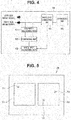
- Fig. 4 is a block diagram illustrating a configuration of function units which detect and correct a white spot in the image processing unit of the endoscope system according to the first embodiment.
- the image processing unit 32 includes a disparity adjusting unit 61 configured to adjust a value of disparity of the left side image signal and the right side image signal which are two image signals having different optical characteristics (in the present embodiment, that is, having disparity), a comparing unit 62 configured to compare luminance values of the left side image signal and the right side image signal adjusted at the disparity adjusting unit 61, a white spot detecting unit 63 configured to detect a white spot on the image pickup device 25 based on information compared at the comparing unit 62, and a white spot correcting unit 64 configured to perform predetermined correction on a pixel where the white spot occurs based on a detection result at the white spot detecting unit 63.
- a disparity adjusting unit 61 configured to adjust a value of disparity of the left side image signal and the right side image signal which are two image signals having different optical characteristics (in the present embodiment, that is, having disparity)
- a comparing unit 62 configured to compare luminance values of the left side image signal and the right side image signal adjusted
- the disparity adjusting unit 61 stores the "disparity information" stored in the ID memory 20 in the endoscope 2 connected to the processor 3 under control of the control unit 31, and performs adjustment so that disparity between the left side image signal relating to the first region 51 and the right side image signal relating to the second region 52 having disparity becomes substantially zero based on this disparity information.
- adjustment is performed so that the disparity becomes substantially zero by displacing a visual direction relating to the left side image signal by an amount corresponding to the disparity so as to match a visual direction relating to the right side image signal.
- the comparing unit 62 compares a luminance value of each pixel in the left side image signal relating to the first region 51 for which the disparity is adjusted to be substantially zero at the disparity adjusting unit 61 and a luminance value of each pixel in the right side image signal relating to the second region 52 for each pixel under control of the control unit 31.
- the white spot detecting unit 63 detects whether or not there is a white spot on the image pickup device 25 based on the comparison result of the luminance value for each pixel in the first region 51 and the second region 52 compared at the comparing unit 62 under control of the control unit 31.
- the white spot detecting unit 63 determines that a white spot occurs at a portion of the pixel 71.
- the white spot detecting unit 63 determines that white spots occur at portions of the pixel 72 and the pixel 73.
- the white spot correcting unit 64 performs predetermined correction on the pixels where the white spots occur, in the above-described case, the pixels 71, 72 and 73, based on the detection result at the white spot detecting unit 63 so as to reduce influence of the white spots.
- correction is performed by replacing an output signal relating to the pixel 71 in the first region 51 where the white spot occurs with an output signal relating to the corresponding pixel 71a in the second region 52. Further, in a similar manner, correction is performed by replacing an output signal relating to the pixel 72 in the second region 52 where the white spot occurs with an output signal relating to the corresponding pixel 72a in the first region 51.
- correction may be performed by performing complementation based on information of surrounding pixels.
- the image processing unit 32 includes a synthesizing unit 65 configured to perform predetermined 3D synthesis processing on the left side image signal and the right side image signal for which the white spots are corrected at the white spot correcting unit 64 and output the synthesized signal, and outputs one video signal subjected to 3D synthesis processing at the synthesizing unit 65 to the monitor 5.
- a synthesizing unit 65 configured to perform predetermined 3D synthesis processing on the left side image signal and the right side image signal for which the white spots are corrected at the white spot correcting unit 64 and output the synthesized signal, and outputs one video signal subjected to 3D synthesis processing at the synthesizing unit 65 to the monitor 5.
- predetermined 3D synthesis processing is performed on the image pickup signals corresponding to the two image pickup regions at the image processing unit 32, and the result is outputted to a normal monitor as one video signal
- the present invention is not limited to this, and, it is also possible to employ a so-called 3D compatible monitor apparatus as the monitor 5, and perform publicly known 3D processing as appropriate on the two video signals having disparity without performing the above-described synthesis processing and display the result.
- image formation position information indicating positions (regions) on the image pickup surface of the image pickup device 25 where the two optical images are formed is acquired in advance through inspection for each endoscope to be shipped, and the "image formation position information" is stored in the ID memory 20 disposed at the connector 12 for signal.
- control unit 31 acquires the "image formation position information" and the "disparity information" stored in the ID memory 20.
- the pre-processing unit 33 receives input of the image pickup signal from the image pickup device 25 and performs predetermined pre-processing under control of the control unit 31, and the image pickup region cut out unit in the image processing unit 32 cuts out predetermined image pickup regions for the first optical image and the second optical image based on the "image formation position information".
- the image processing unit 32 performs predetermined image processing respectively on the two image pickup regions cut out at the image pickup region cut out unit to generate a left side image signal relating to the first region 51 and a right side image signal relating to the second region 52.
- the disparity adjusting unit 61 in the image processing unit 32 stores the "disparity information" stored in the ID memory 20 in the endoscope 2 and performs adjustment so that disparity between the left side image signal relating to the first region 51 and the right side image signal relating to the second region 52 becomes substantially zero based on the disparity information under control of the control unit 31.
- the comparing unit 62 compares a luminance value of each pixel in the left side image signal relating to the first region 51 and a luminance value of each pixel in the right side image signal relating to the second region 52 for which the disparity is adjusted to become substantially zero at the disparity adjusting unit 61, for each pixel under control of the control unit 31.
- the white spot detecting unit 63 detects whether or not there is a white spot on the image pickup device 25 based on the comparison result of the luminance value for each pixel in the first region 51 and the second region 52 compared at the comparing unit 62 under control of the control unit 31.
- the white spot correcting unit 64 performs predetermined correction on the pixel where the white spot occurs to reduce influence of the white spot when the white spot is detected based on the detection result at the white spot detecting unit 63.
- the image processing unit 32 outputs a synthesized video signal obtained at the synthesizing unit 65 by performing predetermined 3D synthesis processing on the left side image signal and the right side image signal for which the white spot is corrected at the white spot correcting unit 64 toward the monitor 5.
- the endoscope system in the image pickup system which generates a new image for display using two types of images having disparity, it is possible to provide an image pickup system which can detect and correct a white spot pixel accurately.
- an endoscope system according to the second embodiment is an endoscope system including an endoscope which forms two optical images generated by separating one incident optical image on one image pickup device.
- the endoscope system forms the separated two optical images on the image pickup surface of one image pickup device, generates two image pickup signals having different luminance with respect to the two optical images, and acquires a high dynamic range image by converting the two image pickup signals into image signals and synthesizing the image signals.
- Fig. 7 is a diagram illustrating a configuration of the endoscope system according to the second embodiment of the present invention
- Fig. 8 is a diagram illustrating a configuration of an optical member disposed at a distal end portion of an insertion portion in the endoscope system according to the second embodiment
- Fig. 9 is a diagram illustrating an example of two types of optical images formed on the image pickup device in the endoscope system according to the second embodiment.
- the endoscope system 101 has a similar basic configuration to that of the first embodiment, but a configuration of a distal end portion 114 of an insertion portion at the endoscope 102 is different from that of the first embodiment.
- an objective lens 121 on which an optical image of an object such as an affected area is incident is disposed at a distal end portion 114.
- an optical prism 123 is disposed. As illustrated in Fig. 8 , this optical prism 123 is an optical image dividing unit configured to divide the one optical image from the objective lens 121 into a first optical image and a second optical image and emits the divided optical images toward the image pickup device 125.
- the image pickup device 125 is disposed at image formation positions of the first optical image and the second optical image which are outputted as two optical paths (a first optical path and a second optical path) from the optical prism 123.
- a mirror 124b and means for reducing light for example, an ND filter 124a is disposed.
- the first optical image reflected at the prism surface is incident on the optical prism 123 again by being reflected by the mirror 124b while luminance is positively reduced by the ND filter 124a, the first optical image is formed at the image pickup device 125.
- the first optical image formed at the image pickup device 125 has relatively low luminance compared to the second optical image.
- the first optical image is formed as an image for which luminance is reduced by light reducing means.
- the image pickup device 125 forms two types of optical images of the first optical image and the second optical image in predetermined regions corresponding to the respective optical images on the same image pickup surface of the CCD.
- the first optical image with low luminance is formed in a region 151
- the second optical image with high luminance is formed in a region 152.
- image formation position information indicating positions (regions) on the image pickup surface of the image pickup device 125 where the two optical images are formed is acquired in advance through inspection for each endoscope to be shipped, and the "image formation position information" is stored in the ID memory 20 disposed at the connector 12 for signal.
- luminance difference information between the first optical image with low luminance and the second optical image with high luminance is stored in the ID memory 20.
- the processor 103 includes a power supply circuit which is configured to generate power supplies of a plurality of power supply voltages required for operation of the image pickup device, or the like, and which is not illustrated, a signal processing circuit (such as an image processing unit 132 and a pre-processing unit 33) configured to perform predetermined signal processing on an image pickup signal outputted from the image pickup device, a CCD drive circuit 34 configured to drive the image pickup device 25 in the endoscope 2, and a control unit 31 configured to control various kinds of circuits including the power supply circuit, the signal processing circuit and the CCD drive circuit 34.
- a power supply circuit which is configured to generate power supplies of a plurality of power supply voltages required for operation of the image pickup device, or the like, and which is not illustrated
- a signal processing circuit such as an image processing unit 132 and a pre-processing unit 33
- a CCD drive circuit 34 configured to drive the image pickup device 25 in the endoscope 2
- a control unit 31 configured to control various kinds of circuits including the power supply circuit, the
- control unit 31 controls the various kinds of circuits within the processor 103 as described above, and acquires the "image formation position information" and the "luminance difference information" which is individual information of the endoscope 102, stored in the ID memory 20 in the connector 12 for signal when the endoscope 102 is connected to the processor 103.
- the image processing unit 132 includes an image processing unit which is configured to perform predetermined image processing on the output signal from the pre-processing unit 33, and which is not illustrated, and an image pickup region cut out unit which is configured to cut out predetermined image pickup regions for the first optical image and the second optical image based on the "image formation position information" stored in the ID memory 20 under control of the control unit 31, and which is not illustrated.
- the image pickup region cut out unit respectively cuts out a region 151 corresponding to the first optical image and a region 152 corresponding to the second optical image on the image pickup surface based on the "image formation position information" of the first optical image and the second optical image formed on the image pickup surface of the image pickup device 25, which is individual information of the endoscope 102 connected to the processor 103.
- the image processing unit 132 performs predetermined image processing respectively in the two image pickup regions (the region 151 and the region 152) cut out at the image pickup region cut out unit to generate two image signals for display (in the present embodiment, a low luminance image signal relating to the region 151 and a high luminance image signal relating to the region 152).
- the image processing unit 132 has a function of detecting a white spot at the image pickup device 125 based on the low luminance image signal relating to the region 151 and the high luminance image signal relating to the region 152 and correcting the white spot.
- the white spot detection and correction function in the second embodiment will be described below.
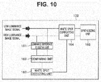
- Fig. 10 is a block diagram illustrating a configuration of function units which detect and correct a white spot at the image processing unit of the endoscope system according to the second embodiment.
- the image processing unit 132 includes a luminance difference adjusting unit 161 configured to adjust a difference of luminance values between the low luminance image signal and the high luminance image signal which are two image signals having different optical characteristics (in the present embodiment, having different luminance values), a comparing unit 162 configured to compare the luminance value between the low luminance image signal and the high luminance image signal adjusted at the luminance difference adjusting unit 161, a white spot detecting unit 163 configured to detect a white spot on the image pickup device 125 based on information compared at the comparing unit 162, and a white spot correcting unit 164 configured to perform predetermined correction on a pixel where the white spot occurs based on the detection result at the white spot detecting unit 163.
- a luminance difference adjusting unit 161 configured to adjust a difference of luminance values between the low luminance image signal and the high luminance image signal which are two image signals having different optical characteristics (in the present embodiment, having different luminance values)
- a comparing unit 162 configured to compare the luminance value between the low
- the luminance difference adjusting unit 161 stores the "luminance difference information" stored in the ID memory 20 in the endoscope 2 connected to the processor 3 under control of the control unit 31, and performs adjustment based on this luminance difference information so that a luminance difference between the low luminance image signal relating to the region 151 and the high luminance image signal relating to the region 152 having different luminance values becomes substantially zero.
- adjustment is performed so that the luminance difference becomes substantially zero by adjusting a gain relating to the low luminance image signal so as to match the luminance value of the high luminance image signal.
- the comparing unit 162 compares for each pixel, a luminance value of each pixel in the low luminance image signal relating to the region 151 and a luminance value of each pixel in the high luminance image signal relating to the region 152, for which the luminance difference is adjusted to be substantially zero at the luminance difference adjusting unit 161, under control of the control unit 31.
- the white spot detecting unit 163 detects whether or not there is a white spot on the image pickup device 125 based on the comparison result of the luminance values for each pixel in the region 151 and the region 152 compared at the comparing unit 162, under control of the control unit 31. Because the method for detecting whether or not there is a white spot is the same as that in the first embodiment, detailed description will be omitted here.
- the white spot correcting unit 164 performs predetermined correction on a pixel where a white spot occurs based on the detection result at the white spot detecting unit 163 to reduce influence of the white spot. Because this white spot correction method is the same as that in the first embodiment, detailed description will be omitted here.
- the image processing unit 132 includes a synthesizing unit 615 configured to perform predetermined 3D synthesis processing on the low luminance image signal and the high luminance image signal for which a white spot is corrected at the white spot correcting unit 164 and output the result, and output one video signal subjected to 3D synthesis processing at this synthesizing unit 165 toward the monitor 5.
- a synthesizing unit 615 configured to perform predetermined 3D synthesis processing on the low luminance image signal and the high luminance image signal for which a white spot is corrected at the white spot correcting unit 164 and output the result, and output one video signal subjected to 3D synthesis processing at this synthesizing unit 165 toward the monitor 5.
- image formation position information indicating positions (regions) on the image pickup surface of the image pickup device 125 where the two optical images are formed is acquired in advance through inspection for each endoscope to be shipped, and the "image formation position information" is stored in the ID memory 20 disposed at the connector 12 for signal.
- luminance difference information between the first optical image with low luminance and the second optical image with high luminance at the endoscope 102 is stored in the ID memory 20.
- the control unit 31 acquires the "image formation position information" and the "luminance difference information" stored in the ID memory 20.
- the pre-processing unit 33 receives input of the image pickup signal from the image pickup device 125 and performs predetermined pre-processing, and the image pickup region cut out unit of the image processing unit 132 cuts out predetermined image pickup regions for the first optical image and the second optical image based on the "image formation position information", under control of the control unit 31.
- the image processing unit 132 preforms predetermined image processing respectively in the two image pickup regions cut out at the image pickup region cut out unit to generate a low luminance image signal relating to the region 151 and a high luminance image signal relating to the region 152.
- the luminance difference adjusting unit 161 in the image processing unit 132 stores the "luminance difference information" stored in the ID memory 20 in the endoscope 102 and performs adjustment so that a luminance difference between the low luminance image signal relating to the region 151 and the high luminance image signal relating to the region 152 becomes substantially zero based on this luminance difference information, under control of the control unit 31.
- the comparing unit 162 compares for each pixel a luminance value of each pixel in the low luminance image signal relating to the region 151 and a luminance value of each pixel in the high luminance image signal relating to the region 152 for which the luminance difference is adjusted to be substantially zero at the luminance difference adjusting unit 161, under control of the control unit 31.
- the white spot detecting unit 163 detects whether or not there is a white spot on the image pickup device 125 based on the comparison result of the luminance values for each pixel in the region 151 and the region 152 compared at the comparing unit 162, under control of the control unit 31.
- the white spot correcting unit 164 performs predetermined correction on the pixel where the white spot occurs based on the detection result at the white spot detecting unit 163 to reduce influence of the white spot.
- the image processing unit 132 performs predetermined 3D synthesis processing on the low luminance image signal and the high luminance image signal for which the white spot is corrected by the white spot correcting unit 164 at the synthesizing unit 165 and outputs the synthesized video signal toward the monitor 5.
- an image pickup system which generates a new image for display using two types of images having different luminance values, it is possible to provide an image pickup system which can detect and correct a white spot pixel accurately.
- the present invention can be applied not only to an endoscope system having an endoscope on which a solid-state image pickup device as in the first embodiment and the second embodiment is mounted, but can be applied to an image pickup system including a solid-state image pickup device, which can generate a new image for display using two types of images and detect a white spot pixel.
Landscapes
- Health & Medical Sciences (AREA)
- Life Sciences & Earth Sciences (AREA)
- Physics & Mathematics (AREA)
- Engineering & Computer Science (AREA)
- Surgery (AREA)
- Optics & Photonics (AREA)
- Multimedia (AREA)
- Signal Processing (AREA)
- Radiology & Medical Imaging (AREA)
- General Health & Medical Sciences (AREA)
- Biomedical Technology (AREA)
- Biophysics (AREA)
- Nuclear Medicine, Radiotherapy & Molecular Imaging (AREA)
- Heart & Thoracic Surgery (AREA)
- Medical Informatics (AREA)
- Molecular Biology (AREA)
- Animal Behavior & Ethology (AREA)
- Pathology (AREA)
- Public Health (AREA)
- Veterinary Medicine (AREA)
- Astronomy & Astrophysics (AREA)
- General Physics & Mathematics (AREA)
- Endoscopes (AREA)
- Instruments For Viewing The Inside Of Hollow Bodies (AREA)
- Transforming Light Signals Into Electric Signals (AREA)
Applications Claiming Priority (2)
| Application Number | Priority Date | Filing Date | Title |
|---|---|---|---|
| JP2014210281 | 2014-10-14 | ||
| PCT/JP2015/078091 WO2016059983A1 (ja) | 2014-10-14 | 2015-10-02 | 撮像システム |
Publications (2)
| Publication Number | Publication Date |
|---|---|
| EP3145176A1 true EP3145176A1 (de) | 2017-03-22 |
| EP3145176A4 EP3145176A4 (de) | 2018-04-18 |
Family
ID=55746531
Family Applications (1)
| Application Number | Title | Priority Date | Filing Date |
|---|---|---|---|
| EP15851024.8A Withdrawn EP3145176A4 (de) | 2014-10-14 | 2015-10-02 | Bildaufnahmesystem |
Country Status (5)
| Country | Link |
|---|---|
| US (1) | US10206554B2 (de) |
| EP (1) | EP3145176A4 (de) |
| JP (1) | JP6017735B2 (de) |
| CN (1) | CN106664381A (de) |
| WO (1) | WO2016059983A1 (de) |
Cited By (3)
| Publication number | Priority date | Publication date | Assignee | Title |
|---|---|---|---|---|
| WO2018234545A1 (en) * | 2017-06-22 | 2018-12-27 | Helmholtz Zentrum München Deutsches Forschungszentrum Für Gesundheit Und Umwelt (Gmbh) | System for endoscopic imaging and method for processing images |
| US11089294B2 (en) | 2017-12-22 | 2021-08-10 | Olympus Corporation | Endoscope inspection system, endoscope inspection apparatus, endoscope package, and endoscope inspection method |
| US12185916B2 (en) | 2020-03-06 | 2025-01-07 | Olympus Corporation | Endoscope apparatus, processor for endoscope image, and method for generating endoscope image |
Families Citing this family (5)
| Publication number | Priority date | Publication date | Assignee | Title |
|---|---|---|---|---|
| EP3281576A1 (de) * | 2015-05-14 | 2018-02-14 | Olympus Corporation | Stereoskopische endoskopvorrichtung |
| JP6602979B2 (ja) * | 2016-07-11 | 2019-11-06 | オリンパス株式会社 | 内視鏡装置 |
| WO2018154661A1 (ja) * | 2017-02-22 | 2018-08-30 | オリンパス株式会社 | 内視鏡のための画像処理装置及び内視鏡システム |
| JP6463573B1 (ja) * | 2017-06-07 | 2019-02-06 | オリンパス株式会社 | 内視鏡撮像システム |
| WO2020084784A1 (ja) * | 2018-10-26 | 2020-04-30 | オリンパス株式会社 | 画像処理装置および内視鏡システム |
Family Cites Families (25)
| Publication number | Priority date | Publication date | Assignee | Title |
|---|---|---|---|---|
| JP3785520B2 (ja) | 1997-03-19 | 2006-06-14 | コニカミノルタホールディングス株式会社 | 電子カメラ |
| US6529640B1 (en) * | 1998-06-09 | 2003-03-04 | Nikon Corporation | Image processing apparatus |
| JPH11355650A (ja) * | 1998-06-09 | 1999-12-24 | Nikon Corp | 画像取り込み装置 |
| JP3587506B2 (ja) * | 1999-08-30 | 2004-11-10 | 富士重工業株式会社 | ステレオカメラの調整装置 |
| JP2001086411A (ja) | 1999-09-13 | 2001-03-30 | Matsushita Electric Ind Co Ltd | 固体撮像装置 |
| JP2001148865A (ja) | 1999-11-19 | 2001-05-29 | Minolta Co Ltd | 画像入力装置 |
| JP2003032559A (ja) | 2001-07-17 | 2003-01-31 | Victor Co Of Japan Ltd | 撮像装置 |
| JP2004313523A (ja) * | 2003-04-17 | 2004-11-11 | Pentax Corp | 固体撮像素子、電子内視鏡 |
| JP2005311983A (ja) * | 2004-04-26 | 2005-11-04 | Olympus Corp | 画像処理装置 |
| JP2006086839A (ja) * | 2004-09-16 | 2006-03-30 | Canon Inc | 欠陥画素補正装置 |
| JP2008164367A (ja) * | 2006-12-27 | 2008-07-17 | Matsushita Electric Ind Co Ltd | 固体撮像装置、カメラ、車両及び監視装置 |
| JP5246851B2 (ja) | 2008-03-24 | 2013-07-24 | 株式会社日立国際電気 | 画素欠陥補正方法及びテレビジョンカメラ |
| US8908058B2 (en) * | 2009-04-18 | 2014-12-09 | Lytro, Inc. | Storage and transmission of pictures including multiple frames |
| JPWO2012017735A1 (ja) * | 2010-08-02 | 2013-10-03 | オリンパスメディカルシステムズ株式会社 | 内視鏡システム |
| JP2012065204A (ja) | 2010-09-16 | 2012-03-29 | Toshiba Corp | 複眼撮像装置、信号処理装置、複眼撮像装置の制御方法 |
| JP2012134875A (ja) * | 2010-12-22 | 2012-07-12 | Olympus Corp | 内視鏡装置 |
| KR101554241B1 (ko) * | 2011-06-24 | 2015-09-18 | 소프트키네틱 소프트웨어 | 3차원 이미지에서의 결함성 픽셀 깊이 데이터 값의 깊이 맵 품질 향상을 위한 방법 |
| JP5824953B2 (ja) * | 2011-08-09 | 2015-12-02 | 株式会社ソシオネクスト | 画像処理装置、画像処理方法及び撮像装置 |
| US9560334B2 (en) * | 2011-09-08 | 2017-01-31 | Qualcomm Incorporated | Methods and apparatus for improved cropping of a stereoscopic image pair |
| JP5904886B2 (ja) * | 2012-06-25 | 2016-04-20 | シャープ株式会社 | 撮像装置、欠陥処理方法、欠陥処理プログラムおよび電子情報機器 |
| EP2873028A4 (de) * | 2012-06-28 | 2016-05-25 | Pelican Imaging Corp | Systeme und verfahren zur erkennung defekter kamera-arrays, optischer arrays und sensoren |
| EP2750391B1 (de) * | 2012-12-31 | 2017-03-22 | Nokia Technologies Oy | Verfahren, Vorrichtung und Computerprogrammprodukt zur Verarbeitung von Bildern |
| US9124831B2 (en) * | 2013-03-13 | 2015-09-01 | Pelican Imaging Corporation | System and methods for calibration of an array camera |
| WO2016100776A1 (en) * | 2014-12-19 | 2016-06-23 | Boston Scientific Scimed, Inc | Calibrated medical imaging devices and related methods |
| KR102346961B1 (ko) * | 2015-03-18 | 2022-01-04 | 삼성전자주식회사 | 이미지 처리 장치 및 이를 포함하는 노이즈 제거 시스템 |
-
2015
- 2015-10-02 CN CN201580033789.3A patent/CN106664381A/zh active Pending
- 2015-10-02 WO PCT/JP2015/078091 patent/WO2016059983A1/ja not_active Ceased
- 2015-10-02 EP EP15851024.8A patent/EP3145176A4/de not_active Withdrawn
- 2015-10-02 JP JP2016522076A patent/JP6017735B2/ja active Active
-
2016
- 2016-12-14 US US15/378,145 patent/US10206554B2/en active Active
Cited By (3)
| Publication number | Priority date | Publication date | Assignee | Title |
|---|---|---|---|---|
| WO2018234545A1 (en) * | 2017-06-22 | 2018-12-27 | Helmholtz Zentrum München Deutsches Forschungszentrum Für Gesundheit Und Umwelt (Gmbh) | System for endoscopic imaging and method for processing images |
| US11089294B2 (en) | 2017-12-22 | 2021-08-10 | Olympus Corporation | Endoscope inspection system, endoscope inspection apparatus, endoscope package, and endoscope inspection method |
| US12185916B2 (en) | 2020-03-06 | 2025-01-07 | Olympus Corporation | Endoscope apparatus, processor for endoscope image, and method for generating endoscope image |
Also Published As
| Publication number | Publication date |
|---|---|
| JP6017735B2 (ja) | 2016-11-02 |
| WO2016059983A1 (ja) | 2016-04-21 |
| JPWO2016059983A1 (ja) | 2017-04-27 |
| US20170086649A1 (en) | 2017-03-30 |
| EP3145176A4 (de) | 2018-04-18 |
| US10206554B2 (en) | 2019-02-19 |
| CN106664381A (zh) | 2017-05-10 |
Similar Documents
| Publication | Publication Date | Title |
|---|---|---|
| US10206554B2 (en) | Image pickup system with white spot correction | |
| US10523911B2 (en) | Image pickup system | |
| US9763558B2 (en) | Endoscope apparatus, method for operating endoscope apparatus, and information storage device | |
| US9538108B2 (en) | Endoscope system and pixel correction method | |
| US8882658B2 (en) | Endoscope system | |
| US8860794B2 (en) | Endoscope system | |
| US10667676B2 (en) | Electronic endoscope and endoscope system that sets a gain parameter according to a gamma characteristic of a connected processor | |
| WO2018043428A1 (ja) | 内視鏡および内視鏡システム | |
| US20120092471A1 (en) | Endoscopic device | |
| JP2008043742A (ja) | 電子内視鏡システム | |
| US9113806B2 (en) | Endoscope apparatus for measuring a spatial characteristic | |
| US12502053B2 (en) | Imaging system, endoscope, and control device | |
| US10559072B2 (en) | Image detection device and image detection system | |
| US9826169B2 (en) | Image pickup apparatus, image processing apparatus, and method for activating image pickup apparatus | |
| US10326944B2 (en) | Image pickup system and signal processing apparatus | |
| JP2013179580A (ja) | 撮像装置 | |
| JP2012134875A (ja) | 内視鏡装置 | |
| WO2021235468A1 (ja) | 内視鏡システムおよび制御方法 | |
| JPH06335449A (ja) | 電子内視鏡装置 | |
| US20240155249A1 (en) | Image processing apparatus, control method thereof, and non-transitory computer-readable storage medium | |
| JP2003070735A (ja) | 電子内視鏡装置 | |
| WO2016035366A1 (ja) | 撮像システム | |
| WO2020084784A1 (ja) | 画像処理装置および内視鏡システム | |
| CN120360464A (zh) | 一种内窥镜成像方法、装置及电子设备和存储介质 | |
| WO2015076293A1 (ja) | 内視鏡用画像生成装置及び内視鏡用画像生成方法 |
Legal Events
| Date | Code | Title | Description |
|---|---|---|---|
| STAA | Information on the status of an ep patent application or granted ep patent |
Free format text: STATUS: THE INTERNATIONAL PUBLICATION HAS BEEN MADE |
|
| PUAI | Public reference made under article 153(3) epc to a published international application that has entered the european phase |
Free format text: ORIGINAL CODE: 0009012 |
|
| STAA | Information on the status of an ep patent application or granted ep patent |
Free format text: STATUS: REQUEST FOR EXAMINATION WAS MADE |
|
| 17P | Request for examination filed |
Effective date: 20161213 |
|
| AK | Designated contracting states |
Kind code of ref document: A1 Designated state(s): AL AT BE BG CH CY CZ DE DK EE ES FI FR GB GR HR HU IE IS IT LI LT LU LV MC MK MT NL NO PL PT RO RS SE SI SK SM TR |
|
| AX | Request for extension of the european patent |
Extension state: BA ME |
|
| RIC1 | Information provided on ipc code assigned before grant |
Ipc: H04N 5/367 20110101AFI20171205BHEP Ipc: H04N 5/225 20060101ALI20171205BHEP Ipc: H04N 13/02 00000000ALI20171205BHEP |
|
| DAV | Request for validation of the european patent (deleted) | ||
| DAX | Request for extension of the european patent (deleted) | ||
| A4 | Supplementary search report drawn up and despatched |
Effective date: 20180319 |
|
| RIC1 | Information provided on ipc code assigned before grant |
Ipc: H04N 13/20 20180101ALI20180319BHEP Ipc: H04N 5/367 20110101AFI20180319BHEP Ipc: H04N 5/225 20060101ALI20180319BHEP |
|
| RIC1 | Information provided on ipc code assigned before grant |
Ipc: H04N 5/225 20060101ALI20180319BHEP Ipc: H04N 5/367 20110101AFI20180319BHEP Ipc: H04N 13/20 20180101ALI20180319BHEP |
|
| STAA | Information on the status of an ep patent application or granted ep patent |
Free format text: STATUS: THE APPLICATION IS DEEMED TO BE WITHDRAWN |
|
| 18D | Application deemed to be withdrawn |
Effective date: 20181020 |