EP3145212B1 - Procédé de commande d'un appareil d'information et programme - Google Patents
Procédé de commande d'un appareil d'information et programme Download PDFInfo
- Publication number
- EP3145212B1 EP3145212B1 EP16197451.4A EP16197451A EP3145212B1 EP 3145212 B1 EP3145212 B1 EP 3145212B1 EP 16197451 A EP16197451 A EP 16197451A EP 3145212 B1 EP3145212 B1 EP 3145212B1
- Authority
- EP
- European Patent Office
- Prior art keywords
- shutter
- image
- electric
- control section
- display
- Prior art date
- Legal status (The legal status is an assumption and is not a legal conclusion. Google has not performed a legal analysis and makes no representation as to the accuracy of the status listed.)
- Not-in-force
Links
Images


Classifications
-
- G—PHYSICS
- G06—COMPUTING OR CALCULATING; COUNTING
- G06F—ELECTRIC DIGITAL DATA PROCESSING
- G06F3/00—Input arrangements for transferring data to be processed into a form capable of being handled by the computer; Output arrangements for transferring data from processing unit to output unit, e.g. interface arrangements
- G06F3/01—Input arrangements or combined input and output arrangements for interaction between user and computer
- G06F3/048—Interaction techniques based on graphical user interfaces [GUI]
- G06F3/0484—Interaction techniques based on graphical user interfaces [GUI] for the control of specific functions or operations, e.g. selecting or manipulating an object, an image or a displayed text element, setting a parameter value or selecting a range
- G06F3/04847—Interaction techniques to control parameter settings, e.g. interaction with sliders or dials
-
- A—HUMAN NECESSITIES
- A47—FURNITURE; DOMESTIC ARTICLES OR APPLIANCES; COFFEE MILLS; SPICE MILLS; SUCTION CLEANERS IN GENERAL
- A47H—FURNISHINGS FOR WINDOWS OR DOORS
- A47H5/00—Devices for drawing draperies, curtains, or the like
- A47H5/02—Devices for opening and closing curtains
-
- E—FIXED CONSTRUCTIONS
- E06—DOORS, WINDOWS, SHUTTERS, OR ROLLER BLINDS IN GENERAL; LADDERS
- E06B—FIXED OR MOVABLE CLOSURES FOR OPENINGS IN BUILDINGS, VEHICLES, FENCES OR LIKE ENCLOSURES IN GENERAL, e.g. DOORS, WINDOWS, BLINDS, GATES
- E06B3/00—Window sashes, door leaves, or like elements for closing wall or like openings; Layout of fixed or moving closures, e.g. windows in wall or like openings; Features of rigidly-mounted outer frames relating to the mounting of wing frames
- E06B3/32—Arrangements of wings characterised by the manner of movement; Arrangements of movable wings in openings; Features of wings or frames relating solely to the manner of movement of the wing
- E06B3/48—Wings connected at their edges, e.g. foldable wings
- E06B3/485—Sectional doors
-
- E—FIXED CONSTRUCTIONS
- E06—DOORS, WINDOWS, SHUTTERS, OR ROLLER BLINDS IN GENERAL; LADDERS
- E06B—FIXED OR MOVABLE CLOSURES FOR OPENINGS IN BUILDINGS, VEHICLES, FENCES OR LIKE ENCLOSURES IN GENERAL, e.g. DOORS, WINDOWS, BLINDS, GATES
- E06B9/00—Screening or protective devices for wall or similar openings, with or without operating or securing mechanisms; Closures of similar construction
- E06B9/24—Screens or other constructions affording protection against light, especially against sunshine; Similar screens for privacy or appearance; Slat blinds
- E06B9/26—Lamellar or like blinds, e.g. venetian blinds
- E06B9/28—Lamellar or like blinds, e.g. venetian blinds with horizontal lamellae, e.g. non-liftable
- E06B9/30—Lamellar or like blinds, e.g. venetian blinds with horizontal lamellae, e.g. non-liftable liftable
- E06B9/32—Operating, guiding, or securing devices therefor
-
- G—PHYSICS
- G06—COMPUTING OR CALCULATING; COUNTING
- G06F—ELECTRIC DIGITAL DATA PROCESSING
- G06F3/00—Input arrangements for transferring data to be processed into a form capable of being handled by the computer; Output arrangements for transferring data from processing unit to output unit, e.g. interface arrangements
- G06F3/01—Input arrangements or combined input and output arrangements for interaction between user and computer
- G06F3/048—Interaction techniques based on graphical user interfaces [GUI]
- G06F3/0481—Interaction techniques based on graphical user interfaces [GUI] based on specific properties of the displayed interaction object or a metaphor-based environment, e.g. interaction with desktop elements like windows or icons, or assisted by a cursor's changing behaviour or appearance
- G06F3/04817—Interaction techniques based on graphical user interfaces [GUI] based on specific properties of the displayed interaction object or a metaphor-based environment, e.g. interaction with desktop elements like windows or icons, or assisted by a cursor's changing behaviour or appearance using icons
-
- G—PHYSICS
- G06—COMPUTING OR CALCULATING; COUNTING
- G06F—ELECTRIC DIGITAL DATA PROCESSING
- G06F3/00—Input arrangements for transferring data to be processed into a form capable of being handled by the computer; Output arrangements for transferring data from processing unit to output unit, e.g. interface arrangements
- G06F3/01—Input arrangements or combined input and output arrangements for interaction between user and computer
- G06F3/048—Interaction techniques based on graphical user interfaces [GUI]
- G06F3/0481—Interaction techniques based on graphical user interfaces [GUI] based on specific properties of the displayed interaction object or a metaphor-based environment, e.g. interaction with desktop elements like windows or icons, or assisted by a cursor's changing behaviour or appearance
- G06F3/0482—Interaction with lists of selectable items, e.g. menus
-
- G—PHYSICS
- G06—COMPUTING OR CALCULATING; COUNTING
- G06F—ELECTRIC DIGITAL DATA PROCESSING
- G06F3/00—Input arrangements for transferring data to be processed into a form capable of being handled by the computer; Output arrangements for transferring data from processing unit to output unit, e.g. interface arrangements
- G06F3/01—Input arrangements or combined input and output arrangements for interaction between user and computer
- G06F3/048—Interaction techniques based on graphical user interfaces [GUI]
- G06F3/0484—Interaction techniques based on graphical user interfaces [GUI] for the control of specific functions or operations, e.g. selecting or manipulating an object, an image or a displayed text element, setting a parameter value or selecting a range
- G06F3/04842—Selection of displayed objects or displayed text elements
-
- G—PHYSICS
- G06—COMPUTING OR CALCULATING; COUNTING
- G06F—ELECTRIC DIGITAL DATA PROCESSING
- G06F3/00—Input arrangements for transferring data to be processed into a form capable of being handled by the computer; Output arrangements for transferring data from processing unit to output unit, e.g. interface arrangements
- G06F3/01—Input arrangements or combined input and output arrangements for interaction between user and computer
- G06F3/048—Interaction techniques based on graphical user interfaces [GUI]
- G06F3/0487—Interaction techniques based on graphical user interfaces [GUI] using specific features provided by the input device, e.g. functions controlled by the rotation of a mouse with dual sensing arrangements, or of the nature of the input device, e.g. tap gestures based on pressure sensed by a digitiser
- G06F3/0488—Interaction techniques based on graphical user interfaces [GUI] using specific features provided by the input device, e.g. functions controlled by the rotation of a mouse with dual sensing arrangements, or of the nature of the input device, e.g. tap gestures based on pressure sensed by a digitiser using a touch-screen or digitiser, e.g. input of commands through traced gestures
- G06F3/04883—Interaction techniques based on graphical user interfaces [GUI] using specific features provided by the input device, e.g. functions controlled by the rotation of a mouse with dual sensing arrangements, or of the nature of the input device, e.g. tap gestures based on pressure sensed by a digitiser using a touch-screen or digitiser, e.g. input of commands through traced gestures for inputting data by handwriting, e.g. gesture or text
-
- G—PHYSICS
- G08—SIGNALLING
- G08C—TRANSMISSION SYSTEMS FOR MEASURED VALUES, CONTROL OR SIMILAR SIGNALS
- G08C17/00—Arrangements for transmitting signals characterised by the use of a wireless electrical link
-
- H—ELECTRICITY
- H04—ELECTRIC COMMUNICATION TECHNIQUE
- H04L—TRANSMISSION OF DIGITAL INFORMATION, e.g. TELEGRAPHIC COMMUNICATION
- H04L12/00—Data switching networks
- H04L12/28—Data switching networks characterised by path configuration, e.g. LAN [Local Area Networks] or WAN [Wide Area Networks]
- H04L12/2803—Home automation networks
- H04L12/2816—Controlling appliance services of a home automation network by calling their functionalities
- H04L12/282—Controlling appliance services of a home automation network by calling their functionalities based on user interaction within the home
-
- H—ELECTRICITY
- H04—ELECTRIC COMMUNICATION TECHNIQUE
- H04L—TRANSMISSION OF DIGITAL INFORMATION, e.g. TELEGRAPHIC COMMUNICATION
- H04L67/00—Network arrangements or protocols for supporting network services or applications
- H04L67/01—Protocols
- H04L67/02—Protocols based on web technology, e.g. hypertext transfer protocol [HTTP]
- H04L67/025—Protocols based on web technology, e.g. hypertext transfer protocol [HTTP] for remote control or remote monitoring of applications
-
- A—HUMAN NECESSITIES
- A47—FURNITURE; DOMESTIC ARTICLES OR APPLIANCES; COFFEE MILLS; SPICE MILLS; SUCTION CLEANERS IN GENERAL
- A47H—FURNISHINGS FOR WINDOWS OR DOORS
- A47H5/00—Devices for drawing draperies, curtains, or the like
- A47H5/02—Devices for opening and closing curtains
- A47H2005/025—Devices for opening and closing curtains controlled by electronic sensors
-
- G—PHYSICS
- G06—COMPUTING OR CALCULATING; COUNTING
- G06F—ELECTRIC DIGITAL DATA PROCESSING
- G06F2203/00—Indexing scheme relating to G06F3/00 - G06F3/048
- G06F2203/048—Indexing scheme relating to G06F3/048
- G06F2203/04808—Several contacts: gestures triggering a specific function, e.g. scrolling, zooming, right-click, when the user establishes several contacts with the surface simultaneously; e.g. using several fingers or a combination of fingers and pen
-
- G—PHYSICS
- G08—SIGNALLING
- G08C—TRANSMISSION SYSTEMS FOR MEASURED VALUES, CONTROL OR SIMILAR SIGNALS
- G08C2201/00—Transmission systems of control signals via wireless link
- G08C2201/30—User interface
-
- G—PHYSICS
- G08—SIGNALLING
- G08C—TRANSMISSION SYSTEMS FOR MEASURED VALUES, CONTROL OR SIMILAR SIGNALS
- G08C2201/00—Transmission systems of control signals via wireless link
- G08C2201/40—Remote control systems using repeaters, converters, gateways
-
- G—PHYSICS
- G08—SIGNALLING
- G08C—TRANSMISSION SYSTEMS FOR MEASURED VALUES, CONTROL OR SIMILAR SIGNALS
- G08C2201/00—Transmission systems of control signals via wireless link
- G08C2201/50—Receiving or transmitting feedback, e.g. replies, status updates, acknowledgements, from the controlled devices
Definitions
- the present disclosure relates to a method for controlling an information apparatus and a program.
- Patent Document 1 discloses a technology for operating an open/close element of an architectural electric open/close device using a remote operation device.
- a remote operation unit 7 has operation switches PBU, PBD, and PBS for opening, closing, and stopping.
- the remote operation unit 7 outputs an operation signal in which a device code that specifies a shutter device 1 as a control target and a data code that specifies operation (opening, closing, and stopping) of a shutter curtain are formed by one word (paragraphs [0009] and [0024]).
- an input operation signal is an open/close operation signal
- a receiving section 9 of an operation unit 8 enables open/close operation of a shutter curtain 2 when a predetermined number of words of the operation signal are input continuously.
- the receiving section 9 stops open/close operation of the shutter curtain 2 when one word of the operation signal is input (paragraph [0025]).
- Patent Documents 1 described above needs a further improvement.
- Patent Document 1 Japanese Patent Application Laid-open No. 2011-94408 (for example, paragraphs [0009], [0024], [0025] and the like)
- US-2010/145485 A1 describes a method of operating a home automation system which comprises: at least one home automation equipment item of a building, the home automation equipment item being associated with a specific equipment control means, a device for controlling this home automation equipment item, comprising a display and control screen on which a portion of the screen is assigned to the display of a first graphic representation, associated with this equipment item, the control device being separate from the specific control means, which system comprises a step for setting at least one value of a parameter of the home automation equipment item involved in the definition of a scenario, this setting step being able to be both implemented by action on the specific control means so as to cause a phase for modification of the state of the home automation equipment item and by action on the control device so as to cause a phase for modification of the appearance of the first graphic representation of the home automation equipment item.
- EP 2 293 531 A1 relates to an electronic device and control method thereof.
- a mobile terminal is presented.
- the mobile terminal includes a display module, a short-range communication module configured to perform short-range communication, and a controller configured to search for at least one device available for short-range communication via the short-range communication module, acquire location information of the at least one searched other electronic device, and display the at least one searched electronic device reflecting the acquired location information on the display module.
- CN 102 289 319 A relates to a control device with a touch screen and a control method of a control device.
- the control device comprises a control end and a control module connected to the control end, wherein the control end is provided with a touch screen, and the touch screen includes a display module for displaying operation control information, the operation control information corresponding to a stroke of the motor controlled by the control module.
- the invention is defined by the subject-matter of the independent claims.
- the dependent claims are directed to advantageous embodiments.
- a method for controlling an information apparatus the information apparatus having a touch panel display and being connected to a network, an electric shutter device being controlled over the network, the electric shutter device being capable of opening and closing a shutter through a remote operation, the method causing a computer of the information apparatus to:
- the remote operation unit 7 has the operation switches PBU, PBD, and PBS for opening, closing, and stopping. That is, the shutter of the electric shutter device is opened and closed by a user by pressing the operation switches of the remote operation unit 7. Therefore, in Patent Document 1, the shutter of the electric shutter device is opened and closed through simple control in which an open operation signal, a close operation signal, or a stop operation signal is transmitted by depressing the open operation button, the close operation button, or the stop button.
- the remote operation unit 7 does not have a display section that displays the opening/closing condtion of the shutter of the electric shutter device. Therefore, the operating condition of the shutter of the electric shutter device cannot be confirmed at the same time while operating to open, close, or stop the shutter of the electric shutter device.
- the shutter of the electric shutter device may be opened halfway to take sunlight into a room while blocking the sun rays with the shutter half open.
- the technology disclosed in Patent Document 1 described above it is necessary to take the trouble to go near the electric shutter device for visual confirmation, and the shutter position cannot be appropriately controlled remotely.
- the electric shutter device is different from devices of a type that is turned on and off to establish a desired state in that the electric shutter device involves open/close operation. For example, there is a case where the shutter of the electric shutter device is opened halfway and further opened or closed for adjustment while confirming the position of the opened shutter. In this case, taking the trouble to go near the electric shutter device for visual confirmation reduces the effect of a remote operation.
- the size of the remote operation unit 7 is limited from the viewpoint of operability, and not necessarily satisfactory simply because the remote operation unit 7 can be provided with a display section.
- the remote operation unit 7 is unsuitable for a process of finely adjusting opening and closing of the shutter of the electric shutter device unless the display section has a more or less large display area.
- An aspect of the present disclosure is a method for controlling an information apparatus, the information apparatus having a touch panel display and being connected to a network, an electric shutter device being controlled over the network, the electric shutter device being capable of opening and closing a shutter through a remote operation, the method causing a computer of the information apparatus to:
- a shutter image representing the shutter of the electric shutter device appears on the operation screen. Then, when a swipe operation is sensed on the shutter image, for example, on the operation screen, control is performed so as to move the shutter of the electric shutter device in a swipe direction of the swipe operation.
- Movement of the shutter of the electric shutter device is controlled through the swipe operation, for example. Therefore, the shutter of the electric shutter device may be not only opened completely but also opened halfway. For example, when sun rays are strong such as during summer, the shutter of the electric shutter device may be opened to an intermediate position to take sunlight into a room while blocking the sun rays with the shutter opened halfway. Also in this case, the shutter of the electric shutter device can be opened to an intermediate position.
- the shutter of the electric shutter device is opened halfway and further opened or closed while confirming the opened state.
- the open-close state of the shutter of the electric shutter device can be confirmed on the operation screen while performing an operation of moving the shutter of the electric shutter device.
- the operation screen also serves as a confirmation screen for confirmation as to what position the shutter is opened to in accordance with an instruction given by the user by performing an operation of the operation screen.
- the operation instruction screen and the moving state confirmation screen are common to each other. Therefore, it is possible to effectively process an operation of moving the shutter of the electric shutter device and to make the most of the display area of the operation screen.
- the operation screen also serves as display for confirmation of the open/close state of the shutter.
- the operation screen can be used not only to stop the shutter of the electric shutter device in the middle of being opened and closed, but also to confirm that an instruction to stop the shutter at a desired position has been given at the same time.
- opening and closing of the shutter of the electric shutter device can be stopped without the shutter moving past the desired position.
- the open/close position of the shutter of the electric shutter device can be finely adjusted.
- a distance control command may be output to the network as the movement control command when the swipe operation is sensed on the operation screen, the distance control command causing the shutter of the electric shutter device to move in the swipe direction a distance in accordance with an amount of movement in the swipe direction of the swipe operation.
- the shutter of the electric shutter device may be not only opened completely but also opened halfway.
- movement of the shutter of the electric shutter device may comprise movement to open the shutter of the electric shutter device or movement to close the shutter of the electric shutter device.
- the electric shutter device may have the shutter which opens or closes in one direction.
- the shutter represented in the shutter image may be moved a distance in accordance with an amount of movement in the swipe direction of the swipe operation.
- the shutter image may comprise an image representing the shutter of the electric shutter device used as a storm sash provided at a window, and in a case where the shutter represented in the shutter image is moved in an opening direction, a window image representing the window which has been hidden behind the shutter of the electric shutter device may be displayed in a region corresponding to the shutter image.
- the shutter of the electric shutter device in the case where the shutter of the electric shutter device is used for a plurality of purposes, it may not be discriminated what purpose the shutter of the electric shutter device as the operation target is used for, and a shutter of an electric shutter device that is different from the shutter of the intended electric shutter device may be erroneously operated.
- the shutter of the electric shutter device used as a storm sash provided at a window for example, may be erroneously opened when it is intended to open the shutter of the electric shutter device used as a gate provided in a garage.
- a window image representing the window which has been hidden behind the shutter of the electric shutter device is displayed. Therefore, an erroneous operation can be known through the same screen as the operation screen in the case where the moving state of the shutter of the electric shutter device is confirmed through the operation screen. As a result, it is possible to easily prevent an erroneous operation even in the case where the moving state of the shutter of the electric shutter device is confirmed through the operation screen rather than being confirmed with the shutter of the electric shutter device as a real object.
- the window image may be hidden behind the shutter represented in the shutter image.
- the shutter image may comprise an image representing the shutter of the electric shutter device used as a gate provided in a garage, and in a case where the shutter represented in the shutter image is moved in an opening direction, a vehicle image representing a vehicle in the garage which has been hidden behind the shutter of the electric shutter device may be displayed in a region corresponding to the shutter image.
- the shutter of the electric shutter device in a case where the shutter of the electric shutter device is used for a plurality of purposes, it may not be discriminated what purpose the shutter of the electric shutter device as the operation target is used for, and the shutter of an electric shutter device that is different from the shutter of the intended electric shutter device may be erroneously operated.
- the shutter of the electric shutter device used as a gate provided in a garage for example, may be erroneously opened when it is intended to operate to open the shutter of the electric shutter device used as a storm sash provided at a window.
- a vehicle image representing a vehicle in the garage which has been hidden behind the shutter of the electric shutter device is displayed. Therefore, an erroneous operation can be known through the same screen as the operation screen in the case where the moving state of the shutter of the electric shutter device is confirmed through the operation screen. As a result, it is possible to easily prevent an erroneous operation even in the case where the moving state of the shutter of the electric shutter device is confirmed through the operation screen rather than being confirmed with the shutter of the electric shutter device as a real object.
- the vehicle image may be hidden behind the shutter in the shutter image.
- positional information indicating a position of the shutter of the electric shutter device may be received via the network, and state information representing a position of an end portion of the shutter of the electric shutter device may be displayed in a region corresponding to the shutter image in accordance with the received positional information.
- state information representing the position of the end portion of the shutter of the electric shutter device is displayed in a region corresponding to the shutter image representing the shutter of the electric shutter device besides an image representing to what location the shutter of the electric shutter device is moved by an operation of the operation screen.
- a gap is present between the shutter image representing the shutter of the electric shutter device in the operation screen and the actual position to which the shutter of the electric shutter device has been moved. Also in such a case, the user is allowed to recognize the presence of the gap by confirming the state information representing the position of the end portion of the shutter of the electric shutter device.
- a gap is present between the moving speed of the shutter in the shutter image on the operation screen and the actual moving speed of the shutter of the electric shutter device. Therefore, it may be erroneously recognized that the shutter of the electric shutter device is closed even if the shutter of the electric shutter device is actually not closed yet. Such an erroneous recognition can be prevented just by confirming display on the operation screen.
- the operation screen functions not only to represent to what location the shutter of the electric shutter device is moved by an operation of the operation screen, but also as a confirmation screen for confirming the actual position to which the shutter of the electric shutter device has been moved.
- the actual position to which the shutter of the electric shutter device has been moved can be confirmed using the operation screen without confirming the actual shutter of the electric shutter device.
- the state information representing the position of the end portion of the shutter of the electric shutter device may be displayed as overlapped on the shutter image.
- the state information representing the position of the end portion of the shutter of the electric shutter device is displayed as overlapped on the shutter image representing the shutter of the electric shutter device. This allows the user to confirm the position of the end portion of the shutter of the electric shutter device with the user's eyes keeping on confirming the shutter image representing the shutter of the electric shutter device. Therefore, the actual position of the end portion of the shutter of the electric shutter device can be confirmed while performing an operation on the operation screen at the same time as the operation.
- the state information representing the position of the end portion of the shutter of the electric shutter device may include a schematic shutter movement image representing the position of the end portion of the shutter of the electric shutter device.
- a schematic shutter movement image representing the position of the end portion of the shutter of the electric shutter device is displayed as overlapped on the shutter image representing the shutter of the electric shutter device.
- the schematic shutter movement image may be displayed in a color that is different from a color in which the shutter in the shutter image is displayed.
- the electric shutter device may have a sensor which senses an obstacle ahead of an end portion of the shutter which moves, and a mechanism which stops movement of the shutter in a case where the obstacle is sensed ahead of the end portion of the shutter which moves, and the method for controlling the information apparatus may cause the computer of the information apparatus to:
- the shutter represented in the shutter image is returned in a second direction that is opposite to a first direction which is a moving direction of the shutter represented in the shutter image.
- the shutter represented in the shutter image may be returned in the second direction by a first predetermined amount corresponding to a stop position of the shutter of the electric shutter device, indicated by the stop information.
- Examples of the sensor that senses presence of an obstacle ahead of an end portion of the shutter, which is moving, of the electric shutter device include a contact sensor and an optical sensor.
- the contact sensor In the case where the contact sensor is used, the shutter is not advanced any further when the moving shutter contacts an obstacle, and presence of the obstacle is judged.
- the optical sensor is attached at a predetermined position on a moving path of the shutter in the electric shutter device. Therefore, in the case where the optical sensor is used, movement of the shutter is stopped if the optical sensor senses presence of an obstacle at the predetermined position before the shutter contacts the obstacle. If an obstacle is present at the predetermined position before movement of the shutter is started, moving operation of the shutter is not performed. In the case where an obstacle is sensed at the predetermined position while the shutter is moving, movement of the shutter is stopped.
- the shutter represented in the shutter image may be returned in the second direction by a first predetermined amount corresponding to a stop position of the shutter of the electric shutter device, indicated by the stop information.
- the contact sensor when the shutter starts moving and contacts an obstacle while moving, the shutter is stopped at the position of contact.
- the shutter represented in the shutter image is returned to a display position corresponding to the actual position at which the shutter is stopped.
- the optical sensor for example, movement of the actual shutter of the electric shutter device is not started if an obstacle is present at the predetermined position before the shutter starts moving. Thus, the shutter represented in the shutter image is returned to the open state of the shutter.
- the shutter is stopped while moving.
- the shutter represented in the shutter image is returned to a display position corresponding to the actual position at which the shutter of the electric shutter device is stopped.
- the end portion of the shutter represented in the shutter image may be repeatedly moved alternately in the first direction and the second direction.
- the end portion of the shutter represented in the shutter image is repeatedly moved alternately in the first direction and the second direction.
- the shutter represented in the shutter image may be returned in the second direction by a second predetermined amount.
- the shutter image representing the shutter of the electric shutter device displayed on the operation screen is smaller than the actual shutter of the electric shutter device.
- the actual shutter is stopped at a position at which the shutter is closed by about 90%, for example, it is conceivable to vary the shutter represented in the shutter image displayed on the operation screen into an image in which the shutter is closed by about 90%.
- the user may not be able to definitely confirm whether the shutter image representing the shutter of the electric shutter device being displayed indicates a state in which the shutter is closed by 100% or a state in which the shutter is closed to about 90%, even if the user sees the operation screen, because the image is small.
- the user may see the operation screen and erroneously recognize that the actual shutter is fully closed even if the actual shutter is not fully closed because of an obstacle.
- the stop information indicates that the shutter of the electric shutter device is closed beyond a predetermined reference amount
- the shutter represented in the shutter image is returned in the second direction by a second predetermined amount.
- the shutter in the shutter image representing the shutter of the electric shutter device being displayed to be returned by the second predetermined amount to a state in which the shutter is closed by about 70% in the case where the actual shutter is stopped at a position at which the shutter is closed by about 90% which exceeds the predetermined reference amount, for example. Therefore, it can be definitely indicated that the actual shutter is stopped in the middle position, even in the case where the actual shutter is stopped at a position at which the shutter is closed by about 90%, by returning the shutter within the shutter.
- the user can be prevented, by simple means, from erroneously recognizing that the actual shutter is fully closed by seeing the operation screen even if the actual shutter is not fully closed because of an obstacle.
- the end portion of the shutter represented in the shutter image may be repeatedly moved alternately in the first direction and the second direction.
- the end portion of the shutter represented in the shutter image is repeatedly moved alternately in the first direction and the second direction.
- Fig. 1 is a diagram showing an overall configuration of a shutter control system according to the embodiment. As shown in Fig. 1 , the shutter control system includes an operation terminal 100, and electric shutter devices 200, 201, and 202.
- the electric shutter device 200 is disposed outside of a house.
- the operation terminal 100 and the electric shutter devices 201 and 202 are disposed inside the house.
- the operation terminal 100 and the electric shutter devices 200, 201, and 202 communicate with each other via a wired or wireless network 300.
- the electric shutter devices 200, 201, and 202 and the operation terminal 100 are communicably connected to each other via the wireless or wired in-home network 300.
- the network 300 may be an external network such as the Internet.
- the operation terminal 100 is not necessarily disposed in the house, and may be disposed outside the house. In this case, a user controls the electric shutter devices 200, 201, and 202 from a location away from the home.
- An information terminal such as a smartphone or a tablet terminal may be adopted as the operation terminal 100. It should be noted, however, that the smartphone and the tablet terminal are merely exemplary, and an information terminal of a button type such as a cellular phone may be adopted as the operation terminal 100.
- three electric shutter devices 200, 201, and 202 are provided.
- one, two, or four or more electric shutter devices may be provided.
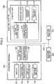
- Fig. 2 is a block diagram showing the electrical configuration of the operation terminal 100 and the electric shutter devices 200, 201, and 202.
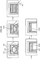
- Fig. 3 is a diagram schematically showing an example of a configuration of the electric shutter device 200.
- Fig. 4 is a diagram schematically showing an example of a configuration of the electric shutter device 201.
- the operation terminal 100 includes a display 101, a touch panel control section 102, a display control section 103, a storage section 104, a shutter control section 105, and a communication control section 106.
- the display 101 is formed from a touch panel display, for example, and displays a user interface that allows the user to operate the operation terminal 100. The user can input various operations to the operation terminal 100 by contacting the display 101.
- the touch panel control section 102 recognizes an operation performed on the display 101 by the user, interprets the content of the operation, and notifies the other constituent elements of the content of the operation. For example, if an object is displayed at a position on the display 101 tapped on by the user, the touch panel control section 102 judges that the object is selected by the user.
- GUI Graphic User Interface
- the display control section 103 generates a GUI of the operation terminal 100, and causes the display 101 to display the GUI.
- the storage section 104 stores information that is necessary for operation of the operation terminal 100 such as the type and the arrangement of the shutter which is the operation target.
- the shutter control section 105 generates a control command for each of the electric shutter devices 200, 201, and 202.
- the communication control section 106 controls communication between the operation terminal 100 and the electric shutter devices 200, 201, and 202.
- the communication control section 106 receives a request to transmit a variety of data from other blocks such as the shutter control section 105, and transmits the received data to the electric shutter devices 200, 201, and 202.
- the communication control section 106 receives data transmitted from the electric shutter devices 200, 201, and 202, and delivers the received data to relevant blocks such as the shutter control section 105.
- the display 101 may be a normal display rather than a touch panel display.
- the user may use an external input device such as a mouse (not shown) to input an instruction to select an object by moving a pointer displayed on the display 101 and clicking on a desired object. That is, in the embodiment, a series of operations performed by the user by contacting the display 101 may be replaced with operations of moving a pointer and clicking using an external input device such as a mouse.
- the electric shutter device 200 is provided in a garage 310.
- the electric shutter device 200 includes a control unit 210, a shutter 220 used as a gate to the garage 310, and so forth.
- the electric shutter device 200 is a device that enables the shutter 220 to be electrically opened and closed through a remote operation.
- the electric shutter device 201 is provided at a window 320.
- the electric shutter device 201 includes a control unit 210, a shutter 230 used as a storm sash, and so forth.
- the electric shutter device 201 is a device that enables the shutter 230 to be electrically opened and closed through a remote operation.
- the control unit 210 includes a drive section 211, a position sensor 212, a shutter control section 213, a communication control section 214, and an obstacle sensor 215.
- the drive section 211 includes a motor capable of rotating in forward and reverse directions, for example, to open and close the shutter 220.
- the position sensor 212 detects the open/close state (position) of the shutter 220.
- the position sensor 212 specifically detects the position of an end portion of the shutter 220, for example, as the open/close state of the shutter 220.
- the position sensor 212 includes an encoder attached to a rotary shaft of the motor of the drive section 211, the rotary shaft being coupled to the shutter 220.
- the position sensor 212 may count the number of steps of the stepping motor driven when opening and closing the shutter 220.
- the position sensor 212 may be any unit that can detect the open/close state of the shutter 220.
- the obstacle sensor 215 is provided on a right wall immediately outside the gate (shutter 220) of the garage 310, for example.
- a reflection plate is provided on a left wall immediately outside the gate (shutter 220) of the garage 310 at a position opposite to the obstacle sensor 215.
- the obstacle sensor 215 includes a light emitting section and a light receiving section, for example.
- the light receiving section of the obstacle sensor 215 receives light emitted from the light emitting section and reflected by the reflection plate.
- the obstacle sensor 215 is of an optical type, and thus can detect an obstacle when the obstacle appears, whether before the shutter 220 starts being closed or while the shutter 220 is being closed.
- the shutter control section 213 controls opening and closing of the shutter 220 of the electric shutter device 200 in accordance with a control command transmitted from the operation terminal 100.
- the shutter control section 213 requests the communication control section 214 to transmit the result of execution of the control command, the open/close state of the shutter 220 of the electric shutter device 200, and so forth to the operation terminal 100.
- the shutter control section 213 judges that an obstacle is interposed between the light emitting section and the reflection plate in the case where the light receiving section of the obstacle sensor 215 cannot receive the reflected light. If it is judged on the basis of the result of detection performed by the obstacle sensor 215 that there is an obstacle, the shutter control section 213 controls the drive section 211 so as not to start operation to close the shutter 220 if the shutter 220 has not started being closed, and so as to stop operation to close the shutter 220 if the shutter 220 is being closed.
- the communication control section 214 controls communication between the electric shutter device 200 and the operation terminal 100. In addition, the communication control section 214 receives a request to transmit a variety of data from the shutter control section 213, and transmits such data to the operation terminal 100. The communication control section 214 receives data transmitted from the operation terminal 100, and delivers the data to the shutter control section 213.
- the light emitting section and the light receiving section of the obstacle sensor 215 may be disposed on the left and right walls immediately outside the gate (shutter 220) of the garage 310 so as to oppose each other. In this case, the reflection plate is not required.
- the shutter control section 213 judges that an obstacle is interposed between the light emitting section and the light receiving section in the case where the light receiving section of the obstacle sensor 215 cannot receive light from the light emitting section.
- the obstacle sensor 215 is not limited to an optical type.
- the obstacle sensor 215 may be of a contact type.
- An obstacle sensor of a contact type detects a load applied to the drive section 211 which moves the shutter 220.
- the shutter control section 213 judges that there is an obstacle when an end portion of the shutter 220 moving in the closing direction contacts an obstacle and the load applied to the drive section 211 detected by the obstacle sensor of a contact type is increased.
- the shutter control section 213 can determine that there is an obstacle only after the shutter 220 starts moving in the closing direction and contacts an obstacle.
- the electric shutter device 200 may include both an obstacle sensor of an optical type and an obstacle sensor of a contact type as the obstacle sensor 215.
- the obstacle sensor 215 may be a sensor of any other type that can detect an obstacle.
- the electric shutter devices 201 and 202 are the same in electrical configuration as the electric shutter device 200 shown in Fig. 2 .
- the electric shutter device 200 is provided in the garage 310, for example, as described above.
- the electric shutter device 201 is disposed in a living room, for example.
- the electric shutter device 202 is disposed in a Japanese room, for example.
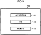
- Fig. 5 is a diagram showing a configuration example of the form of implementation of the operation terminal 100.
- the operation terminal 100 includes an application 401, an OS (Operating System) 402, a memory 403, and other hardware (not shown).
- OS Operating System
- the application 401 is application software for causing the information terminal to function as the operation terminal 100, and is executed by a processor of the operation terminal 100.
- the operation terminal 100 may read the application 401 from a computer readable recording medium to implement the application 401, or may download the application 401 from a network to implement the application 401.
- the OS 402 is basic software of the information terminal, and is executed by the processor of the operation terminal 100.
- the memory 403 is formed from a storage device such as a RAM and a ROM of the operation terminal 100, and stores a group of data included in the application 401.
- the processor of the operation terminal 100 executes the application 401 to embody the functions of the touch panel control section 102, the display control section 103, the storage section 104, the shutter control section 105, and the communication control section 106 shown in Fig. 2 .
- the processor of the operation terminal 100 executes the application 401 to cause the memory 403 to function as the storage section 104.
- the operation terminal 100 may be implemented by the application 401 alone, may be implemented by the application 401 and the OS 402, may be implemented by the application 401, the OS 402, and the memory 403, or may be implemented by the application 401, the OS 402, the memory 403, and other hardware (not shown).
- the operation terminal 100 according to the embodiment can be embodied.
- the processor and the storage device forming the information terminal for example, form a computer.
- One of a CPU, an FPGA, and an ASIC or a combination of two or more of these may be adopted as the processor.
- One of a ROM, a RAM, and a hard disk or a combination of two or more of these may be adopted as the storage device.
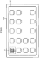
- Fig. 6 is a diagram showing a display example of a menu screen displayed on the display 101 for a case where a tablet is used as the operation terminal 100.
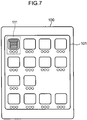
- Fig. 7 is a diagram showing a display example of a menu screen displayed on the display 101 for a case where a smartphone is used as the operation terminal 100.
- the menu screen displayed on the display 101 of the operation terminal 100 includes a shutter icon 111.
- the shutter icon 111 is an operation icon for starting the application 401 for electric shutter control.
- the shutter icon 111 includes an image schematically representing a shutter.
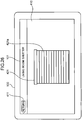
- Fig. 8 is a diagram showing an example of a shutter select screen 400 displayed on the display 101 of the operation terminal 100.
- the touch panel control section 102 senses the selection.
- the application 401 for electric shutter control is started, and the display control section 103 displays the shutter select screen 400 corresponding to the shutter icon 111 on the display 101 as shown in Fig. 8 .
- the shutter select screen 400 includes select buttons 405A, 405B, and 405C, a set button 406, and an end button 407.
- a text "SELECT SHUTTER" is affixed to the shutter select screen 400. The configuration allows the user to easily understand that the screen displayed on the display 101 is a screen for selecting an electric shutter device.
- the select button 405A is an operation button for selecting the electric shutter device 200 in the garage 310.
- the select button 405B is an operation button for selecting the electric shutter device 201 in the living room.
- the select button 405C is an operation button for selecting the electric shutter device 202 in the Japanese room.
- the select buttons 405A, 405B, and 405C are operation icons for displaying a shutter control screen for the electric shutter devices 200, 201, and 202, respectively.
- the set button 406 is an operation button for making a variety of settings.
- the set button 406 is used to associate a select button and a shutter as the operation target with each other, for example.
- the set button 406 is used to set a name given to a select button, for example.
- the end button 407 is an operation button for ending the application 401 for electric shutter control.
- the touch panel control section 102 senses the selection. Then, the application 401 for electric shutter control is ended, and the display control section 103 restores a state in which the menu screen is displayed on the display 101 as shown in Fig. 6 or 7 .
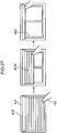
- Fig. 9 is a diagram showing an example of a shutter control screen 410 displayed on the display 101 of the operation terminal 100.
- the shutter control screen 410 shown in Fig. 9 is an operation screen that allows performing an open/close operation for the shutter 220 of the electric shutter device 200. As described above, the shutter 220 is used as a gate provided in the garage 310.
- the shutter control screen 410 includes a return button 411, and a shutter image 412 representing the shutter 220 of the electric shutter device 200.
- the shutter image 412 includes a shutter 412a.
- a text "GARAGE SHUTTER" is affixed to the shutter control screen 410 in Fig. 9 . This allows the user to easily understand that the screen is a control screen for a shutter used as a gate provided in the garage.
- the touch panel control section 102 senses the selection. Then, as shown in Fig. 9 , the display control section 103 displays the shutter control screen 410 corresponding to the select button 405A on the display 101.
- the touch panel control section 102 senses the selection. Then, the display control section 103 returns the display on the display 101 to the shutter select screen 400 shown in Fig. 8 .
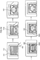
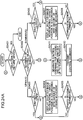
- Fig. 10 is a diagram showing an example of display on the shutter control screen 410 and an example of an operation by a contacting object 150 when opening the shutter 220.
- Fig. 11 is a diagram showing an example of display on the shutter control screen 410 and an example of an operation by the contacting object 150 when closing the shutter 220.
- the shutter image 412 in which the shutter 412a is fully closed is displayed (the upper left diagram of Fig. 10 ).
- the touch panel control section 102 senses an upward swipe operation by the contacting object 150 (for example, one finger of the user) on the shutter control screen 410 (the upper left diagram to the upper middle diagram of Fig. 10 ).
- the display control section 103 moves the shutter 412a within the shutter image 412 in the opening direction in accordance with movement of the contacting object 150 (the upper middle diagram of Fig. 10 ).
- the display control section 103 displays a vehicle image 413 representing a vehicle in the garage which has been hidden behind the shutter in a region corresponding to the shutter image 412 as the shutter 412a within the shutter image 412 is opened (the upper middle diagram of Fig. 10 ).
- the shutter 412a within the shutter image 412 may be provided in a first layer
- the vehicle image 413 may be provided in a second layer
- the order of priority for image display of the first layer may be made higher than that of the second layer.
- the touch panel control section 102 senses the swipe operation (the upper middle diagram to the upper right diagram of Fig. 10 ). Then, when the shutter 412a within the shutter image 412 is fully open, the display control section 103 erases the shutter 412a, and displays the vehicle image 413 representing the entire vehicle (the upper right diagram of Fig. 10 ).
- the shutter control section 105 When the touch panel control section 102 senses an upward swipe operation by the contacting object 150 on the shutter control screen 410, the shutter control section 105 generates a control command (corresponding to an example of the movement control command) for opening the shutter 220 of the electric shutter device 200. At this time, the shutter control section 105 decides the target position for the opening shutter on the basis of the amount of movement of the swipe operation by the contacting object 150.
- the shutter control section 105 decides a position at which the shutter is half open as the target position for the opening shutter.
- the display control section 103 renders the shutter 412a within the shutter image 412 half open as shown in the upper middle diagram of Fig. 10 . Display of the shutter 412a allows the user to easily understand the target position for the shutter.
- the shutter control section 105 decides a position at which the shutter is fully open as the target position for opening and closing of the shutter.
- the display control section 103 erases the shutter 412a within the shutter image 412 as shown in the upper right diagram of Fig. 10 to indicate that the target position for opening and closing of the shutter is the fully open position.
- the shutter control section 105 When the target position is decided, the shutter control section 105 generates a control command for opening the shutter 220 to the decided target position.
- the shutter control section 105 generates a control command corresponding to the decided target position. That is, the shutter control section 105 generates a control command (corresponding to an example of the distance control command) for opening the shutter 220 of the electric shutter device 200 for a distance corresponding to the amount of movement of the swipe operation by the contacting object 150.
- the communication control section 106 transmits the generated control command to the control unit 210 of the electric shutter device 200.
- the shutter control section 213 of the electric shutter device 200 receives the control command transmitted from the operation terminal 100 via the communication control section 214.
- the shutter control section 213 controls the drive section 211 to start operation of opening the shutter 220 in accordance with the received control command.
- the lower left diagram, the lower middle diagram, and the lower right diagram of Fig. 10 will be described later.
- Fig. 11 An operation of closing the shutter 220 of the electric shutter device 200 will be described with reference to Fig. 11 .
- the shutter image 412 in which the shutter is fully open is displayed, and the vehicle image 413 representing the entire vehicle in the garage is displayed in a region corresponding to the shutter image 412 (the upper left diagram of Fig. 11 ).
- the touch panel control section 102 senses a downward swipe operation by the contacting object 150 on the shutter control screen 410 (the upper left diagram to the upper middle diagram of Fig. 11 ).
- the display control section 103 moves the shutter 412a within the shutter image 412 in the closing direction in accordance with movement of the contacting object 150 (the upper middle diagram of Fig. 11 ). At this time, the display control section 103 hides the vehicle image 413 displayed in the region corresponding to the shutter image 412 behind the shutter 412a as the shutter 412a within the shutter image 412 is closed (the upper middle diagram of Fig. 11 ).
- the upper half of the vehicle image 413 is hidden behind the shutter 412a.
- the shutter 412a within the shutter image 412 may be provided in a first layer
- the vehicle image 413 may be provided in a second layer
- the order of priority for image display of the first layer may be made higher than that of the second layer.
- the touch panel control section 102 senses the swipe operation (the upper middle diagram to the upper right diagram of Fig. 11 ). Then, when the shutter 412a within the shutter image 412 is fully closed, the display control section 103 erases the vehicle image 413 (the upper right diagram of Fig. 11 ).
- the shutter control section 105 When the touch panel control section 102 senses a downward swipe operation by the contacting object 150 on the shutter control screen 410, the shutter control section 105 generates a control command (corresponding to an example of the movement control command) for closing the shutter 220 of the electric shutter device 200. At this time, the shutter control section 105 decides the target position for the closing shutter on the basis of the amount of movement of the swipe operation by the contacting object 150.
- the shutter control section 105 decides a position at which the shutter is half closed as the target position for the closing shutter.
- the display control section 103 renders the shutter 412a within the shutter image 412 half closed as shown in the upper middle diagram of Fig. 11 .
- the shutter control section 105 decides a position at which the shutter is fully closed as the target position for the closing shutter.
- the display control section 103 renders the shutter 412a within the shutter image 412 fully closed as shown in the upper right diagram of Fig. 11 .
- the shutter control section 105 When the target position is decided, the shutter control section 105 generates a control command for closing the shutter 220 to the decided target position.
- the shutter control section 105 generates a control command corresponding to the decided target position. That is, the shutter control section 105 generates a control command (corresponding to an example of the distance control command) for closing the shutter 220 of the electric shutter device 200 for a distance corresponding to the amount of movement of the swipe operation by the contacting object 150.
- the communication control section 106 transmits the generated control command to the control unit 210 of the electric shutter device 200.
- the shutter control section 213 of the electric shutter device 200 receives the control command transmitted from the operation terminal 100 via the communication control section 214.
- the shutter control section 213 controls the drive section 211 to start operation of closing the shutter 220 in accordance with the received control command.
- the lower left diagram, the lower middle diagram, and the lower right diagram of Fig. 11 will be described next.
- the shutter control section 213 controls the drive section 211 to start operation of opening and closing the shutter 220 in accordance with the received control command. Specifically, operation of opening the shutter 220 is started in Fig. 10 , and operation of closing the shutter 220 is started in Fig. 11 .
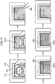
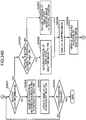
- the display control section 103 displays a schematic shutter movement image 500 representing the actual position of an end portion of the shutter 220 as overlapped on the shutter 412a within the shutter image 412 on the shutter control screen 410.
- the display control section 103 displays the schematic shutter movement image 500 in a region corresponding to the shutter image 412.
- the shutter control section 213 of the electric shutter device 200 When the drive section 211 starts open/close operation of the shutter, the shutter control section 213 of the electric shutter device 200 repeatedly acquires the result of detection of the position of the shutter 220 performed by the position sensor 212.
- the shutter control section 213 may acquire the result of detection of the position of the shutter 220 performed by the position sensor 212 at certain intervals (for example, 0.1 seconds).
- the shutter control section 213 generates positional information indicating the position of the shutter 220 on the basis of the result of detection of the position of the shutter 220 performed by the position sensor 212 at each acquisition of the detection result.
- the positional information may be a numerical value representing the proportion at which the shutter 220 is closed with the fully closed state defined as 100% and the fully open state defined as 0%, for example. In this case, the positional information on the shutter 220 which is halfway closed as in the upper middle diagram of Fig. 11 , for example, is 50%.
- the communication control section 214 transmits the generated positional information to the operation terminal 100.
- the shutter control section 213 controls the drive section 211 so as to stop open/close operation of the shutter 220.
- the display control section 103 of the operation terminal 100 receives the positional information indicating the position of the shutter 220 and transmitted from the electric shutter device 200 via the communication control section 106.
- the display control section 103 displays the schematic shutter movement image 500 representing the actual position of the end portion of the shutter 220 as overlapped on the vehicle image 413 on the shutter control screen 410 as shown in the lower left diagram of Fig. 10 , for example, on the basis of the received positional information.
- the display control section 103 displays the schematic shutter movement image 500 representing the actual position of the end portion of the shutter 220 as overlapped on the shutter 412a within the shutter image 412 on the shutter control screen 410 as shown in the lower left diagram of Fig. 11 , for example, on the basis of the received positional information.
- the position of a lower end 500D of the schematic shutter movement image 500 corresponds to the actual position of the end portion of the shutter 220 moving in the opening direction.
- the position of a lower end 500D of the schematic shutter movement image 500 corresponds to the actual position of the end portion of the shutter 220 moving in the closing direction.
- the display control section 103 may display the schematic shutter movement image 500 in a color that is different from those of the shutter 412a and the vehicle image 413 (red if the shutter 412a is brown and the vehicle image 413 is white, for example) and translucently on the display 101, for example.
- the schematic shutter movement image 500 and the vehicle image 413 may be synthesized by alpha blending.
- the schematic shutter movement image 500 and the shutter 412a may be synthesized by alpha blending.
- the schematic shutter movement image 500 and the vehicle image 413 can be distinguished from each other by color-coding.
- the schematic shutter movement image 500 and the shutter 412a can be distinguished from each other by color-coding.
- the schematic shutter movement image 500 is indicated by dots.
- the display control section 103 displays the schematic shutter movement image 500 as updated on the basis of the received positional information. For example, in the case where the positional information is received from the electric shutter device 200 every 0.1 seconds, the display control section 103 displays the schematic shutter movement image 500 as updated every 0.1 seconds.
- the actual position of the shutter 220 which gradually opens and closes is represented in the schematic shutter movement image 500 on the shutter control screen 410.
- the display control section 103 erases the schematic shutter movement image 500 from the shutter control screen 410 as shown in the lower right diagram of Fig. 10 and the lower right diagram of Fig. 11 .
- the schematic shutter movement image 500 between the state in which the shutter is fully closed and the state shown in the lower left diagram of Fig. 10 , the schematic shutter movement image 500 between the states shown in the lower left diagram and the lower middle diagram of Fig. 10 , and the schematic shutter movement image 500 between the states shown in the lower middle diagram and the lower right diagram of Fig. 10 are not shown.
- the schematic shutter movement image 500 between the state in which the shutter is fully open and the state shown in the lower left diagram of Fig. 11 , the schematic shutter movement image 500 between the states shown in the lower left diagram and the lower middle diagram of Fig. 11 , and the schematic shutter movement image 500 between the states shown in the lower middle diagram and the lower right diagram of Fig. 11 are not shown.
- the display control section 103 displays the schematic shutter movement image 500 representing the actual position of the end portion of the shutter 220 on the shutter control screen 410.
- the display control section 103 displays the shutter image 412 representing the target position for opening and closing of the shutter on the shutter control screen 410 in addition to the schematic shutter movement image 500.
- the schematic shutter movement image 500 corresponds to an example of the state information representing the position of the end portion of the shutter of the electric shutter device.
- the mode of representation of the actual position of the end portion of the shutter 220 on the shutter control screen 410 is not limited to the schematic shutter movement image 500. Another display example in which the actual position of the end portion of the shutter 220 is represented on the shutter control screen 410 will be described below.
- Fig. 12 is a diagram showing a display example of the shutter control screen 410 which is different from Fig. 10 and in which the actual position of the shutter is displayed when opening the shutter.
- Fig. 13 is a diagram showing a display example of the shutter control screen 410 which is different from Fig. 11 and in which the actual position of the shutter is displayed when closing the shutter.
- the upper left diagram, the upper middle diagram, and the upper right diagram of Fig. 12 are the same as the upper left diagram, the upper middle diagram, and the upper right diagram, respectively, of Fig. 10 .
- the upper left diagram, the upper middle diagram, and the upper right diagram of Fig. 13 are the same as the upper left diagram, the upper middle diagram, and the upper right diagram, respectively, of Fig. 11 .
- the display control section 103 of the operation terminal 100 receives the positional information indicating the position of the shutter 220 and transmitted from the electric shutter device 200 via the communication control section 106.
- the display control section 103 displays a position display mark 501 (the lower left diagram and the lower middle diagram of Fig. 12 ) representing the actual position of the end portion of the shutter 220 as overlapped on the vehicle image 413 on the shutter control screen 410 on the basis of the received positional information.
- the display control section 103 displays a position display mark 502 (the lower left diagram and the lower middle diagram of Fig. 13 ) representing the actual position of the end portion of the shutter 220 as overlapped on the shutter 412a within the shutter image 412 on the shutter control screen 410 on the basis of the received positional information.
- the position display mark 501 for a case where the shutter is opened is constituted of an arrow extending upward from the lower end of a region corresponding to the shutter image 412 on the shutter control screen 410.
- the position of an upper end 501U of the position display mark 501 corresponds to the actual position of the end portion of the shutter moving in the opening direction.
- the position display mark 502 for a case where the shutter is closed is constituted of an arrow extending downward from the upper end of a region corresponding to the shutter image 412 on the shutter control screen 410.
- the position of a lower end 502D of the position display mark 502 corresponds to the actual position of the end portion of the shutter moving in the closing direction.
- the display control section 103 displays the position display mark 501 (the lower left diagram to the lower middle diagram of Fig. 12 ) and the position display mark 502 (the lower left diagram to the lower middle diagram of Fig. 13 ) as updated on the basis of the received positional information. For example, in the case where the positional information is received from the electric shutter device 200 every 0.1 seconds, the display control section 103 displays the position display marks 501 and 502 as updated every 0.1 seconds.
- the actual position of the shutter which gradually opens and closes is represented by the position display marks 501 and 502 on the shutter control screen 410.
- the display control section 103 erases the position display marks 501 and 502 from the shutter control screen 410 as shown in the lower right diagram of Fig. 12 and the lower right diagram of Fig. 13 .
- the position display mark 501 between the state in which the shutter is fully closed and the state shown in the lower left diagram of Fig. 12 , the position display mark 501 between the states shown in the lower left diagram and the lower middle diagram of Fig. 12 , and the position display mark 501 between the states shown in the lower middle diagram and the lower right diagram of Fig. 12 are not shown.
- the position display mark 502 between the state in which the shutter is fully open and the state shown in the lower left diagram of Fig. 13 , the position display mark 502 between the states shown in the lower left diagram and the lower middle diagram of Fig. 13 , and the position display mark 502 between the states shown in the lower middle diagram and the lower right diagram of Fig. 13 are not shown.
- the display control section 103 displays an image representing the actual position of the end portion of the shutter 220 as overlapped on the shutter 412a within the shutter image 412 on the shutter control screen 410.
- the present disclosure is not limited thereto.
- the display control section 103 may not display an image representing the actual position of the end portion of the shutter 220 on the shutter control screen 410.
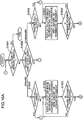
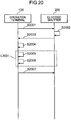
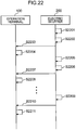
- Fig. 14 is a sequence diagram showing a process flow in the operation terminal 100 and the electric shutter device 200.
- the communication control section 106 of the operation terminal 100 transmits a request to acquire the present open/close state of the shutter 220 (for example, the position of the end portion of the shutter 220) to the electric shutter device 200 (S1401).
- the shutter control section 213 of the electric shutter device 200 acquires the open/close state of the shutter 220 from the position sensor 212 (S1402).
- the communication control section 214 Upon receiving a request from the shutter control section 213, the communication control section 214 transmits the open/close state of the shutter 220 to the operation terminal 100 (S1403).
- the display control section 103 of the operation terminal 100 receives the open/close state of the shutter 220 via the communication control section 106.
- the display control section 103 displays the shutter control screen 410 on the display 101 on the basis of the received open/close state of the shutter 220 (S1404). For example, in the case where the shutter 220 is fully open, the display control section 103 displays the shutter control screen 410 shown in the upper left diagram of Fig. 11 on the display 101.
- the touch panel control section 102 of the operation terminal 100 senses an operation (for example, an upward swipe operation, or a downward swipe operation) of the contacting object 150 performed by the user on the shutter control screen 410 (S1405).
- the display control section 103 of the operation terminal 100 moves the shutter 412a within the shutter image 412 so as to represent the target position for opening and closing of the shutter 220 in accordance with the amount of movement of the contacting object 150 (S1406).
- the display control section 103 displays the shutter control screen 410 shown in the upper middle diagram of Fig. 10 on the display 101. That is, the position of the shutter 412a within the shutter image 412 shown in the upper middle diagram of Fig. 10 is determined as the target position for opening of the shutter 220.
- the shutter control section 105 of the operation terminal 100 When the touch panel control section 102 senses that the contacting object 150 is moved away from the display 101, the shutter control section 105 of the operation terminal 100 generates a control command in accordance with the amount of movement of the swipe operation by the contacting object 150. Upon receiving a request from the shutter control section 105, the communication control section 106 transmits the control command generated by the shutter control section 105 to the electric shutter device 200 (S1407).
- the shutter control section 213 controls the drive section 211 on the basis of the control command to perform opening operation or closing operation of the shutter 220 (S1408).
- the shutter control section 213 detects the current open/close state of the shutter 220 (for example, the current position of the end portion of the shutter 220) using the position sensor 212.
- the shutter control section 213 generates positional information indicating the open/close state (position) of the shutter 220 on the basis of the detection result (S1409).
- the communication control section 214 Upon receiving a request from the shutter control section 213, the communication control section 214 transmits the generated positional information indicating the current open/close state of the shutter 220 to the operation terminal 100 (S1410).
- the display control section 103 of the operation terminal 100 displays the current open/close state of the shutter 220 on the shutter control screen 410 of the display 101 on the basis of the positional information received via the communication control section 106 (S1411).
- the display control section 103 displays the schematic shutter movement image 500 in the embodiment of Figs. 10 and 11 , displays the position display marks 501 in the embodiment of Fig. 12 , and displays the position display mark 502 in the embodiment of Fig. 13 .
- S1408 to S1411 included in L1402 are repeated until the open/close state of the shutter 220 (for example, the position of the end portion of the shutter 220) reaches the target position.
- the open/close state of the shutter 220 for example, the position of the end portion of the shutter 220
- display of the current open/close state of the shutter 220 is updated each time S1411 is executed.
- the communication control section 214 receives a request from the shutter control section 213, and transmits the result of control for the shutter 220 to the operation terminal 100 (S1412). The process is thus terminated.
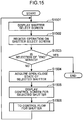
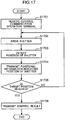
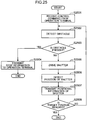
- Fig. 15 is a flowchart showing a process flow for the operation terminal 100 to control the electric shutter device 200.
- the display control section 103 displays the shutter select screen 400 on the display 101 (S1501). Subsequently, a user operation through contact of the contacting object 150 on the shutter select screen 400 is received (S1502). Next, the touch panel control section 102 judges whether or not the contact target for the contacting object 150 is the end button 407 (S1503).
- the touch panel control section 102 judges that the contact target is the end button 407 (YES in S1503), the flow is terminated.
- the touch panel control section 102 judges that the contact target is not the end button 407 (NO in S1503), on the other hand, the touch panel control section 102 judges a select button of the contact target.
- the display control section 103 acquires the current open/close state of a shutter corresponding to the judged select button from the electric shutter device (S1504). For example, if the touch panel control section 102 judges that the contact target is the select button 405A, the display control section 103 acquires the open/close state of the shutter 220 from the electric shutter device 200.
- the display control section 103 displays a shutter control screen corresponding to the select button of the contact target on the display 101 (S1505).
- the display control section 103 displays the shutter control screen 410 shown in Fig. 9 on the display 101.
- the process is advanced to a control flow for a shutter ( Figs. 16A and 16B ) (S1506). After that, the process returns to S1501.
- Figs. 16A and 16B are flowcharts showing a flow of the process (S1406 of Fig. 15 ) for the operation terminal 100 to generate and transmit a control command for controlling the shutter 220 of the electric shutter device 200.
- the touch panel control section 102 judges whether or not selection of the return button 411 by the contacting object 150 is sensed in the shutter control screen 410 (S1601). When selection of the return button 411 is sensed (YES in S1601), the flow is terminated. If selection of the return button 411 is not sensed (NO in S1601), the touch panel control section 102 judges whether or not upward or downward movement of the position of contact by the contacting object 150 is sensed (S1602).
- the process is advanced to S1603. If the touch panel control section 102 senses downward movement, the process is advanced to S1606. If upward or downward movement of the position of contact by the contacting object 150 is not sensed (NO in S1602), the process returns to S1601.
- the display control section 103 judges, on the basis of the open/close state acquired in S1504 of Fig. 15 , whether or not the shutter 220 of the electric shutter device 200 is fully open. If the shutter 220 is fully open (YES in S1603), the process returns to S1601. If the shutter 220 is not fully open (NO in S1603), the process is advanced to S1604.
- the display control section 103 moves the shutter 412a within the shutter image 412 displayed on the display 101 so as to represent the target position for the opening shutter 220 corresponding to the amount of the upward movement (upward swipe operation) of the contacting object 150 acquired from the touch panel control section 102 (S1604).
- the display control section 103 judges whether or not upward movement of the contacting object 150 is terminated (S1605). If the upward movement of the contacting object 150 is not terminated (NO in S1605), the process returns to S1604. If the upward movement of the contacting object 150 is terminated in S1605 (YES in S1605), on the other hand, the process is advanced to S1611.
- S1604 is executed until the upward movement is terminated.
- the shutter 412a within the shutter image 412 displayed on the display 101 is updated each time S1604 is executed.
- the shutter 412a within the shutter image 412 between the states shown in the upper left diagram and the upper middle diagram of Fig. 10 , and between the states shown in the upper middle diagram and the upper right diagram of Fig. 10 is not shown.
- the display control section 103 judges, on the basis of the open/close state acquired in S1504 of Fig. 15 , whether or not the shutter 220 of the electric shutter device 200 is fully closed. If the shutter 220 is fully closed (YES in S1606), the process returns to S1601. If the shutter 220 is not fully closed (NO in S1606), the process is advanced to S1607.
- the display control section 103 moves the shutter 412a within the shutter image 412 displayed on the display 101 so as to represent the target position for the closing shutter 220 corresponding to the amount of the downward movement (downward swipe operation) of the contacting object 150 acquired from the touch panel control section 102 (S1607).
- the display control section 103 judges whether or not downward movement of the contacting object 150 is terminated (S1608). If the downward movement of the contacting object 150 is not terminated (NO in S1608), the process returns to S1607. If the downward movement of the contacting object 150 is terminated in S1608 (YES in S1608), on the other hand, the process is advanced to S1611.
- S1607 is executed until the downward movement is terminated.
- the shutter 412a within the shutter image 412 displayed on the display 101 is updated each time S1607 is executed.
- the shutter 412a within the shutter image 412 between the states shown in the upper left diagram and the upper middle diagram of Fig. 11 and between the states shown in the upper middle diagram and the upper right diagram of Fig. 11 is not shown.
- the shutter control section 105 In S1611, the shutter control section 105 generates a control command for opening and closing the shutter 220 to the target position corresponding to the amount of the upward movement or the downward movement of the contacting object 150 acquired from the touch panel control section 102. Subsequently, the communication control section 106 transmits the control command generated by the shutter control section 105 to the electric shutter device 200 (S1612).
- the communication control section 106 receives positional information indicating the position (open/close state) of the shutter 220, and delivers the received positional information to the display control section 103 and the shutter control section 105 (S1613). Then, the display control section 103 displays the position of the shutter 220 on the basis of the received positional information (S1614). In S1614, the display control section 103 displays the schematic shutter movement image 500 in the embodiment of Figs. 10 and 11 , displays the position display mark 501 in the embodiment of Fig. 12 , and displays the position display mark 502 in the embodiment of Fig. 13 .
- the shutter control section 105 judges, on the basis of the positional information received in S1613, whether or not the shutter 220 has reached the target position (S1615). If the shutter 220 has not reached the target position in S1615 (NO in S1615), the process returns to S1613. If the shutter 220 has reached the target position in S1615 (YES in S1615), on the other hand, the communication control section 106 receives the control result transmitted from the electric shutter device 200, and delivers the received control result to the shutter control section 105 (S1615). The flow is thus terminated.
- S1604 is executed until the shutter 220 reaches the target position.
- the position of the shutter 220 displayed on the shutter control screen 410 of the display 101 is updated each time S1614 is executed (for example, at intervals of 0.1 seconds).
- Fig. 17 is a flowchart showing a process flow in the electric shutter device 200.
- the communication control section 214 of the electric shutter device 200 receives a control command for opening and closing a shutter transmitted from the operation terminal 100, and delivers the control command to the shutter control section 213 (S1701).
- the shutter control section 213 controls the drive section 211 in accordance with the received control command to drive the shutter 220 (S1702).
- the shutter control section 213 acquires the result of detection of the open/close state (position) of the shutter 220 from the position sensor 212 (S1703).
- the shutter control section 213 generates positional information indicating the position of the shutter 220 on the basis of the result of detection of the open/close state of the shutter 220, and the communication control section 214 transmits the generated positional information to the operation terminal 100 (S1704).
- the shutter control section 213 judges, on the basis of the acquired detection result, whether or not the shutter 220 has reached the target position indicated by the control command (S1705). If the shutter 220 has not reached the target position (NO in S1705), the process returns to S1702. If the shutter 220 has reached the target position in S1705 (YES in S1705), on the other hand, the communication control section 214 receives a request from the shutter control section 213, and transmits the control result to the operation terminal 100 (S1706). The flow is thus terminated.
- S1704 is executed until the shutter 220 reaches the target position.
- the positional information indicating the position of the shutter 220 is transmitted to the operation terminal 100 each time S1704 is executed (for example, at intervals of 0.1 seconds).
- the shutter control section 213 judges the presence or absence of an obstacle on the basis of the result of detection performed by the obstacle sensor 215. Then, if it is judged that there is an obstacle, the shutter control section 213 controls the drive section 211 so as not to start operation to close the shutter 220 if the shutter 220 has not started being closed, and so as to stop operation to close the shutter 220 if the shutter 220 is being closed. Display on the display 101 in this case will be described.
- Fig. 18 is a diagram showing a display example of the shutter control screen 410 for a case where an obstacle is detected.
- the upper left diagram, the upper middle diagram, and the upper right diagram of Fig. 18 are the same as the upper left diagram, the upper middle diagram, and the upper right diagram, respectively, of Fig. 11 .
- the display control section 103 controls display on the shutter control screen 410 in the same manner as described with reference to Fig. 11 .
- the vehicle image 413 is displayed in a region corresponding to the shutter image 412 (the upper left diagram of Fig. 18 ).
- the touch panel control section 102 senses a downward swipe operation by the contacting object 150.
- the display control section 103 moves the shutter 412a within the shutter image 412 in the closing direction, that is, downward (corresponding to an example of the first direction) in accordance with the amount of movement of the swipe operation (the upper middle diagram of Fig. 18 ).
- the shutter 412a within the shutter image 412 is fully closed, and displayed on the shutter control screen 410 as the target position for opening and closing of the shutter (the upper right diagram of Fig. 18 ).
- the shutter control section 213 controls the drive section 211 so as to stop operation of the shutter 220, and generates stop information.
- the stop information includes information indicating that operation of the shutter 220 has been stopped.
- the stop information also includes information indicating the position at which the shutter 220 is stopped.
- the communication control section 214 Upon receiving a request from the shutter control section 213, the communication control section 214 transmits the stop information generated by the shutter control section 213 to the operation terminal 100.
- the display control section 103 of the operation terminal 100 returns the fully closed shutter 412a (the upper right diagram of Fig. 18 ) within the shutter image 412 displayed on the shutter control screen 410 in the opening direction, that is, upward (corresponding to an example of the second direction) to a half open position as indicated by an arrow mark 415 in the lower left diagram of Fig. 18 .
- the arrow mark 415 is provided to indicate that the shutter 412a within the shutter image 412 is returned in one stroke from the fully closed position to the half open position.
- the arrow mark 415 is not displayed on the shutter control screen 410.
- the display control section 103 finely vertically vibrates the shutter 412a within the shutter image 412.
- the display control section 103 repeatedly moves a lower end 412D of the shutter 412a within the shutter image 412 alternately upward and downward.
- the display state of the shutter control screen 410 alternately transitions between the states shown in the lower left diagram and the lower right diagram of Fig. 18 .
- the shutter 412a within the shutter image 412 which has been fully closed as shown in the upper right diagram of Fig. 18 by downward movement of the contacting object 150 is immediately returned to a half open position as shown in the lower left diagram of Fig. 18 . Therefore, the shutter 412a within the shutter image 412 bounces. Thus, the user can be alerted by the vibration of the shutter 412a within the shutter image 412 that operation of the shutter 220 is not normal, rather than that the display 101 is out of order.
- the display control section 103 does not display an image (the schematic shutter movement image 500 in Fig. 11 , and the position display mark 502 in Fig. 13 ) representing the actual position of the shutter 220.
- the width of the vibration may be a width of 5% in terms of the numerical value of the positional information, for example.
- the width of the vibration may be decided as such a value that allows the user to definitely recognize the vibration.
- the period of the vibration may be 0.5 seconds, for example.
- the period of the vibration may be decided as such a value that allows the user to easily see the vibration.
- Fig. 19 is a diagram showing a display example of the shutter control screen 401 that is different from Fig. 18 for a case where an obstacle is detected.
- the upper left diagram, the upper middle diagram, and the upper right diagram of Fig. 19 are the same as the upper left diagram, the upper middle diagram, and the upper right diagram, respectively, of Fig. 11 ( Fig. 18 ).
- the display control section 103 when the stop information is received from the electric shutter device 200 via the communication control section 106, the display control section 103 returns the fully closed shutter 412a (the upper right diagram of Fig. 19 ) within the shutter image 412 displayed on the shutter control screen 410 to a half open position (the lower left diagram of Fig. 19 ).
- the display control section 103 displays an alerting mark 600 on the shutter control screen 410 (the lower left diagram of Fig. 19 ). Furthermore, as in the embodiment of Fig. 18 , the display control section 103 finely vertically vibrates the shutter 412a within the shutter image 412 as indicated by a vibration mark 601 (the lower right diagram of Fig. 19 ).
- the vibration mark 601 in the lower right diagram of Fig. 19 is intended to represent the fine vertical vibration of the shutter 412a within the shutter image 412. Upward and downward arrows and wavy lines included in the vibration mark 601 are not displayed on the shutter control screen 410. In Fig. 19 , in addition, the alerting mark 600 is displayed, and therefore the display control section 103 may not vibrate the shutter 412a within the shutter image 412.
- Figs. 20 to 23 are sequence diagrams showing a process flow in the operation terminal 100 and the electric shutter device 200 for a case where obstacle detection is taken into consideration.
- a first pattern corresponds to a sequence in which an obstacle is not detected.
- the shutter 220 is closed to the target position.
- the sequence diagram of Fig. 20 is followed by the sequence diagram of Fig. 21 .
- a second pattern corresponds to a sequence in which an obstacle is detected while the shutter 220 is being closed.
- operation of closing the shutter 220 is started.
- the shutter 220 stops being driven, and an alarm indication of the obstacle is displayed.
- the obstacle sensor 215 is of an optical type
- the second pattern corresponds to a case where an obstacle appears when the shutter 220 is closed halfway.
- the sequence for the second pattern is used.
- the sequence diagram of Fig. 20 is followed by the sequence diagram of Fig. 22 .
- a third pattern corresponds to a sequence in which an obstacle is first detected by the obstacle sensor 215 of an optical type.
- an alarm indication to the obstacle is displayed before the shutter 220 is closed, and operation of closing the shutter 220 is not started.
- the sequence for the third pattern is not used.
- the sequence diagram of Fig. 20 is followed by the sequence diagram of Fig. 23 .
- Fig. 20 is common to the first to third patterns.
- S2001 to S2007 of Fig. 20 are the same as S1401 to S1407, respectively, of Fig. 14 .
- L2001 including S2005 and S2006 of Fig. 20 are the same as L1401 including S1405 and S1406 of Fig. 20 . It should be noted, however, that it is assumed that in the first to third patterns, the position of the shutter 220 detected in S2002 of Fig. 20 is not the fully closed position, the operation performed in S2005 is a downward swipe operation, and the control command transmitted in S2007 is a command for closing the shutter 220.
- the shutter control section 213 of the electric shutter device 200 receives a control command transmitted in S2007 of Fig. 20 via the communication control section 214, and controls the drive section 211 on the basis of the received control command so as to close the shutter 220 (S2101).
- the shutter control section 213 judges the current open/close state of the shutter 220 using the result of detection performed by the position sensor 212, and generates positional information indicating the open/close state (position) of the shutter 220 (S2102).
- the communication control section 214 transmits the generated positional information indicating the current open/close state of the shutter 220 to the operation terminal 100 (S2103).
- the display control section 103 of the operation terminal 100 displays the current open/close state of the shutter 220 on the shutter control screen 410 of the display 101 on the basis of the positional information received via the communication control section 106 (S2104).
- S2105 to S2108 are the same as S2101 to S2104, respectively. Operation in S2101 to S2104 is repeated every certain period (for example, 0.1 seconds). Then, in S2109, the shutter control section 213 detects on the basis of the result of detection performed by the position sensor 212 that the shutter 220 has reached the target position, and stops operation of the drive section 211. Next, upon receiving a request from the shutter control section 213, the communication control section 214 transmits the result of control for the shutter 220 to the operation terminal 100 (S2110).
- the shutter control section 213 of the electric shutter device 200 receives a control command transmitted in S2007 of Fig. 20 via the communication control section 214, and controls the drive section 211 on the basis of the received control command so as to close the shutter 220 (S2201).
- S2201 to S2204 are the same as S2101 to S2104, respectively.
- Subsequent S2205 to S2208 are also the same as S2101 to S2104, respectively. Operation in S2201 to S2204 is repeated every certain period (for example, 0.1 seconds).
- the shutter control section 213 of the electric shutter device 200 judges on the basis of the result of detection performed by the obstacle sensor 215 that there is an obstacle. In addition, the shutter control section 213 stops operation of the drive section 211.
- the communication control section 214 transmits stop information indicating that drive of the shutter 220 has been stopped because of detection of an obstacle to the operation terminal 100.
- the display control section 103 of the operation terminal 100 displays an image alerting the user on the shutter control screen 410 of the display 101 on the basis of the stop information received via the communication control section 106.
- the display control section 103 vertically vibrates the shutter 412a within the shutter image 412.
- the display control section 103 displays the alerting mark 600 in a region corresponding to the shutter image 412.
- the shutter control section 213 of the electric shutter device 200 receives the control command transmitted in S2007 of Fig. 20 via the communication control section 214. In subsequent S2301, however, the shutter control section 213 judges on the basis of the result of detection performed by the obstacle sensor 215 that there is an obstacle. Thus, the shutter control section 213 does not cause operation of the drive section 211 although a control command has been received. Subsequent S2302 and S2303 are the same as S2210 and S2211, respectively, of Fig. 22 .
- Figs. 24A and 24B are flowcharts showing a flow of the process (S1406 of Fig. 15 ) for the operation terminal 100 to control the shutter 220 of the electric shutter device 200 for a case where an obstacle is taken into consideration.
- S2401 to S2408 of Fig. 24A are the same as S1601 to S1608, respectively, of Fig. 16A .
- S2411 and S2412 of Fig. 24A are the same as S1611 and S1612, respectively, of Fig. 16B .
- the shutter control section 105 judges whether or not the communication control section 106 has received stop information from the electric shutter device 200. If the communication control section 106 has not received the stop information in S2421 (NO in S2421), the process is advanced to S2422. If the communication control section 106 has received the stop information in S2421 (YES in S2421), on the other hand, the process is advanced to S2425.
- the communication control section 106 receives positional information indicating the position of the shutter 220, and delivers the received positional information to the display control section 103 and the shutter control section 105 (S2422). Then, the display control section 103 displays the position of the shutter 220 on the shutter control screen 410 on the basis of the received positional information (S2423). In S2423, the display control section 103 displays the schematic shutter movement image 500 in the embodiment of Figs. 10 and 11 , displays the position display mark 501 in the embodiment of Fig. 12 , and displays the position display mark 502 in the embodiment of Fig. 13 .
- the shutter control section 105 judges, on the basis of the positional information received in S2422, whether or not the shutter 220 has reached the target position (S2424). If the shutter 220 has not reached the target position in S2424 (NO in S2424), the process returns to S2421. If the shutter 220 has reached the target position in S2424 (YES in S2424), on the other hand, the flow is terminated.
- the display control section 103 judges, on the basis of the positional information received in S2422 or S1504 of Fig. 15 , whether or not the actual shutter is closed to a position at which the shutter is closed beyond 70% (S2425). If the actual shutter is closed to a position at which the shutter is closed beyond 70% (YES in S2425), the display control section 103 returns the shutter 412a within the shutter image 412 being displayed to a position of 70% (S2426), and the process is advanced to S2428.
- the display control section 103 returns the shutter 412a within the shutter image 412 being displayed in the opening direction (corresponding to an example of the second direction) by an amount of 30% (corresponding to an example of the second predetermined amount).
- the display control section 103 returns the shutter 412a within the shutter image 412 being displayed to the actual position (S2427), and the process is advanced to S2428. If the actual shutter 220 is closed to a position of 60%, for example, the display control section 103 returns the shutter 412a within the shutter image 412 being displayed in the opening direction (corresponding to an example of the second direction) by an amount of 40% (corresponding to an example of the first predetermined amount).
- the display control section 103 displays an alerting mark 600 on the shutter control screen 410.
- the display control section 103 finely vertically vibrates the position of the shutter 412a within the shutter image 412 (S2429), and the process returns to S2401.
- S2428 may be omitted.
- S2429 may be omitted.
- the loop of S2421, S2422, S2423, and S2424 of Fig. 24B corresponds to a case where there is not an obstacle.
- the path of S2421, S2425, S2426, S2428, and S2429 of Fig. 24B corresponds to a case where an obstacle is detected when the shutter 220 is closed to a position at which the shutter 220 is closed beyond a predetermined reference amount (in Fig. 24B , 70%, for example).
- the path of S2421, S2425, S2427, S2428, and S2429 of Fig. 24B corresponds to a case where an obstacle is detected when the shutter 220 is closed to a position at which the shutter 220 is closed by the predetermined reference amount (in Fig. 24B , 70%, for example) or less (including before the shutter 220 starts moving).
- Fig. 24B if the actual shutter 220 is not closed to a position at which the shutter is closed beyond 70% (NO in S2425), the display control section 103 returns the shutter 412a within the shutter image 412 being displayed to the actual position (S2427). That is, the display control section 103 returns the shutter 412a within the shutter image 412 to a position at which the shutter 220 has been stopped because of detection of an obstacle.
- the width of the return of the shutter 412a within the shutter image 412 on the shutter control screen 410 would be small in the case where the obstacle is small. As a result, the user might not notice that the shutter 412a within the shutter image 412 was returned.
- the display control section 103 returns the shutter 412a within the shutter image 412 being displayed to a position of the predetermined reference amount (in Fig. 24B , 70%, for example) (S2426). This makes it easier for the user to notice that the shutter 412a within the shutter image 412 has been returned.
- the predetermined reference amount of 70% is exemplary, and the predetermined reference amount may have a different value such as 60%.
- the shutter 412a within the shutter image 412 being displayed is returned to a position of 70% (S2426) or the actual position at which the shutter 220 has been stopped (S2427), depending on the actual position at which the shutter 220 has been stopped.
- the present disclosure is not limited thereto.
- the shutter 412a within the shutter image 412 may be returned to a half open position (50%) without exception irrespective of the actual position at which the shutter 220 has been stopped.
- Fig. 25 is a flowchart showing a process flow in the electric shutter device 200 for a case where an obstacle is taken into consideration.
- the communication control section 214 of the electric shutter device 200 receives a control command transmitted from the operation terminal 100, and delivers the control command to the shutter control section 213 (S2501). Then, the shutter control section 213 acquires the result of detection performed by the obstacle sensor 215 (S2502). Next, the shutter control section 213 judges, on the basis of the result of detection performed by the obstacle sensor 215, whether or not there is an obstacle (S2503). If there is an obstacle in S2503 (YES in S2503), the process is advanced to S2504. If there is not an obstacle (NO in S2503), the process is advanced to S2505.
- the shutter control section 213 controls the drive section 211 so as to stop the shutter 220 if the shutter 220 is moved.
- the communication control section 214 transmits stop information indicating that movement of the shutter has been stopped to the operation terminal 100. Then, the flow is terminated.
- S2505 to S2507 are the same as S1702 to S1704 of Fig. 17 .
- the shutter control section 213 judges, on the basis of the position of the shutter 220 acquired in S2506, whether or not the shutter 220 has reached the target position indicated by the control command (S2508). If the shutter 220 has not reached the target position (NO in S2508), the process returns to S2502. If the shutter 220 has reached the target position in S2508 (YES in S2508), on the other hand, the flow is terminated.
- Fig. 26 is a diagram showing an example, different from Fig. 9 , of a shutter control screen 410 displayed on the display 101 of the operation terminal 100.
- the shutter control screen 410 shown in Fig. 26 is an operation screen that allows performing an open/close operation for the shutter 230 of the electric shutter device 201.
- the shutter 230 is used as a storm sash provided at the window 320.
- the shutter control screen 410 includes a return button 411, and a shutter image 421 representing the shutter 230 of the electric shutter device 201.
- the shutter image 421 includes a shutter 421a.
- a text "LIVING ROOM SHUTTER" is affixed to the shutter control screen 410 in Fig. 26 . This allows the user to easily understand that the screen is a control screen for a shutter used as a storm sash provided at the window.
- the touch panel control section 102 senses the selection. Then, as shown in Fig. 26 , the display control section 103 displays the shutter control screen 410 corresponding to the select button 405B on the display 101.
- the touch panel control section 102 senses the selection. Then, the display control section 103 returns the display on the display 101 to the shutter select screen 400 shown in Fig. 8 .
- Fig. 27 is a diagram showing an example of display on the shutter control screen 410 and an example of an operation by a contacting object 150 when opening the shutter 230.
- Fig. 28 is a diagram showing an example of display on the shutter control screen 410 and an example of an operation by the contacting object 150 when closing the shutter 230.
- FIG. 27 An operation of opening the shutter 230 of the electric shutter device 201 will be described with reference to Fig. 27 .
- the shutter image 412 in which the shutter 412a is fully closed is displayed (the left diagram of Fig. 27 ).
- the touch panel control section 102 senses an upward swipe operation by the contacting object 150 (for example, one finger of the user) on the shutter control screen 410 (the left diagram to the middle diagram of Fig. 27 ).
- the display control section 103 moves the shutter 421a within the shutter image 421 in the opening direction in accordance with movement of the contacting object 150 (the middle diagram of Fig. 27 ). At this time, the display control section 103 displays a window image 422 representing the window 320 which has been hidden behind the shutter in a region corresponding to the shutter image 421 as the shutter 421a within the shutter image 421 is opened.
- the shutter 421a within the shutter image 421 may be provided in a first layer
- the window image 422 may be provided in a second layer
- the order of priority for image display of the first layer may be made higher than that of the second layer.
- the touch panel control section 102 senses the swipe operation (the middle diagram to the right diagram of Fig. 27 ). Then, when the shutter 421a within the shutter image 421 is fully open, the display control section 103 erases the shutter 421a, and displays the window image 422 representing the entire window (the right diagram of Fig. 27 ).
- the shutter control section 105 When the touch panel control section 102 senses an upward swipe operation by the contacting object 150 on the shutter control screen 410, the shutter control section 105 generates a control command (corresponding to an example of the movement control command) for opening the shutter 230 of the electric shutter device 201. At this time, the shutter control section 105 decides the target position for the opening shutter on the basis of the amount of movement of the swipe operation by the contacting object 150.
- the shutter control section 105 decides a position at which the shutter is half open as the target position for the opening shutter.
- the display control section 103 renders the shutter 421a within the shutter image 421 half open as shown in the middle diagram of Fig. 27 . Display of the shutter 421a allows the user to easily understand the target position for the shutter.
- the shutter control section 105 decides a position at which the shutter is fully open as the target position for opening and closing of the shutter.
- the display control section 103 erases the shutter 421a within the shutter image 421 as shown in the right diagram of Fig. 27 to indicate that the target position for opening and closing of the shutter is the fully open position.
- the shutter control section 105 When the target position is decided, the shutter control section 105 generates a control command for opening the shutter 230 to the decided target position.
- the shutter control section 105 generates a control command corresponding to the decided target position. That is, the shutter control section 105 generates a control command (corresponding to an example of the distance control command) for opening the shutter 230 of the electric shutter device 201 for a distance corresponding to the amount of movement of the swipe operation by the contacting object 150.
- the communication control section 106 transmits the generated control command to the control unit 210 of the electric shutter device 201.
- the shutter control section 213 of the electric shutter device 201 receives the control command transmitted from the operation terminal 100 via the communication control section 214.
- the shutter control section 213 controls the drive section 211 to start operation of opening the shutter 230 in accordance with the received control command.
- Fig. 28 An operation of closing the shutter 230 of the electric shutter device 201 will be described with reference to Fig. 28 .
- the shutter image 421 in which the shutter is fully open is displayed, and the window image 422 representing the entire window is displayed in a region corresponding to the shutter image 421 (the left diagram of Fig. 28 ).
- the touch panel control section 102 senses a downward swipe operation by the contacting object 150 on the shutter control screen 410 (the left diagram to the middle diagram of Fig. 28 ).
- the display control section 103 moves the shutter 421a within the shutter image 421 in the closing direction in accordance with movement of the contacting object 150 (the middle diagram of Fig. 28 ). At this time, the display control section 103 hides the window image 422 displayed in the region corresponding to the shutter image 421 behind the shutter 421a as the shutter 421a within the shutter image 421 is closed (the middle diagram of Fig. 28 ).
- the upper half of the window image 422 is hidden behind the shutter 421a.
- the shutter 421a within the shutter image 421 may be provided in a first layer
- the window image 422 may be provided in a second layer
- the order of priority for image display of the first layer may be made higher than that of the second layer.
- the touch panel control section 102 senses the swipe operation (the middle diagram to the right diagram of Fig. 28 ). Then, when the shutter 421a within the shutter image 421 is fully closed, the display control section 103 erases the window image 422 (the right diagram of Fig. 28 ).
- the shutter control section 105 When the touch panel control section 102 senses a downward swipe operation by the contacting object 150 on the shutter control screen 410, the shutter control section 105 generates a control command (corresponding to an example of the movement control command) for closing the shutter 230 of the electric shutter device 201. At this time, the shutter control section 105 decides the target position for the closing shutter on the basis of the amount of movement of the swipe operation by the contacting object 150.
- the shutter control section 105 decides a position at which the shutter is half closed as the target position for the closing shutter.
- the display control section 103 renders the shutter 421a within the shutter image 421 half closed as shown in the middle diagram of Fig. 28 .
- the shutter control section 105 decides a position at which the shutter is fully closed as the target position for the closing shutter.
- the display control section 103 renders the shutter 421a within the shutter image 421 fully closed as shown in the right diagram of Fig. 28 .
- the shutter control section 105 When the target position is decided, the shutter control section 105 generates a control command for closing the shutter 230 to the decided target position.
- the shutter control section 105 generates a control command corresponding to the decided target position. That is, the shutter control section 105 generates a control command (corresponding to an example of the distance control command) for closing the shutter 230 of the electric shutter device 201 for a distance corresponding to the amount of movement of the swipe operation by the contacting object 150.
- the communication control section 106 transmits the generated control command to the control unit 210 of the electric shutter device 201.
- the shutter control section 213 of the electric shutter device 201 receives the control command transmitted from the operation terminal 100 via the communication control section 214.
- the shutter control section 213 controls the drive section 211 to start operation of closing the shutter 220 in accordance with the received control command.
- the shutter control section 213 controls the drive section 211 to start operation of opening and closing the shutter 230 in accordance with the received control command. Specifically, operation of opening the shutter 230 is started in Fig. 27 , and operation of closing the shutter 230 is started in Fig. 28 . At this time, actual motion of the shutter 230 is slower than motion of the shutter 421a within the shutter image 421 displayed on the shutter control screen 410.
- the display control section 103 may display an image representing the actual position of an end portion of the shutter 230 as overlapped on the shutter 421a within the shutter image 421 on the shutter control screen 410.
- the present disclosure provides a useful control method for controlling an electric shutter device connected to a network.
Landscapes
- Engineering & Computer Science (AREA)
- General Engineering & Computer Science (AREA)
- Theoretical Computer Science (AREA)
- Human Computer Interaction (AREA)
- Physics & Mathematics (AREA)
- General Physics & Mathematics (AREA)
- Structural Engineering (AREA)
- Computer Networks & Wireless Communication (AREA)
- Signal Processing (AREA)
- Civil Engineering (AREA)
- Architecture (AREA)
- Automation & Control Theory (AREA)
- Selective Calling Equipment (AREA)
- Operating, Guiding And Securing Of Roll- Type Closing Members (AREA)
- User Interface Of Digital Computer (AREA)
- Power-Operated Mechanisms For Wings (AREA)
- Telephone Function (AREA)
- Telephonic Communication Services (AREA)
- Remote Monitoring And Control Of Power-Distribution Networks (AREA)
Claims (10)
- Procédé de contrôle d'un appareil d'information (100), l'appareil d'information (100) comprenant un affichage à panneau tactile (101) et étant connecté à un réseau (300), un dispositif de volet électrique (200) étant contrôlé par le réseau (300), le dispositif de volet électrique (200) étant capable d'ouvrir et de fermer un volet (220, 230) par une opération à distance,
le procédé amenant un ordinateur de l'appareil d'information (100) :à afficher une icône d'opération (111) sur un écran d'affichage de l'appareil d'information (100), l'icône d'opération amenant un écran d'opération (410) pour le dispositif de volet électrique (200) à être affiché ;à afficher l'écran d'opération (410) pour le dispositif de volet électrique (200) lorsqu'une sélection de l'icône d'opération est détectée, l'écran d'opération (410) comprenant une image de volet (412, 421) représentant le volet (220, 230) du dispositif de volet électrique (200) ; etlorsqu'une opération de balayage est détectée sur l'écran d'opération (410), à émettre vers le réseau (300) une commande de contrôle à distance pour déplacer le volet (220, 230) du dispositif de volet électrique (200) dans une direction de balayage de l'opération de balayage, conformément à une quantité de mouvement dans la direction de balayage de l'opération de balayage ; etlorsque l'opération de balayage est détectée sur l'écran de opération (410) pour émettre la commande de contrôle à distance vers le réseau, l'affichage de l'image de volet (412, 421) sur l'écran de opération (410) étant variée en une image dans laquelle le volet (220, 230) du dispositif de volet électrique (200) est déplacé conformément à la quantité de mouvement dans la direction de balayage de l'opération de balayage, l'image de volet (412, 421) sur l'écran de opération (410) étant déplacée sur une distance correspondant à une distance d'opération de l'opération de balayage,des informations de position indiquant une position du volet (220, 230) du dispositif de volet électrique (200) étant reçues par le biais du réseau (300),des informations d'état représentant une position d'une partie d'extrémité du volet (220, 230) du dispositif de volet électrique (200) étant affichées superposées sur l'image de volet (412, 421), dans une région correspondant à l'image de volet (412, 421) conformément aux informations de position reçues. - Procédé selon la revendication 1, dans lequel
un mouvement du volet (220, 230) du dispositif de volet électrique (200) comprend un mouvement pour ouvrir le volet (220, 230) du dispositif de volet électrique (200) ou un mouvement pour fermer le volet (220, 230) du dispositif de volet électrique (200). - Procédé selon l'une quelconque des revendications 1 à 2, dans lequel
le dispositif de volet électrique (200) comprend le volet (220, 230) qui s'ouvre et se ferme dans une direction. - Procédé selon la revendication 1, dans lequel
l'image de volet (421) comprend une image représentant le volet (230) du dispositif de volet électrique (200) utilisé sous la forme d'un volet à guillotine disposé au niveau d'une fenêtre (320), et
dans un cas où le volet (230) représenté dans l'image de volet (421) est déplacé dans une direction d'ouverture, une image de fenêtre (422) représentant la fenêtre (320) qui a été cachée derrière le volet (230) du dispositif de volet électrique (200) est affichée dans une région correspondant à l'image de volet (421). - Procédé selon la revendication 4, dans lequel
dans un cas où le volet (230) représenté dans l'image de volet (421) est déplacé dans une direction de fermeture, l'image de fenêtre (422) est cachée derrière le volet (230) représenté dans l'image de volet (421). - Procédé selon la revendication 1, dans lequel
l'image de volet (412) comprend une image représentant le volet (220) du dispositif de volet électrique (200) utilisé sous la forme d'un portail disposé dans un garage (310), et
dans un cas où le volet (220) représenté dans l'image de volet (412) est déplacé dans une direction d'ouverture, une image de véhicule (413) représentant un véhicule dans le garage (310) qui a été caché derrière le volet (220) du dispositif de volet électrique (200) est affichée dans une région correspondant à l'image de volet (412). - Procédé selon la revendication 6, dans lequel
dans un cas où le volet (220) représenté dans l'image de volet (412) est déplacé dans une direction de fermeture, l'image de véhicule (413) est cachée derrière le volet (220) représenté dans l'image de volet (412). - Procédé selon la revendication 1, dans lequel
les informations d'état représentant la position de la partie d'extrémité du volet (220, 230) du dispositif de volet électrique (200) comprennent une image de mouvement de volet schématique représentant la position de la partie d'extrémité du volet (220, 230) du dispositif de volet électrique (200). - Procédé selon la revendication 1, dans lequel
l'image de mouvement de volet schématique est affichée dans une couleur qui est différente d'une couleur dans laquelle le volet dans l'image de volet (412, 421) est affiché. - Programme destiné à être exécuté par un appareil d'information (100), l'appareil d'information (100) comprenant un affichage à panneau tactile et étant connecté à un réseau (300), un dispositif de volet électrique étant contrôlé par le réseau (300), le dispositif de volet électrique (200) étant capable d'ouvrir et de fermer un volet par une opération à distance,
le programme amenant un ordinateur de l'appareil d'information (100) :à afficher une icône d'opération sur un écran d'affichage de l'appareil d'information (100), l'icône d'opération amenant un écran d'opération (410) pour le dispositif de volet électrique (200) à être affiché ;à afficher l'écran d'opération (410) pour le dispositif de volet électrique (200) lorsqu'une sélection de l'icône d'opération est détectée, l'écran d'opération (410) comprenant une image de volet représentant le volet (220, 230) du dispositif de volet électrique (200) ; etlorsqu'une opération de balayage est détectée sur l'écran d'opération (410), à émettre vers le réseau (300) une commande de contrôle à distance pour déplacer le volet (220, 230) du dispositif de volet électrique (200) dans une direction de balayage de l'opération de balayage ; etlorsque l'opération de balayage est détectée sur l'écran de opération (410) pour émettre la commande de contrôle à distance vers le réseau, l'affichage de l'image de volet (412, 421) sur l'écran de opération (410) étant variée en une image dans laquelle le volet (220, 230) du dispositif de volet électrique (200) est déplacé conformément à la quantité de mouvement dans la direction de balayage de l'opération de balayage, l'image de volet (412, 421) sur l'écran de opération (410) étant déplacée sur une distance correspondant à une distance d'opération de l'opération de balayage,des informations de position indiquant une position du volet (220, 230) du dispositif de volet électrique (200) étant reçues par le biais du réseau (300),des informations d'état représentant une position d'une partie d'extrémité du volet (220, 230) du dispositif de volet électrique (200) étant affichées superposées sur l'image de volet (412, 421), dans une région correspondant à l'image de volet (412, 421) conformément aux informations de position reçues.
Applications Claiming Priority (3)
| Application Number | Priority Date | Filing Date | Title |
|---|---|---|---|
| US201361766843P | 2013-02-20 | 2013-02-20 | |
| EP14754833.3A EP2961193B1 (fr) | 2013-02-20 | 2014-02-14 | Procédé de commande de dispositif d'information et programme |
| PCT/JP2014/000772 WO2014129158A1 (fr) | 2013-02-20 | 2014-02-14 | Programme et procédé de commande de terminal d'information |
Related Parent Applications (2)
| Application Number | Title | Priority Date | Filing Date |
|---|---|---|---|
| EP14754833.3A Division EP2961193B1 (fr) | 2013-02-20 | 2014-02-14 | Procédé de commande de dispositif d'information et programme |
| EP14754833.3A Division-Into EP2961193B1 (fr) | 2013-02-20 | 2014-02-14 | Procédé de commande de dispositif d'information et programme |
Publications (2)
| Publication Number | Publication Date |
|---|---|
| EP3145212A1 EP3145212A1 (fr) | 2017-03-22 |
| EP3145212B1 true EP3145212B1 (fr) | 2020-04-01 |
Family
ID=51390620
Family Applications (5)
| Application Number | Title | Priority Date | Filing Date |
|---|---|---|---|
| EP13821050.5A Active EP2961185B1 (fr) | 2013-02-20 | 2013-04-30 | Programme et procédé de contrôle d'un terminal d'informations portable |
| EP13874218.4A Active EP2961188B1 (fr) | 2013-02-20 | 2013-09-27 | Programme et procédé de commande de terminal portable d'information |
| EP14754062.9A Not-in-force EP2961192B1 (fr) | 2013-02-20 | 2014-02-07 | Procédé de commande d'appareil et de programme de traitement d'information |
| EP14754833.3A Not-in-force EP2961193B1 (fr) | 2013-02-20 | 2014-02-14 | Procédé de commande de dispositif d'information et programme |
| EP16197451.4A Not-in-force EP3145212B1 (fr) | 2013-02-20 | 2014-02-14 | Procédé de commande d'un appareil d'information et programme |
Family Applications Before (4)
| Application Number | Title | Priority Date | Filing Date |
|---|---|---|---|
| EP13821050.5A Active EP2961185B1 (fr) | 2013-02-20 | 2013-04-30 | Programme et procédé de contrôle d'un terminal d'informations portable |
| EP13874218.4A Active EP2961188B1 (fr) | 2013-02-20 | 2013-09-27 | Programme et procédé de commande de terminal portable d'information |
| EP14754062.9A Not-in-force EP2961192B1 (fr) | 2013-02-20 | 2014-02-07 | Procédé de commande d'appareil et de programme de traitement d'information |
| EP14754833.3A Not-in-force EP2961193B1 (fr) | 2013-02-20 | 2014-02-14 | Procédé de commande de dispositif d'information et programme |
Country Status (7)
| Country | Link |
|---|---|
| US (6) | US9569081B2 (fr) |
| EP (5) | EP2961185B1 (fr) |
| JP (7) | JP5529357B1 (fr) |
| CN (5) | CN104380760B (fr) |
| MY (4) | MY171219A (fr) |
| SG (3) | SG2014010144A (fr) |
| WO (4) | WO2014128775A1 (fr) |
Families Citing this family (91)
| Publication number | Priority date | Publication date | Assignee | Title |
|---|---|---|---|---|
| WO2018098089A1 (fr) * | 2016-11-23 | 2018-05-31 | View, Inc. | Mise en service automatisée de dispositifs de commande dans un réseau de fenêtres |
| US11592723B2 (en) | 2009-12-22 | 2023-02-28 | View, Inc. | Automated commissioning of controllers in a window network |
| US12400651B2 (en) | 2012-04-13 | 2025-08-26 | View Operating Corporation | Controlling optically-switchable devices |
| CN104255040B8 (zh) | 2013-02-20 | 2019-03-08 | 松下电器(美国)知识产权公司 | 信息终端的控制方法和程序 |
| WO2014128785A1 (fr) | 2013-02-20 | 2014-08-28 | パナソニック インテレクチュアル プロパティ コーポレーション オブ アメリカ | Programme et procédé de commande de terminal d'informations portatif |
| CN104350335B (zh) | 2013-02-20 | 2017-10-20 | 松下电器(美国)知识产权公司 | 便携信息终端、便携信息终端的控制方法以及记录介质 |
| SG2014010144A (en) | 2013-02-20 | 2014-08-28 | Panasonic Corp | Control method for information apparatus and program |
| US20140245160A1 (en) * | 2013-02-22 | 2014-08-28 | Ubiquiti Networks, Inc. | Mobile application for monitoring and controlling devices |
| WO2014143776A2 (fr) | 2013-03-15 | 2014-09-18 | Bodhi Technology Ventures Llc | Fourniture d'interactions à distance avec un dispositif hôte à l'aide d'un dispositif sans fil |
| EP2981094B1 (fr) | 2013-03-29 | 2017-03-01 | Panasonic Intellectual Property Corporation of America | Procédé de commande de terminal d'informations mobile et programme |
| CN104122845B (zh) * | 2013-04-24 | 2018-12-18 | 富泰华工业(深圳)有限公司 | 家电设备控制系统及方法 |
| US9834984B2 (en) * | 2013-10-31 | 2017-12-05 | Fibar Group S.A. | Roller shutter controller |
| US9686581B2 (en) | 2013-11-07 | 2017-06-20 | Cisco Technology, Inc. | Second-screen TV bridge |
| US10691397B1 (en) * | 2014-04-22 | 2020-06-23 | sigmund lindsay clements | Mobile computing device used to operate different external devices |
| CN112627704A (zh) | 2014-03-05 | 2021-04-09 | 唯景公司 | 监测含有可切换光学装置和控制器的站点 |
| US10222935B2 (en) | 2014-04-23 | 2019-03-05 | Cisco Technology Inc. | Treemap-type user interface |
| CN104083064A (zh) * | 2014-06-26 | 2014-10-08 | 陈东卫 | 一种智能控制窗帘 |
| EP4036685A1 (fr) | 2014-06-27 | 2022-08-03 | Apple Inc. | Interface utilisateur de taille réduite |
| EP3195098B1 (fr) * | 2014-07-21 | 2024-10-23 | Apple Inc. | Interface utilisateur distante |
| JP6322765B2 (ja) | 2014-08-02 | 2018-05-09 | アップル インコーポレイテッド | コンテキスト特化ユーザインターフェース |
| EP4668726A3 (fr) | 2014-09-02 | 2026-03-25 | Apple Inc. | Interface utilisateur de téléphone |
| US9547419B2 (en) | 2014-09-02 | 2017-01-17 | Apple Inc. | Reduced size configuration interface |
| JP6330611B2 (ja) * | 2014-10-09 | 2018-05-30 | トヨタ車体株式会社 | ウィンドウ表示装置 |
| CA2870983A1 (fr) | 2014-11-06 | 2016-05-06 | Etapa Window Fashions Inc | Moteur adapte pour les cordes de store enrouleur |
| CN105843083A (zh) * | 2015-01-15 | 2016-08-10 | 鸿富锦精密工业(武汉)有限公司 | 智能窗帘控制系统及电路 |
| USD772910S1 (en) | 2015-03-08 | 2016-11-29 | Lutron Electronics Co., Inc. | Display screen or portion thereof with graphical user interface |
| BE1022856A9 (nl) * | 2015-03-26 | 2016-10-27 | Niko Nv | Slimme controle-inrichting |
| USD771102S1 (en) * | 2015-04-27 | 2016-11-08 | Lutron Electronics Co., Inc. | Display screen or portion thereof with graphical user interface |
| JP6711586B2 (ja) * | 2015-05-20 | 2020-06-17 | 文化シヤッター株式会社 | 開閉制御システム及び開閉制御方法 |
| USD791827S1 (en) | 2015-06-24 | 2017-07-11 | Lutron Electronics Co., Inc. | Display screen or portion thereof with icon |
| JP6574354B2 (ja) * | 2015-07-30 | 2019-09-11 | 立川ブラインド工業株式会社 | 携帯端末装置、その制御方法及びプログラム、並びに電動遮蔽装置 |
| JP6800570B2 (ja) * | 2015-07-31 | 2020-12-16 | 立川ブラインド工業株式会社 | 電動遮蔽装置、及びその制御装置 |
| WO2017022632A1 (fr) * | 2015-07-31 | 2017-02-09 | 立川ブラインド工業株式会社 | Dispositif de blindage motorisé et son dispositif de commande |
| US9880735B2 (en) * | 2015-08-10 | 2018-01-30 | Apple Inc. | Devices, methods, and graphical user interfaces for manipulating user interface objects with visual and/or haptic feedback |
| KR102003101B1 (ko) * | 2015-08-20 | 2019-07-23 | (주)엘지하우시스 | 애플리케이션을 이용한 스마트 창호 제어시스템 |
| JP6587867B2 (ja) * | 2015-08-27 | 2019-10-09 | 文化シヤッター株式会社 | 開閉装置操作方法、プログラム、記録媒体、ウェアラブルコンピュータ及び開閉装置操作システム |
| BE1023089B1 (nl) * | 2015-09-30 | 2016-11-18 | Niko Nv | Systeem en werkwijze voor het bedienen van een functie van een apparaat |
| US10863846B2 (en) | 2015-10-02 | 2020-12-15 | Axis Labs Inc. | External motor drive system for window covering system with continuous cord loop |
| EP3356635B1 (fr) * | 2015-10-02 | 2024-07-17 | Ryse Inc. | Système d'entraînement de moteur externe pour système de couvre-fenêtre à boucle de cordon continu |
| USD776699S1 (en) | 2015-10-13 | 2017-01-17 | Lutron Electronics Co., Inc. | Display screen or portion thereof with graphical user interface |
| JP6616654B2 (ja) * | 2015-10-22 | 2019-12-04 | 文化シヤッター株式会社 | 開閉装置操作方法、プログラム、記録媒体、移動体通信端末及び開閉装置操作システム |
| CN105275375B (zh) * | 2015-11-17 | 2017-10-03 | 太仓望虞机械科技有限公司 | 一种车库智能卷帘门 |
| CN105298288A (zh) * | 2015-11-20 | 2016-02-03 | 江苏广通电力设备有限公司 | 吊物孔盖板远程控制系统 |
| CN105298087B (zh) * | 2015-11-20 | 2017-10-24 | 江苏广通电力设备有限公司 | 智能型吊物孔盖板起升控制系统 |
| AT518001A1 (de) * | 2015-12-04 | 2017-06-15 | Embyt E U | Verfahren zur Konfiguration einer sonnenstandsabhängigen Steuerung von Beschattungsvorrichtungen |
| USD792463S1 (en) * | 2015-12-23 | 2017-07-18 | Samsung Electronics Co., Ltd. | Display screen or portion thereof with icon |
| USD809560S1 (en) * | 2016-03-13 | 2018-02-06 | Lutron Electronics Co., Inc. | Display screen or portion thereof with set of graphical user interfaces |
| JP6837758B2 (ja) * | 2016-04-21 | 2021-03-03 | 三菱電機株式会社 | 情報端末装置、情報端末システム、画面構築方法及びプログラム |
| DK201770423A1 (en) | 2016-06-11 | 2018-01-15 | Apple Inc | Activity and workout updates |
| US10372520B2 (en) | 2016-11-22 | 2019-08-06 | Cisco Technology, Inc. | Graphical user interface for visualizing a plurality of issues with an infrastructure |
| US10739943B2 (en) | 2016-12-13 | 2020-08-11 | Cisco Technology, Inc. | Ordered list user interface |
| US20180283099A1 (en) * | 2017-03-29 | 2018-10-04 | Cooper Windows LLC | Command and confirm electronic shutter systems |
| CN107315355B (zh) * | 2017-06-30 | 2021-05-18 | 京东方科技集团股份有限公司 | 一种电器控制设备及方法 |
| TWI636179B (zh) * | 2017-08-02 | 2018-09-21 | 南開科技大學 | 基於物聯網的百葉窗簾控制系統及其方法 |
| USD847174S1 (en) * | 2017-08-04 | 2019-04-30 | Lutron Electronics Co., Inc. | Display screen or portion thereof with graphical user interface |
| USD854036S1 (en) * | 2017-08-04 | 2019-07-16 | Lutron Technology Company Llc | Display screen or portion thereof with graphical user interface |
| CN107817689A (zh) * | 2017-11-07 | 2018-03-20 | 上海理工大学 | 智能床帘装置以及智能床帘控制系统 |
| JP7223497B2 (ja) * | 2017-12-22 | 2023-02-16 | 立川ブラインド工業株式会社 | 移動端末 |
| US10862867B2 (en) | 2018-04-01 | 2020-12-08 | Cisco Technology, Inc. | Intelligent graphical user interface |
| WO2019227387A1 (fr) * | 2018-05-31 | 2019-12-05 | 深圳市蚂蚁雄兵物联技术有限公司 | Procédé et système de commande de rideau de fenêtre |
| CN109218516A (zh) * | 2018-07-04 | 2019-01-15 | 珠海格力电器股份有限公司 | 智能设备的交互控制方法和装置 |
| WO2020018592A1 (fr) * | 2018-07-17 | 2020-01-23 | Methodical Mind, Llc. | Système d'interface utilisateur graphique |
| USD902952S1 (en) | 2018-09-04 | 2020-11-24 | Lutron Technology Company Llc | Display screen or portion thereof with set of animated graphical user interfaces |
| CN109252804A (zh) * | 2018-09-11 | 2019-01-22 | 广东白云学院 | 基于gsm的车库门遥控系统及方法 |
| EP3914801A4 (fr) * | 2019-01-23 | 2023-03-22 | Ryse Inc. | Système d'entraînement de moteur externe pour un système de couvre-fenêtre ayant une boucle de cordon continu |
| KR102393717B1 (ko) | 2019-05-06 | 2022-05-03 | 애플 인크. | 전자 디바이스의 제한된 동작 |
| JP7373920B2 (ja) * | 2019-05-28 | 2023-11-06 | 立川ブラインド工業株式会社 | IoTシステム |
| DK201970533A1 (en) | 2019-05-31 | 2021-02-15 | Apple Inc | Methods and user interfaces for sharing audio |
| JP7123859B2 (ja) * | 2019-06-17 | 2022-08-23 | Ykk Ap株式会社 | 遠隔操作システムおよび建物の開口構造 |
| USD923022S1 (en) * | 2019-06-26 | 2021-06-22 | Ke.Com (Beijing) Technology Co., Ltd. | Display screen or portion thereof with graphical user interface |
| JP7453753B2 (ja) * | 2019-07-01 | 2024-03-21 | 株式会社ニチベイ | 遮蔽装置及び遮蔽装置用センサユニット |
| CN110553357A (zh) * | 2019-08-09 | 2019-12-10 | 珠海格力电器股份有限公司 | 通过触屏拖拉控制空调扫风角度的触屏遥控器、控制方法 |
| CN110454073B (zh) * | 2019-08-15 | 2020-12-22 | 浙江农林大学暨阳学院 | 一种智能遮阳帘 |
| US11608680B2 (en) * | 2019-09-13 | 2023-03-21 | Hunter Douglas Inc. | Systems and methods for control configuration for installed architectural structural coverings |
| US12301661B2 (en) * | 2019-12-06 | 2025-05-13 | Zurn Water, Llc | Water management system and user interface |
| CN111030898B (zh) * | 2019-12-16 | 2022-03-25 | 青岛海信智慧家居系统股份有限公司 | 一种基于ZigBee协议的窗帘电机控制方法及装置 |
| CN111130959A (zh) * | 2019-12-25 | 2020-05-08 | 青岛海信智慧家居系统股份有限公司 | 一种窗帘动画显示的方法及装置 |
| IL324661A (en) | 2019-12-27 | 2026-01-01 | Methodical Mind Llc | Graphical user interface system |
| USD914725S1 (en) | 2020-01-03 | 2021-03-30 | Lutron Technology Company Llc | Display screen or portion thereof with graphical user interface |
| CN115335801A (zh) | 2020-01-22 | 2022-11-11 | 方法思维有限责任公司 | 图形用户界面系统 |
| US11801127B2 (en) | 2020-04-07 | 2023-10-31 | Maurice Matthew Trentel | Method and system for a modular dental device |
| JP7474127B2 (ja) | 2020-06-17 | 2024-04-24 | 株式会社ニチベイ | 遮蔽材制御装置及び遮蔽材制御方法 |
| US11108865B1 (en) | 2020-07-27 | 2021-08-31 | Zurn Industries, Llc | Battery powered end point device for IoT applications |
| US12511021B2 (en) | 2020-09-14 | 2025-12-30 | Apple Inc. | Device management user interface |
| CN112782998B (zh) * | 2020-12-31 | 2023-07-07 | 追觅科技(上海)有限公司 | 窗帘控制方法、装置和存储介质 |
| US11840886B2 (en) | 2021-05-12 | 2023-12-12 | Ryse Inc. | External motor drive system adjusting for creep in window covering system with continuous cord loop |
| CA3226777A1 (fr) | 2021-07-21 | 2023-01-26 | Methodical Mind, Llc. | Module de guidage de systeme d'interface utilisateur graphique |
| US12579758B2 (en) | 2022-02-08 | 2026-03-17 | Apple Inc. | Devices, methods, and graphical user interfaces for interacting with virtual objects using hand gestures |
| US11555734B1 (en) | 2022-02-18 | 2023-01-17 | Zurn Industries, Llc | Smart and cloud connected detection mechanism and real-time internet of things (IoT) system management |
| US12386428B2 (en) | 2022-05-17 | 2025-08-12 | Apple Inc. | User interfaces for device controls |
| US20250238129A1 (en) | 2024-01-18 | 2025-07-24 | Apple Inc. | User interfaces integrating hardware buttons |
Citations (2)
| Publication number | Priority date | Publication date | Assignee | Title |
|---|---|---|---|---|
| EP2293531A1 (fr) * | 2009-08-11 | 2011-03-09 | Lg Electronics Inc. | Dispositif électronique et son procédé de commande |
| CN102289319A (zh) * | 2011-07-21 | 2011-12-21 | 宁波杜亚机电技术有限公司 | 具有触摸屏的控制装置及其控制方法 |
Family Cites Families (75)
| Publication number | Priority date | Publication date | Assignee | Title |
|---|---|---|---|---|
| US239087A (en) * | 1881-03-22 | Isaac m | ||
| JPS5128489B2 (fr) | 1971-12-29 | 1976-08-19 | ||
| JPS5128489A (en) | 1974-09-03 | 1976-03-10 | Fujitsu Ltd | Kinzokuhimakuno etsuchinguhoho |
| US5297252A (en) * | 1991-05-07 | 1994-03-22 | Don Becker | Color graphics terminal for monitoring an alarm system |
| US6057814A (en) | 1993-05-24 | 2000-05-02 | Display Science, Inc. | Electrostatic video display drive circuitry and displays incorporating same |
| US5897252A (en) * | 1993-04-28 | 1999-04-27 | Canon Kabushiki Kaisha | Peripheral device control method and printing apparatus |
| JPH08149575A (ja) * | 1994-11-22 | 1996-06-07 | Matsushita Electric Works Ltd | 多重伝送式負荷機器の遠隔制御システム |
| US5650800A (en) * | 1995-05-15 | 1997-07-22 | Inelec Corporation | Remote sensor network using distributed intelligent modules with interactive display |
| JP3287780B2 (ja) | 1997-02-04 | 2002-06-04 | 株式会社ニチベイ | 電動開閉装置用コントローラ |
| US6160359A (en) * | 1998-01-30 | 2000-12-12 | Hewlett-Packard Company | Apparatus for communicating with a remote computer to control an assigned lighting load |
| EP1359286A1 (fr) * | 1998-03-06 | 2003-11-05 | Hans Arnhold | Dispositif de commande pour un volet à rouleau |
| JP2000138979A (ja) | 1998-10-29 | 2000-05-16 | Sanyo Electric Co Ltd | ホームオートメーションシステム |
| JP3559201B2 (ja) * | 1999-02-01 | 2004-08-25 | 立川ブラインド工業株式会社 | 電動ブラインドの制御装置及び電動ブラインドの制御データ入力方法 |
| US6662077B2 (en) * | 1999-07-30 | 2003-12-09 | Gerhard Haag | Architecture for presenting and managing information in an automated parking and storage facility |
| US20020039008A1 (en) | 2000-09-29 | 2002-04-04 | Siemens Automotive Corporation | Power closure sensor system and method |
| US6909921B1 (en) * | 2000-10-19 | 2005-06-21 | Destiny Networks, Inc. | Occupancy sensor and method for home automation system |
| JP2002300680A (ja) * | 2001-03-29 | 2002-10-11 | Matsushita Electric Ind Co Ltd | 集中制御システム |
| EP2302541B1 (fr) * | 2001-08-03 | 2016-09-28 | Hill-Rom Services, Inc. | Système informatique de point d'intervention de patient |
| JP2003348250A (ja) | 2002-05-29 | 2003-12-05 | Kyadakku:Kk | 遠隔指令装置と、それを利用する電動カーテン |
| JP2004021522A (ja) * | 2002-06-14 | 2004-01-22 | Sony Corp | 情報処理装置および方法、並びにプログラム |
| US6988247B2 (en) * | 2002-06-18 | 2006-01-17 | Koninklijke Philips Electronics N.V. | Graphic user interface having touch detectability |
| JP3803632B2 (ja) | 2002-11-20 | 2006-08-02 | Necアクセステクニカ株式会社 | 電動カーテン開閉装置 |
| US7047092B2 (en) * | 2003-04-08 | 2006-05-16 | Coraccess Systems | Home automation contextual user interface |
| US20050044511A1 (en) | 2003-08-12 | 2005-02-24 | Chiou-muh Jong | Method and apparatus to simulate an outdoor window for a windowless room |
| JP4290066B2 (ja) * | 2004-05-20 | 2009-07-01 | キヤノン株式会社 | 固体撮像装置および撮像システム |
| US7730223B1 (en) | 2004-07-30 | 2010-06-01 | Apple Inc. | Wireless home and office appliance management and integration |
| US7432916B2 (en) * | 2004-12-09 | 2008-10-07 | Universal Electronics, Inc. | Controlling device with dual-mode, touch-sensitive display |
| US20070187042A1 (en) * | 2006-02-13 | 2007-08-16 | Christer Kallstrom | Automatic hurricane, light and burglary protection system |
| JP2007104567A (ja) | 2005-10-07 | 2007-04-19 | Sharp Corp | 電子機器 |
| US20070080940A1 (en) * | 2005-10-07 | 2007-04-12 | Sharp Kabushiki Kaisha | Remote control system, and display device and electronic device using the remote control system |
| US8579452B2 (en) | 2005-12-22 | 2013-11-12 | Koninklijke Philips N.V. | User interface and method for control of light systems |
| US8054294B2 (en) * | 2006-03-31 | 2011-11-08 | Sony Corporation | Touch screen remote control system for use in controlling one or more devices |
| JP4533339B2 (ja) * | 2006-04-12 | 2010-09-01 | キヤノン株式会社 | 面発光レーザ |
| US8665225B2 (en) | 2007-01-07 | 2014-03-04 | Apple Inc. | Portable multifunction device, method, and graphical user interface for interpreting a finger gesture |
| US8330572B2 (en) * | 2007-03-16 | 2012-12-11 | Homerun Holdings Corporation | Multiple barrier control system |
| DE102008012307A1 (de) | 2007-03-27 | 2008-10-02 | Denso Corp., Kariya | Anzeigevorrichtung |
| JP5019331B2 (ja) | 2008-02-07 | 2012-09-05 | 三協立山株式会社 | Ip/jem−a変換アダプタ、jem−a/ip変換アダプタ、及びこれを用いた機器の遠隔監視制御システム |
| US8239087B2 (en) * | 2008-02-14 | 2012-08-07 | Steering Solutions Ip Holding Corporation | Method of operating a vehicle accessory |
| DE102008017846A1 (de) * | 2008-04-08 | 2009-10-29 | Siemens Aktiengesellschaft | Verfahren und Benutzerschnittstelle für die grafische Darstellung von medizinischen Daten |
| JP2009301302A (ja) * | 2008-06-12 | 2009-12-24 | Tokai Rika Co Ltd | ジェスチャ判定装置 |
| US20100031202A1 (en) | 2008-08-04 | 2010-02-04 | Microsoft Corporation | User-defined gesture set for surface computing |
| FR2939557B1 (fr) * | 2008-12-10 | 2011-01-14 | Somfy Sas | Dispositif de commande d'equipements domotiques d'un batiment |
| FR2939554B1 (fr) * | 2008-12-10 | 2015-08-21 | Somfy Sas | Procede de fonctionnement d'un systeme domotique |
| FR2939555B1 (fr) | 2008-12-10 | 2015-09-18 | Somfy Sas | Procede de fonctionnement d'un dispositif de commande d'un equipement domotique |
| CN201406971Y (zh) * | 2009-03-05 | 2010-02-17 | 徐克林 | 一种带帘的可报警安全窗 |
| CN201406970Y (zh) * | 2009-03-17 | 2010-02-17 | 徐克林 | 一种带帘的可报警安全窗 |
| JP4811484B2 (ja) | 2009-03-23 | 2011-11-09 | コニカミノルタビジネステクノロジーズ株式会社 | ユーザインタフェース装置 |
| MX2011012905A (es) * | 2009-06-03 | 2012-03-29 | Savant Systems Llc | Accesorio para luz con base en una habitacion virtual y control de dispositivo. |
| JP5305528B2 (ja) | 2009-10-30 | 2013-10-02 | 三和シヤッター工業株式会社 | 建築用電動開閉装置の遠隔操作装置 |
| US8296332B2 (en) | 2010-04-01 | 2012-10-23 | Apple Inc. | Visual manipulation of database schema |
| AU2011250886A1 (en) * | 2010-05-10 | 2013-01-10 | Icontrol Networks, Inc | Control system user interface |
| US20120170904A1 (en) * | 2010-06-18 | 2012-07-05 | Naohisa Tanabe | Operation assistance apparatus and operation assistance method |
| US8390219B2 (en) * | 2010-07-29 | 2013-03-05 | Yale Security Inc. | Door operator with electrical back check feature |
| JP5706114B2 (ja) | 2010-09-01 | 2015-04-22 | トーソー株式会社 | 電動カーテンのモータ操作リモコンシステム |
| US8331908B2 (en) | 2010-10-04 | 2012-12-11 | Microsoft Corporation | Mobile telephone hosted meeting controls |
| JP5678631B2 (ja) * | 2010-12-10 | 2015-03-04 | ソニー株式会社 | 電子機器、電子機器の制御方法およびプログラム |
| JP5714935B2 (ja) | 2011-02-24 | 2015-05-07 | 京セラ株式会社 | 携帯電子機器、接触操作制御方法および接触操作制御プログラム |
| JP2012231249A (ja) * | 2011-04-25 | 2012-11-22 | Sony Corp | 表示制御装置、表示制御方法、およびプログラム |
| JP2012248066A (ja) * | 2011-05-30 | 2012-12-13 | Canon Inc | 画像処理装置、その制御方法、および制御プログラム、並びに撮像装置 |
| JP2013106168A (ja) * | 2011-11-14 | 2013-05-30 | Sony Corp | 制御端末装置、制御方法、プログラム |
| US9072398B2 (en) * | 2011-11-21 | 2015-07-07 | Jackson Global Pte. Ltd. | Motor-driven curtain or blind assembly |
| US9430119B2 (en) * | 2011-11-26 | 2016-08-30 | Douzen, Inc. | Systems and methods for organizing and displaying hierarchical data structures in computing devices |
| JP6159078B2 (ja) | 2011-11-28 | 2017-07-05 | 京セラ株式会社 | 装置、方法、及びプログラム |
| US8904304B2 (en) | 2012-06-25 | 2014-12-02 | Barnesandnoble.Com Llc | Creation and exposure of embedded secondary content data relevant to a primary content page of an electronic book |
| JP5492257B2 (ja) | 2012-06-29 | 2014-05-14 | 株式会社東芝 | 電子機器、制御方法及びプログラム |
| WO2014107513A2 (fr) * | 2013-01-04 | 2014-07-10 | Johnson Controls Technology Company | Reconfiguration d'interface utilisateur de véhicule basée sur le contexte |
| CN104350334B (zh) | 2013-02-20 | 2017-10-24 | 松下电器(美国)知识产权公司 | 便携信息终端的控制方法和程序 |
| SG2014010144A (en) | 2013-02-20 | 2014-08-28 | Panasonic Corp | Control method for information apparatus and program |
| JP5529358B1 (ja) * | 2013-02-20 | 2014-06-25 | パナソニック株式会社 | 携帯情報端末の制御方法及びプログラム |
| JP5558643B1 (ja) | 2013-02-20 | 2014-07-23 | パナソニック株式会社 | 携帯情報端末の制御方法及びプログラム |
| CN106455272B (zh) | 2013-02-20 | 2019-03-08 | 松下电器(美国)知识产权公司 | 信息终端的控制方法和程序以及记录介质 |
| JP5605523B1 (ja) | 2013-02-20 | 2014-10-15 | パナソニック インテレクチュアル プロパティ コーポレーション オブ アメリカ | 携帯情報端末の制御方法及びプログラム |
| EP2797279B1 (fr) | 2013-04-23 | 2016-09-14 | Gurulogic Microsystems OY | Communications en utilisant au moins deux différents types de média |
| US9834984B2 (en) * | 2013-10-31 | 2017-12-05 | Fibar Group S.A. | Roller shutter controller |
| DE102014220042B4 (de) | 2014-10-02 | 2018-01-04 | Volkswagen Ag | Zugangssystem für ein Fahrzeug |
-
2013
- 2013-04-30 SG SG2014010144A patent/SG2014010144A/en unknown
- 2013-04-30 MY MYPI2014700268A patent/MY171219A/en unknown
- 2013-04-30 JP JP2014501327A patent/JP5529357B1/ja active Active
- 2013-04-30 EP EP13821050.5A patent/EP2961185B1/fr active Active
- 2013-04-30 CN CN201380002147.8A patent/CN104380760B/zh active Active
- 2013-04-30 WO PCT/JP2013/002879 patent/WO2014128775A1/fr not_active Ceased
- 2013-09-27 EP EP13874218.4A patent/EP2961188B1/fr active Active
- 2013-09-27 MY MYPI2014702289A patent/MY173934A/en unknown
- 2013-09-27 SG SG11201405106UA patent/SG11201405106UA/en unknown
- 2013-09-27 CN CN201380010736.0A patent/CN104160716B/zh active Active
- 2013-09-27 WO PCT/JP2013/005788 patent/WO2014128792A1/fr not_active Ceased
- 2013-09-27 JP JP2014540256A patent/JP5719481B2/ja active Active
-
2014
- 2014-01-28 US US14/165,767 patent/US9569081B2/en active Active
- 2014-02-07 EP EP14754062.9A patent/EP2961192B1/fr not_active Not-in-force
- 2014-02-07 WO PCT/JP2014/000658 patent/WO2014129138A1/fr not_active Ceased
- 2014-02-07 CN CN201480001283.XA patent/CN104322077B/zh active Active
- 2014-02-07 JP JP2014551456A patent/JP5719484B2/ja active Active
- 2014-02-07 MY MYPI2014003230A patent/MY186511A/en unknown
- 2014-02-14 JP JP2014551457A patent/JP5697811B2/ja active Active
- 2014-02-14 SG SG10201608384UA patent/SG10201608384UA/en unknown
- 2014-02-14 MY MYPI2014703442A patent/MY171889A/en unknown
- 2014-02-14 EP EP14754833.3A patent/EP2961193B1/fr not_active Not-in-force
- 2014-02-14 WO PCT/JP2014/000772 patent/WO2014129158A1/fr not_active Ceased
- 2014-02-14 CN CN201810883173.0A patent/CN109162625B/zh active Active
- 2014-02-14 CN CN201480001281.0A patent/CN104322076B/zh active Active
- 2014-02-14 EP EP16197451.4A patent/EP3145212B1/fr not_active Not-in-force
- 2014-08-19 US US14/462,614 patent/US10466881B2/en active Active
- 2014-11-18 US US14/546,368 patent/US10802694B2/en active Active
- 2014-11-19 US US14/547,700 patent/US9354798B2/en active Active
-
2015
- 2015-02-09 JP JP2015022773A patent/JP5779730B2/ja active Active
- 2015-02-09 JP JP2015022772A patent/JP5779729B2/ja active Active
- 2015-02-09 JP JP2015022774A patent/JP5779731B2/ja active Active
-
2016
- 2016-04-19 US US15/132,619 patent/US10387022B2/en active Active
- 2016-04-19 US US15/132,586 patent/US10140006B2/en active Active
Patent Citations (2)
| Publication number | Priority date | Publication date | Assignee | Title |
|---|---|---|---|---|
| EP2293531A1 (fr) * | 2009-08-11 | 2011-03-09 | Lg Electronics Inc. | Dispositif électronique et son procédé de commande |
| CN102289319A (zh) * | 2011-07-21 | 2011-12-21 | 宁波杜亚机电技术有限公司 | 具有触摸屏的控制装置及其控制方法 |
Also Published As
Similar Documents
| Publication | Publication Date | Title |
|---|---|---|
| EP3145212B1 (fr) | Procédé de commande d'un appareil d'information et programme | |
| US20150113414A1 (en) | Control method for information apparatus and computer-readable recording medium | |
| EP3170162B1 (fr) | Procédé d'obtention de données de définition de zone de geste pour système de commande en fonction d'une entrée d'utilisateur | |
| US9651928B2 (en) | Method for controlling information apparatus and computer-readable recording medium | |
| JP5787238B2 (ja) | 制御装置及び操作制御方法並びに操作制御プログラム | |
| WO2021027954A1 (fr) | Procédé de commande, terminal portatif et support de stockage | |
| CN110114241A (zh) | 用于运行操作系统的方法、操作系统和具有操作系统的交通运输工具 | |
| US8106883B2 (en) | Mobile terminal and method for moving a cursor and executing a menu function using a navigation key | |
| JP2012163611A (ja) | 処理装置、処理方法およびプログラム | |
| KR101226593B1 (ko) | 이동통신 단말기로 주차위치 및 복귀경로를 제공하는 응용프로그램 및 이를 이용한 주차위치 제공시스템 | |
| CN106155320B (zh) | 一种基于手势识别的车载终端控制方法及其装置 | |
| CN106610717B (zh) | 一种界面显示方法及装置 | |
| CN114594889B (zh) | 一种控制方法以及装置 | |
| EP4339746A1 (fr) | Procédé de commande d'interface utilisateur sans contact comprenant un affaiblissement commandé dans le temps | |
| KR101583826B1 (ko) | 원격입력 시스템 및 그 제어방법 | |
| KR101638177B1 (ko) | 사용자 지향적 보호객체 모니터링 장치 | |
| CN118891213A (zh) | 具有图形用户界面的电梯系统和操作终端 |
Legal Events
| Date | Code | Title | Description |
|---|---|---|---|
| PUAI | Public reference made under article 153(3) epc to a published international application that has entered the european phase |
Free format text: ORIGINAL CODE: 0009012 |
|
| STAA | Information on the status of an ep patent application or granted ep patent |
Free format text: STATUS: REQUEST FOR EXAMINATION WAS MADE |
|
| 17P | Request for examination filed |
Effective date: 20161107 |
|
| AC | Divisional application: reference to earlier application |
Ref document number: 2961193 Country of ref document: EP Kind code of ref document: P |
|
| AK | Designated contracting states |
Kind code of ref document: A1 Designated state(s): AL AT BE BG CH CY CZ DE DK EE ES FI FR GB GR HR HU IE IS IT LI LT LU LV MC MK MT NL NO PL PT RO RS SE SI SK SM TR |
|
| STAA | Information on the status of an ep patent application or granted ep patent |
Free format text: STATUS: EXAMINATION IS IN PROGRESS |
|
| 17Q | First examination report despatched |
Effective date: 20190215 |
|
| GRAP | Despatch of communication of intention to grant a patent |
Free format text: ORIGINAL CODE: EPIDOSNIGR1 |
|
| STAA | Information on the status of an ep patent application or granted ep patent |
Free format text: STATUS: GRANT OF PATENT IS INTENDED |
|
| INTG | Intention to grant announced |
Effective date: 20191119 |
|
| GRAS | Grant fee paid |
Free format text: ORIGINAL CODE: EPIDOSNIGR3 |
|
| GRAA | (expected) grant |
Free format text: ORIGINAL CODE: 0009210 |
|
| STAA | Information on the status of an ep patent application or granted ep patent |
Free format text: STATUS: THE PATENT HAS BEEN GRANTED |
|
| AC | Divisional application: reference to earlier application |
Ref document number: 2961193 Country of ref document: EP Kind code of ref document: P |
|
| AK | Designated contracting states |
Kind code of ref document: B1 Designated state(s): AL AT BE BG CH CY CZ DE DK EE ES FI FR GB GR HR HU IE IS IT LI LT LU LV MC MK MT NL NO PL PT RO RS SE SI SK SM TR |
|
| REG | Reference to a national code |
Ref country code: GB Ref legal event code: FG4D |
|
| REG | Reference to a national code |
Ref country code: AT Ref legal event code: REF Ref document number: 1252901 Country of ref document: AT Kind code of ref document: T Effective date: 20200415 Ref country code: CH Ref legal event code: EP |
|
| REG | Reference to a national code |
Ref country code: DE Ref legal event code: R096 Ref document number: 602014063357 Country of ref document: DE |
|
| REG | Reference to a national code |
Ref country code: IE Ref legal event code: FG4D |
|
| PG25 | Lapsed in a contracting state [announced via postgrant information from national office to epo] |
Ref country code: BG Free format text: LAPSE BECAUSE OF FAILURE TO SUBMIT A TRANSLATION OF THE DESCRIPTION OR TO PAY THE FEE WITHIN THE PRESCRIBED TIME-LIMIT Effective date: 20200701 |
|
| REG | Reference to a national code |
Ref country code: NL Ref legal event code: MP Effective date: 20200401 |
|
| REG | Reference to a national code |
Ref country code: LT Ref legal event code: MG4D |
|
| PG25 | Lapsed in a contracting state [announced via postgrant information from national office to epo] |
Ref country code: SE Free format text: LAPSE BECAUSE OF FAILURE TO SUBMIT A TRANSLATION OF THE DESCRIPTION OR TO PAY THE FEE WITHIN THE PRESCRIBED TIME-LIMIT Effective date: 20200401 Ref country code: FI Free format text: LAPSE BECAUSE OF FAILURE TO SUBMIT A TRANSLATION OF THE DESCRIPTION OR TO PAY THE FEE WITHIN THE PRESCRIBED TIME-LIMIT Effective date: 20200401 Ref country code: NO Free format text: LAPSE BECAUSE OF FAILURE TO SUBMIT A TRANSLATION OF THE DESCRIPTION OR TO PAY THE FEE WITHIN THE PRESCRIBED TIME-LIMIT Effective date: 20200701 Ref country code: GR Free format text: LAPSE BECAUSE OF FAILURE TO SUBMIT A TRANSLATION OF THE DESCRIPTION OR TO PAY THE FEE WITHIN THE PRESCRIBED TIME-LIMIT Effective date: 20200702 Ref country code: IS Free format text: LAPSE BECAUSE OF FAILURE TO SUBMIT A TRANSLATION OF THE DESCRIPTION OR TO PAY THE FEE WITHIN THE PRESCRIBED TIME-LIMIT Effective date: 20200801 Ref country code: CZ Free format text: LAPSE BECAUSE OF FAILURE TO SUBMIT A TRANSLATION OF THE DESCRIPTION OR TO PAY THE FEE WITHIN THE PRESCRIBED TIME-LIMIT Effective date: 20200401 Ref country code: NL Free format text: LAPSE BECAUSE OF FAILURE TO SUBMIT A TRANSLATION OF THE DESCRIPTION OR TO PAY THE FEE WITHIN THE PRESCRIBED TIME-LIMIT Effective date: 20200401 Ref country code: PT Free format text: LAPSE BECAUSE OF FAILURE TO SUBMIT A TRANSLATION OF THE DESCRIPTION OR TO PAY THE FEE WITHIN THE PRESCRIBED TIME-LIMIT Effective date: 20200817 Ref country code: LT Free format text: LAPSE BECAUSE OF FAILURE TO SUBMIT A TRANSLATION OF THE DESCRIPTION OR TO PAY THE FEE WITHIN THE PRESCRIBED TIME-LIMIT Effective date: 20200401 |
|
| REG | Reference to a national code |
Ref country code: AT Ref legal event code: MK05 Ref document number: 1252901 Country of ref document: AT Kind code of ref document: T Effective date: 20200401 |
|
| PG25 | Lapsed in a contracting state [announced via postgrant information from national office to epo] |
Ref country code: RS Free format text: LAPSE BECAUSE OF FAILURE TO SUBMIT A TRANSLATION OF THE DESCRIPTION OR TO PAY THE FEE WITHIN THE PRESCRIBED TIME-LIMIT Effective date: 20200401 Ref country code: HR Free format text: LAPSE BECAUSE OF FAILURE TO SUBMIT A TRANSLATION OF THE DESCRIPTION OR TO PAY THE FEE WITHIN THE PRESCRIBED TIME-LIMIT Effective date: 20200401 Ref country code: LV Free format text: LAPSE BECAUSE OF FAILURE TO SUBMIT A TRANSLATION OF THE DESCRIPTION OR TO PAY THE FEE WITHIN THE PRESCRIBED TIME-LIMIT Effective date: 20200401 |
|
| PG25 | Lapsed in a contracting state [announced via postgrant information from national office to epo] |
Ref country code: AL Free format text: LAPSE BECAUSE OF FAILURE TO SUBMIT A TRANSLATION OF THE DESCRIPTION OR TO PAY THE FEE WITHIN THE PRESCRIBED TIME-LIMIT Effective date: 20200401 |
|
| REG | Reference to a national code |
Ref country code: DE Ref legal event code: R097 Ref document number: 602014063357 Country of ref document: DE |
|
| PG25 | Lapsed in a contracting state [announced via postgrant information from national office to epo] |
Ref country code: AT Free format text: LAPSE BECAUSE OF FAILURE TO SUBMIT A TRANSLATION OF THE DESCRIPTION OR TO PAY THE FEE WITHIN THE PRESCRIBED TIME-LIMIT Effective date: 20200401 Ref country code: SM Free format text: LAPSE BECAUSE OF FAILURE TO SUBMIT A TRANSLATION OF THE DESCRIPTION OR TO PAY THE FEE WITHIN THE PRESCRIBED TIME-LIMIT Effective date: 20200401 Ref country code: EE Free format text: LAPSE BECAUSE OF FAILURE TO SUBMIT A TRANSLATION OF THE DESCRIPTION OR TO PAY THE FEE WITHIN THE PRESCRIBED TIME-LIMIT Effective date: 20200401 Ref country code: DK Free format text: LAPSE BECAUSE OF FAILURE TO SUBMIT A TRANSLATION OF THE DESCRIPTION OR TO PAY THE FEE WITHIN THE PRESCRIBED TIME-LIMIT Effective date: 20200401 Ref country code: ES Free format text: LAPSE BECAUSE OF FAILURE TO SUBMIT A TRANSLATION OF THE DESCRIPTION OR TO PAY THE FEE WITHIN THE PRESCRIBED TIME-LIMIT Effective date: 20200401 Ref country code: IT Free format text: LAPSE BECAUSE OF FAILURE TO SUBMIT A TRANSLATION OF THE DESCRIPTION OR TO PAY THE FEE WITHIN THE PRESCRIBED TIME-LIMIT Effective date: 20200401 Ref country code: RO Free format text: LAPSE BECAUSE OF FAILURE TO SUBMIT A TRANSLATION OF THE DESCRIPTION OR TO PAY THE FEE WITHIN THE PRESCRIBED TIME-LIMIT Effective date: 20200401 |
|
| PLBE | No opposition filed within time limit |
Free format text: ORIGINAL CODE: 0009261 |
|
| STAA | Information on the status of an ep patent application or granted ep patent |
Free format text: STATUS: NO OPPOSITION FILED WITHIN TIME LIMIT |
|
| PG25 | Lapsed in a contracting state [announced via postgrant information from national office to epo] |
Ref country code: PL Free format text: LAPSE BECAUSE OF FAILURE TO SUBMIT A TRANSLATION OF THE DESCRIPTION OR TO PAY THE FEE WITHIN THE PRESCRIBED TIME-LIMIT Effective date: 20200401 Ref country code: SK Free format text: LAPSE BECAUSE OF FAILURE TO SUBMIT A TRANSLATION OF THE DESCRIPTION OR TO PAY THE FEE WITHIN THE PRESCRIBED TIME-LIMIT Effective date: 20200401 |
|
| 26N | No opposition filed |
Effective date: 20210112 |
|
| PG25 | Lapsed in a contracting state [announced via postgrant information from national office to epo] |
Ref country code: SI Free format text: LAPSE BECAUSE OF FAILURE TO SUBMIT A TRANSLATION OF THE DESCRIPTION OR TO PAY THE FEE WITHIN THE PRESCRIBED TIME-LIMIT Effective date: 20200401 |
|
| PG25 | Lapsed in a contracting state [announced via postgrant information from national office to epo] |
Ref country code: MC Free format text: LAPSE BECAUSE OF FAILURE TO SUBMIT A TRANSLATION OF THE DESCRIPTION OR TO PAY THE FEE WITHIN THE PRESCRIBED TIME-LIMIT Effective date: 20200401 |
|
| GBPC | Gb: european patent ceased through non-payment of renewal fee |
Effective date: 20210214 |
|
| REG | Reference to a national code |
Ref country code: BE Ref legal event code: MM Effective date: 20210228 |
|
| PG25 | Lapsed in a contracting state [announced via postgrant information from national office to epo] |
Ref country code: CH Free format text: LAPSE BECAUSE OF NON-PAYMENT OF DUE FEES Effective date: 20210228 Ref country code: LU Free format text: LAPSE BECAUSE OF NON-PAYMENT OF DUE FEES Effective date: 20210214 Ref country code: LI Free format text: LAPSE BECAUSE OF NON-PAYMENT OF DUE FEES Effective date: 20210228 |
|
| PG25 | Lapsed in a contracting state [announced via postgrant information from national office to epo] |
Ref country code: IE Free format text: LAPSE BECAUSE OF NON-PAYMENT OF DUE FEES Effective date: 20210214 Ref country code: GB Free format text: LAPSE BECAUSE OF NON-PAYMENT OF DUE FEES Effective date: 20210214 Ref country code: FR Free format text: LAPSE BECAUSE OF NON-PAYMENT OF DUE FEES Effective date: 20210228 |
|
| PG25 | Lapsed in a contracting state [announced via postgrant information from national office to epo] |
Ref country code: BE Free format text: LAPSE BECAUSE OF NON-PAYMENT OF DUE FEES Effective date: 20210228 |
|
| PG25 | Lapsed in a contracting state [announced via postgrant information from national office to epo] |
Ref country code: HU Free format text: LAPSE BECAUSE OF FAILURE TO SUBMIT A TRANSLATION OF THE DESCRIPTION OR TO PAY THE FEE WITHIN THE PRESCRIBED TIME-LIMIT; INVALID AB INITIO Effective date: 20140214 |
|
| PGFP | Annual fee paid to national office [announced via postgrant information from national office to epo] |
Ref country code: DE Payment date: 20230216 Year of fee payment: 10 |
|
| PG25 | Lapsed in a contracting state [announced via postgrant information from national office to epo] |
Ref country code: CY Free format text: LAPSE BECAUSE OF FAILURE TO SUBMIT A TRANSLATION OF THE DESCRIPTION OR TO PAY THE FEE WITHIN THE PRESCRIBED TIME-LIMIT Effective date: 20200401 |
|
| PG25 | Lapsed in a contracting state [announced via postgrant information from national office to epo] |
Ref country code: MK Free format text: LAPSE BECAUSE OF FAILURE TO SUBMIT A TRANSLATION OF THE DESCRIPTION OR TO PAY THE FEE WITHIN THE PRESCRIBED TIME-LIMIT Effective date: 20200401 |
|
| REG | Reference to a national code |
Ref country code: DE Ref legal event code: R119 Ref document number: 602014063357 Country of ref document: DE |
|
| PG25 | Lapsed in a contracting state [announced via postgrant information from national office to epo] |
Ref country code: MT Free format text: LAPSE BECAUSE OF FAILURE TO SUBMIT A TRANSLATION OF THE DESCRIPTION OR TO PAY THE FEE WITHIN THE PRESCRIBED TIME-LIMIT Effective date: 20200401 |
|
| PG25 | Lapsed in a contracting state [announced via postgrant information from national office to epo] |
Ref country code: DE Free format text: LAPSE BECAUSE OF NON-PAYMENT OF DUE FEES Effective date: 20240903 |
|
| PG25 | Lapsed in a contracting state [announced via postgrant information from national office to epo] |
Ref country code: DE Free format text: LAPSE BECAUSE OF NON-PAYMENT OF DUE FEES Effective date: 20240903 |
|
| PG25 | Lapsed in a contracting state [announced via postgrant information from national office to epo] |
Ref country code: TR Free format text: LAPSE BECAUSE OF FAILURE TO SUBMIT A TRANSLATION OF THE DESCRIPTION OR TO PAY THE FEE WITHIN THE PRESCRIBED TIME-LIMIT Effective date: 20200401 |