EP3145326B1 - Vorrichtung zur thermischen behandlung von lebensmittelverpackungen mit produktträgern mit positiver verpackungshandhabung - Google Patents
Vorrichtung zur thermischen behandlung von lebensmittelverpackungen mit produktträgern mit positiver verpackungshandhabung Download PDFInfo
- Publication number
- EP3145326B1 EP3145326B1 EP15732468.2A EP15732468A EP3145326B1 EP 3145326 B1 EP3145326 B1 EP 3145326B1 EP 15732468 A EP15732468 A EP 15732468A EP 3145326 B1 EP3145326 B1 EP 3145326B1
- Authority
- EP
- European Patent Office
- Prior art keywords
- packages
- load bearing
- carriers
- spaces
- row
- Prior art date
- Legal status (The legal status is an assumption and is not a legal conclusion. Google has not performed a legal analysis and makes no representation as to the accuracy of the status listed.)
- Active
Links
Images







Classifications
-
- A—HUMAN NECESSITIES
- A23—FOODS OR FOODSTUFFS; TREATMENT THEREOF, NOT COVERED BY OTHER CLASSES
- A23B—PRESERVATION OF FOODS, FOODSTUFFS OR NON-ALCOHOLIC BEVERAGES; CHEMICAL RIPENING OF FRUIT OR VEGETABLES
- A23B2/00—Preservation of foods or foodstuffs, in general
- A23B2/20—Preservation of foods or foodstuffs, in general by heating materials in packages which are progressively transported, continuously or stepwise, through the apparatus
- A23B2/22—Preservation of foods or foodstuffs, in general by heating materials in packages which are progressively transported, continuously or stepwise, through the apparatus with packages on endless chain or band conveyors
- A23B2/225—Preservation of foods or foodstuffs, in general by heating materials in packages which are progressively transported, continuously or stepwise, through the apparatus with packages on endless chain or band conveyors transported in a hydrostatic chamber
-
- A—HUMAN NECESSITIES
- A23—FOODS OR FOODSTUFFS; TREATMENT THEREOF, NOT COVERED BY OTHER CLASSES
- A23B—PRESERVATION OF FOODS, FOODSTUFFS OR NON-ALCOHOLIC BEVERAGES; CHEMICAL RIPENING OF FRUIT OR VEGETABLES
- A23B2/00—Preservation of foods or foodstuffs, in general
- A23B2/20—Preservation of foods or foodstuffs, in general by heating materials in packages which are progressively transported, continuously or stepwise, through the apparatus
- A23B2/203—Preservation of foods or foodstuffs, in general by heating materials in packages which are progressively transported, continuously or stepwise, through the apparatus with packages moving on the spot while being transported
-
- A—HUMAN NECESSITIES
- A23—FOODS OR FOODSTUFFS; TREATMENT THEREOF, NOT COVERED BY OTHER CLASSES
- A23B—PRESERVATION OF FOODS, FOODSTUFFS OR NON-ALCOHOLIC BEVERAGES; CHEMICAL RIPENING OF FRUIT OR VEGETABLES
- A23B2/00—Preservation of foods or foodstuffs, in general
- A23B2/20—Preservation of foods or foodstuffs, in general by heating materials in packages which are progressively transported, continuously or stepwise, through the apparatus
- A23B2/22—Preservation of foods or foodstuffs, in general by heating materials in packages which are progressively transported, continuously or stepwise, through the apparatus with packages on endless chain or band conveyors
-
- B—PERFORMING OPERATIONS; TRANSPORTING
- B65—CONVEYING; PACKING; STORING; HANDLING THIN OR FILAMENTARY MATERIAL
- B65B—MACHINES, APPARATUS OR DEVICES FOR, OR METHODS OF, PACKAGING ARTICLES OR MATERIALS; UNPACKING
- B65B55/00—Preserving, protecting or purifying packages or package contents in association with packaging
-
- B—PERFORMING OPERATIONS; TRANSPORTING
- B65—CONVEYING; PACKING; STORING; HANDLING THIN OR FILAMENTARY MATERIAL
- B65B—MACHINES, APPARATUS OR DEVICES FOR, OR METHODS OF, PACKAGING ARTICLES OR MATERIALS; UNPACKING
- B65B55/00—Preserving, protecting or purifying packages or package contents in association with packaging
- B65B55/02—Sterilising, e.g. of complete packages
- B65B55/12—Sterilising contents prior to, or during, packaging
- B65B55/14—Sterilising contents prior to, or during, packaging by heat
-
- A—HUMAN NECESSITIES
- A23—FOODS OR FOODSTUFFS; TREATMENT THEREOF, NOT COVERED BY OTHER CLASSES
- A23V—INDEXING SCHEME RELATING TO FOODS, FOODSTUFFS OR NON-ALCOHOLIC BEVERAGES AND LACTIC OR PROPIONIC ACID BACTERIA USED IN FOODSTUFFS OR FOOD PREPARATION
- A23V2002/00—Food compositions, function of food ingredients or processes for food or foodstuffs
-
- B—PERFORMING OPERATIONS; TRANSPORTING
- B65—CONVEYING; PACKING; STORING; HANDLING THIN OR FILAMENTARY MATERIAL
- B65B—MACHINES, APPARATUS OR DEVICES FOR, OR METHODS OF, PACKAGING ARTICLES OR MATERIALS; UNPACKING
- B65B2220/00—Specific aspects of the packaging operation
- B65B2220/24—Cooling filled packages
Definitions
- the present invention relates to an apparatus for thermally processing food products that have been packaged in sealed packages, in particular flexible packages like pouches.
- Thermal processing apparatus are known in many variants. Each of them are designed to perform a thermal processing, which for example can be sterilization or pasteurization, in order to obtain increased shelf stability.
- thermal processing for thermal processing of sealed flexible food packages, batch retort systems at present are mostly used. With this the flexible packages are being laid down on large square or rectangular product trays. These trays then are stacked to cubes and these cubes are then being placed inside of a static pressure vessel where they undergo a heat treatment.
- a well-known disadvantage hereof is the large difference in heat treatment that the food products inside the packages in the centre of the cubes undergo compared to the ones at the outside. This potentially leads to a loss of food product quality.
- batch retort systems are inefficient because of the multiple handling involved, and because of the discontinuous use of the vessel.
- EP 0 891 781 shows a hydrostatic continuous steriliser with tower sections in which food pouches are directly placed in product carriers. An endless chain with those product carriers runs meandering through the tower sections.
- a first tower section comprises a heated water column for preheating the food pouches which have been placed inside the carriers.
- a last tower section comprises a cooled water column for cooling off the food pouches.
- the intermediate tower sections are filled with a high temperature damp phase for sterilizing the food pouches.
- the carriers of EP 0 891 781 are specifically designed with tapering compartments for being able to place the food pouches somewhat clamped therein. This is done in order to keep them supported from two sides in order to protect them during the sterilization.
- the tapering compartment walls are able to take up any forces which may get exerted on inner walls of the pouches when the food products start to expand during the sterilization. Thus it is tried to protect the food pouches against plastic deformations during the sterilization.
- Each carrier comprises an upper and lower base wall, a rear wall and a rotatable front door. Partition walls are provided which divide the carrier in a row individual insertion spaces into which plastic bags to be treated can be placed.
- the present invention aims to overcome the above disadvantages at least partly or to provide a usable alternative.
- the invention aims to provide a user-friendly and reliable apparatus for thermally processing food packages with which the food packages can be positively handled during insertion into and/or removal out of a product carrier without running the risk of getting damaged and without negatively influencing the thermal processing.
- the apparatus comprises one or more heating and/or cooling chambers, an endless conveyor guided through the chambers, and a plurality of product carriers connected interspaced to the conveyor.
- Each carrier comprises at least a first row of insertion spaces for packages to be placed in.
- the insertion spaces each have an insertion opening and the first row of insertion spaces is at least partly delimited by a first side wall and an opposite second side wall.
- An inlet station is provided which comprises one or more first operating members which are operable to move in into and out of the insertion spaces for moving packages in an insertion direction into the insertion spaces.
- the conveyor is designed for transporting the carriers with packages placed in the insertion spaces thereof through the one or more heating and/or cooling chambers.
- the first side wall comprises at least one primary slit for each insertion space. This primary slit extends substantially in the insertion direction, and opens out towards the insertion opening of its respective insertion space.
- the first operating members comprise load bearing organs operable for picking up and carrying packages.
- the load bearing organ may be in the form of a downwardly depending bar, tube, pipe or other structural member.
- the load bearing organs extend at least partly substantially in a transverse direction relative to the side walls, and are movable back and forth in the insertion direction through the primary slits during placing of packages into the first row of insertion spaces.
- the invention allows for handling of each food package individually all the way to its final position in the product carrier without the use of gravity, and without a need for pushing, sliding, or dropping the food packages into or out of the product carriers. Tests have shown that when used for flexible food packages, the slits leave no permanent imprint or marking on the flexible food package after thermal processing.
- the slits allow for both vertical and horizontal loading and unloading, or any desired slanted position in between.
- the load bearing organs for example may have operable holding means at their outer ends. It is noted though that such operable holding means may also be provided at other positions along the load bearing organs.
- the slits in only one side wall per row of insertion spaces.
- the opposing side wall(s) can be provided with such slits. This makes it possible to more flexibly position the inlet station and/or an outlet station alongside the conveyor, because then they can reach the insertion spaces from two sides.
- the operating members with their load bearing organs or holding means then can be used both from below or from above.
- the operating members with their load bearing organs or holding means then can be used both from the left or the right.
- each carrier further may comprise a second row of insertion spaces for packages to be placed in.
- This second row of insertion spaces then can be at least partly delimited by the second side wall and an opposite third side wall.
- the second side wall than may comprise at least one secondary slit for each insertion space of the second row of insertion spaces.
- this secondary slit then also extends substantially in the insertion direction, and opens out towards the insertion opening of the respective insertion space.
- the load bearing organs can now advantageously be made movable in the insertion direction while projecting through both the primary and secondary slits during placing of packages into the second row of insertion spaces.
- the density of packages per carrier can be increased, while maintaining all the advantages of the positive handling of the packages at the inlet station.
- the loading process then needs to be a two step method. In a first step food packages need to be loaded into the second row of insertion spaces. In a second step food packages can then be loaded into the first row of insertion spaces.
- the third side wall It is possible to also equip the third side wall with slits. Again this makes it possible to more flexibly position the inlet and/or outlet stations, and reach the two rows of insertion spaces from two sides. It however also makes it possible to load food packages into the respective first and second rows at a same time, one from the side of the first side wall and the other from the side of the third side wall. The intermediate second side wall then not even needs to be provided with the secondary slits.
- each insertion space is not only delimited by the opposing side walls but also by two opposing partition walls which connect to the side walls.
- each carrier gets to comprise one or more rows of distinctive pocket-like insertion spaces inside which the packages can be positively placed.
- the pocket-like insertion spaces make it easier to maintain optimal processing conditions during the thermal processing. For example it is easier to ensure maximum exposure to process medium all around the packages placed therein. It is possible to have only one or a multiple of food packages placed inside the pocket - like insertion spaces.
- the pocket-like insertion spaces are designed to optimally correspond to the food package to be processed.
- the pocket-like insertion space preferably has a substantially rectangular shape inside which the food packages fit with a slight play all around, such that they do not have to lie against both opposite side walls at the same time. This makes it possible for the process medium to flow all around the food packages and exchange heat directly instead of indirectly via the carrier side walls. It has appeared that even with such play, sufficient physical support is given to the food package in critical areas during expansion from internal pressure build up during sterilization.
- a plurality of openings in particular in the form of a hole pattern design, can be provided in the carrier walls.
- the compartment-like insertion spaces create a situation where the location of each package placed therein is exactly known, thus allowing for an optimized design via which the package can be brought into contact with the process medium.
- the carrier is made with a hole pattern in its walls. This makes it possible to further maximize the heat transfer between process medium and food product inside the package.
- the load bearing organs and operable holding means can be of various types as long as they are designed for being able to positively carry the packages such that they can be placed more or less floating into the insertion space without the packages running the risk of bumping against or otherwise getting in contact with the carrier side walls.
- the load bearing organs are vacuum bars and the operable holding means are suction heads together forming part of a vacuum system.
- the operable holding means are suction heads together forming part of a vacuum system.
- per package one or more suction heads can be used. Typically 2 to 6 suction cups are used to pick up and manipulate a single food package.
- the packages can be taken out of the product carriers in different ways, for example by means of gravity.
- an outlet station is provided which largely resembles the inlet station, that is to say that the outlet station can be equipped with one or more second operating members which are operable to move into and out of the insertion spaces for moving packages in the insertion direction out of the insertion spaces.
- the second operating members then again may comprise load bearing organs operable for picking up and carrying food packages, for example load bearing organs having operable holding means at their outer ends, which load bearing organs extend substantially in a transverse direction relative to the side walls, and which load bearing organs are movable in the insertion direction while projecting through the primary slits during picking of packages out of the first row of insertion spaces.
- load bearing organs operable for picking up and carrying food packages
- load bearing organs having operable holding means at their outer ends, which load bearing organs extend substantially in a transverse direction relative to the side walls, and which load bearing organs are movable in the insertion direction while projecting through the primary slits during picking of packages out of the first row of insertion spaces.
- the slits can have all kinds of shapes, and for example be formed by U-shaped cut-outs.
- the slits may have a maximum width of 50 mm, in particular about 30 mm. This prevents the food packages from sagging through the slits, whereas the load bearing organs are well able to move back and forth there through.
- the slits may extend over the entire height of the side walls. Preferably however they end interspaced from bottom walls which may be provided to delimit lower sides of the insertion spaces, in particular interspaced at distances of at least 10 mm. This helps to strengthen the carriers and helps to prevent the operating members and/or the food packages to bump against the bottom wall during placing.
- two or multiple adjacent slits can be used per package.
- the operating member may comprise at least two sets of load bearing organs for simultaneously picking up and carrying at least two sets of the packages into or out of carriers, in particular out of adjacent carriers.
- the operating member can operate more efficiently, while at the same time space may be saved.
- the operating member may comprise a multiple-rod mechanism with the at least two sets of load bearing organs being connected to at least two rods thereof.
- the multiple-rod mechanism can advantageously be operated to perform a combined translational and rotational movement between a position in which the two sets of packages lie above each other, towards a position in which the two sets lie behind each other, and vice versa.
- the multiple-rod mechanism in particular formed by a four-bar linkage mechanism, may comprise a main rod and an auxiliary rod.
- the auxiliary rod then can be hingedly connected by two transverse rods to the main rod, whereas one set of the load bearing organs gets connected to the main rod, and whereas another set of the load bearing organs gets connected to the auxiliary rod.
- one of the hinge connections between the rods may comprise a drive unit.
- This drive unit then is able to rotate the transverse rods relative to the main and auxiliary rod and thus change the relative positioning.
- third operating members can be provided for taking over packages from or giving packages to the abovementioned first or second operating members. This may help to make the picking and placing of the packages into desired insertion directions and/or onto desired supporting surfaces of for example conveyors or storage spaces more flexible.
- the insertion direction preferably extends substantially parallel to the side walls.
- the invention also relates to a carrier for carrying food products in sealed packages through the claimed apparatus for thermally processing the food products, and to a method for operating the claimed apparatus.
- GB 2 074 528 discloses a conveyor for a can sterilizer that comprises tube-shaped buckets connected to a conveying chain. Each bucket delimits a cavity into which a plurality of cans can be introduced via an insertion opening while coming to lie side by side. A longitudinal slit can be provided in a perforated mantle of the bucket to facilitate the introduction and removal of the cans.
- Each of the buckets delimits merely one single elongate cavity.
- Each bucket only has one insertion opening through which the cans can be inserted, and only has one common slit for facilitating this introduction and removal.
- the apparatus 1 comprises a number of tower sections 2 which are placed adjacent to each other.
- the tower sections 2 are filled with heated or cooled process media and form heating and cooling chambers 3.
- Some of the tower sections 2 are filled with fluid columns such that an increased pressure can be obtained with high temperature damp phases in adjacent tower sections 2.
- An endless conveyor 4, which here is formed by two interspaced endless chains, runs meandering with partly straight, vertically orientated track sections through the respective chambers 3.
- the tower sections 2 are connected to each other by means of upper and lower U-turn sections 5, 6. Guiding wheels 7 are provided in the upper U-turn sections 5 for guiding the conveyor 4 along. In the lower U-turn sections 6 no guiding wheels are provided. There the conveyor 4 can be moved as free hanging loops.
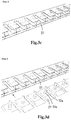
- each carrier 10 comprises an outer first side wall 11, an intermediate second side wall 12 and an outer third side wall 13 which extend parallel to each other in a horizontal direction.
- Partition walls 14 extend in a vertical direction in between the side walls 11, 12, 13.
- a bottom wall 15 is provided which extends in a vertical direction.
- the partition walls 14 and the bottom wall 15 delimit a first and second row of rectangular pocket-like insertion spaces 17a, 17b.
- Each insertion space 17a, 17b has an insertion opening 18a, 18b opposite the bottom wall 15.
- the first and second side walls 11, 12 are provided with primary and secondary slits 20, 21, which here are formed as U-shaped cut-outs.
- the slits 20, 21 open out towards the insertion openings 18 and extend in a so-called insertion direction X towards the bottom wall 15.
- An inlet station 24 is positioned at a right side of the apparatus 1.
- An outlet station 25 is positioned at a left side of the apparatus 1.
- the conveyor 4 gets driven to transport the carriers 10 at a substantially constant speed through the respective chambers 3 from the inlet station 24 towards the outlet station 25.
- the carriers 10 can temporarily be held at a stand still such that flexible food packages 27 can be placed in or taken out of the insertion spaces 17.
- the conveyor 4 has the freedom to form bigger or smaller free hanging loops 4a, 4b in front of the stations 24, 25.
- the inlet station 24 is provided with a conveyor belt 30a for moving the flexible food packages 27 towards the first row of insertion spaces 17a of a carrier 10 which has been stopped in front of it, and a conveyor belt 30b for at a same time moving the flexible food packages 27 towards the second row of insertion spaces 17b of another carrier 10 which has been stopped in front of it.
- first operating members 31a, 31b are provided at the ends of the belts 30a, 30b.
- Each operating member 31 comprises two vacuum bars 32 forming portions of a load bearing organ or element at the end of which suction heads 33 are provided.
- the assemblies of the vacuum bars 32 and suction heads 33 can be moved back and forth in the insertion direction X, which here is horizontally directed, into and out of the insertion spaces 17.
- For this operable translation means 34 are provided.
- the suction heads 33 are able to pick up the flexible food packages 27 from the respective belts 30 and then carry them freely floating into the respective rows of insertion spaces 17.
- the vacuum bars 32 get to project through the slits 20, 21 of the carrier 10 that gets loaded.
- the vacuum bars 32b are dimensioned prolonged relative to the vacuum bars 32a. This makes it possible for the vacuum bars 32b to project not only through the slits 20 in the upper first side wall 11, but also through the slits 21 in the intermediate second side wall 12, during placing of packages 27 into the second row of insertion spaces 17b.
- the vacuum bars 32a only need to project through the slits 20 in the upper first side wall 11 during placing of packages 27 into the first row of insertion spaces 17a, and therefore can be dimensioned shorter.
- a respective carrier 10 first gets stopped in front of the belt 30b and operating members 31b.
- Packages 27 can then be carefully picked up and placed in the second insertion spaces 17b ( fig. 3a-c ). Subsequently the respective carrier 10 can get transported towards and stopped in front of the belt 30a and operating members 31a. Packages 27 can then be carefully picked up and placed in the first insertion spaces 17a ( fig. 3d-f ).
- an efficient two-step loading method is possible.
- the thermally processed packages 27 in a similar manner can be unloaded from the carriers 10 again at the outlet station 25.
- the carriers 10 Owing to the fixed connection of the carriers 10 to the conveyor 4, the carriers 10 get stopped in front of the outlet station 25 turned upside down, that is to say with their slits 20, 21 at lower sides of the carriers 10. Therefore, at the outlet station 25 a double set of second operating members 36 is provided which have their vacuum bars and suction heads project upwards (instead of downwards as is the case at the inlet station 24). In this way they are able to connect to the packages 27 lying in the carriers 10 and then carefully move them out of there and place them on top of conveyor belts 37.
- the unloading here is performed as an efficient two-step unloading method in which first the packages are taken out of the first row of insertion spaces and subsequently out of the second row of insertion spaces.
- the carriers 10 actively co-rotate together with the chain links when passing by the U-turn sections 5, 6. See also fig. 4a-b .
- the packages 27 placed inside the carriers 10 advantageously get mildly agitated during the sterilization.
- Fig. 5a shows a variant of such a rotatable connection in which the carriers 10 have the full freedom to maintain a certain positioning, in this case a horizontal positioning, relative to the horizontal during their passing of the U-turn section 5.
- Fig. 5b shows a variant of such a rotatable connection in which the carriers 10 can be actively given an aimed rotational movement.
- Rotational movement then can be obtained by means of a driven rotation chain.
- Each carrier 10 then can be provided with a chain wheel which grips into this rotation chain.
- the swinging movements can be seen in the number of differing positions which are shown for the respective carriers 10 when passing the U-turn section 5.
- the packages 27 placed inside the carriers 10 advantageously can get actively rotated and thus can get agitated during the sterilization.
- each of the carriers can be provided with a closable hatch 40.
- This hatch 40 can be hingedly connected to the carrier 10 and can be automatically opened and closed before and after the stations 24, 25.
- the hatches 40 may help to prevent the packages 27 from starting to float out of the carriers 10 when transported through those tower sections 2 that are filled with fluid columns. Also these hatches 40 make it possible for the carriers 10 to get actively rotated even such that the insertion openings 18a, 18b may temporarily get directed downwards. This is shown in fig. 5b .
- Fig. 6 shows a variant in which only one heating and/or cooling chamber 60 is provided.
- An endless conveyor 61 runs with horizontally and vertically orientated tracks 61a respectively 61b through the chamber 60 and is guided over a plurality of guiding wheels 62.
- inlet and outlet stations 63, 64 are provided outside the chamber 60.
- the inlet and outlet stations 63, 64 are positioned at a same side of the chamber 60.
- inventive carriers which are provided with slits such that load bearing organs; for example, vacuum bars 32a, 32b, are able to freely move back and forth there through during loading and/or unloading of the carriers at the inlet and outlet stations 63, 64.
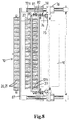
- a first operating member 70 is designed such that it can pick up two sets of flexible food packages 27 lying behind each other at a same time from a conveyor belt 30 ( fig. 7a ). Subsequently the operating member 70 can be operated to place the first set of packages 27 inside a first upper row of insertion spaces 17a' from a carrier 10', whereas the second set of packages 27 at the same time gets placed inside a second lower row of insertion spaces 17b" of a following carrier 10" ( fig. 7b ) that lies underneath the carrier 10'.
- the conveyor 4 (only part of which is shown) to which the carriers 10 are connected, is controlled to make an indexed movement and moves the carriers 10, that are positioned in front of the inlet station, one pitch forward.
- the operating member 70 then gets operated to pick up two new sets of flexible food packages 27 from the conveyor belt 30, after which it places the first set inside a first row of insertion spaces 17a" from the carrier 10", whereas the second set at the same time gets placed inside a second row of insertion spaces 17b'" of a next carrier 10"'.
- a two-step loading method is possible while only one conveyor belt 30 is necessary. This reduces cost and saves space.
- the operating member 70 comprises a piston-cylinder operated multiple-rod mechanism 71 (four-bar linkage mechanism) with two sets of load bearing organs and holding means or assembly 72a, 72b, that can be operated between a picking position ( fig. 7a ) in which the two sets lie behind each other, towards a placing position ( fig. 7b ) in which the two sets lie above each other.
- a picking position fig. 7a
- a placing position fig. 7b
- the multiple-rod mechanism 71 comprises a main or control rod or link 74 that can be moved up and down by an operable first piston-cylinder 75, and back and forth in the insertion direction X by an operable second piston-cylinder 76.
- a counterweight 78 is provided that moves counter to the second piston-cylinder 76 during its back and forth movements in the insertion direction X.
- An auxiliary or slave rod or link 80 is hingedly connected by means of two transverse rods 81, 82 to the main rod 74.
- the front set of load bearing organs with holding means 72a is connected to a lower end of the auxiliary rod 80.
- the back set of load bearing organs with holding means 72b is connected to a lower end of the main rod 74.
- One of the four hinge connections between the rods 74, 80, 81, 82 comprises a drive unit 84 for being able to controllably rotate the transverse rods 81, 82 towards other angular positions relative to the main and auxiliary rod 74, 80. Because of this, the auxiliary rod 80 moves together with its front set of load bearing organs with holding means from its picking position ( Fig. 7a ) towards its placing position ( Fig. 7b ). The operating member 70 together with its multiple-rod mechanism 71 thus is able to perform rotational and translational movements with the packages its picks up in such a way that any accelerations on the packages 27 are kept balanced with holding forces of its holding means onto the packages 27.
- the load bearing organs with holding means 72 here comprise vacuum bars with suction heads.
- the holding means When operated, the holding means are well able to pick up the flexible food packages 27 from the belt 30 and then carry them freely floating into the respective rows of insertion spaces 17 of carrier 10. During this movement, the vacuum bars 32 engage through slits 20, 21 of the carrier 10 being loaded.
- each load bearing organ with holding means 72 is connected to a horizontally projecting stave that is designed such slender that, if a lower insertion space 17b needs to be loaded with a package 27, the stave is freely movable into and out of the then still empty insertion space 17a while having the load bearing organ extend through the slit 21 in the intermediate side wall between the insertion spaces 17a, 17b.
- the two sets of load bearing organs with holding means can be dimensioned the same, because the load bearing organs of both sets 72a, 72b can be made with equal lengths. Both sets of load bearing organs thus are able to either load a package 27 into an upper insertions pace 17a or into a lower insertion space 17b, depending on the stage of the loading and positioning of the carriers 10 in front of them.
- the inlet station includes two guiding plates 87 that are positioned directly in front of the aimed stopping positions of the carriers 10. Those guiding plates 87 serve the purpose of preventing a package 27 from becoming stuck behind projecting parts of the carriers 10, for example, hatches 40 that have gotten hinged downwards into their open positions at the location of the inlet station.
- a variant is shown for the outlet station, in which similar parts have been given the same reference numerals as in the previous drawings.
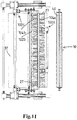
- two operating members 100 together are designed such that a second operating member 100a can pick up two sets of flexible food packages 27 lying inside respective insertion spaces of carriers 10 ( fig. 10a ), and then have them taken over by a third operating member 100b which places them behind each other onto a conveyor belt 37 ( fig. 10b ).
- the second operating member 100a largely resembles the first operating member 70 at the inlet station, that is to say that it comprises a multiple-rod mechanism that can be operated to pick a first set of packages 27 out of a row of insertion spaces 17' from a carrier 10', whereas a second set of packages 27 at the same time gets picked out of a row of insertion spaces 17" of a following carrier 10" that lies underneath the carrier 10'.
- the carriers 10 are positioned upside down with the slits 20, 21 at lower sides of the insertion spaces 17.
- the second operating member 100a comprises a piston-cylinder operated multiple-rod mechanism (four-bar linkage mechanism) 101 with two sets of load bearing organs and holding means 102a, 102b, that can be operated to perform a combined translational and rotational movement between a picking position ( fig. 10a ) in which the two sets lie above each other, towards a placing position ( fig. 10b ) in which the two sets lie behind each other.
- the holding means of the second operating member 100a here are provided on top of the load bearing organs.
- the third operating member 100b also comprises two sets of load bearing organs with holding means 104a, 104b.
- the holding means of this third operating member 100b are provided below its load bearing organs.
- the third operating member 100b comprises an operable piston-cylinder 105 for having the sets 104a, 104b perform up and down movements towards and away from the conveyor 37.
- the second operating member 100a after having picked up the packages 27 is able to move them to a position directly underneath the sets of the load bearing organs and holding means 104a, 104b of the third operating member 100b. Suitable operation of the holding means of the respective sets 102, 104 then can cause the packages 27 to be taken over by the third operating member 100b from the second operating member 100a ( fig. 10b ). Subsequently the second operating member 100a can be controlled to move out of the way towards its picking position as shown in fig. 10a for picking out new sets of packages 27 out of the carriers 10, while the third operating member 100b gets controlled to place its sets of packages 27 on top of the conveyor 37 as also is shown in fig. 10a .
- a two-step unloading method is possible while only one conveyor belt 37 is necessary, again reducing cost and saving space.
- the shapes and dimensions of the carriers, slits and the like can be varied.
- the carriers instead of being used for sterilization purposes it is also possible to use the carriers for other types of thermal processing, like pasteurization.
- the conveyor driven intermittently it is also possible to provide each of the insertion spaces with two or more slits such that it also gets possible to load and unload larger dimensioned flexible packages therein by means of a corresponding number of adjacent operating members.
- the operating members can operate by other than a vacuum system, including, for example, mechanically grasping the packages 27.
- the invention provides an advantageous carrier design which in particular can be used in an efficient manner for sterilization of vulnerable flexible packages in a hydrostatic continuous steriliser. High capacities of more than 1000 packages/minute have appeared possible with this.
Landscapes
- Engineering & Computer Science (AREA)
- Life Sciences & Earth Sciences (AREA)
- Wood Science & Technology (AREA)
- Zoology (AREA)
- Chemical & Material Sciences (AREA)
- Food Science & Technology (AREA)
- Polymers & Plastics (AREA)
- Mechanical Engineering (AREA)
- Food Preservation Except Freezing, Refrigeration, And Drying (AREA)
- Supplying Of Containers To The Packaging Station (AREA)
Claims (15)
- Vorrichtung zur thermischen Behandlung von Lebensmittelprodukten in versiegelten Verpackungen, insbesondere flexiblen Verpackungen, umfassend:- eine oder mehrere Heiz- und/oder Kühlkammern (3);- einen endlosen Förderer (4), der durch die Kammern (3) geführt wird;- eine Vielzahl von Produktträgern (10), die beabstandet mit dem Förderer (4) verbunden sind, wobei jeder Träger (10) mindestens eine erste Reihe von Einsetzräumen (17a) für anzuordnende Verpackungen (27) umfasst, wobei die Einsetzräume (17a) jeweils eine Einsetzöffnung (18a) aufweisen und die erste Reihe von Einsetzräumen (17a) mindestens teilweise durch eine erste Seitenwand (11) und eine gegenüberliegende zweite Seitenwand (12) begrenzt ist; und- eine Einlassstation (24), die ein oder mehrere erste Betätigungselemente (31a) aufweist, die betätigbar sind, um sich in die und aus den Einsetzräumen (17a) zu bewegen, um Packungen (27) in einer Einsetzrichtung (X) in die Einsetzräume (17a) zu bewegen;
wobei der Förderer (4) zum Transportieren der Träger (10) mit in deren Einsetzräumen (17a) angeordneten Packungen (27) durch die eine oder mehrere Heiz- und/oder Kühlkammern (3) ausgelegt ist,
dadurch gekennzeichnet, dass
die erste Seitenwand (11) mindestens einen primären Schlitz (20) für jeden Einsetzraum (17a) aufweist, wobei sich der primäre Schlitz (20) im Wesentlichen in der Einsetzrichtung (X) erstreckt, und wobei sich der primäre Schlitz (20) zur Einsetzöffnung (18a) des entsprechenden Einsetzraums (17a) hin öffnet,
wobei die ersten Betätigungselemente (31a) Last tragende Organe (32a) umfassen, die zum Aufnehmen und Tragen von Packungen (27) betätigbar sind, wobei sich die Last tragenden Organe (32a) im Wesentlichen in einer Querrichtung relativ zu den Seitenwänden (11, 12) erstrecken, und wobei die Last tragenden Organe (32a) in der Einsetzrichtung (X) bewegbar sind, während sie durch die primären Schlitze (20) während des Anordnens von Packungen (27) in die erste Reihe von Einsetzräumen (17a) vorstehen. - Vorrichtung nach Anspruch 1, wobei jeder Träger (10) ferner eine zweite Reihe von Einsetzräumen (17b) für anzuordnende Verpackungen (27) aufweist, wobei die zweite Reihe von Einsetzräumen (17b) zumindest teilweise durch die zweite Seitenwand (12) und eine gegenüberliegende dritte Seitenwand (13) begrenzt ist,
wobei die zweite Seitenwand (12) mindestens einen sekundären Schlitz (21) für jeden Einsetzraum (17b) der zweiten Reihe von Einsetzräumen (17b) aufweist, wobei sich der sekundäre Schlitz (21) im Wesentlichen in der Einsetzrichtung (X) erstreckt und wobei sich der sekundäre Schlitz (21) zur Einsetzöffnung (18b) des entsprechenden Einsetzraums (17b) hin öffnet. - Vorrichtung nach Anspruch 2, wobei die Last tragenden Organe (32b) in der Einsetzrichtung (X) bewegbar sind, während sie sowohl durch den primären als auch durch den sekundären Schlitz (20, 21) während des Anordnens von Verpackungen (27) in die zweite Reihe von Einsetzräumen (17b) vorstehen.
- Vorrichtung nach Anspruch 2, wobei das tragende Organ (32b) mit einem Träger verbunden ist, der frei beweglich in den und aus dem Einsetzraum (17a) der ersten Reihe passt, während sich das tragende Organ (32b) durch den sekundären Schlitz (21) erstreckt.
- Vorrichtung nach einem der vorstehenden Ansprüche, wobei eine Auslassstation (25) vorgesehen ist, die ein oder mehrere zweite Betätigungselemente (36) umfasst, die betätigbar sind, um sich in die und aus den Einsetzräumen (17a, 17b) zu bewegen, um Packungen (27) in der Einsetzrichtung (X) aus den Einsetzräumen (17a, 17b) zu bewegen,
wobei die zweiten Betätigungselemente (36) Last tragende Organe umfassen, die zum Aufnehmen und Tragen von Packungen (27) betätigbar sind, wobei sich die Last tragenden Organe im Wesentlichen in einer Querrichtung relativ zu den Seitenwänden (11, 12, 13) erstrecken, und wobei die Last tragenden Organe in der Einsetzrichtung (X) bewegbar sind, während sie durch die primären Schlitze (20) während des Aufnehmens von Packungen (27) aus der ersten Reihe von Einsetzräumen (17a) vorstehen. - Vorrichtung nach einem der vorstehenden Ansprüche, wobei die Heiz- und/oder Kühlkammern (3) vertikal ausgerichtete Turmabschnitte (2) umfassen, durch die sich der Förderer (4) erstreckt.
- Vorrichtung nach einem der vorstehenden Ansprüche, wobei die Heiz- und/oder Kühlkammern (3) horizontal ausgerichtete Bahnabschnitte (61a) umfassen, durch die sich der Förderer (4) erstreckt.
- Vorrichtung nach einem der vorstehenden Ansprüche, wobei die Träger (10) verschließbare Luken (40) zum Verschließen der Einsetzöffnungen (17a, 17b) zwischen der Einlass- und der Auslassstation (24, 25) umfassen.
- Vorrichtung nach einem der vorstehenden Ansprüche 1-8, wobei die Träger (10) nicht drehbar mit dem Förderer (4) verbunden sind.
- Vorrichtung nach einem der vorstehenden Ansprüche 1-8, wobei die Träger (10) drehbar mit dem Förderer (4) verbunden sind.
- Vorrichtung nach einem der vorstehenden Ansprüche, wobei das Betätigungselement (70) mindestens zwei Sätze von Last tragenden Organen (72a, 72b) zum gleichzeitigen Aufnehmen und Tragen von mindestens zwei Sätzen der Packungen (27) in die oder aus den Trägern (10) umfasst.
- Vorrichtung nach Anspruch 11, wobei das Betätigungselement (70) einen Mehrstangenmechanismus (71) mit einer Hauptstange (74) und einer Hilfsstange (80) umfasst, wobei die Hilfsstange (80) durch Querstangen (81, 82) gelenkig mit der Hauptstange (74) verbunden ist, wobei ein Satz tragender Organe (72b) mit der Hauptstange (74) verbunden ist, und wobei ein weiterer Satz tragender Organe (72a) mit der Hilfsstange (80) verbunden ist.
- Vorrichtung nach einem der vorstehenden Ansprüche, wobei die Betätigungselemente (31a, 31b) durch ein Vakuumsystem betätigbar sind und wobei die Last tragenden Organe Saugköpfe (33) aufweisen.
- Träger zum Tragen von Lebensmittelprodukten in versiegelten Verpackungen durch die Vorrichtung nach einem der vorstehenden Ansprüche,
wobei der Träger (10) mindestens die erste Reihe von Einsetzräumen (17a) für Packungen (27) umfasst, die darin in der Einsetzrichtung (X) durch das Betätigungselement (31a) anzuordnen sind, wobei die Einsetzräume (17a) jeweils ihre in den Einsetzraum (17a) führende Einsetzöffnung (18a) aufweisen und die erste Reihe von Einsetzräumen (17a) mindestens teilweise durch die erste Seitenwand (11) und die gegenüberliegende zweite Seitenwand (12) begrenzt ist,
wobei jeder Einsetzraum (17a, 17b) ferner durch zwei gegenüberliegende Trennwände (14) begrenzt ist, die mit den Seitenwänden (11, 12) verbunden sind, und
wobei die erste Seitenwand (11) die primären Schlitze (20) für jeden der Einsetzräume (17a) umfasst, wobei sich die primären Schlitze (20) im Wesentlichen in der Einsetzrichtung (X) erstrecken, und wobei sich die primären Schlitze (20) zur Einsetzöffnung (18a) ihres jeweiligen Einsetzraums (17a) hin öffnen, um das Betätigungselement (31a) während des Einsetzens und Entfernens der Packungen (27) aufzunehmen. - Verfahren zum Betätigen der Vorrichtung nach einem der Ansprüche 1-13, umfassend die folgenden Schritte- Abholen von versiegelten Lebensmittelverpackungen (27) mit den ersten Bedienungselementen (31a);- Bewegen der Packungen (27) mit Hilfe der ersten Bedienungselemente (31a) in die Einsetzräume (17a) der Träger (10), während sich die tragenden Organe (32a) durch die primären Schlitze (20) bewegen;- Transportieren der Träger (10) durch die Heiz- und/oder Kühlkammern (3), während die Packungen (27) thermisch bearbeitet werden;- Entladen der thermisch behandelten Packungen (27) aus den Trägern (10).
Applications Claiming Priority (2)
| Application Number | Priority Date | Filing Date | Title |
|---|---|---|---|
| NL2012876A NL2012876B1 (en) | 2014-05-23 | 2014-05-23 | Apparatus for thermally processing food packages comprising product carriers with positive package handling. |
| PCT/NL2015/050364 WO2015178772A1 (en) | 2014-05-23 | 2015-05-20 | Apparatus for thermally processing food packages comprising product carriers with positive package handling |
Publications (2)
| Publication Number | Publication Date |
|---|---|
| EP3145326A1 EP3145326A1 (de) | 2017-03-29 |
| EP3145326B1 true EP3145326B1 (de) | 2020-07-15 |
Family
ID=51136733
Family Applications (1)
| Application Number | Title | Priority Date | Filing Date |
|---|---|---|---|
| EP15732468.2A Active EP3145326B1 (de) | 2014-05-23 | 2015-05-20 | Vorrichtung zur thermischen behandlung von lebensmittelverpackungen mit produktträgern mit positiver verpackungshandhabung |
Country Status (5)
| Country | Link |
|---|---|
| US (1) | US10980256B2 (de) |
| EP (1) | EP3145326B1 (de) |
| CN (1) | CN107072260A (de) |
| NL (1) | NL2012876B1 (de) |
| WO (1) | WO2015178772A1 (de) |
Families Citing this family (1)
| Publication number | Priority date | Publication date | Assignee | Title |
|---|---|---|---|---|
| KR20230039834A (ko) * | 2021-09-13 | 2023-03-22 | 삼성디스플레이 주식회사 | 쉴딩백 그리핑 장치, 이를 포함하는 디스플레이 포장 시스템, 및 이들을 이용한 디스플레이 포장 방법 |
Family Cites Families (10)
| Publication number | Priority date | Publication date | Assignee | Title |
|---|---|---|---|---|
| US3774778A (en) * | 1971-06-09 | 1973-11-27 | R Flaig | Case packing machine |
| HU178860B (en) * | 1980-04-29 | 1982-07-28 | Agrober Mezoegazdasagi Elelm | Conveyor for can sterilizer |
| JPS62111825A (ja) * | 1985-11-06 | 1987-05-22 | Fuji Kikai Seizo Kk | キヤリヤテ−プから電子部品を取り出す方法 |
| NL8603157A (nl) * | 1986-12-11 | 1988-07-01 | Baxter Travenol Lab | Continu-sterilisator alsmede drager uit deze sterilisator. |
| US5488815A (en) * | 1994-06-10 | 1996-02-06 | Johnson & Johnson Vision Products, Inc. | Apparatus and method for sterilization and secondary packaging |
| DE19730901C2 (de) * | 1997-07-18 | 1999-05-06 | Fresenius Ag | Verfahren zum Sterilisieren von in flexiblen Folienverpackungen befindlichem Sterilisiergut und Vorrichtung zur Durchführung des Verfahrens |
| US7089717B2 (en) * | 2003-05-05 | 2006-08-15 | Langen Packaging Inc. | Tray loader |
| SE529732C2 (sv) * | 2006-03-21 | 2007-11-06 | Tetra Laval Holdings & Finance | Sätt att förpacka och i hållbarhetsförlängande syfte värmebehandla ett livsmedel |
| NL2002441C2 (nl) * | 2009-01-22 | 2010-07-26 | Stork Pmt | Transportsysteem. |
| CN102673823B (zh) * | 2011-03-17 | 2014-10-15 | 莫迪维克贸易有限公司 | 用于产品的包装和高压处理的包装机和方法 |
-
2014
- 2014-05-23 NL NL2012876A patent/NL2012876B1/en active
-
2015
- 2015-05-20 CN CN201580039606.9A patent/CN107072260A/zh active Pending
- 2015-05-20 WO PCT/NL2015/050364 patent/WO2015178772A1/en not_active Ceased
- 2015-05-20 US US15/313,491 patent/US10980256B2/en active Active
- 2015-05-20 EP EP15732468.2A patent/EP3145326B1/de active Active
Non-Patent Citations (1)
| Title |
|---|
| None * |
Also Published As
| Publication number | Publication date |
|---|---|
| US10980256B2 (en) | 2021-04-20 |
| US20170143015A1 (en) | 2017-05-25 |
| WO2015178772A1 (en) | 2015-11-26 |
| NL2012876B1 (en) | 2016-03-15 |
| EP3145326A1 (de) | 2017-03-29 |
| CN107072260A (zh) | 2017-08-18 |
Similar Documents
| Publication | Publication Date | Title |
|---|---|---|
| EP0562156B1 (de) | Einrichtung zur Beförderung von kleinen Gegenständen durch Behandlungsräume | |
| CN103857969B (zh) | 具有装载和卸载装置的冷冻干燥设备 | |
| US4378873A (en) | Continuous linear chain conveyor system operating throughout multiple tiers with dual spaced chains moving directly attached multiple adjacent trays which level to support the conveyed product | |
| CN104661515A (zh) | 用于产品和/或包装的存储和/或分配的系统 | |
| CA2682399C (en) | Tray-based continuous throughput blast freezer | |
| EP2368405A1 (de) | Vorrichtung und verfahren zur massensterilisierung und | |
| CA2812911C (en) | Recirculating continuous storage apparatus | |
| US8505446B2 (en) | Plant for drying and ripening food products and method for transferring such products within said plant | |
| KR100477871B1 (ko) | 연질포장제품을 연속적으로 살균하고자하는 연속살균장치 | |
| US10980256B2 (en) | Apparatus for thermally processing food packages comprising product carriers with positive package handling | |
| US7846486B2 (en) | Pasteurization or sterilization method and device for carrying out same | |
| JP5660286B2 (ja) | 物品洗浄システム | |
| CN112810935B (zh) | 开袋装置、食品加工系统以及食品加工方法 | |
| JP2024077264A (ja) | 容器充填シール装置 | |
| US5199346A (en) | Apparatus for high speed sterilization of irregularly shaped containers | |
| TWI786935B (zh) | 加熱殺菌冷卻機 | |
| EP3801075A1 (de) | Entladevorrichtung für stabförmige artikel der tabakindustrie | |
| JP3682440B2 (ja) | 加熱殺菌・滅菌機におけるトレーの支持装置 | |
| HK40051893A (en) | Bag opening device, food processing system and a food processing method | |
| HK40051893B (en) | Bag opening device, food processing system and a food processing method | |
| AU2024308727A1 (en) | A forced-air cooling/heating facility and associated cooling/heating method | |
| NZ608552B2 (en) | Recirculating continuous storage apparatus | |
| NL8202255A (nl) | Hogedruk rechthoekige tunnelsterilisator. |
Legal Events
| Date | Code | Title | Description |
|---|---|---|---|
| STAA | Information on the status of an ep patent application or granted ep patent |
Free format text: STATUS: THE INTERNATIONAL PUBLICATION HAS BEEN MADE |
|
| PUAI | Public reference made under article 153(3) epc to a published international application that has entered the european phase |
Free format text: ORIGINAL CODE: 0009012 |
|
| STAA | Information on the status of an ep patent application or granted ep patent |
Free format text: STATUS: REQUEST FOR EXAMINATION WAS MADE |
|
| 17P | Request for examination filed |
Effective date: 20161219 |
|
| AK | Designated contracting states |
Kind code of ref document: A1 Designated state(s): AL AT BE BG CH CY CZ DE DK EE ES FI FR GB GR HR HU IE IS IT LI LT LU LV MC MK MT NL NO PL PT RO RS SE SI SK SM TR |
|
| AX | Request for extension of the european patent |
Extension state: BA ME |
|
| DAV | Request for validation of the european patent (deleted) | ||
| DAX | Request for extension of the european patent (deleted) | ||
| STAA | Information on the status of an ep patent application or granted ep patent |
Free format text: STATUS: EXAMINATION IS IN PROGRESS |
|
| 17Q | First examination report despatched |
Effective date: 20180606 |
|
| RAP1 | Party data changed (applicant data changed or rights of an application transferred) |
Owner name: JBT FOOD & DAIRY SYSTEMS B.V. |
|
| GRAP | Despatch of communication of intention to grant a patent |
Free format text: ORIGINAL CODE: EPIDOSNIGR1 |
|
| STAA | Information on the status of an ep patent application or granted ep patent |
Free format text: STATUS: GRANT OF PATENT IS INTENDED |
|
| RIC1 | Information provided on ipc code assigned before grant |
Ipc: B65B 55/00 20060101ALI20190108BHEP Ipc: A23L 3/04 20060101AFI20190108BHEP |
|
| INTG | Intention to grant announced |
Effective date: 20190208 |
|
| GRAJ | Information related to disapproval of communication of intention to grant by the applicant or resumption of examination proceedings by the epo deleted |
Free format text: ORIGINAL CODE: EPIDOSDIGR1 |
|
| STAA | Information on the status of an ep patent application or granted ep patent |
Free format text: STATUS: EXAMINATION IS IN PROGRESS |
|
| INTC | Intention to grant announced (deleted) | ||
| GRAP | Despatch of communication of intention to grant a patent |
Free format text: ORIGINAL CODE: EPIDOSNIGR1 |
|
| STAA | Information on the status of an ep patent application or granted ep patent |
Free format text: STATUS: GRANT OF PATENT IS INTENDED |
|
| RIC1 | Information provided on ipc code assigned before grant |
Ipc: A23L 3/02 20060101ALI20200116BHEP Ipc: A23L 3/04 20060101AFI20200116BHEP Ipc: B65B 55/00 20060101ALI20200116BHEP |
|
| INTG | Intention to grant announced |
Effective date: 20200207 |
|
| GRAS | Grant fee paid |
Free format text: ORIGINAL CODE: EPIDOSNIGR3 |
|
| GRAA | (expected) grant |
Free format text: ORIGINAL CODE: 0009210 |
|
| STAA | Information on the status of an ep patent application or granted ep patent |
Free format text: STATUS: THE PATENT HAS BEEN GRANTED |
|
| AK | Designated contracting states |
Kind code of ref document: B1 Designated state(s): AL AT BE BG CH CY CZ DE DK EE ES FI FR GB GR HR HU IE IS IT LI LT LU LV MC MK MT NL NO PL PT RO RS SE SI SK SM TR |
|
| REG | Reference to a national code |
Ref country code: CH Ref legal event code: EP Ref country code: GB Ref legal event code: FG4D |
|
| REG | Reference to a national code |
Ref country code: DE Ref legal event code: R096 Ref document number: 602015055753 Country of ref document: DE |
|
| REG | Reference to a national code |
Ref country code: IE Ref legal event code: FG4D |
|
| REG | Reference to a national code |
Ref country code: AT Ref legal event code: REF Ref document number: 1289962 Country of ref document: AT Kind code of ref document: T Effective date: 20200815 |
|
| REG | Reference to a national code |
Ref country code: LT Ref legal event code: MG4D |
|
| REG | Reference to a national code |
Ref country code: AT Ref legal event code: MK05 Ref document number: 1289962 Country of ref document: AT Kind code of ref document: T Effective date: 20200715 |
|
| REG | Reference to a national code |
Ref country code: NL Ref legal event code: MP Effective date: 20200715 |
|
| PG25 | Lapsed in a contracting state [announced via postgrant information from national office to epo] |
Ref country code: NO Free format text: LAPSE BECAUSE OF FAILURE TO SUBMIT A TRANSLATION OF THE DESCRIPTION OR TO PAY THE FEE WITHIN THE PRESCRIBED TIME-LIMIT Effective date: 20201015 Ref country code: BG Free format text: LAPSE BECAUSE OF FAILURE TO SUBMIT A TRANSLATION OF THE DESCRIPTION OR TO PAY THE FEE WITHIN THE PRESCRIBED TIME-LIMIT Effective date: 20201015 Ref country code: AT Free format text: LAPSE BECAUSE OF FAILURE TO SUBMIT A TRANSLATION OF THE DESCRIPTION OR TO PAY THE FEE WITHIN THE PRESCRIBED TIME-LIMIT Effective date: 20200715 Ref country code: SE Free format text: LAPSE BECAUSE OF FAILURE TO SUBMIT A TRANSLATION OF THE DESCRIPTION OR TO PAY THE FEE WITHIN THE PRESCRIBED TIME-LIMIT Effective date: 20200715 Ref country code: HR Free format text: LAPSE BECAUSE OF FAILURE TO SUBMIT A TRANSLATION OF THE DESCRIPTION OR TO PAY THE FEE WITHIN THE PRESCRIBED TIME-LIMIT Effective date: 20200715 Ref country code: LT Free format text: LAPSE BECAUSE OF FAILURE TO SUBMIT A TRANSLATION OF THE DESCRIPTION OR TO PAY THE FEE WITHIN THE PRESCRIBED TIME-LIMIT Effective date: 20200715 Ref country code: PT Free format text: LAPSE BECAUSE OF FAILURE TO SUBMIT A TRANSLATION OF THE DESCRIPTION OR TO PAY THE FEE WITHIN THE PRESCRIBED TIME-LIMIT Effective date: 20201116 Ref country code: ES Free format text: LAPSE BECAUSE OF FAILURE TO SUBMIT A TRANSLATION OF THE DESCRIPTION OR TO PAY THE FEE WITHIN THE PRESCRIBED TIME-LIMIT Effective date: 20200715 Ref country code: FI Free format text: LAPSE BECAUSE OF FAILURE TO SUBMIT A TRANSLATION OF THE DESCRIPTION OR TO PAY THE FEE WITHIN THE PRESCRIBED TIME-LIMIT Effective date: 20200715 Ref country code: GR Free format text: LAPSE BECAUSE OF FAILURE TO SUBMIT A TRANSLATION OF THE DESCRIPTION OR TO PAY THE FEE WITHIN THE PRESCRIBED TIME-LIMIT Effective date: 20201016 |
|
| PG25 | Lapsed in a contracting state [announced via postgrant information from national office to epo] |
Ref country code: LV Free format text: LAPSE BECAUSE OF FAILURE TO SUBMIT A TRANSLATION OF THE DESCRIPTION OR TO PAY THE FEE WITHIN THE PRESCRIBED TIME-LIMIT Effective date: 20200715 Ref country code: RS Free format text: LAPSE BECAUSE OF FAILURE TO SUBMIT A TRANSLATION OF THE DESCRIPTION OR TO PAY THE FEE WITHIN THE PRESCRIBED TIME-LIMIT Effective date: 20200715 Ref country code: PL Free format text: LAPSE BECAUSE OF FAILURE TO SUBMIT A TRANSLATION OF THE DESCRIPTION OR TO PAY THE FEE WITHIN THE PRESCRIBED TIME-LIMIT Effective date: 20200715 Ref country code: IS Free format text: LAPSE BECAUSE OF FAILURE TO SUBMIT A TRANSLATION OF THE DESCRIPTION OR TO PAY THE FEE WITHIN THE PRESCRIBED TIME-LIMIT Effective date: 20201115 |
|
| PG25 | Lapsed in a contracting state [announced via postgrant information from national office to epo] |
Ref country code: NL Free format text: LAPSE BECAUSE OF FAILURE TO SUBMIT A TRANSLATION OF THE DESCRIPTION OR TO PAY THE FEE WITHIN THE PRESCRIBED TIME-LIMIT Effective date: 20200715 |
|
| REG | Reference to a national code |
Ref country code: DE Ref legal event code: R097 Ref document number: 602015055753 Country of ref document: DE |
|
| PG25 | Lapsed in a contracting state [announced via postgrant information from national office to epo] |
Ref country code: IT Free format text: LAPSE BECAUSE OF FAILURE TO SUBMIT A TRANSLATION OF THE DESCRIPTION OR TO PAY THE FEE WITHIN THE PRESCRIBED TIME-LIMIT Effective date: 20200715 Ref country code: CZ Free format text: LAPSE BECAUSE OF FAILURE TO SUBMIT A TRANSLATION OF THE DESCRIPTION OR TO PAY THE FEE WITHIN THE PRESCRIBED TIME-LIMIT Effective date: 20200715 Ref country code: DK Free format text: LAPSE BECAUSE OF FAILURE TO SUBMIT A TRANSLATION OF THE DESCRIPTION OR TO PAY THE FEE WITHIN THE PRESCRIBED TIME-LIMIT Effective date: 20200715 Ref country code: EE Free format text: LAPSE BECAUSE OF FAILURE TO SUBMIT A TRANSLATION OF THE DESCRIPTION OR TO PAY THE FEE WITHIN THE PRESCRIBED TIME-LIMIT Effective date: 20200715 Ref country code: SM Free format text: LAPSE BECAUSE OF FAILURE TO SUBMIT A TRANSLATION OF THE DESCRIPTION OR TO PAY THE FEE WITHIN THE PRESCRIBED TIME-LIMIT Effective date: 20200715 Ref country code: RO Free format text: LAPSE BECAUSE OF FAILURE TO SUBMIT A TRANSLATION OF THE DESCRIPTION OR TO PAY THE FEE WITHIN THE PRESCRIBED TIME-LIMIT Effective date: 20200715 |
|
| PLBE | No opposition filed within time limit |
Free format text: ORIGINAL CODE: 0009261 |
|
| STAA | Information on the status of an ep patent application or granted ep patent |
Free format text: STATUS: NO OPPOSITION FILED WITHIN TIME LIMIT |
|
| PG25 | Lapsed in a contracting state [announced via postgrant information from national office to epo] |
Ref country code: AL Free format text: LAPSE BECAUSE OF FAILURE TO SUBMIT A TRANSLATION OF THE DESCRIPTION OR TO PAY THE FEE WITHIN THE PRESCRIBED TIME-LIMIT Effective date: 20200715 |
|
| 26N | No opposition filed |
Effective date: 20210416 |
|
| PG25 | Lapsed in a contracting state [announced via postgrant information from national office to epo] |
Ref country code: SK Free format text: LAPSE BECAUSE OF FAILURE TO SUBMIT A TRANSLATION OF THE DESCRIPTION OR TO PAY THE FEE WITHIN THE PRESCRIBED TIME-LIMIT Effective date: 20200715 |
|
| PG25 | Lapsed in a contracting state [announced via postgrant information from national office to epo] |
Ref country code: SI Free format text: LAPSE BECAUSE OF FAILURE TO SUBMIT A TRANSLATION OF THE DESCRIPTION OR TO PAY THE FEE WITHIN THE PRESCRIBED TIME-LIMIT Effective date: 20200715 |
|
| REG | Reference to a national code |
Ref country code: CH Ref legal event code: PL |
|
| GBPC | Gb: european patent ceased through non-payment of renewal fee |
Effective date: 20210520 |
|
| PG25 | Lapsed in a contracting state [announced via postgrant information from national office to epo] |
Ref country code: CH Free format text: LAPSE BECAUSE OF NON-PAYMENT OF DUE FEES Effective date: 20210531 Ref country code: LU Free format text: LAPSE BECAUSE OF NON-PAYMENT OF DUE FEES Effective date: 20210520 Ref country code: MC Free format text: LAPSE BECAUSE OF FAILURE TO SUBMIT A TRANSLATION OF THE DESCRIPTION OR TO PAY THE FEE WITHIN THE PRESCRIBED TIME-LIMIT Effective date: 20200715 Ref country code: LI Free format text: LAPSE BECAUSE OF NON-PAYMENT OF DUE FEES Effective date: 20210531 |
|
| REG | Reference to a national code |
Ref country code: BE Ref legal event code: MM Effective date: 20210531 |
|
| PG25 | Lapsed in a contracting state [announced via postgrant information from national office to epo] |
Ref country code: IE Free format text: LAPSE BECAUSE OF NON-PAYMENT OF DUE FEES Effective date: 20210520 Ref country code: GB Free format text: LAPSE BECAUSE OF NON-PAYMENT OF DUE FEES Effective date: 20210520 |
|
| PG25 | Lapsed in a contracting state [announced via postgrant information from national office to epo] |
Ref country code: BE Free format text: LAPSE BECAUSE OF NON-PAYMENT OF DUE FEES Effective date: 20210531 |
|
| REG | Reference to a national code |
Ref country code: FR Ref legal event code: PLFP Year of fee payment: 9 |
|
| PG25 | Lapsed in a contracting state [announced via postgrant information from national office to epo] |
Ref country code: HU Free format text: LAPSE BECAUSE OF FAILURE TO SUBMIT A TRANSLATION OF THE DESCRIPTION OR TO PAY THE FEE WITHIN THE PRESCRIBED TIME-LIMIT; INVALID AB INITIO Effective date: 20150520 |
|
| PG25 | Lapsed in a contracting state [announced via postgrant information from national office to epo] |
Ref country code: CY Free format text: LAPSE BECAUSE OF FAILURE TO SUBMIT A TRANSLATION OF THE DESCRIPTION OR TO PAY THE FEE WITHIN THE PRESCRIBED TIME-LIMIT Effective date: 20200715 |
|
| P01 | Opt-out of the competence of the unified patent court (upc) registered |
Effective date: 20230526 |
|
| PG25 | Lapsed in a contracting state [announced via postgrant information from national office to epo] |
Ref country code: MK Free format text: LAPSE BECAUSE OF FAILURE TO SUBMIT A TRANSLATION OF THE DESCRIPTION OR TO PAY THE FEE WITHIN THE PRESCRIBED TIME-LIMIT Effective date: 20200715 |
|
| PG25 | Lapsed in a contracting state [announced via postgrant information from national office to epo] |
Ref country code: TR Free format text: LAPSE BECAUSE OF FAILURE TO SUBMIT A TRANSLATION OF THE DESCRIPTION OR TO PAY THE FEE WITHIN THE PRESCRIBED TIME-LIMIT Effective date: 20200715 |
|
| PG25 | Lapsed in a contracting state [announced via postgrant information from national office to epo] |
Ref country code: MT Free format text: LAPSE BECAUSE OF FAILURE TO SUBMIT A TRANSLATION OF THE DESCRIPTION OR TO PAY THE FEE WITHIN THE PRESCRIBED TIME-LIMIT Effective date: 20200715 |
|
| REG | Reference to a national code |
Ref country code: DE Ref legal event code: R079 Ref document number: 602015055753 Country of ref document: DE Free format text: PREVIOUS MAIN CLASS: A23L0003040000 Ipc: A23B0002220000 |
|
| PGFP | Annual fee paid to national office [announced via postgrant information from national office to epo] |
Ref country code: DE Payment date: 20250325 Year of fee payment: 11 |
|
| PGFP | Annual fee paid to national office [announced via postgrant information from national office to epo] |
Ref country code: FR Payment date: 20260323 Year of fee payment: 12 |