EP3145569B1 - Verdampfer - Google Patents
Verdampfer Download PDFInfo
- Publication number
- EP3145569B1 EP3145569B1 EP15730698.6A EP15730698A EP3145569B1 EP 3145569 B1 EP3145569 B1 EP 3145569B1 EP 15730698 A EP15730698 A EP 15730698A EP 3145569 B1 EP3145569 B1 EP 3145569B1
- Authority
- EP
- European Patent Office
- Prior art keywords
- gas
- flow
- medium
- flow rate
- vaporizer
- Prior art date
- Legal status (The legal status is an assumption and is not a legal conclusion. Google has not performed a legal analysis and makes no representation as to the accuracy of the status listed.)
- Active
Links
Images


Classifications
-
- A—HUMAN NECESSITIES
- A61—MEDICAL OR VETERINARY SCIENCE; HYGIENE
- A61M—DEVICES FOR INTRODUCING MEDIA INTO, OR ONTO, THE BODY; DEVICES FOR TRANSDUCING BODY MEDIA OR FOR TAKING MEDIA FROM THE BODY; DEVICES FOR PRODUCING OR ENDING SLEEP OR STUPOR
- A61M16/00—Devices for influencing the respiratory system of patients by gas treatment, e.g. ventilators; Tracheal tubes
- A61M16/10—Preparation of respiratory gases or vapours
- A61M16/14—Preparation of respiratory gases or vapours by mixing different fluids, one of them being in a liquid phase
- A61M16/18—Vaporising devices for anaesthetic preparations
-
- A—HUMAN NECESSITIES
- A61—MEDICAL OR VETERINARY SCIENCE; HYGIENE
- A61M—DEVICES FOR INTRODUCING MEDIA INTO, OR ONTO, THE BODY; DEVICES FOR TRANSDUCING BODY MEDIA OR FOR TAKING MEDIA FROM THE BODY; DEVICES FOR PRODUCING OR ENDING SLEEP OR STUPOR
- A61M16/00—Devices for influencing the respiratory system of patients by gas treatment, e.g. ventilators; Tracheal tubes
- A61M16/10—Preparation of respiratory gases or vapours
- A61M16/1075—Preparation of respiratory gases or vapours by influencing the temperature
- A61M16/109—Preparation of respiratory gases or vapours by influencing the temperature the humidifying liquid or the beneficial agent
-
- A—HUMAN NECESSITIES
- A61—MEDICAL OR VETERINARY SCIENCE; HYGIENE
- A61M—DEVICES FOR INTRODUCING MEDIA INTO, OR ONTO, THE BODY; DEVICES FOR TRANSDUCING BODY MEDIA OR FOR TAKING MEDIA FROM THE BODY; DEVICES FOR PRODUCING OR ENDING SLEEP OR STUPOR
- A61M16/00—Devices for influencing the respiratory system of patients by gas treatment, e.g. ventilators; Tracheal tubes
- A61M16/10—Preparation of respiratory gases or vapours
- A61M16/14—Preparation of respiratory gases or vapours by mixing different fluids, one of them being in a liquid phase
- A61M16/147—Preparation of respiratory gases or vapours by mixing different fluids, one of them being in a liquid phase the respiratory gas not passing through the liquid container
-
- A—HUMAN NECESSITIES
- A61—MEDICAL OR VETERINARY SCIENCE; HYGIENE
- A61M—DEVICES FOR INTRODUCING MEDIA INTO, OR ONTO, THE BODY; DEVICES FOR TRANSDUCING BODY MEDIA OR FOR TAKING MEDIA FROM THE BODY; DEVICES FOR PRODUCING OR ENDING SLEEP OR STUPOR
- A61M16/00—Devices for influencing the respiratory system of patients by gas treatment, e.g. ventilators; Tracheal tubes
- A61M16/10—Preparation of respiratory gases or vapours
- A61M16/14—Preparation of respiratory gases or vapours by mixing different fluids, one of them being in a liquid phase
- A61M16/16—Devices to humidify the respiration air
- A61M16/161—Devices to humidify the respiration air with means for measuring the humidity
-
- A—HUMAN NECESSITIES
- A61—MEDICAL OR VETERINARY SCIENCE; HYGIENE
- A61M—DEVICES FOR INTRODUCING MEDIA INTO, OR ONTO, THE BODY; DEVICES FOR TRANSDUCING BODY MEDIA OR FOR TAKING MEDIA FROM THE BODY; DEVICES FOR PRODUCING OR ENDING SLEEP OR STUPOR
- A61M16/00—Devices for influencing the respiratory system of patients by gas treatment, e.g. ventilators; Tracheal tubes
- A61M16/10—Preparation of respiratory gases or vapours
- A61M16/14—Preparation of respiratory gases or vapours by mixing different fluids, one of them being in a liquid phase
- A61M16/18—Vaporising devices for anaesthetic preparations
- A61M16/183—Filling systems
-
- A—HUMAN NECESSITIES
- A61—MEDICAL OR VETERINARY SCIENCE; HYGIENE
- A61M—DEVICES FOR INTRODUCING MEDIA INTO, OR ONTO, THE BODY; DEVICES FOR TRANSDUCING BODY MEDIA OR FOR TAKING MEDIA FROM THE BODY; DEVICES FOR PRODUCING OR ENDING SLEEP OR STUPOR
- A61M16/00—Devices for influencing the respiratory system of patients by gas treatment, e.g. ventilators; Tracheal tubes
- A61M16/20—Valves specially adapted to medical respiratory devices
- A61M16/201—Controlled valves
-
- G—PHYSICS
- G01—MEASURING; TESTING
- G01F—MEASURING VOLUME, VOLUME FLOW, MASS FLOW OR LIQUID LEVEL; METERING BY VOLUME
- G01F1/00—Measuring the volume flow or mass flow of fluid or fluent solid material wherein the fluid passes through a meter in a continuous flow
- G01F1/68—Measuring the volume flow or mass flow of fluid or fluent solid material wherein the fluid passes through a meter in a continuous flow by using thermal effects
-
- G—PHYSICS
- G01—MEASURING; TESTING
- G01F—MEASURING VOLUME, VOLUME FLOW, MASS FLOW OR LIQUID LEVEL; METERING BY VOLUME
- G01F15/00—Details of, or accessories for, apparatus of groups G01F1/00 - G01F13/00 insofar as such details or appliances are not adapted to particular types of such apparatus
- G01F15/001—Means for regulating or setting the meter for a predetermined quantity
- G01F15/002—Means for regulating or setting the meter for a predetermined quantity for gases
-
- G—PHYSICS
- G01—MEASURING; TESTING
- G01F—MEASURING VOLUME, VOLUME FLOW, MASS FLOW OR LIQUID LEVEL; METERING BY VOLUME
- G01F15/00—Details of, or accessories for, apparatus of groups G01F1/00 - G01F13/00 insofar as such details or appliances are not adapted to particular types of such apparatus
- G01F15/005—Valves
-
- G—PHYSICS
- G01—MEASURING; TESTING
- G01F—MEASURING VOLUME, VOLUME FLOW, MASS FLOW OR LIQUID LEVEL; METERING BY VOLUME
- G01F15/00—Details of, or accessories for, apparatus of groups G01F1/00 - G01F13/00 insofar as such details or appliances are not adapted to particular types of such apparatus
- G01F15/14—Casings, e.g. of special material
-
- G—PHYSICS
- G01—MEASURING; TESTING
- G01N—INVESTIGATING OR ANALYSING MATERIALS BY DETERMINING THEIR CHEMICAL OR PHYSICAL PROPERTIES
- G01N25/00—Investigating or analyzing materials by the use of thermal means
- G01N25/18—Investigating or analyzing materials by the use of thermal means by investigating thermal conductivity
-
- G—PHYSICS
- G05—CONTROLLING; REGULATING
- G05D—SYSTEMS FOR CONTROLLING OR REGULATING NON-ELECTRIC VARIABLES
- G05D7/00—Control of flow
- G05D7/06—Control of flow characterised by the use of electric means
- G05D7/0617—Control of flow characterised by the use of electric means specially adapted for fluid materials
- G05D7/0629—Control of flow characterised by the use of electric means specially adapted for fluid materials characterised by the type of regulator means
- G05D7/0635—Control of flow characterised by the use of electric means specially adapted for fluid materials characterised by the type of regulator means by action on throttling means
-
- A—HUMAN NECESSITIES
- A61—MEDICAL OR VETERINARY SCIENCE; HYGIENE
- A61M—DEVICES FOR INTRODUCING MEDIA INTO, OR ONTO, THE BODY; DEVICES FOR TRANSDUCING BODY MEDIA OR FOR TAKING MEDIA FROM THE BODY; DEVICES FOR PRODUCING OR ENDING SLEEP OR STUPOR
- A61M16/00—Devices for influencing the respiratory system of patients by gas treatment, e.g. ventilators; Tracheal tubes
- A61M16/20—Valves specially adapted to medical respiratory devices
-
- A—HUMAN NECESSITIES
- A61—MEDICAL OR VETERINARY SCIENCE; HYGIENE
- A61M—DEVICES FOR INTRODUCING MEDIA INTO, OR ONTO, THE BODY; DEVICES FOR TRANSDUCING BODY MEDIA OR FOR TAKING MEDIA FROM THE BODY; DEVICES FOR PRODUCING OR ENDING SLEEP OR STUPOR
- A61M16/00—Devices for influencing the respiratory system of patients by gas treatment, e.g. ventilators; Tracheal tubes
- A61M16/10—Preparation of respiratory gases or vapours
- A61M16/1005—Preparation of respiratory gases or vapours with O2 features or with parameter measurement
- A61M2016/102—Measuring a parameter of the content of the delivered gas
- A61M2016/1035—Measuring a parameter of the content of the delivered gas the anaesthetic agent concentration
-
- A—HUMAN NECESSITIES
- A61—MEDICAL OR VETERINARY SCIENCE; HYGIENE
- A61M—DEVICES FOR INTRODUCING MEDIA INTO, OR ONTO, THE BODY; DEVICES FOR TRANSDUCING BODY MEDIA OR FOR TAKING MEDIA FROM THE BODY; DEVICES FOR PRODUCING OR ENDING SLEEP OR STUPOR
- A61M2202/00—Special media to be introduced, removed or treated
- A61M2202/02—Gases
- A61M2202/0208—Oxygen
-
- A—HUMAN NECESSITIES
- A61—MEDICAL OR VETERINARY SCIENCE; HYGIENE
- A61M—DEVICES FOR INTRODUCING MEDIA INTO, OR ONTO, THE BODY; DEVICES FOR TRANSDUCING BODY MEDIA OR FOR TAKING MEDIA FROM THE BODY; DEVICES FOR PRODUCING OR ENDING SLEEP OR STUPOR
- A61M2202/00—Special media to be introduced, removed or treated
- A61M2202/02—Gases
- A61M2202/0266—Nitrogen (N)
- A61M2202/0283—Nitrous oxide (N2O)
-
- A—HUMAN NECESSITIES
- A61—MEDICAL OR VETERINARY SCIENCE; HYGIENE
- A61M—DEVICES FOR INTRODUCING MEDIA INTO, OR ONTO, THE BODY; DEVICES FOR TRANSDUCING BODY MEDIA OR FOR TAKING MEDIA FROM THE BODY; DEVICES FOR PRODUCING OR ENDING SLEEP OR STUPOR
- A61M2202/00—Special media to be introduced, removed or treated
- A61M2202/04—Liquids
- A61M2202/0468—Liquids non-physiological
- A61M2202/048—Anaesthetics
-
- A—HUMAN NECESSITIES
- A61—MEDICAL OR VETERINARY SCIENCE; HYGIENE
- A61M—DEVICES FOR INTRODUCING MEDIA INTO, OR ONTO, THE BODY; DEVICES FOR TRANSDUCING BODY MEDIA OR FOR TAKING MEDIA FROM THE BODY; DEVICES FOR PRODUCING OR ENDING SLEEP OR STUPOR
- A61M2205/00—General characteristics of the apparatus
- A61M2205/33—Controlling, regulating or measuring
- A61M2205/3331—Pressure; Flow
- A61M2205/3334—Measuring or controlling the flow rate
-
- A—HUMAN NECESSITIES
- A61—MEDICAL OR VETERINARY SCIENCE; HYGIENE
- A61M—DEVICES FOR INTRODUCING MEDIA INTO, OR ONTO, THE BODY; DEVICES FOR TRANSDUCING BODY MEDIA OR FOR TAKING MEDIA FROM THE BODY; DEVICES FOR PRODUCING OR ENDING SLEEP OR STUPOR
- A61M2205/00—General characteristics of the apparatus
- A61M2205/33—Controlling, regulating or measuring
- A61M2205/3368—Temperature
-
- A—HUMAN NECESSITIES
- A61—MEDICAL OR VETERINARY SCIENCE; HYGIENE
- A61M—DEVICES FOR INTRODUCING MEDIA INTO, OR ONTO, THE BODY; DEVICES FOR TRANSDUCING BODY MEDIA OR FOR TAKING MEDIA FROM THE BODY; DEVICES FOR PRODUCING OR ENDING SLEEP OR STUPOR
- A61M2205/00—General characteristics of the apparatus
- A61M2205/36—General characteristics of the apparatus related to heating or cooling
- A61M2205/3646—General characteristics of the apparatus related to heating or cooling by heat accumulators, e.g. ice, sand
-
- A—HUMAN NECESSITIES
- A61—MEDICAL OR VETERINARY SCIENCE; HYGIENE
- A61M—DEVICES FOR INTRODUCING MEDIA INTO, OR ONTO, THE BODY; DEVICES FOR TRANSDUCING BODY MEDIA OR FOR TAKING MEDIA FROM THE BODY; DEVICES FOR PRODUCING OR ENDING SLEEP OR STUPOR
- A61M2205/00—General characteristics of the apparatus
- A61M2205/36—General characteristics of the apparatus related to heating or cooling
- A61M2205/3653—General characteristics of the apparatus related to heating or cooling by Joule effect, i.e. electric resistance
Definitions
- the present invention relates to a vaporizer, especially for the delivery of a volatile anaesthetic to a fresh gas flow, and components of such a vaporizer.
- Volatile anaesthetics such as desflurane
- Other volatile anaesthetics include, for example, halothane, enflurane, isoflurane and sevoflurane.
- US-A-4881541 relates to an apparatus useful to controllably vaporize and mix a volatile anaesthetic, having a vapor pressure of about 760 mm of mercury at about 20 °C, into an effective anaesthetic/diluent gas mixture to be administered to a mammal.
- This document discloses an apparatus comprising the following parts.
- One or more containers holds a liquid anesthetic by means of metering valves and is connected using appropriate tubing to a standard flowmeter.
- the output of the anesthetic flowmeter is combined in a carburetor with the diluent flow produced by a second flowmeter.
- All of the parts of the apparatus are contained in a housing that is maintained at a constant temperature using a servo temperature controller and thermal sensors.
- the means of heating can take a number of forms, such as standard incandescent light bulbs or any standard type of heating element or tape.
- the optimum temperature for the interior chamber created by the housing is between about 40-45 °C. In this temperature range, the vapor pressure of an anesthetic having a vapor pressure of about one atmosphere at 20 °C. is approximately two atmospheres. This pressure minimizes the effect of ventilation back pressure on the flowmeter-setting.
- the knobs to the needle valves controlling the flow of anesthetic through flowmeters are outside the temperature controlled chamber.
- Diluent flowmeters can be inside or outside the chamber, preferably inside the housing.
- the apparatus vaporizes the liquid anesthetic into a useful anesthetic gas independent of any other gas(es) being present.
- the apparatus of this invention has an exterior housing which thermally isolates and controls the temperature of the interior components from the operating room environment. These components include the liquid anesthetic in the one or more canisters, the anesthetic flowmeter and its connections and the mixing carburetor.
- the anesthetic/diluent gas mixture keeps its form as a gas and is subsequently immediately administered to the patient.
- the vaporizer comprises a fresh gas delivery unit 3 which receives a flow of fresh gas and provides a flow of fresh gas containing a metered amount of a vaporized medium, a reservoir unit 5 which contains a volatile medium and maintains a supply of the vaporized medium, a fresh gas sensing unit 7 for sensing a flow rate and composition of the fresh gas, a vaporized medium sensing unit 9 for sensing a flow rate of the vaporized medium, a manifold 10 which includes flow paths for the vaporized medium, and a control unit 11 for controlling the flow rate of the fresh gas flow and the amount of the vaporized medium which is metered into the fresh gas flow.
- the fresh gas delivery unit 3 comprises an inlet 15 which is connected to a supply of fresh gas and an outlet 17 which provides a flow of fresh gas containing a metered amount of a vaporized medium.
- the fresh gas comprises a mixture of oxygen, air and nitrous oxide, but can have any desired form.
- the reservoir unit 5 comprises a tank 21 which contains the volatile medium in liquid form, a heater 23 which is operative to heat the volatile medium to a vaporization temperature in order to vaporize the volatile medium and maintain an operating pressure in a headspace of the tank 21, a filler assembly 25 by which volatile medium is introduced into the tank 21, and a valve assembly 27 by which the vaporized medium which is delivered to the fresh gas flow can be metered and shut off.
- the tank 21 is formed of a thermally-conductive material and, together with the manifold 10, is of sufficient thermal capacity in order maintain the contained volatile medium at the vaporization temperature for a predetermined period of time of at least 3 minutes and preferably at least 5 minutes, following de-actuation of the heater 23.
- the vaporizer can continue to vaporize the volatile medium without provision of power to the heater 23, either from mains or battery, and optionally is configured to enable a vaporized medium delivery rate of at least 1.2 L/min for the predetermined period of time.
- power is typically maintained to the heater 23 by use of a battery.
- the tank 21 is defined in part by the manifold 10.
- the tank 21 is formed of aluminum, which is highly-thermally conductive.
- the tank 21 could be formed of any material which is compatible with the volatile medium and has a thermal conductivity of at least about 100 W/(m.K), optionally at least about 150 W/(m.K), optionally at least about 200 W/(m.K).
- the tank 21 or at least parts thereof could be formed of brass.
- the filler assembly 25 comprises a body 31 which includes a port 33 for receiving a filling container F, here a bottle, a chamber 35 which is fluidly connected to the tank 21, and a valve assembly 37 which, when opened, is operative to open a fluid connection between the port 33 and the chamber 35 so as to provide for filling of the tank 21 with volatile medium from the filling container F.
- a filling container F here a bottle
- a chamber 35 which is fluidly connected to the tank 21
- a valve assembly 37 which, when opened, is operative to open a fluid connection between the port 33 and the chamber 35 so as to provide for filling of the tank 21 with volatile medium from the filling container F.
- the valve assembly 37 comprises a bore 41 which sealingly receives an external nozzle N of the filling container F and includes at least one valve opening 42 at one, distal end thereof, a seat 43 which receives a valve element V of the filling container F, which is internal to the nozzle N and when depressed opens a fluid connection between the nozzle N and a body of the filling container F, and a valve element 47 which is normally biased to close the at least one valve opening 42 and is engaged by the nozzle N of the filling container F to displace the valve element 47 and open the at least one valve opening 42.
- valve element 47 includes at least one, here a plurality of projections 49 which project through the at least one valve opening 42, and are engaged by the nozzle N of the filling container F to displace the valve element 47.
- the seat 43 extends proximally of the projections 49 of the valve element 47.
- the filler assembly 25 further comprises a loading/unloading mechanism 51 which is operative to engage the filling container F and load/unload the filling container F to the valve assembly 37.
- the loading/unloading mechanism 51 comprises an engagement member 53 which is adapted to engage a body of the filling container F, in this embodiment the neck K of the filling container F, when the filling container F is inserted into the port 33 of the body 31 of the filler assembly 25, and a lever assembly 55 which is coupled to the engagement member 53 and is operative between a first, unlocked position (as illustrated in Figure 4(d) ) and a second, locked position (as illustrated in Figure 4(e) ) in which the valve assembly 37 is open to allow for filling of the tank 21 by the filling container F.
- the lever assembly 55 comprises a lever 57, here comprising first and second arms, which is pivotally coupled to the body 31 of the filler assembly 25, and a coupling 59, here comprising first and second rods, which couples the lever 57 to the engagement member 53.
- the nozzle N of the filling container F is inserted into the bore 41 of the valve assembly 37, with the lever assembly 55 in the first, unlocked position, and, on moving the lever 57 to the second, locked position, the engagement member 53 is moved in relation to the body 31 of the filler assembly 25, which causes the valve element V of the filling container F to engage the seat 43 of the valve assembly 37 and the nozzle N of the filling container F to engage the valve element 47 of the valve assembly 37, which causes the valve element V of the filling container F and the valve element 47 of the valve assembly 37 to be opened.
- the nozzle N of the filling container F engages the valve element 47 of the valve assembly 37 ahead of the valve element V of the filling container F engaging the seat 43 of the valve assembly 37, such that the valve element 47 of the filler assembly 25 is opened ahead of the valve element V of the filling container F.
- the engagement member 53 includes a slide element 61 which is movable laterally and acts to engage the body of the filling container F, here the neck K of the filling container F, such as to fix the filling container F to the engagement member 53.
- the slide element 61 includes a recess 62, which, when the engagement member 53 is moved to the locked position, is located at a detent 63, here a projection, in order to prevent sliding of the slide element 61 and inadvertent release of the filling container F from the engagement member 53 during a filling operation.
- a detent 63 here a projection
- the recess 62 could instead be a projection.
- the recess 62 and the detent 63 can be configured such that the slide element 61 is moved to an open position when the lever assembly 55 is moved to the unlocked position.
- the lever assembly 55 could be configured such as to be movable from the unlocked position to a release position by movement of the lever 57 is a sense opposite to that in which the lever 57 is moved to the locked position, and the recess 62 and the detent 63 can be configured such that the slide element 61 is moved to an open position when the lever assembly 55 is in the release position.
- the filler assembly 25 is thermally connected to the tank 21.
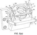
- Figures 5(a) and (b) illustrate a modification to the filler assembly 25 of Figures 4(a) to (e) .
- the slide element 61 comprises at least one slide part 64 which is slideably rotated about at least one pivot 65, here comprising first and second slide parts 64a, b which are rotated about first and second pivots 65a, b, and the loading/unloading mechanism 51 further comprises a guide member 66 which acts to cause the slide parts 64a, b to slide laterally when the loading/unloading mechanism 51 is moved axially between the unlocked (as illustrated in Figure 5(a) ) and locked (as illustrated in Figure 5(b) ) positions.
- each slide part 64a, b includes a projection 67, here at a distal end to the pivot 65a, b, and the guide member 66 includes at least one guide 68, here first and second guides 68a, b, which receive the projections 67 of the respective slide parts 64a, b.
- the guides 68a, b include a first guide section 69, in which the projections 67 are located when the loading/unloading mechanism 51 is in the unlocked position, and a second guide section 70 which is disposed laterally inwardly of the first guide section 69, in which the projections 67 are located when the loading/unloading mechanism 51 is in the locked position.
- the projections 67 of the slide parts 64a, b are located in the first guide sections 69 of the guides 68a, b and the slide parts 64a, b have a first, laterally-outward position which allows the neck K of the filling container F to be inserted into the bore 41 of the valve assembly 37, and, when the loading/unloading mechanism 51 is moved to the locked position, in this embodiment by axial displacement of the engagement member 53, the projections 67 of the slide parts 64a, b are located in the second guide sections 70 of the guides 68a, b and the slide parts 64a, b have a second, laterally-inward position in which the neck K of the filling container F is engaged by the slide parts 64a, b and prevents release of the filling container F during a filling operation.
- the projections 67 of the slide parts 64a, b are returned to the first guide sections 69 of the guides 68a, b and the slide parts 64a, b have the first, laterally-outward position which allows the neck K of the filling container F to be removed from the bore 41 of the valve assembly 37.
- the guides 68a, b each have the form of a track, here formed by a through slot.
- valve assembly 27 comprises a shut-off valve 71 which is operated as required to prevent delivery of the vaporized medium into the fresh gas flow, and a metering valve 72 which regulates the amount of the vaporized medium which is metered into the fresh gas flow in accordance the measured flow rate of the fresh gas flow, as will be described in more detail hereinbelow.
- shut-off valve 71 includes an inlet port 73 which is fluidly connected to the tank 21 of the reservoir unit 5 through a flow path in the manifold 10, and an outlet port 74 which is fluidly connected to an inlet port 75 of the metering valve 72 through a flow path in the manifold 10.
- the metering valve 72 includes an inlet port 75 which is fluidly connected to the outlet port 74 of the shut-off valve 72 through a flow path in the manifold 10, and an outlet port 76 which is fluidly connected to the vaporized medium sensing unit 9 through a flow path in the manifold 10.
- the fresh gas sensing unit 7 comprises a fresh gas inlet port 77 through which the flow of fresh gas is delivered, an outlet port 78 from which the flow of fresh gas is delivered, a flow path 79 which fluidly connects the fresh gas inlet port 77 and the outlet port 78, and at least one flow rate sensor 80 for sensing the flow rate of the fresh gas flow.
- the flow path 79 has a diameter of 5 mm.
- the fresh gas sensing unit 7 comprises at least one pair of flow rate sensors 80, here first and second pairs of flow rate sensors 80a, 80b.
- the flow rate sensors 80a, 80b are mass flow rate sensors, here mass flow sensors, which comprise a heater element and a temperature sensor element.
- the fresh gas sensing unit 7 can provide a more accurate measurement.
- the present inventors have determined that a more accurate measurement can be obtained by configuring the pair of flow rate sensors 80 such as to utilize the heater and temperature sensor elements of the downstream sensor 80 and only the temperature sensor element of the upstream sensor 80 in performing a flow rate measurement.
- the upstream sensor 80 is configured to sense the ambient temperature of the fresh gas flow and the downstream sensor 80 is configured to determine the energy required to maintain the heater element at a required temperature differential in relation to the ambient temperature as determined by the upstream sensor 80, which energy determines the flow rate of the fresh gas flow.
- the downstream sensor 80 heats the fresh gas flow to a predetermined temperature differential in relation to, here 30 °C above, the ambient temperature as determined by the upstream sensor 80.
- a control check is provided, in that the control system can monitor the output of each of the pairs of flow rate sensors 80a, 80b, and, if the measured output exceeds a predetermined threshold, raise an alert and/or shut down the vaporizer.
- the flow path 79 includes a stub path 81, and the fresh gas sensing unit 7 further comprises at least one fresh gas characteristic sensor 83 in the stub path 81.
- the stub path 81 is downstream of the at least one flow rate sensor 80a, 80b.
- the stub path 81 could be upstream of the at least one flow rate sensor 80a, 80b.
- the stub path 81 is located in a substantially linear section of the flow path 79.
- the stub path 81 comprises a sensor cavity 85 at which the at least one fresh gas characteristic sensor 83 is located, and a flow restriction 87 which fluidly connects the flow path 79 to the sensor cavity 85.
- the at least one fresh gas characteristic sensor 83 is a mass flow rate sensor, here a mass flow sensor. In this embodiment the at least one fresh gas characteristic sensor 83 is of the same kind as the flow rate sensors 80a, 80b.
- the flow restriction 87 comprises a flow channel of smaller diameter than the flow path 79, here of a diameter of 1.75 mm.
- the flow restriction has an area of about 1.5 mm 2 to about 3.5 mm 2 , preferably about 2 mm 2 to about 3 mm 2 .
- the flow restriction 87 provides for an extended residence time of the fresh gas in the sensor cavity 85, which in effect provides that the at least one fresh gas characteristic sensor 83 provides for a "zero flow” or "static" measurement of a characteristic of the gas flow which is representative of composition.
- the average residence time in the sensor cavity 85 is at least 20 seconds, optionally at least 25 seconds, optionally at least 30 seconds, and optionally at most 60 seconds.
- the average residence time in the sensor cavity 85 is at most 60 seconds, optionally at most 40 seconds, and optionally at most 35 seconds.
- the measurement from the at least one fresh gas characteristic sensor 83 provides a compensation factor, and, for this compensation factor, a look-up table is selected, from which a compensated flow rate is determined.
- the compensation factor can be applied to a fitted function for a flow rate as measured by the flow rate sensors 80a, 80b.
- the measurement from the at least one fresh gas characteristic sensor 83 provides a compensation factor, and, for this compensation factor, a look-up table is selected, from which a compensated flow rate is determined and applied to a fitted function for a flow rate as measured by the flow rate sensors 80a, 80b.
- the fresh gas sensing unit 7 includes a vaporized medium inlet port 89 in the flow path 79 thereof and downstream of the at least one fresh gas characteristic sensor 83, which is fluidly connected to the outlet port 97 of the vaporized medium sensing unit 9, by which the vaporized medium is metered into the flow of fresh gas.
- the flow restriction 87 could comprise a porous element 91, here a sintered element, which is located in the stub path 81.
- the vaporized medium sensing unit 9 comprises a body 92 which includes a flow channel 93 which includes an inlet port 95 which is fluidly connected to the outlet port 76 of the metering valve 72 and an outlet port 97 through which a flow of the vaporized medium is delivered, and at least one flow sensor 101 for detecting a flow rate of the vaporized medium through the flow channel 93.
- the body 92 comprises first and second body parts 103a, b and an annular seal 105 which surrounds the flow channel 93.
- At least one of the first and second body parts 103a, b of the body 92 is formed of a material of high thermal conductivity.
- At least one of the first and second body parts 103a, b of the body 92 is formed of the same material as the tank 21 of the reservoir unit 5.
- the at least one of the first and second body parts 103a, b of the body 92 is thermally connected, here fixed directly, to the tank 21 of the reservoir unit 5.
- the body 92 is maintained in a heated state, which prevents condensation in the flow channel 93, which could hinder accurate detection of the flow rate of the vaporized medium.
- the flow channel 93 is a linear channel.
- the flow channel 93 has a cross-sectional area of 2 mm 2 , and in preferred embodiments has a cross-sectional area from about 1.5 mm 2 to about 2.5 mm 2 . This configuration has been found to provide for establishment of a laminar flow over the at least one flow sensor 101 for a broad range of flows.
- the at least one flow sensor 101 is a mass flow rate sensor, here a mass flow sensor.
- the vaporized medium sensing unit 9 includes first and second flow sensors 101a, b.
- first and second flow sensors 101a, b By providing first and second flow sensors 101a, b, a control check is provided, in that the control system can monitor the output of each of the flow sensors 101a, b, and, if the measured output exceeds a predetermined threshold, raise an alert and/or shut down the vaporizer.
- the manifold 10 comprises a thermal block 111 of a material of high thermal conductivity which includes flow passages for the vaporized medium.
- the manifold 10 is maintained in a heated state, which prevents condensation of the vaporized medium in the flow passages.
- the thermal block 111 is formed of the same material as the tank 21 of the reservoir unit 5.
- the manifold 10 includes a connector 115 which fluidly connects the outlet port 97 of the vaporized medium sensing unit 9, here through a flow passage in the thermal block 111, to vaporized medium inlet port 89 in the flow path 79 of the fresh gas sensing unit 7.
- the connector 115 is formed of the same material as the tank 21 of the reservoir unit 5.
- the present invention has been described with reference to the delivery of a general anaesthetic, it will be understood that the present invention has application to the vaporization of any medium for delivery in a gas flow.
Landscapes
- Health & Medical Sciences (AREA)
- Anesthesiology (AREA)
- Engineering & Computer Science (AREA)
- General Health & Medical Sciences (AREA)
- Life Sciences & Earth Sciences (AREA)
- Animal Behavior & Ethology (AREA)
- Public Health (AREA)
- Emergency Medicine (AREA)
- Biomedical Technology (AREA)
- Heart & Thoracic Surgery (AREA)
- Hematology (AREA)
- Veterinary Medicine (AREA)
- Pulmonology (AREA)
- Physics & Mathematics (AREA)
- General Physics & Mathematics (AREA)
- Fluid Mechanics (AREA)
- Automation & Control Theory (AREA)
- Chemical & Material Sciences (AREA)
- Analytical Chemistry (AREA)
- Biochemistry (AREA)
- Immunology (AREA)
- Pathology (AREA)
- Chemical Vapour Deposition (AREA)
- Filling Or Discharging Of Gas Storage Vessels (AREA)
- Feeding, Discharge, Calcimining, Fusing, And Gas-Generation Devices (AREA)
Claims (7)
- Verdampfer, welcher umfasst:eine Gaszufuhreinheit (3), die ausgestaltet ist, einen ersten Gasstrom zu empfangen und einen zweiten Gasstrom bereitzustellen, der eine abgemessene Menge eines verdampften Mediums enthält;eine Speichereinheit (5), die ein flüchtiges Medium enthält und ausgestaltet ist, eine Bereitstellung des verdampften Mediums aufrechtzuerhalten, worin die Speichereinheit (5) selektiv mit der Gaszufuhreinheit in Fluidverbindung steht,worin die Speichereinheit (5) umfasst:einen Tank (21), der das flüchtige Medium in flüssiger Form enthält;eine Heizvorrichtung (23), die das flüchtige Medium auf eine Verdampfungstemperatur erhitzt, um das flüchtige Medium zu verdampfen und einen Betriebsdruck in einem Kopfraum des Tanks (21) aufrechtzuerhalten;und eine Ventilanordnung (27), die ausgestaltet ist, das verdampfte Medium aus dem Tank (21) in den ersten Gasstrom zu dosieren, um den zweiten Gasstrom zu erzeugen;eine erste Gassensoreinheit (7), die ausgestaltet ist, eine Durchflussrate und/oder eine Zusammensetzung des ersten Gasstroms zu erfassen;eine Erfassungseinheit für verdampftes Medium (9), die ausgestaltet ist, eine Durchflussmenge des verdampften Mediums zu erfassen, das von der Ventilanordnung dosiert wird;einen Verteiler (10), der Strömungswege für das verdampfte Medium enthält und die Speichereinheit (5) und die Erfassungseinheit (9) für verdampftes Medium fluidmäßig verbindet; undeine Steuereinheit (11), die ausgestaltet ist, eine Durchflussrate des ersten Gasstroms und eine Menge des verdampften Mediums zu steuern, die von der Ventilanordnung (27) aus dem Tank (21) in den ersten Gasstrom dosiert wird, um den zweiten Gasstrom zu erzeugen; worin der Tank (21) aus einem thermisch leitfähigen Material ausgebildet ist;dadurch gekennzeichnet, dass:
der Tank (21) eine thermische Masse bereitstellt, die ausreicht, um das enthaltene flüchtige Medium für eine bestimmte Zeitspanne von mindestens 3 Minuten nach Abschalten der Heizvorrichtung (23) auf der Verdampfungstemperatur zu halten. - Verdampfer nach Anspruch 1, worin die Gaszufuhreinheit (3) einen Einlass (15), der mit einer ersten Gasversorgung verbunden ist, und einen Auslass (17) umfasst, der ausgestaltet ist, den zweiten Gasstrom zu liefern.
- Verdampfer nach Anspruch 1 oder 2, worin die bestimmte Zeitspanne mindestens 5 Minuten beträgt.
- Verdampfer nach einem der Ansprüche 1 bis 3, worin die erste Gassensoreinheit (7) umfasst:eine erste Gaseinlassöffnung (77), die ausgestaltet ist, dass der erste Gasstrom bei Verwendung durch die erste Gaseinlassöffnung zugeführt wird;eine Auslassöffnung (78), die ausgestaltet ist, dass der zweite Gasstrom bei Verwendung von der Auslassöffnung (78) abgegeben wird;einen Strömungspfad (79), der die erste Gaseinlassöffnung (77) und die Auslassöffnung (78) fluidmäßig verbindet;und mindestens einen Durchflusssensor (80), der ausgestaltet ist, die Durchflussmenge des ersten Gasstroms zu erfassen.
- Verdampfer nach Anspruch 4, worin der Strömungspfad (79) eine Stichleitung (81) aufweist und die erste Gassensoreinheit (7) ferner mindestens einen ersten Gascharakteristiksensor (83) in der Stichleitung (81) aufweist, wobei der mindestens eine erste Gascharakteristiksensor (83) ausgestaltet ist, eine Charakteristik des ersten Gasstroms zu messen, die für die Zusammensetzung des ersten Gasstroms repräsentativ ist, wobei die Messung von dem ersten Gascharakteristiksensor (83) einen Kompensationsfaktor für die Strömungsrate des ersten Gasstroms bereitstellt, wie von dem mindestens einen Durchflusssensor (80) erfasst wurde.
- Verdampfer nach Anspruch 4, worin die erste Gassensoreinheit (7) eine Einlassöffnung (89) für verdampftes Medium in ihrem Strömungspfad (79) und stromabwärts des mindestens einen ersten Gascharakteristiksensors (83) aufweist, der mit der Erfassungseinheit (9) für verdampftes Medium in Fluidverbindung steht.
- Verdampfer nach einem der Ansprüche 1 bis 6, der ausgestaltet ist, dass das verdampfte Medium mit einer Durchflussrate von 1 L/min abgegeben werden kann, und
worin der Tank (21) ausgestaltet ist, das enthaltene flüchtige Medium für die bestimmte Zeitspanne nach der Abschaltung der Heizvorrichtung (23) auf der Verdampfungstemperatur zu halten, wenn das verdampfte Medium mit einer Durchflussrate von 1 L/min zugeführt wird.
Applications Claiming Priority (2)
| Application Number | Priority Date | Filing Date | Title |
|---|---|---|---|
| GB1409274.6A GB2526539B (en) | 2014-05-23 | 2014-05-23 | Vaporizer |
| PCT/EP2015/061606 WO2015177381A2 (en) | 2014-05-23 | 2015-05-26 | Vaporizer |
Publications (2)
| Publication Number | Publication Date |
|---|---|
| EP3145569A2 EP3145569A2 (de) | 2017-03-29 |
| EP3145569B1 true EP3145569B1 (de) | 2021-11-17 |
Family
ID=51177410
Family Applications (1)
| Application Number | Title | Priority Date | Filing Date |
|---|---|---|---|
| EP15730698.6A Active EP3145569B1 (de) | 2014-05-23 | 2015-05-26 | Verdampfer |
Country Status (5)
| Country | Link |
|---|---|
| US (1) | US10328230B2 (de) |
| EP (1) | EP3145569B1 (de) |
| CN (1) | CN106659866B (de) |
| GB (1) | GB2526539B (de) |
| WO (1) | WO2015177381A2 (de) |
Families Citing this family (4)
| Publication number | Priority date | Publication date | Assignee | Title |
|---|---|---|---|---|
| US11197973B2 (en) | 2019-02-12 | 2021-12-14 | GE Precision Healthcare LLC | System and method for monitoring filling status of a vaporizer reservoir in an anesthetic vaporizer system |
| EP3821933A1 (de) * | 2019-11-18 | 2021-05-19 | Oxypoint NV | Gasventilsystem mit durchflusssensor |
| US11324913B2 (en) | 2019-11-15 | 2022-05-10 | GE Precision Healthcare LLC | Systems and methods for filling an anesthesia vaporizer using an ullage volume and vent |
| US11759599B2 (en) * | 2020-06-26 | 2023-09-19 | GE Precision Healthcare LLC | Systems and method for valve control in a fill assembly of a medical device |
Family Cites Families (18)
| Publication number | Priority date | Publication date | Assignee | Title |
|---|---|---|---|---|
| GB1237014A (en) * | 1969-02-05 | 1971-06-30 | Pye Ltd | Improvements in or relating to medical respirators |
| US4881541A (en) | 1988-12-21 | 1989-11-21 | The Regents Of The University Of California | Vaporizer for an anesthetic having a vapor pressure about one atmosphere |
| DE3924123C2 (de) * | 1989-07-20 | 1994-01-27 | Draegerwerk Ag | Vorrichtung zur Erzeugung und Dosierung eines Gasgemisches |
| SE9100016D0 (sv) * | 1991-01-03 | 1991-01-03 | Olof Werner | Foerfarande och anordning att reglera inandad koncentration av gas i en anestesikrets |
| FI92468C (fi) * | 1991-11-15 | 1994-11-25 | Instrumentarium Oy | Laitteisto anestesia-aineen annostelemiseksi potilaalle |
| FI104411B (fi) * | 1995-01-23 | 2000-01-31 | Instrumentarium Oy | Sovitelma anesteetin höyrystämisen yhteydessä |
| SE9801074D0 (sv) * | 1998-03-27 | 1998-03-27 | Siemens Elema Ab | Dosing device |
| FI106435B (fi) * | 1999-04-15 | 2001-02-15 | Instrumentarium Oyj | Menetelmä ja sovitelma anestesialaitteen yhteydessä |
| GB0308661D0 (en) * | 2003-04-15 | 2003-05-21 | Penlon Ltd | Improved anaesthetic vaporizer |
| US6945123B1 (en) * | 2004-06-28 | 2005-09-20 | The General Electric Company | Gas flow sensor having redundant flow sensing capability |
| WO2008151667A1 (en) * | 2007-06-13 | 2008-12-18 | Maquet Critical Care Ab | A safety system for a breathing apparatus for delivering an anesthetic agent |
| EP2461861B1 (de) * | 2009-08-03 | 2019-03-20 | Colin Dunlop | Verbesserte vorrichtung zur flüssigkeitsabgabe an einen patienten |
| KR101138957B1 (ko) | 2009-12-16 | 2012-04-25 | 주식회사 멕 아이씨에스 | 마취기의 전자식 기화 장치 |
| US8327892B2 (en) * | 2010-01-29 | 2012-12-11 | General Electric Company | Vaporizer filler lock and method of filling a vaporizer |
| US20110315139A1 (en) * | 2010-06-23 | 2011-12-29 | General Electric Company | Automatic fresh gas control system |
| CN202277596U (zh) | 2011-10-31 | 2012-06-20 | 刘瑞全 | 一种吸入麻醉装置 |
| US10426913B2 (en) * | 2011-11-07 | 2019-10-01 | Mallinckrodt Hospital Products IP Limited | Apparatus and method for monitoring nitric oxide delivery |
| JP6142629B2 (ja) * | 2013-03-29 | 2017-06-07 | 東京エレクトロン株式会社 | 原料ガス供給装置、成膜装置及び原料ガス供給方法 |
-
2014
- 2014-05-23 GB GB1409274.6A patent/GB2526539B/en active Active
-
2015
- 2015-05-26 CN CN201580033747.XA patent/CN106659866B/zh active Active
- 2015-05-26 WO PCT/EP2015/061606 patent/WO2015177381A2/en not_active Ceased
- 2015-05-26 US US15/313,620 patent/US10328230B2/en active Active
- 2015-05-26 EP EP15730698.6A patent/EP3145569B1/de active Active
Non-Patent Citations (1)
| Title |
|---|
| None * |
Also Published As
| Publication number | Publication date |
|---|---|
| GB2526539A (en) | 2015-12-02 |
| WO2015177381A2 (en) | 2015-11-26 |
| EP3145569A2 (de) | 2017-03-29 |
| CN106659866A (zh) | 2017-05-10 |
| US20170182281A1 (en) | 2017-06-29 |
| GB2526539B (en) | 2016-11-02 |
| GB201409274D0 (en) | 2014-07-09 |
| WO2015177381A3 (en) | 2016-01-21 |
| CN106659866B (zh) | 2023-03-24 |
| US10328230B2 (en) | 2019-06-25 |
Similar Documents
| Publication | Publication Date | Title |
|---|---|---|
| CA2033770C (en) | Anaesthetic vaporisers | |
| US20220062579A1 (en) | Systems for anesthetic agent vaporization | |
| EP3145569B1 (de) | Verdampfer | |
| US5771882A (en) | Anesthetic administration apparatus which delivers anesthetic in microdroplets | |
| US11896773B2 (en) | Vaporizer arrangement for a breathing apparatus | |
| JPH0124511B2 (de) | ||
| JPH0632659B2 (ja) | 麻酔剤気化器 | |
| US5168866A (en) | Vaporizers usable with anesthetics having a boiling point near the ambient temperature | |
| US20140083420A1 (en) | Inhalation anesthetic vaporizer | |
| EP1082973B1 (de) | Narkosemittelverdunster | |
| US7886780B2 (en) | Method and apparatus for preventing drug reservoir overfill | |
| WO2004091708A2 (en) | Improved anaesthetic vaporizer | |
| US8327892B2 (en) | Vaporizer filler lock and method of filling a vaporizer | |
| JP7473706B2 (ja) | 制御された濃度で送達を行うための気化システム | |
| CN218106538U (zh) | 一种麻醉蒸发器及麻醉机 | |
| US12343478B2 (en) | Anesthetic dispenser with mixing unit and anesthetic tank and process using anesthetic dispenser | |
| JP2005279218A (ja) | 小実験動物用吸入麻酔装置 | |
| US6298845B1 (en) | Vaporizer | |
| US20260115406A1 (en) | Arrangement and process for artificial ventilation of a patient with reduced risk of condensation |
Legal Events
| Date | Code | Title | Description |
|---|---|---|---|
| STAA | Information on the status of an ep patent application or granted ep patent |
Free format text: STATUS: THE INTERNATIONAL PUBLICATION HAS BEEN MADE |
|
| PUAI | Public reference made under article 153(3) epc to a published international application that has entered the european phase |
Free format text: ORIGINAL CODE: 0009012 |
|
| STAA | Information on the status of an ep patent application or granted ep patent |
Free format text: STATUS: REQUEST FOR EXAMINATION WAS MADE |
|
| 17P | Request for examination filed |
Effective date: 20161208 |
|
| AK | Designated contracting states |
Kind code of ref document: A2 Designated state(s): AL AT BE BG CH CY CZ DE DK EE ES FI FR GB GR HR HU IE IS IT LI LT LU LV MC MK MT NL NO PL PT RO RS SE SI SK SM TR |
|
| AX | Request for extension of the european patent |
Extension state: BA ME |
|
| DAV | Request for validation of the european patent (deleted) | ||
| DAX | Request for extension of the european patent (deleted) | ||
| STAA | Information on the status of an ep patent application or granted ep patent |
Free format text: STATUS: EXAMINATION IS IN PROGRESS |
|
| 17Q | First examination report despatched |
Effective date: 20190603 |
|
| GRAP | Despatch of communication of intention to grant a patent |
Free format text: ORIGINAL CODE: EPIDOSNIGR1 |
|
| STAA | Information on the status of an ep patent application or granted ep patent |
Free format text: STATUS: GRANT OF PATENT IS INTENDED |
|
| RIC1 | Information provided on ipc code assigned before grant |
Ipc: A61M 16/18 20060101AFI20210622BHEP Ipc: A61M 16/10 20060101ALI20210622BHEP Ipc: A61M 16/14 20060101ALI20210622BHEP Ipc: A61M 16/16 20060101ALI20210622BHEP Ipc: G01F 1/68 20060101ALI20210622BHEP Ipc: G01F 15/00 20060101ALI20210622BHEP Ipc: G01F 15/14 20060101ALI20210622BHEP Ipc: G05D 7/06 20060101ALI20210622BHEP Ipc: A61M 16/20 20060101ALN20210622BHEP |
|
| INTG | Intention to grant announced |
Effective date: 20210713 |
|
| GRAS | Grant fee paid |
Free format text: ORIGINAL CODE: EPIDOSNIGR3 |
|
| GRAA | (expected) grant |
Free format text: ORIGINAL CODE: 0009210 |
|
| STAA | Information on the status of an ep patent application or granted ep patent |
Free format text: STATUS: THE PATENT HAS BEEN GRANTED |
|
| AK | Designated contracting states |
Kind code of ref document: B1 Designated state(s): AL AT BE BG CH CY CZ DE DK EE ES FI FR GB GR HR HU IE IS IT LI LT LU LV MC MK MT NL NO PL PT RO RS SE SI SK SM TR |
|
| REG | Reference to a national code |
Ref country code: GB Ref legal event code: FG4D |
|
| REG | Reference to a national code |
Ref country code: DE Ref legal event code: R096 Ref document number: 602015075066 Country of ref document: DE |
|
| REG | Reference to a national code |
Ref country code: IE Ref legal event code: FG4D |
|
| REG | Reference to a national code |
Ref country code: AT Ref legal event code: REF Ref document number: 1447544 Country of ref document: AT Kind code of ref document: T Effective date: 20211215 |
|
| REG | Reference to a national code |
Ref country code: LT Ref legal event code: MG9D |
|
| REG | Reference to a national code |
Ref country code: NL Ref legal event code: MP Effective date: 20211117 |
|
| REG | Reference to a national code |
Ref country code: AT Ref legal event code: MK05 Ref document number: 1447544 Country of ref document: AT Kind code of ref document: T Effective date: 20211117 |
|
| PG25 | Lapsed in a contracting state [announced via postgrant information from national office to epo] |
Ref country code: RS Free format text: LAPSE BECAUSE OF FAILURE TO SUBMIT A TRANSLATION OF THE DESCRIPTION OR TO PAY THE FEE WITHIN THE PRESCRIBED TIME-LIMIT Effective date: 20211117 Ref country code: LT Free format text: LAPSE BECAUSE OF FAILURE TO SUBMIT A TRANSLATION OF THE DESCRIPTION OR TO PAY THE FEE WITHIN THE PRESCRIBED TIME-LIMIT Effective date: 20211117 Ref country code: FI Free format text: LAPSE BECAUSE OF FAILURE TO SUBMIT A TRANSLATION OF THE DESCRIPTION OR TO PAY THE FEE WITHIN THE PRESCRIBED TIME-LIMIT Effective date: 20211117 Ref country code: BG Free format text: LAPSE BECAUSE OF FAILURE TO SUBMIT A TRANSLATION OF THE DESCRIPTION OR TO PAY THE FEE WITHIN THE PRESCRIBED TIME-LIMIT Effective date: 20220217 Ref country code: AT Free format text: LAPSE BECAUSE OF FAILURE TO SUBMIT A TRANSLATION OF THE DESCRIPTION OR TO PAY THE FEE WITHIN THE PRESCRIBED TIME-LIMIT Effective date: 20211117 |
|
| REG | Reference to a national code |
Ref country code: FR Ref legal event code: PLFP Year of fee payment: 8 |
|
| PG25 | Lapsed in a contracting state [announced via postgrant information from national office to epo] |
Ref country code: IS Free format text: LAPSE BECAUSE OF FAILURE TO SUBMIT A TRANSLATION OF THE DESCRIPTION OR TO PAY THE FEE WITHIN THE PRESCRIBED TIME-LIMIT Effective date: 20220317 Ref country code: SE Free format text: LAPSE BECAUSE OF FAILURE TO SUBMIT A TRANSLATION OF THE DESCRIPTION OR TO PAY THE FEE WITHIN THE PRESCRIBED TIME-LIMIT Effective date: 20211117 Ref country code: PT Free format text: LAPSE BECAUSE OF FAILURE TO SUBMIT A TRANSLATION OF THE DESCRIPTION OR TO PAY THE FEE WITHIN THE PRESCRIBED TIME-LIMIT Effective date: 20220317 Ref country code: PL Free format text: LAPSE BECAUSE OF FAILURE TO SUBMIT A TRANSLATION OF THE DESCRIPTION OR TO PAY THE FEE WITHIN THE PRESCRIBED TIME-LIMIT Effective date: 20211117 Ref country code: NO Free format text: LAPSE BECAUSE OF FAILURE TO SUBMIT A TRANSLATION OF THE DESCRIPTION OR TO PAY THE FEE WITHIN THE PRESCRIBED TIME-LIMIT Effective date: 20220217 Ref country code: NL Free format text: LAPSE BECAUSE OF FAILURE TO SUBMIT A TRANSLATION OF THE DESCRIPTION OR TO PAY THE FEE WITHIN THE PRESCRIBED TIME-LIMIT Effective date: 20211117 Ref country code: LV Free format text: LAPSE BECAUSE OF FAILURE TO SUBMIT A TRANSLATION OF THE DESCRIPTION OR TO PAY THE FEE WITHIN THE PRESCRIBED TIME-LIMIT Effective date: 20211117 Ref country code: HR Free format text: LAPSE BECAUSE OF FAILURE TO SUBMIT A TRANSLATION OF THE DESCRIPTION OR TO PAY THE FEE WITHIN THE PRESCRIBED TIME-LIMIT Effective date: 20211117 Ref country code: GR Free format text: LAPSE BECAUSE OF FAILURE TO SUBMIT A TRANSLATION OF THE DESCRIPTION OR TO PAY THE FEE WITHIN THE PRESCRIBED TIME-LIMIT Effective date: 20220218 Ref country code: ES Free format text: LAPSE BECAUSE OF FAILURE TO SUBMIT A TRANSLATION OF THE DESCRIPTION OR TO PAY THE FEE WITHIN THE PRESCRIBED TIME-LIMIT Effective date: 20211117 |
|
| PG25 | Lapsed in a contracting state [announced via postgrant information from national office to epo] |
Ref country code: SM Free format text: LAPSE BECAUSE OF FAILURE TO SUBMIT A TRANSLATION OF THE DESCRIPTION OR TO PAY THE FEE WITHIN THE PRESCRIBED TIME-LIMIT Effective date: 20211117 Ref country code: SK Free format text: LAPSE BECAUSE OF FAILURE TO SUBMIT A TRANSLATION OF THE DESCRIPTION OR TO PAY THE FEE WITHIN THE PRESCRIBED TIME-LIMIT Effective date: 20211117 Ref country code: RO Free format text: LAPSE BECAUSE OF FAILURE TO SUBMIT A TRANSLATION OF THE DESCRIPTION OR TO PAY THE FEE WITHIN THE PRESCRIBED TIME-LIMIT Effective date: 20211117 Ref country code: EE Free format text: LAPSE BECAUSE OF FAILURE TO SUBMIT A TRANSLATION OF THE DESCRIPTION OR TO PAY THE FEE WITHIN THE PRESCRIBED TIME-LIMIT Effective date: 20211117 Ref country code: DK Free format text: LAPSE BECAUSE OF FAILURE TO SUBMIT A TRANSLATION OF THE DESCRIPTION OR TO PAY THE FEE WITHIN THE PRESCRIBED TIME-LIMIT Effective date: 20211117 Ref country code: CZ Free format text: LAPSE BECAUSE OF FAILURE TO SUBMIT A TRANSLATION OF THE DESCRIPTION OR TO PAY THE FEE WITHIN THE PRESCRIBED TIME-LIMIT Effective date: 20211117 |
|
| REG | Reference to a national code |
Ref country code: DE Ref legal event code: R097 Ref document number: 602015075066 Country of ref document: DE |
|
| PLBE | No opposition filed within time limit |
Free format text: ORIGINAL CODE: 0009261 |
|
| STAA | Information on the status of an ep patent application or granted ep patent |
Free format text: STATUS: NO OPPOSITION FILED WITHIN TIME LIMIT |
|
| 26N | No opposition filed |
Effective date: 20220818 |
|
| PG25 | Lapsed in a contracting state [announced via postgrant information from national office to epo] |
Ref country code: AL Free format text: LAPSE BECAUSE OF FAILURE TO SUBMIT A TRANSLATION OF THE DESCRIPTION OR TO PAY THE FEE WITHIN THE PRESCRIBED TIME-LIMIT Effective date: 20211117 |
|
| PG25 | Lapsed in a contracting state [announced via postgrant information from national office to epo] |
Ref country code: SI Free format text: LAPSE BECAUSE OF FAILURE TO SUBMIT A TRANSLATION OF THE DESCRIPTION OR TO PAY THE FEE WITHIN THE PRESCRIBED TIME-LIMIT Effective date: 20211117 |
|
| REG | Reference to a national code |
Ref country code: CH Ref legal event code: PL |
|
| REG | Reference to a national code |
Ref country code: BE Ref legal event code: MM Effective date: 20220531 |
|
| PG25 | Lapsed in a contracting state [announced via postgrant information from national office to epo] |
Ref country code: MC Free format text: LAPSE BECAUSE OF FAILURE TO SUBMIT A TRANSLATION OF THE DESCRIPTION OR TO PAY THE FEE WITHIN THE PRESCRIBED TIME-LIMIT Effective date: 20211117 Ref country code: LU Free format text: LAPSE BECAUSE OF NON-PAYMENT OF DUE FEES Effective date: 20220526 Ref country code: LI Free format text: LAPSE BECAUSE OF NON-PAYMENT OF DUE FEES Effective date: 20220531 Ref country code: CH Free format text: LAPSE BECAUSE OF NON-PAYMENT OF DUE FEES Effective date: 20220531 |
|
| PG25 | Lapsed in a contracting state [announced via postgrant information from national office to epo] |
Ref country code: IE Free format text: LAPSE BECAUSE OF NON-PAYMENT OF DUE FEES Effective date: 20220526 |
|
| PG25 | Lapsed in a contracting state [announced via postgrant information from national office to epo] |
Ref country code: IT Free format text: LAPSE BECAUSE OF FAILURE TO SUBMIT A TRANSLATION OF THE DESCRIPTION OR TO PAY THE FEE WITHIN THE PRESCRIBED TIME-LIMIT Effective date: 20211117 Ref country code: BE Free format text: LAPSE BECAUSE OF NON-PAYMENT OF DUE FEES Effective date: 20220531 |
|
| P01 | Opt-out of the competence of the unified patent court (upc) registered |
Effective date: 20230510 |
|
| PG25 | Lapsed in a contracting state [announced via postgrant information from national office to epo] |
Ref country code: HU Free format text: LAPSE BECAUSE OF FAILURE TO SUBMIT A TRANSLATION OF THE DESCRIPTION OR TO PAY THE FEE WITHIN THE PRESCRIBED TIME-LIMIT; INVALID AB INITIO Effective date: 20150526 |
|
| PG25 | Lapsed in a contracting state [announced via postgrant information from national office to epo] |
Ref country code: MK Free format text: LAPSE BECAUSE OF FAILURE TO SUBMIT A TRANSLATION OF THE DESCRIPTION OR TO PAY THE FEE WITHIN THE PRESCRIBED TIME-LIMIT Effective date: 20211117 Ref country code: CY Free format text: LAPSE BECAUSE OF FAILURE TO SUBMIT A TRANSLATION OF THE DESCRIPTION OR TO PAY THE FEE WITHIN THE PRESCRIBED TIME-LIMIT Effective date: 20211117 |
|
| PG25 | Lapsed in a contracting state [announced via postgrant information from national office to epo] |
Ref country code: TR Free format text: LAPSE BECAUSE OF FAILURE TO SUBMIT A TRANSLATION OF THE DESCRIPTION OR TO PAY THE FEE WITHIN THE PRESCRIBED TIME-LIMIT Effective date: 20211117 |
|
| REG | Reference to a national code |
Ref country code: DE Ref legal event code: R082 Ref document number: 602015075066 Country of ref document: DE Representative=s name: STRAUS, ALEXANDER, DIPL.-CHEM.UNIV. DR.PHIL., DE |
|
| PG25 | Lapsed in a contracting state [announced via postgrant information from national office to epo] |
Ref country code: MT Free format text: LAPSE BECAUSE OF FAILURE TO SUBMIT A TRANSLATION OF THE DESCRIPTION OR TO PAY THE FEE WITHIN THE PRESCRIBED TIME-LIMIT Effective date: 20211117 |
|
| PGFP | Annual fee paid to national office [announced via postgrant information from national office to epo] |
Ref country code: DE Payment date: 20250521 Year of fee payment: 11 |
|
| PGFP | Annual fee paid to national office [announced via postgrant information from national office to epo] |
Ref country code: FR Payment date: 20250528 Year of fee payment: 11 |
|
| PGFP | Annual fee paid to national office [announced via postgrant information from national office to epo] |
Ref country code: GB Payment date: 20260310 Year of fee payment: 12 |