EP3145606B1 - Procédé et appareil de séparation de no2 d'un fluide contenant du co2 et du no2 - Google Patents
Procédé et appareil de séparation de no2 d'un fluide contenant du co2 et du no2 Download PDFInfo
- Publication number
- EP3145606B1 EP3145606B1 EP15716304.9A EP15716304A EP3145606B1 EP 3145606 B1 EP3145606 B1 EP 3145606B1 EP 15716304 A EP15716304 A EP 15716304A EP 3145606 B1 EP3145606 B1 EP 3145606B1
- Authority
- EP
- European Patent Office
- Prior art keywords
- stream
- gaseous
- liquid
- fluid
- poly
- Prior art date
- Legal status (The legal status is an assumption and is not a legal conclusion. Google has not performed a legal analysis and makes no representation as to the accuracy of the status listed.)
- Active
Links
- 0 CC(C)(C)[N+](C(C1)C1(C1)*1[N+]([O-])O*)[O-] Chemical compound CC(C)(C)[N+](C(C1)C1(C1)*1[N+]([O-])O*)[O-] 0.000 description 1
Images

Classifications
-
- B—PERFORMING OPERATIONS; TRANSPORTING
- B01—PHYSICAL OR CHEMICAL PROCESSES OR APPARATUS IN GENERAL
- B01D—SEPARATION
- B01D19/00—Degasification of liquids
- B01D19/0031—Degasification of liquids by filtration
-
- B—PERFORMING OPERATIONS; TRANSPORTING
- B01—PHYSICAL OR CHEMICAL PROCESSES OR APPARATUS IN GENERAL
- B01D—SEPARATION
- B01D3/00—Distillation or related exchange processes in which liquids are contacted with gaseous media, e.g. stripping
-
- B—PERFORMING OPERATIONS; TRANSPORTING
- B01—PHYSICAL OR CHEMICAL PROCESSES OR APPARATUS IN GENERAL
- B01D—SEPARATION
- B01D3/00—Distillation or related exchange processes in which liquids are contacted with gaseous media, e.g. stripping
- B01D3/14—Fractional distillation or use of a fractionation or rectification column
- B01D3/143—Fractional distillation or use of a fractionation or rectification column by two or more of a fractionation, separation or rectification step
- B01D3/145—One step being separation by permeation
-
- B—PERFORMING OPERATIONS; TRANSPORTING
- B01—PHYSICAL OR CHEMICAL PROCESSES OR APPARATUS IN GENERAL
- B01D—SEPARATION
- B01D53/00—Separation of gases or vapours; Recovering vapours of volatile solvents from gases; Chemical or biological purification of waste gases, e.g. engine exhaust gases, smoke, fumes, flue gases, aerosols
- B01D53/002—Separation of gases or vapours; Recovering vapours of volatile solvents from gases; Chemical or biological purification of waste gases, e.g. engine exhaust gases, smoke, fumes, flue gases, aerosols by condensation
-
- B—PERFORMING OPERATIONS; TRANSPORTING
- B01—PHYSICAL OR CHEMICAL PROCESSES OR APPARATUS IN GENERAL
- B01D—SEPARATION
- B01D53/00—Separation of gases or vapours; Recovering vapours of volatile solvents from gases; Chemical or biological purification of waste gases, e.g. engine exhaust gases, smoke, fumes, flue gases, aerosols
- B01D53/22—Separation of gases or vapours; Recovering vapours of volatile solvents from gases; Chemical or biological purification of waste gases, e.g. engine exhaust gases, smoke, fumes, flue gases, aerosols by diffusion
-
- B—PERFORMING OPERATIONS; TRANSPORTING
- B01—PHYSICAL OR CHEMICAL PROCESSES OR APPARATUS IN GENERAL
- B01D—SEPARATION
- B01D53/00—Separation of gases or vapours; Recovering vapours of volatile solvents from gases; Chemical or biological purification of waste gases, e.g. engine exhaust gases, smoke, fumes, flue gases, aerosols
- B01D53/22—Separation of gases or vapours; Recovering vapours of volatile solvents from gases; Chemical or biological purification of waste gases, e.g. engine exhaust gases, smoke, fumes, flue gases, aerosols by diffusion
- B01D53/229—Integrated processes (Diffusion and at least one other process, e.g. adsorption, absorption)
-
- B—PERFORMING OPERATIONS; TRANSPORTING
- B01—PHYSICAL OR CHEMICAL PROCESSES OR APPARATUS IN GENERAL
- B01D—SEPARATION
- B01D61/00—Processes of separation using semi-permeable membranes, e.g. dialysis, osmosis or ultrafiltration; Apparatus, accessories or auxiliary operations specially adapted therefor
- B01D61/36—Pervaporation; Membrane distillation; Liquid permeation
- B01D61/362—Pervaporation
-
- B—PERFORMING OPERATIONS; TRANSPORTING
- B01—PHYSICAL OR CHEMICAL PROCESSES OR APPARATUS IN GENERAL
- B01D—SEPARATION
- B01D71/00—Semi-permeable membranes for separation processes or apparatus characterised by the material; Manufacturing processes specially adapted therefor
- B01D71/06—Organic material
- B01D71/48—Polyesters
-
- B—PERFORMING OPERATIONS; TRANSPORTING
- B01—PHYSICAL OR CHEMICAL PROCESSES OR APPARATUS IN GENERAL
- B01D—SEPARATION
- B01D71/00—Semi-permeable membranes for separation processes or apparatus characterised by the material; Manufacturing processes specially adapted therefor
- B01D71/06—Organic material
- B01D71/52—Polyethers
- B01D71/521—Aliphatic polyethers
- B01D71/5211—Polyethylene glycol or polyethyleneoxide
-
- C—CHEMISTRY; METALLURGY
- C01—INORGANIC CHEMISTRY
- C01B—NON-METALLIC ELEMENTS; COMPOUNDS THEREOF; METALLOIDS OR COMPOUNDS THEREOF NOT COVERED BY SUBCLASS C01C
- C01B32/00—Carbon; Compounds thereof
- C01B32/50—Carbon dioxide
-
- F—MECHANICAL ENGINEERING; LIGHTING; HEATING; WEAPONS; BLASTING
- F25—REFRIGERATION OR COOLING; COMBINED HEATING AND REFRIGERATION SYSTEMS; HEAT PUMP SYSTEMS; MANUFACTURE OR STORAGE OF ICE; LIQUEFACTION SOLIDIFICATION OF GASES
- F25J—LIQUEFACTION, SOLIDIFICATION OR SEPARATION OF GASES OR GASEOUS OR LIQUEFIED GASEOUS MIXTURES BY PRESSURE AND COLD TREATMENT OR BY BRINGING THEM INTO THE SUPERCRITICAL STATE
- F25J3/00—Processes or apparatus for separating the constituents of gaseous or liquefied gaseous mixtures involving the use of liquefaction or solidification
- F25J3/02—Processes or apparatus for separating the constituents of gaseous or liquefied gaseous mixtures involving the use of liquefaction or solidification by rectification, i.e. by continuous interchange of heat and material between a vapour stream and a liquid stream
- F25J3/0228—Processes or apparatus for separating the constituents of gaseous or liquefied gaseous mixtures involving the use of liquefaction or solidification by rectification, i.e. by continuous interchange of heat and material between a vapour stream and a liquid stream characterised by the separated product stream
- F25J3/0266—Processes or apparatus for separating the constituents of gaseous or liquefied gaseous mixtures involving the use of liquefaction or solidification by rectification, i.e. by continuous interchange of heat and material between a vapour stream and a liquid stream characterised by the separated product stream separation of carbon dioxide
-
- B—PERFORMING OPERATIONS; TRANSPORTING
- B01—PHYSICAL OR CHEMICAL PROCESSES OR APPARATUS IN GENERAL
- B01D—SEPARATION
- B01D2256/00—Main component in the product gas stream after treatment
- B01D2256/22—Carbon dioxide
-
- B—PERFORMING OPERATIONS; TRANSPORTING
- B01—PHYSICAL OR CHEMICAL PROCESSES OR APPARATUS IN GENERAL
- B01D—SEPARATION
- B01D2257/00—Components to be removed
- B01D2257/40—Nitrogen compounds
- B01D2257/404—Nitrogen oxides other than dinitrogen oxide
-
- B—PERFORMING OPERATIONS; TRANSPORTING
- B01—PHYSICAL OR CHEMICAL PROCESSES OR APPARATUS IN GENERAL
- B01D—SEPARATION
- B01D2259/00—Type of treatment
- B01D2259/45—Gas separation or purification devices adapted for specific applications
- B01D2259/4516—Gas separation or purification devices adapted for specific applications for fuel vapour recovery systems
-
- B—PERFORMING OPERATIONS; TRANSPORTING
- B01—PHYSICAL OR CHEMICAL PROCESSES OR APPARATUS IN GENERAL
- B01D—SEPARATION
- B01D2311/00—Details relating to membrane separation process operations and control
- B01D2311/04—Specific process operations in the feed stream; Feed pretreatment
-
- B—PERFORMING OPERATIONS; TRANSPORTING
- B01—PHYSICAL OR CHEMICAL PROCESSES OR APPARATUS IN GENERAL
- B01D—SEPARATION
- B01D2311/00—Details relating to membrane separation process operations and control
- B01D2311/08—Specific process operations in the concentrate stream
-
- B—PERFORMING OPERATIONS; TRANSPORTING
- B01—PHYSICAL OR CHEMICAL PROCESSES OR APPARATUS IN GENERAL
- B01D—SEPARATION
- B01D2311/00—Details relating to membrane separation process operations and control
- B01D2311/13—Use of sweep gas
-
- B—PERFORMING OPERATIONS; TRANSPORTING
- B01—PHYSICAL OR CHEMICAL PROCESSES OR APPARATUS IN GENERAL
- B01D—SEPARATION
- B01D2311/00—Details relating to membrane separation process operations and control
- B01D2311/26—Further operations combined with membrane separation processes
- B01D2311/2669—Distillation
-
- B—PERFORMING OPERATIONS; TRANSPORTING
- B01—PHYSICAL OR CHEMICAL PROCESSES OR APPARATUS IN GENERAL
- B01D—SEPARATION
- B01D2323/00—Details relating to membrane preparation
- B01D2323/30—Cross-linking
-
- B—PERFORMING OPERATIONS; TRANSPORTING
- B01—PHYSICAL OR CHEMICAL PROCESSES OR APPARATUS IN GENERAL
- B01D—SEPARATION
- B01D53/00—Separation of gases or vapours; Recovering vapours of volatile solvents from gases; Chemical or biological purification of waste gases, e.g. engine exhaust gases, smoke, fumes, flue gases, aerosols
- B01D53/22—Separation of gases or vapours; Recovering vapours of volatile solvents from gases; Chemical or biological purification of waste gases, e.g. engine exhaust gases, smoke, fumes, flue gases, aerosols by diffusion
- B01D53/228—Separation of gases or vapours; Recovering vapours of volatile solvents from gases; Chemical or biological purification of waste gases, e.g. engine exhaust gases, smoke, fumes, flue gases, aerosols by diffusion characterised by specific membranes
-
- B—PERFORMING OPERATIONS; TRANSPORTING
- B01—PHYSICAL OR CHEMICAL PROCESSES OR APPARATUS IN GENERAL
- B01D—SEPARATION
- B01D71/00—Semi-permeable membranes for separation processes or apparatus characterised by the material; Manufacturing processes specially adapted therefor
- B01D71/06—Organic material
- B01D71/56—Polyamides, e.g. polyester-amides
-
- B—PERFORMING OPERATIONS; TRANSPORTING
- B01—PHYSICAL OR CHEMICAL PROCESSES OR APPARATUS IN GENERAL
- B01D—SEPARATION
- B01D71/00—Semi-permeable membranes for separation processes or apparatus characterised by the material; Manufacturing processes specially adapted therefor
- B01D71/06—Organic material
- B01D71/76—Macromolecular material not specifically provided for in a single one of groups B01D71/08 - B01D71/74
- B01D71/80—Block polymers
-
- F—MECHANICAL ENGINEERING; LIGHTING; HEATING; WEAPONS; BLASTING
- F25—REFRIGERATION OR COOLING; COMBINED HEATING AND REFRIGERATION SYSTEMS; HEAT PUMP SYSTEMS; MANUFACTURE OR STORAGE OF ICE; LIQUEFACTION SOLIDIFICATION OF GASES
- F25J—LIQUEFACTION, SOLIDIFICATION OR SEPARATION OF GASES OR GASEOUS OR LIQUEFIED GASEOUS MIXTURES BY PRESSURE AND COLD TREATMENT OR BY BRINGING THEM INTO THE SUPERCRITICAL STATE
- F25J2200/00—Processes or apparatus using separation by rectification
- F25J2200/02—Processes or apparatus using separation by rectification in a single pressure main column system
-
- F—MECHANICAL ENGINEERING; LIGHTING; HEATING; WEAPONS; BLASTING
- F25—REFRIGERATION OR COOLING; COMBINED HEATING AND REFRIGERATION SYSTEMS; HEAT PUMP SYSTEMS; MANUFACTURE OR STORAGE OF ICE; LIQUEFACTION SOLIDIFICATION OF GASES
- F25J—LIQUEFACTION, SOLIDIFICATION OR SEPARATION OF GASES OR GASEOUS OR LIQUEFIED GASEOUS MIXTURES BY PRESSURE AND COLD TREATMENT OR BY BRINGING THEM INTO THE SUPERCRITICAL STATE
- F25J2200/00—Processes or apparatus using separation by rectification
- F25J2200/04—Processes or apparatus using separation by rectification in a dual pressure main column system
-
- F—MECHANICAL ENGINEERING; LIGHTING; HEATING; WEAPONS; BLASTING
- F25—REFRIGERATION OR COOLING; COMBINED HEATING AND REFRIGERATION SYSTEMS; HEAT PUMP SYSTEMS; MANUFACTURE OR STORAGE OF ICE; LIQUEFACTION SOLIDIFICATION OF GASES
- F25J—LIQUEFACTION, SOLIDIFICATION OR SEPARATION OF GASES OR GASEOUS OR LIQUEFIED GASEOUS MIXTURES BY PRESSURE AND COLD TREATMENT OR BY BRINGING THEM INTO THE SUPERCRITICAL STATE
- F25J2200/00—Processes or apparatus using separation by rectification
- F25J2200/40—Features relating to the provision of boil-up in the bottom of a column
-
- F—MECHANICAL ENGINEERING; LIGHTING; HEATING; WEAPONS; BLASTING
- F25—REFRIGERATION OR COOLING; COMBINED HEATING AND REFRIGERATION SYSTEMS; HEAT PUMP SYSTEMS; MANUFACTURE OR STORAGE OF ICE; LIQUEFACTION SOLIDIFICATION OF GASES
- F25J—LIQUEFACTION, SOLIDIFICATION OR SEPARATION OF GASES OR GASEOUS OR LIQUEFIED GASEOUS MIXTURES BY PRESSURE AND COLD TREATMENT OR BY BRINGING THEM INTO THE SUPERCRITICAL STATE
- F25J2200/00—Processes or apparatus using separation by rectification
- F25J2200/70—Refluxing the column with a condensed part of the feed stream, i.e. fractionator top is stripped or self-rectified
-
- F—MECHANICAL ENGINEERING; LIGHTING; HEATING; WEAPONS; BLASTING
- F25—REFRIGERATION OR COOLING; COMBINED HEATING AND REFRIGERATION SYSTEMS; HEAT PUMP SYSTEMS; MANUFACTURE OR STORAGE OF ICE; LIQUEFACTION SOLIDIFICATION OF GASES
- F25J—LIQUEFACTION, SOLIDIFICATION OR SEPARATION OF GASES OR GASEOUS OR LIQUEFIED GASEOUS MIXTURES BY PRESSURE AND COLD TREATMENT OR BY BRINGING THEM INTO THE SUPERCRITICAL STATE
- F25J2205/00—Processes or apparatus using other separation and/or other processing means
- F25J2205/02—Processes or apparatus using other separation and/or other processing means using simple phase separation in a vessel or drum
-
- F—MECHANICAL ENGINEERING; LIGHTING; HEATING; WEAPONS; BLASTING
- F25—REFRIGERATION OR COOLING; COMBINED HEATING AND REFRIGERATION SYSTEMS; HEAT PUMP SYSTEMS; MANUFACTURE OR STORAGE OF ICE; LIQUEFACTION SOLIDIFICATION OF GASES
- F25J—LIQUEFACTION, SOLIDIFICATION OR SEPARATION OF GASES OR GASEOUS OR LIQUEFIED GASEOUS MIXTURES BY PRESSURE AND COLD TREATMENT OR BY BRINGING THEM INTO THE SUPERCRITICAL STATE
- F25J2205/00—Processes or apparatus using other separation and/or other processing means
- F25J2205/30—Processes or apparatus using other separation and/or other processing means using a washing, e.g. "scrubbing" or bubble column for purification purposes
-
- F—MECHANICAL ENGINEERING; LIGHTING; HEATING; WEAPONS; BLASTING
- F25—REFRIGERATION OR COOLING; COMBINED HEATING AND REFRIGERATION SYSTEMS; HEAT PUMP SYSTEMS; MANUFACTURE OR STORAGE OF ICE; LIQUEFACTION SOLIDIFICATION OF GASES
- F25J—LIQUEFACTION, SOLIDIFICATION OR SEPARATION OF GASES OR GASEOUS OR LIQUEFIED GASEOUS MIXTURES BY PRESSURE AND COLD TREATMENT OR BY BRINGING THEM INTO THE SUPERCRITICAL STATE
- F25J2205/00—Processes or apparatus using other separation and/or other processing means
- F25J2205/40—Processes or apparatus using other separation and/or other processing means using hybrid system, i.e. combining cryogenic and non-cryogenic separation techniques
-
- F—MECHANICAL ENGINEERING; LIGHTING; HEATING; WEAPONS; BLASTING
- F25—REFRIGERATION OR COOLING; COMBINED HEATING AND REFRIGERATION SYSTEMS; HEAT PUMP SYSTEMS; MANUFACTURE OR STORAGE OF ICE; LIQUEFACTION SOLIDIFICATION OF GASES
- F25J—LIQUEFACTION, SOLIDIFICATION OR SEPARATION OF GASES OR GASEOUS OR LIQUEFIED GASEOUS MIXTURES BY PRESSURE AND COLD TREATMENT OR BY BRINGING THEM INTO THE SUPERCRITICAL STATE
- F25J2205/00—Processes or apparatus using other separation and/or other processing means
- F25J2205/80—Processes or apparatus using other separation and/or other processing means using membrane, i.e. including a permeation step
-
- F—MECHANICAL ENGINEERING; LIGHTING; HEATING; WEAPONS; BLASTING
- F25—REFRIGERATION OR COOLING; COMBINED HEATING AND REFRIGERATION SYSTEMS; HEAT PUMP SYSTEMS; MANUFACTURE OR STORAGE OF ICE; LIQUEFACTION SOLIDIFICATION OF GASES
- F25J—LIQUEFACTION, SOLIDIFICATION OR SEPARATION OF GASES OR GASEOUS OR LIQUEFIED GASEOUS MIXTURES BY PRESSURE AND COLD TREATMENT OR BY BRINGING THEM INTO THE SUPERCRITICAL STATE
- F25J2210/00—Processes characterised by the type or other details of the feed stream
- F25J2210/04—Mixing or blending of fluids with the feed stream
-
- F—MECHANICAL ENGINEERING; LIGHTING; HEATING; WEAPONS; BLASTING
- F25—REFRIGERATION OR COOLING; COMBINED HEATING AND REFRIGERATION SYSTEMS; HEAT PUMP SYSTEMS; MANUFACTURE OR STORAGE OF ICE; LIQUEFACTION SOLIDIFICATION OF GASES
- F25J—LIQUEFACTION, SOLIDIFICATION OR SEPARATION OF GASES OR GASEOUS OR LIQUEFIED GASEOUS MIXTURES BY PRESSURE AND COLD TREATMENT OR BY BRINGING THEM INTO THE SUPERCRITICAL STATE
- F25J2210/00—Processes characterised by the type or other details of the feed stream
- F25J2210/70—Flue or combustion exhaust gas
-
- F—MECHANICAL ENGINEERING; LIGHTING; HEATING; WEAPONS; BLASTING
- F25—REFRIGERATION OR COOLING; COMBINED HEATING AND REFRIGERATION SYSTEMS; HEAT PUMP SYSTEMS; MANUFACTURE OR STORAGE OF ICE; LIQUEFACTION SOLIDIFICATION OF GASES
- F25J—LIQUEFACTION, SOLIDIFICATION OR SEPARATION OF GASES OR GASEOUS OR LIQUEFIED GASEOUS MIXTURES BY PRESSURE AND COLD TREATMENT OR BY BRINGING THEM INTO THE SUPERCRITICAL STATE
- F25J2215/00—Processes characterised by the type or other details of the product stream
- F25J2215/80—Carbon dioxide
-
- F—MECHANICAL ENGINEERING; LIGHTING; HEATING; WEAPONS; BLASTING
- F25—REFRIGERATION OR COOLING; COMBINED HEATING AND REFRIGERATION SYSTEMS; HEAT PUMP SYSTEMS; MANUFACTURE OR STORAGE OF ICE; LIQUEFACTION SOLIDIFICATION OF GASES
- F25J—LIQUEFACTION, SOLIDIFICATION OR SEPARATION OF GASES OR GASEOUS OR LIQUEFIED GASEOUS MIXTURES BY PRESSURE AND COLD TREATMENT OR BY BRINGING THEM INTO THE SUPERCRITICAL STATE
- F25J2220/00—Processes or apparatus involving steps for the removal of impurities
- F25J2220/80—Separating impurities from carbon dioxide, e.g. H2O or water-soluble contaminants
- F25J2220/82—Separating low boiling, i.e. more volatile components, e.g. He, H2, CO, Air gases, CH4
-
- F—MECHANICAL ENGINEERING; LIGHTING; HEATING; WEAPONS; BLASTING
- F25—REFRIGERATION OR COOLING; COMBINED HEATING AND REFRIGERATION SYSTEMS; HEAT PUMP SYSTEMS; MANUFACTURE OR STORAGE OF ICE; LIQUEFACTION SOLIDIFICATION OF GASES
- F25J—LIQUEFACTION, SOLIDIFICATION OR SEPARATION OF GASES OR GASEOUS OR LIQUEFIED GASEOUS MIXTURES BY PRESSURE AND COLD TREATMENT OR BY BRINGING THEM INTO THE SUPERCRITICAL STATE
- F25J2220/00—Processes or apparatus involving steps for the removal of impurities
- F25J2220/80—Separating impurities from carbon dioxide, e.g. H2O or water-soluble contaminants
- F25J2220/84—Separating high boiling, i.e. less volatile components, e.g. NOx, SOx, H2S
-
- F—MECHANICAL ENGINEERING; LIGHTING; HEATING; WEAPONS; BLASTING
- F25—REFRIGERATION OR COOLING; COMBINED HEATING AND REFRIGERATION SYSTEMS; HEAT PUMP SYSTEMS; MANUFACTURE OR STORAGE OF ICE; LIQUEFACTION SOLIDIFICATION OF GASES
- F25J—LIQUEFACTION, SOLIDIFICATION OR SEPARATION OF GASES OR GASEOUS OR LIQUEFIED GASEOUS MIXTURES BY PRESSURE AND COLD TREATMENT OR BY BRINGING THEM INTO THE SUPERCRITICAL STATE
- F25J2230/00—Processes or apparatus involving steps for increasing the pressure of gaseous process streams
- F25J2230/30—Compression of the feed stream
-
- F—MECHANICAL ENGINEERING; LIGHTING; HEATING; WEAPONS; BLASTING
- F25—REFRIGERATION OR COOLING; COMBINED HEATING AND REFRIGERATION SYSTEMS; HEAT PUMP SYSTEMS; MANUFACTURE OR STORAGE OF ICE; LIQUEFACTION SOLIDIFICATION OF GASES
- F25J—LIQUEFACTION, SOLIDIFICATION OR SEPARATION OF GASES OR GASEOUS OR LIQUEFIED GASEOUS MIXTURES BY PRESSURE AND COLD TREATMENT OR BY BRINGING THEM INTO THE SUPERCRITICAL STATE
- F25J2230/00—Processes or apparatus involving steps for increasing the pressure of gaseous process streams
- F25J2230/80—Processes or apparatus involving steps for increasing the pressure of gaseous process streams the fluid being carbon dioxide
-
- F—MECHANICAL ENGINEERING; LIGHTING; HEATING; WEAPONS; BLASTING
- F25—REFRIGERATION OR COOLING; COMBINED HEATING AND REFRIGERATION SYSTEMS; HEAT PUMP SYSTEMS; MANUFACTURE OR STORAGE OF ICE; LIQUEFACTION SOLIDIFICATION OF GASES
- F25J—LIQUEFACTION, SOLIDIFICATION OR SEPARATION OF GASES OR GASEOUS OR LIQUEFIED GASEOUS MIXTURES BY PRESSURE AND COLD TREATMENT OR BY BRINGING THEM INTO THE SUPERCRITICAL STATE
- F25J2235/00—Processes or apparatus involving steps for increasing the pressure or for conveying of liquid process streams
- F25J2235/80—Processes or apparatus involving steps for increasing the pressure or for conveying of liquid process streams the fluid being carbon dioxide
-
- F—MECHANICAL ENGINEERING; LIGHTING; HEATING; WEAPONS; BLASTING
- F25—REFRIGERATION OR COOLING; COMBINED HEATING AND REFRIGERATION SYSTEMS; HEAT PUMP SYSTEMS; MANUFACTURE OR STORAGE OF ICE; LIQUEFACTION SOLIDIFICATION OF GASES
- F25J—LIQUEFACTION, SOLIDIFICATION OR SEPARATION OF GASES OR GASEOUS OR LIQUEFIED GASEOUS MIXTURES BY PRESSURE AND COLD TREATMENT OR BY BRINGING THEM INTO THE SUPERCRITICAL STATE
- F25J2245/00—Processes or apparatus involving steps for recycling of process streams
- F25J2245/02—Recycle of a stream in general, e.g. a by-pass stream
-
- F—MECHANICAL ENGINEERING; LIGHTING; HEATING; WEAPONS; BLASTING
- F25—REFRIGERATION OR COOLING; COMBINED HEATING AND REFRIGERATION SYSTEMS; HEAT PUMP SYSTEMS; MANUFACTURE OR STORAGE OF ICE; LIQUEFACTION SOLIDIFICATION OF GASES
- F25J—LIQUEFACTION, SOLIDIFICATION OR SEPARATION OF GASES OR GASEOUS OR LIQUEFIED GASEOUS MIXTURES BY PRESSURE AND COLD TREATMENT OR BY BRINGING THEM INTO THE SUPERCRITICAL STATE
- F25J2270/00—Refrigeration techniques used
- F25J2270/02—Internal refrigeration with liquid vaporising loop
-
- F—MECHANICAL ENGINEERING; LIGHTING; HEATING; WEAPONS; BLASTING
- F25—REFRIGERATION OR COOLING; COMBINED HEATING AND REFRIGERATION SYSTEMS; HEAT PUMP SYSTEMS; MANUFACTURE OR STORAGE OF ICE; LIQUEFACTION SOLIDIFICATION OF GASES
- F25J—LIQUEFACTION, SOLIDIFICATION OR SEPARATION OF GASES OR GASEOUS OR LIQUEFIED GASEOUS MIXTURES BY PRESSURE AND COLD TREATMENT OR BY BRINGING THEM INTO THE SUPERCRITICAL STATE
- F25J2270/00—Refrigeration techniques used
- F25J2270/04—Internal refrigeration with work-producing gas expansion loop
-
- Y—GENERAL TAGGING OF NEW TECHNOLOGICAL DEVELOPMENTS; GENERAL TAGGING OF CROSS-SECTIONAL TECHNOLOGIES SPANNING OVER SEVERAL SECTIONS OF THE IPC; TECHNICAL SUBJECTS COVERED BY FORMER USPC CROSS-REFERENCE ART COLLECTIONS [XRACs] AND DIGESTS
- Y02—TECHNOLOGIES OR APPLICATIONS FOR MITIGATION OR ADAPTATION AGAINST CLIMATE CHANGE
- Y02C—CAPTURE, STORAGE, SEQUESTRATION OR DISPOSAL OF GREENHOUSE GASES [GHG]
- Y02C20/00—Capture or disposal of greenhouse gases
- Y02C20/40—Capture or disposal of greenhouse gases of CO2
-
- Y—GENERAL TAGGING OF NEW TECHNOLOGICAL DEVELOPMENTS; GENERAL TAGGING OF CROSS-SECTIONAL TECHNOLOGIES SPANNING OVER SEVERAL SECTIONS OF THE IPC; TECHNICAL SUBJECTS COVERED BY FORMER USPC CROSS-REFERENCE ART COLLECTIONS [XRACs] AND DIGESTS
- Y02—TECHNOLOGIES OR APPLICATIONS FOR MITIGATION OR ADAPTATION AGAINST CLIMATE CHANGE
- Y02P—CLIMATE CHANGE MITIGATION TECHNOLOGIES IN THE PRODUCTION OR PROCESSING OF GOODS
- Y02P20/00—Technologies relating to chemical industry
- Y02P20/141—Feedstock
- Y02P20/145—Feedstock the feedstock being materials of biological origin
-
- Y—GENERAL TAGGING OF NEW TECHNOLOGICAL DEVELOPMENTS; GENERAL TAGGING OF CROSS-SECTIONAL TECHNOLOGIES SPANNING OVER SEVERAL SECTIONS OF THE IPC; TECHNICAL SUBJECTS COVERED BY FORMER USPC CROSS-REFERENCE ART COLLECTIONS [XRACs] AND DIGESTS
- Y02—TECHNOLOGIES OR APPLICATIONS FOR MITIGATION OR ADAPTATION AGAINST CLIMATE CHANGE
- Y02P—CLIMATE CHANGE MITIGATION TECHNOLOGIES IN THE PRODUCTION OR PROCESSING OF GOODS
- Y02P20/00—Technologies relating to chemical industry
- Y02P20/151—Reduction of greenhouse gas [GHG] emissions, e.g. CO2
-
- Y—GENERAL TAGGING OF NEW TECHNOLOGICAL DEVELOPMENTS; GENERAL TAGGING OF CROSS-SECTIONAL TECHNOLOGIES SPANNING OVER SEVERAL SECTIONS OF THE IPC; TECHNICAL SUBJECTS COVERED BY FORMER USPC CROSS-REFERENCE ART COLLECTIONS [XRACs] AND DIGESTS
- Y02—TECHNOLOGIES OR APPLICATIONS FOR MITIGATION OR ADAPTATION AGAINST CLIMATE CHANGE
- Y02P—CLIMATE CHANGE MITIGATION TECHNOLOGIES IN THE PRODUCTION OR PROCESSING OF GOODS
- Y02P70/00—Climate change mitigation technologies in the production process for final industrial or consumer products
- Y02P70/10—Greenhouse gas [GHG] capture, material saving, heat recovery or other energy efficient measures, e.g. motor control, characterised by manufacturing processes, e.g. for rolling metal or metal working
Definitions
- the present invention relates to a process and apparatus for the separation of gaseous mixture containing carbon dioxide as main component. It relates in particular to processes and apparatus for purifying carbon dioxide, for example coming from combustion of a carbon containing fuel, such as takes place in an oxycombustion fossil fuel or biomass power plant.
- CO 2 and gases such as SO 2 , SO 3 , and NOx which pollute the atmosphere and which are major contributors to the greenhouse effect - especially CO 2 .
- CO 2 emissions are concentrated in four main sectors: power generation, industrial processes, transportation, and residential or commercial buildings.
- Most of the emissions of CO 2 to the atmosphere from the electricity generation and industrial sectors are currently in the form of flue gas from combustion, in which the CO 2 concentration is typically 4-14% by volume for air-fired combustion or up to 60-70% by volume for oxy-combustion, although CO 2 is produced at high concentrations by a few industrial processes.
- the flue gas could be purified and stored in which case it would have to be compressed to a pressure of typically more than 100 bar abs, a pressure that would consume an excessive amount of energy.
- Systems for recovering and purifying CO 2 from flue gas are sometimes referred to as CO 2 purification units or CPUs. For these reasons it is preferable to produce relatively high purity stream of CO 2 for transport, onsite consumption, or storage. This carbon dioxide could be used for enhanced oil recovery or just injected in depleted gas and oil fields or in aquifers.
- NOx one or more of oxides of nitrogen, including NO, N 2 O, N 2 O 4 , and NO 2 and N 2 O 3 . Below 158° C, NO 2 is in equilibrium with its polymer/dimer N 2 O 4 where the lower the temperature, the higher the concentration of N 2 O 4 is compared to NO 2 . In this document, the word NO 2 is used to mean not only NO 2 but also its polymer/dimer N 2 O 4 in equilibrium.
- NOx compounds are not necessarily removed in the CPU process. Some applications, however, require NOx-free CO 2 .
- the compressor and downstream equipment must be sized 5-10% larger than it would have to be if the NO 2 -enriched stream was otherwise not recycled. There would also be a 5% to 10% increase in the required compression energy.
- the relatively higher acid gas content of the flue gas being compressed will produce a greater amount of acid gas condensate in the compressors. Therefore the compressors and driers will be subjected to a more severe acidic attack in comparison to the absence of a NO 2 recycle stream.
- US7708804 discloses a process according to the preamble of Claim 1 and US5607557 discloses an apparatus according to the preamble of Claim 9.
- Either or both of the process and apparatus may include one or more of the following aspects:
- FIG. 1 is a schematic view of an oxycombustion plant.
- Air separation unit 2 produces an oxygen stream 10 at a typical purity of 95-98 mol. % and a waste nitrogen stream 13.
- Oxygen stream 10 is split into two sub streams 11 and 12.
- the primary flue gas recycle stream 15 passes through coal mills 3 where coal 14 is pulverized.
- Substream 11 is mixed with the recycle stream downstream of the coal mills 3 and the mixture is introduced in the burners of the boiler 1.
- Sub stream 12 is mixed with secondary flue gas recycle stream 16 which provides the additional ballast to the burners to maintain temperatures within the furnace at acceptable levels.
- Water stream(s) is introduced in the boiler 1 in order to produce steam stream(s) 18 which is expanded in steam turbine 8.
- flue gas to be treated according to the invention may instead be derived from any of well-known oxy-combustion schemes differing from the one illustrated in Figure 1 .
- Flue gas stream 19 rich in CO 2 goes through several treatments to remove some impurities.
- Unit 4 is NOx removing system such as a selective catalyst reduction unit (SCR).
- Unit 5 is a dust removal system such as electrostatic precipitator and/or baghouse filters.
- Unit 6 is a desulfurization system adapted and configured to remove SO 2 and/or SO 3 . Units 4 and 6 may not be necessary depending on the CO 2 product specification.
- Flue gas stream 24 is then introduced in a compression and purification unit 7 in order to produce a high CO 2 purity stream 25 suitable for transport, injection into a pipeline, use in enhanced oil recovery, and/or sequestration in a geologic formation. Unit 7 also produces a waste stream 26.
- flue gas of Figure 1 is derived from oxy-combustion
- a lowered NOx CO 2 product may also be produced from flue gas derived from air-fired combustion or oxygen-enriched combustion.
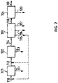
- FIG 2 is a schematic view of a compression and purification unit which could be used as unit 7 in Figure 1 .
- Flue gas stream 110 (corresponding to stream 24 of Figure 1 ) enters a low pressure pretreatment unit 101 where it is prepared for compression unit 102.
- This unit could include, for example, among other steps:
- Waste stream(s) 111 could include condensed water, dust and dissolved species like H 2 SO 4 , HNO 3 , Na 2 SO 4 , CaSO 4 , Na 2 CO 3 , and CaCO.
- Compression unit 102 compresses stream 112 from a pressure close to atmospheric pressure to a high pressure typically between 15 and 60 bar abs, preferably around 30 bar abs. This compression could be done in several stages with intermediate cooling. In this case, some condensate(s) 113 could be produced. Such condensate(s) 113 typically includes HNO 3 formed from reaction of NO 2 and water. Heat of compression may be usefully recovered in the intermediate cooling step, for example, in preheating boiler feed water. Hot stream 114 leaves the compression unit 102 and enters a high pressure pretreatment unit 103.
- the high pressure pretreatment unit 103 includes at least:
- the high pressure pretreatment unit 103 could also include, but is not limited to:
- Effluents from unit 103 include gaseous stream 115 (the regeneration stream of the drying step) and may include liquid stream(s) 116/117 (from the cooling step and/or the high pressure washing column).
- the stream 114 may contain NO 2 . In this case, it is sometimes preferable to remove the NO 2 by adsorption upstream of the unit 104. In this case, the stream 114 may be treated by adsorption and the regeneration gas used to regenerate the adsorbent is removed having a content enriched in NO 2 with respect to that of stream 114.
- the gaseous stream 115 may optionally be recycled at least in part upstream of the compression unit 102, upstream of the pretreatment unit 101 or to the boiler 1 of the combustion unit.
- Unit 104 is a low temperature purification unit.
- low temperature means a minimum temperature in the process cycle for the purification of the flue gas below 0° C. and preferably below -20° C. as close as possible to the triple point temperature of pure CO 2 at -56.6° C.
- stream 118 is cooled down and partially condensed in one (or several steps).
- One (or several) liquid phase stream(s) enriched in CO 2 is (are) recovered, expanded and vaporized in order to have a product enriched in CO 2 119.
- Such gaseous CO2 product may be used on-site.
- the recovered liquid phase stream(s) enriched in CO 2 may be maintained in liquid form and the pressure and temperature adjusted according to known techniques to provide a liquid product CO 2 stream suitable for storage, on-site consumption, or transport by tube trailer.
- the pressure and temperature of the recovered liquid phase stream(s) enriched in CO 2 may be adjusted according to known techniques to provide a supercritical product CO 2 stream suitable for injection into a pipeline or sequestered in a geologic formation.
- One (or several) incondensible high pressure stream(s) 120 is (are) recovered and could be expanded in an expander.
- Unit 104 includes a rectifying distillation column that separates a NO 2 and CO 2 -containing feed fluid into a CO 2 -enriched gaseous stream and a NO 2 -enriched liquid stream (relative to the concentrations of NO 2 and CO 2 in the feed fluid).
- the feed fluid can consist of stream 118 or may be derived from stream 118 after further treatment of stream 118.
- Unit 104 also includes a fluid separation membrane (operated under pervaporative conditions) that separates the NO 2 -enriched liquid stream from the rectifying column into a NO 2 -enriched gaseous permeate stream and a liquid non-permeate stream. The liquid non-permeate stream is recycled to the rectifying column.
- a fluid separation membrane operted under pervaporative conditions
- Unit 104 also includes phase separator that expands the CO 2 -enriched gaseous stream from the rectifying column and separates it into a gaseous stream (for eventual venting) and a liquid stream for feeding to a stripping distillation column (which also receives a stripping fluid derived from vaporization of at least a portion of the liquid non-permeate stream).
- the distillation column strips the incondensable components (O 2 , N 2 , and Ar) from the combined contents of the stripping fluid and the liquid stream (from the phase separator) into a gaseous stream and the liquid phase stream(s) enriched in CO 2 .
- the gaseous stream from the stripping column may be combined with the feed fluid fed to the rectifying column.
- CO 2 enriched product 119 may be further treated to provide it in whichever forms (gaseous, liquid, supercritical, solid) and pressure/temperature desired.
- CO2 enriched product 119 may be further compressed condensed and then further compressed with a pump in order to be delivered at high pressure (typically 100 to 200 bar abs) for injection into a pipeline leading to the sequestration site.
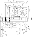
- Figure 3 shows a low temperature purification unit that could be used as unit 104 in Figure 2 . At least one process according to the invention operates within such a unit.
- Stream 118 comprising flue gas at around 30 bar and at a temperature of between 15° C and 43° C contains mainly carbon dioxide but also includes lesser amounts of NO 2 , oxygen, argon and nitrogen.
- the actual amount of NOx will vary over time depending upon how much NOx has already been adsorbed in the driers. Typically, the inlet NOx will vary between 0ppm and 500ppm. The actual amount of NOx will also depend upon the type of burner producing the flue gas.
- Stream 118 may be produced by unit 103 already at the desired pressure conditions or it may be brought up to the desired pressure level using optional compressor 124.
- Compressed flue gas stream 127 is alternatingly directed to one of two driers 129, 131. While one of the driers 129, 131 is being operated to dry stream 127, the other of the driers is regenerated.
- Dried, compressed flue gas stream 133 is cooled and at least partially condensed at multi-fluid heat exchanger 135.
- the liquid or biphasic flue gas stream 137 is fed to rectifying (also known as De-NOx) column 139 as reflux and separated into a NO 2 -enriched liquid stream 141 and a CO 2 -enriched gaseous stream 143.
- the pressure in the De NOx column is typically about 25 bar abs where the inlet gas temperature is about -19°C.
- the NO 2 -enriched liquid stream 141 is fed to a feed gas side of a pervaporative separation membrane 147.
- the membrane 147 includes a separation layer that is comprised of a material that selectively permeates NO 2 (and SO 2 , if present) over CO 2 so as to provide a NO 2 -enriched permeate and a CO 2 -enriched non-permeate.
- An optional sweep gas 145 fed to a permeation side (opposite that of the feed gas side) of membrane 147 will enhance permeation of the NO 2 from stream 141 across the membrane 147 from the feed gas side to the permeation side by lowering its partial pressure on the permeate side.
- the combined sweep gas 145 and NO 2 -enriched permeate is withdrawn from membrane 147 as stream 149.
- the CO 2 -enriched non-permeate withdrawn from membrane 147 as liquid stream 151 is pressurized with pump 153.
- the pressurized liquid stream 155 is combined with stream 192 and recycled back to rectifying column 139.
- Gaseous stream 143 containing between about 1-5ppm NO 2 and about 98% CO 2 , is cooled and at least partially condensed at heat exchanger 135 to provide a cool biphasic stream 161.
- Biphasic stream 161 is then fed to a phase separator 163 to provide a N 2 , O 2 , and Ar-enriched gaseous stream 165 and a CO 2 -enriched liquid stream 167.
- Stream 165 is warmed at heat exchanger 135 and the warmed stream 169 further warmed at heater or heat exchanger 171. Twice-warmed stream 171 is used to regenerate the drier 129, 131 being operated in regeneration mode and then subsequently warmed at heat exchanger 177 in order enhance the available expansion energy recovered at expander 179. Downstream of expander 179, it is warmed at heat exchanger 135 and the warmed, expanded stream 120 vented.
- the pressure of the CO 2 -enriched liquid stream 167 is decreased at expansion valve and fed as reflux to stripping column 186.
- Column 186 under a pressure around 15 bar and a temperature between -27°C and-50°C, operates to remove the incondensible components (N 2 , O 2 , and Ar) in the form of a CO 2 -depleted gaseous stream 187 from the top of column 186.
- Some of the cold energy of stream 187 is recovered at heat exchanger 135, thereby providing warmed stream 189 which is combined with flue gas stream 118 at the suction inlet of compressor 124.
- a carbon dioxide liquid stream 191 is also removed from the bottom of column 186 and split into stream 192, stream 194, and stream 196.
- Stream 192 is combined with the liquid non-permeate stream 155 to provide stream 157 which is fed to the rectifying column 139.
- the pressure of stream 194 is reduced at expansion valve 193 to provide a cooler, biphasic (liquid/gaseous CO 2 ) stream 195.
- Latent heat in stream 195 is recovered at heat exchanger 135 through vaporization of the remaining liquid phase of biphasic stream 195 to provide gaseous stream 197.
- the CO 2 in stream 196 is warmed in two portions at heat exchanger 135 to different degrees.
- Resultant stream 198 is superheated while stream 200 remains at its dewpoint and is fed to stripping column 186 for providing the necessary heat to the column.
- Stream 197 and stream 198 are then combined at the suction inlet of compressor 199, compressed at compressor 199 and cooled at heat exchanger 201 to a level above the critical pressure of CO 2 .
- the pressure of the cooled, compressed stream is then raised above the critical pressure of CO 2 to provide supercritical CO 2 -enriched product stream 119 useful for injection into a pipeline.
- the CO 2 -enriched product 119 may instead be provided in liquid form for storage, on-site consumption, and/or transport by tube trailer.
- the liquid CO 2 stream 191 need not be fed to expansion valve 193 or passed through heat exchanger 135.
- the pressure and/or temperature of liquid CO 2 stream 191 may be adjusted according to techniques well-known in the art to provide any desired pressure and temperature for a liquid CO 2 -enriched product 119.
- the membrane 147 includes a perm-selective separation layer that is primarily responsible for the separation of NO 2 (along with SO 2 if present) and CO 2 .
- the membrane 147 may be made entirely of the polymeric material of the separation layer.
- the membrane 147 may instead have a composite structure where the separation layer is supported by a support layer whose purpose is to provide mechanical strength.
- the material of the support layer may be any material known to those skilled in the art of fluid membrane separation as having relatively high flux and sufficiently desirable mechanical strength.
- the membrane 147 may have any configuration known to those skilled in the art of fluid separation membranes, including spirally-wound sheets and hollow fibers.
- the membrane 147 operates on a solubility selectivity principle. Solubility is usually correlated with molecular parameters such as the Lennard-Jones affinity constant or the critical temperature. Since the critical temperatures of NO 2 and SO 2 are above 157 °C and the critical temperature of CO 2 is only 30.98 °C, we believe that NO 2 and SO 2 are expected to exhibit high permeability through polymers with flexible main chains and having polar affinity.
- polysiloxane copolyethers which are cross-linked
- polyurethane-polyether block copolymers poly(urea)-poly(ether) block copolymers
- poly(ester)-poly(ether) block copolymers poly(amide)-poly(ether) block copolymers.
- polysiloxane copolyether comprises polysiloxane copolyether comprises a polymeric chain comprising repeating units of the molecular segment of formula (1), a terminal molecular segment -O-W bonded to a silicon atom of one end of the chain where O is an oxygen atom, and a terminal molecular segment -W bonded to an oxygen atom of the other end of the chain:
- Each W is selected from the group consisting of a -Si(CH 3 ) 3 group, the molecular segment of formula (2), the molecular segment of formula (3), and the molecular segment of formula (4); -(CH 2 ) p -X-OH (2) -(CH 2 ) p -NH-(CH 2 ) q -NH 2 (3)
- Each X comprises b repeating units of the molecular segment of formula (5) and c repeating units of the molecular segment of formula (6): -(O-CH 2 -CH 2 )- (5)
- Each R is individually selected from the group consisting of a phenyl group, a C 1 -C 6 alkyl group, the molecular segment of formula (2), the molecular segment of formula (3), and the molecular segment of formula (4);
- each W is a -Si(CH 3 ) 3 group or the molecular segment of formula (3), then at least some R's are the molecular segment of formula (2) or the molecular segment of formula (4).
- each R is either a phenyl group or a C 1 -C 6 alkyl group, then each W is either the molecular segment of formula (2) or the molecular segment of formula (4).
- the number of repeating units where R is a C 1 -C 6 alkyl group is 1-2000.
- the ratio of polyether segments to polysiloxane segments may vary.
- W is -Si(CH 3 ) 3 group
- cross-linking sites are present in the middle of the chain and the ratio of the number of molecular segments that are of either formulae (5) or (6) to the number of silicon atoms in the chain ranges from about 0.05 to about 6.0.
- each R is either a phenyl group or a C 1 -C 6 alkyl group
- cross-linking sites are present at each end of the chain and the ratio of the number of molecular segments that are of either formulae (5) or (6) to the number of silicon atoms in the chain ranges from about 0.05 to about 0.33.
- a greater content of siloxane-based repeating units is desired for providing greater robustness.
- a potential cross-linking site may be wherever either W or R is the molecular segment of formulae (2), (3), or (4).
- the type of linkage formed at the cross-linked site will depend upon the W or R in question and the type of cross-linking agent or cross-linking promoter.
- a urethane linkage may be formed using a monomeric diisocyanate, a monomeric triisocyanate or polymeric isocyanate cross-linking agent.
- a urea linkage may be formed using a monomeric diisocyanate, a monomeric triisocyanate or polymeric isocyanate cross-linking agent.
- an amide linkage may instead be formed using a di-acyl chloride substituted aromatic cross-linking agent, or a tri-acyl chloride substituted aromatic cross-linking agent.
- the copolymer may be cross-linked using a free radical cross-linking promoter, such as an azo or peroxide free radical initiator.
- Non-limiting examples of suitable monomeric diisocyanate, monomeric triisocyanate or polymeric isocyanate cross-linking agents are toluene diisocyanate (TDI) commercially available from a wide variety of sources or cyanate-functionalized siloxanes commercially available from Siltech.
- suitable di-acyl chloride substituted aromatic cross-linking agents and tri-acyl chloride substituted aromatic cross-linking agents include 1, 3-benzenedicarbonyl dichloride, 1,4-benzenedicarbonlyl dichloride, and 1,3,5-benzenetricarbonyl trichloride.
- the cross-linked polysiloxane copolyether may optionally be cross-linked together with one or more silicone elastomers.
- the silicone elastomer may be derived from a first silicone polymer having a first reactive functional group (such as a vinylsiloxane unit) and a crosslinking agent having a second reactive functional group (such as a hydrogensiloxane unit).
- Suitable silicone elastomers may be commercially obtained from Momentive under trade name RTV615 and from Dow Corning under trade name Sylgard 184,182, or 186.
- Particularly suitable types of polysiloxane copolyethers may be commercially obtained from Siltech under the trade names D-208, Di-2510, Di-5018F, Di1010, and J-1015-O.
- the polyurethane-polyether block copolymers are produced by reacting at least one polyether glycol with either an aromatic or aliphatic diisocyanate followed by reaction with at least one aliphatic diol (to form a polyurethane-polyether) or with a at least one aliphatic diamine (to form a polyurea-polyether) in the presence of a catalyst, such as organotin compounds, such as dibutyltindilaurate, but other catalysts known to one skilled in the art may be used.
- a catalyst such as organotin compounds, such as dibutyltindilaurate, but other catalysts known to one skilled in the art may be used.
- the resulting polymers contain the soft segments of formula (I s ) comprising polyether and the hard segments of formula (I h ) comprising polyurethane or polyurea.
- the resultant polyurethane-polyether or polyurea-polyether block copolymers are represented by the repeating units of formulas (I s ) and (I h ):
- R i of formulas (I s ) and (I h ) is an aliphatic or aromatic radical of at least about 2-18 carbon atoms.
- (PE) is a polyether segment having a number average molecular weight, M n (which is essentially equivalent to M n of the repeating formula (I s )), ranging from about 600 to 8000, and preferably about 1000 to 4000.
- R a of (I h ) is a linear or branched aliphatic radical of at least about 2-18 carbon atoms; and, X is an oxygen atom or -NH-. If X is oxygen, the block copolymer is a polyurethane-polyether, and if X is -NH-, the block copolymer is a polyurea-polyether.
- the number of carbon atoms in the repeating units may vary and there may be varieties and combinations of numbers of carbon atoms therein.
- the number average molecular weight of the repeating formula (I h ) is preferably in the range of about 200 to 3000, and more preferably about 200-1000.
- Ri is linear -(CH 2 ) 6 -, or a moiety of composition selected from the group primarily comprising formula (S), formula (T), formula (U), or (V) below, and a combination or mixtures thereof.
- S formula
- T formula
- U formula
- V formula
- These structures correspond to 1,6-hexanediisocyanate, tolylene-2,6-diisocyanate, tolylene-2,4-diisocyanate, 1,3-xylylenediisocyanate, and 4,4'-methylenebis (phenylisocyanate), respectively.
- the polyether segment, (PE) is derived preferably from a polyether glycol of number average molecular weight of about 600-8000, and more preferably about 1000-4000, and preferably an oxygen/carbon ratio of about 0.2-0.5.
- Preferred polyether glycols are hydroxyl terminated polyethylene glycol, hydroxyl terminated 1,2-polypropylene glycol, and hydroxyl terminated 1,4-polybutylene glycol, although other glycols known or used by one skilled in the art may be used.
- the hard segment of the polyurethane-polyether or polyurea-polyether block copolymer is derived from the reaction of residual aliphatic or aromatic diisocyanate end groups or monomer with either at least one aliphatic diol or at least one aliphatic diamine.
- Preferred diols or diamines contain at least about 2-18 carbon atoms and can be linear or branched. Most preferred are diols or diamines containing at least about 2-6 carbon atoms.
- Typical diols and diamines are ethylene glycol, 1,3-propanediol, 1,2-propanediol, 1,4-butanediol, 1,6-hexanediol, 1,2-diaminoethane, 1,4-diaminobutane, 1,5-diaminopentane, 1,5-diaminohexane, 1,6-diaminohexane, and dl-serine (3-amino-2-hydroxypropionic acid), although other diols and diamines known or used by one skilled in the art may be used.
- the polyurethane-polyether or polyurea-polyether block copolymers exhibit a number average molecular weight in the range from about 23,000 to 400,000 and preferably about 50,000-280,000. As shown from the variety of combinations of components, a wide range and variety of types of polyurethane-polyether and polyurea-polyether block copolymers are contemplated and disclosed herein.
- the soft segment comprises about 50-90 weight percent of the block copolymer weight, and more typically, about 60-85 percent.
- the polyester-polyether block copolymers are produced by reacting at least one hydroxyl terminated polyether glycol, an excess of at least one aliphatic diol, and at least one dicarboxylic ester of an aromatic or aliphatic diacid in the presence of a catalyst.
- the resulting polymers contain the soft segments of formula (II s ) comprising polyether and the hard segments of formula (II h ) comprising polyester: R a of (II s ) and (II h ) is an aliphatic or aromatic radical of about at least 2-18 carbon atoms.
- (PE) of (II s ) is a polyether segment having a number average molecular weight, M n (which is essentially equivalent to M n of the repeating formula (II s )), ranging from about 600 to 8000, and preferably about 1000 to 4000.
- R d of (II h ) is at least one linear or branched aliphatic radical of about at least 2-18 carbon atoms. Within the polyester-polyether block copolymer, the number of carbon atoms in the repeating units may vary and there may be varieties and combinations of numbers of carbon atoms therein.
- the average molecular weight of the repeating formula (II h ) is preferably in the range of about 200 to 3000, and more preferably about 200-1000.
- R a is a moiety of composition selected from the group consisting or comprising formulas (S), (T), (U), (V), (W), (X), or (Y) below, or a combination or mixture thereof:
- formula (Y) is present or included, the -Z- in formula (Y) is a moiety selected from the group comprising or consisting of formulas (A), (B), (C), or (D), below, or a mixture or combination thereof: -CH 2 - (A) -O- (B)
- the polyether segment, (PE), of the polyester-polyether block copolymer is derived preferably from a polyether glycol of number average molecular weight of about 600-8000, and more preferably about 1000-4000, and preferably an oxygen/carbon ratio of about 0.2-0.5.
- Preferred polyether glycols are hydroxyl terminated polyethylene glycol, hydroxyl terminated 1,2-polypropylene glycol, and hydroxyl terminated 1,4-polybutylene glycol, although other glycols known or used by one skilled in the art may be used.
- the hard segment of the block copolymer is derived from the condensation polymerization of at least one ester of an aromatic or aliphatic diacid with at least one aliphatic diol.
- R d of formula (I h) is a derivative of the aliphatic diol.
- Preferred diols contain at least about 2-18 carbon atoms and can be linear and/or branched. Most preferred are diols containing between about 2-6 carbon atoms.
- Typical diols are ethylene glycol, 1,3-propanediol, 1,2-propanediol, 1,4-butanediol, and 1,6-hexanediol, although other diols known or used by one skilled in the art may be used.
- the polymers of this invention exhibit a number average molecular weight in the range from about 23,000 to 400,000 and preferably about 50,000-280,000. As shown from the variety of combinations of components, a variety of types of polyester-polyether block copolymers are contemplated and disclosed herein.
- the soft segment of the polyester-polyether block copolymer comprises about 50-90 weight percent of the copolymer weight, and more typically, about 60-85 percent.
- the polyamide-polyether block copolymers comprise repeating units of the moiety of formula III: where PA is a saturated aliphatic polyamide segment and PE is a polyether segment.
- PA is a saturated aliphatic polyamide segment
- PE is a polyether segment.
- the saturated aliphatic polyamide segment is either:
- polyether segment is either:
- polyamide-polyether block copolymers are commercially available from Arkema under the tradename PEBAX. These are obtained by polycondensation of a carboxylic acid polyamide (PA6, PA11, PA12) with an alcohol terminated polyether such as poly(tetramethyleneglycol) (PTMG) or polyethyleneglycol (PEG).
- PEBAX poly(tetramethyleneglycol)
- PTMG poly(tetramethyleneglycol)
- PEG polyethyleneglycol
- “Comprising” in a claim is an open transitional term which means the subsequently identified claim elements are a nonexclusive listing i.e. anything else may be additionally included and remain within the scope of “comprising.”
- “Comprising” is defined herein as necessarily encompassing the more limited transitional terms “consisting essentially of” and “consisting of”; “comprising” may therefore be replaced by “consisting essentially of” or “consisting of” and remain within the expressly defined scope of “comprising”.
- Providing in a claim is defined to mean furnishing, supplying, making available, or preparing something. The step may be performed by any actor in the absence of express language in the claim to the contrary.
- Optional or optionally means that the subsequently described event or circumstances may or may not occur.
- the description includes instances where the event or circumstance occurs and instances where it does not occur.
- Ranges may be expressed herein as from about one particular value, and/or to about another particular value. When such a range is expressed, it is to be understood that another embodiment is from the one particular value and/or to the other particular value, along with all combinations within said range.
Landscapes
- Chemical & Material Sciences (AREA)
- Chemical Kinetics & Catalysis (AREA)
- Engineering & Computer Science (AREA)
- Water Supply & Treatment (AREA)
- General Chemical & Material Sciences (AREA)
- Analytical Chemistry (AREA)
- Oil, Petroleum & Natural Gas (AREA)
- Organic Chemistry (AREA)
- Mechanical Engineering (AREA)
- Thermal Sciences (AREA)
- General Engineering & Computer Science (AREA)
- Physics & Mathematics (AREA)
- Inorganic Chemistry (AREA)
- Separation Using Semi-Permeable Membranes (AREA)
- Carbon And Carbon Compounds (AREA)
Claims (16)
- Procédé pour séparer du NO2 d'un fluide contenant du CO2 et du NO2, ledit procédé comprenant les étapes suivantes :l'acheminement d'un fluide comprenant du CO2, du NO2, et au moins l'un parmi de l'oxygène, de l'argon, et de l'azote, jusqu'à une colonne de distillation de rectification (139) ;l'extraction d'un premier flux gazeux (143) à partir de la colonne de rectification qui est enrichi en CO2 et pauvre en NO2 par rapport au fluide comprenant du CO2, du NO2, et au moins l'un parmi de l'oxygène, de l'argon, et de l'azote ;l'extraction d'un flux liquide (141) à partir de la colonne de rectification qui est enrichi en NO2 par rapport au fluide comprenant du CO2, du NO2, et au moins l'un parmi de l'oxygène, de l'argon, et de l'azote ; caractérisé en ce qu'il comprendl'acheminement du flux liquide enrichi en NO2 jusqu'à une membrane de séparation de fluide (147) ;l'extraction d'un deuxième flux gazeux (149) comprenant un gaz perméat à partir de la membrane qui est enrichi en NO2 et pauvre en CO2 par rapport au flux liquide acheminé jusqu'à la membrane ;l'extraction d'un flux liquide non perméat (151) à partir de la membrane qui est pauvre en NO2 et enrichi en CO2 par rapport au flux liquide acheminé jusqu'à la membrane ; etle recyclage du flux liquide non perméat dans la colonne de rectification.
- Procédé selon la revendication 1, dans lequel le fluide comprenant du CO2, du NO2, et au moins l'un parmi de l'oxygène, de l'argon, et de l'azote est produit par compression d'un gaz de fumée dans un compresseur (124) suivi par le séchage et la condensation au moins partielle du gaz de fumée comprimé dans un échangeur de chaleur (135).
- Procédé selon la revendication 2, comprenant en outre les étapes suivantes :la condensation au moins partielle du premier flux gazeux dans un échangeur de chaleur (153) ;la séparation du flux au moins partiellement condensé dans un séparateur de phase (163) pour produire un troisième flux gazeux (163) enrichi en au moins l'un parmi de l'oxygène, de l'argon, et de l'azote par rapport au premier flux gazeux et un flux liquide (167) enrichi en CO2 par rapport au premier flux gazeux ;l'acheminement du flux liquide enrichi en CO2 jusqu'à une colonne de stripping (186) ;l'acheminement d'un quatrième flux gazeux (187) extrait à partir de la colonne de stripping jusqu'à une entrée d'aspiration du compresseur ; etl'extraction d'un flux de CO2 du type produit liquide (191) à partir de la colonne de stripping.
- Procédé selon la revendication 3, comprenant en outre les étapes suivantes :l'expansion du flux de CO2 du type produit liquide (191) pour fournir un flux de CO2 du type produit biphasique ;la vaporisation de tout élément liquide dans un flux de CO2 de type produit biphasique dans un échangeur de chaleur (135) pour fournir un flux de CO2 du type produit totalement gazeux ; etla compression et le refroidissement du flux de CO2 du type produit totalement gazeux pour fournir un flux de CO2 du type produit supercritique (205).
- Procédé selon la revendication 1, comprenant en outre l'étape d'acheminement d'un gaz d'entraînement (145) jusqu'à la membrane de séparation de fluide (147), dans lequel le deuxième flux gazeux (149) comprend en outre le gaz d'entraînement.
- Procédé selon la revendication 1, comprenant en outre les étapes d'acheminement du deuxième flux gazeux (149) jusqu'à une colonne de lavage pour dissoudre au moins une partie du NO2 présent dans le deuxième flux gazeux et former de l'acide nitrique.
- Procédé selon la revendication 2, comprenant en outre l'étape de combustion de carburant (14) avec un comburant (10) dans une chaudière (71) pour produire le gaz résiduaire, dans lequel le gaz résiduaire (19) présente une teneur en NOx supérieure à 300 ppm.
- Procédé selon la revendication 1, dans lequel une couche de séparation de la membrane de séparation de fluide (147) comprend un matériau choisi parmi le groupe constitué de ce qui suit : un copolyéther de polysiloxane réticulé, un copolymère bloc polyuréthane-polyéther, un copolymère bloc poly(urée)-poly(éther), un copolymère bloc poly(ester)-poly(éther), et un copolymère bloc poly(amide)-poly(éther).
- Appareil pour séparer du NO2 d'un fluide contenant du CO2 et du NO2, comprenant :une source d'un fluide comprenant du NO2 et du CO2 (71, 124) ;une colonne de distillation de rectification (139) recevant le fluide source ;une membrane de séparation de fluide (147) qui reçoit un flux liquide (141) à partir de la colonne de rectification et produit un flux non perméat liquide (151, 157) et un flux perméat gazeux (149) ;une pompe (153) acheminant, jusqu'à la colonne de rectification, le liquide non perméat à partir de la membrane ;un échangeur de chaleur (135) condensant au moins partiellement un flux gazeux (143) à partir de la colonne de rectification etun séparateur de phase (163) recevant le flux au moins partiellement condensé à partir de l'échangeur de chaleur et produisant un flux gazeux (165) comprenant une majorité de N2, d'O2, et/ou d'Ar et un flux liquide (167) comprenant une majorité de CO2 ;caractérisé en ce qu'il comprendune colonne de distillation de stripping (186) recevant le flux liquide comprenant une majorité de CO2 provenant du séparateur de phase, la colonne de stripping étant adaptée et configurée pour séparer les contenus du flux liquide comprenant une majorité de CO2 en un flux gazeux (187) et en un flux de produit CO2 liquide (191).
- Appareil selon la revendication 9, comprenant en outre un compresseur (124) et une unité de séchage (131) adaptés et configurés pour compresser et sécher le fluide source, dans lequel l'échangeur de chaleur (135) est également adapté et configuré pour condenser au moins partiellement le fluide source comprimé et séché avant d'être acheminé jusqu'à la colonne de rectification.
- Appareil selon la revendication 10, dans lequel la source de fluide est une chaudière (71) adaptée et configurée pour produire un gaz de fumée (19) et le gaz de fumée est le fluide comprenant du NO2 et du CO2.
- Appareil selon la revendication 10, dans lequel le compresseur (124) reçoit également le flux gazeux (187) à partir de la colonne de stripping (186).
- Appareil selon la revendication 10, comprenant en outre un compresseur (199) et un dispositif de refroidissement (201) qui compriment et refroidissent le flux de produit CO2 totalement gazeux pour fournir un flux de CO2 du type produit supercritique.
- Appareil selon la revendication 9, comprenant en outre une source de gaz d'entraînement (145), la membrane (147) recevant également le gaz d'entraînement sur un côté perméat de la membrane.
- Appareil selon la revendication 9, comprenant en outre une colonne de lavage recevant le flux de perméat gazeux (149) et dissolvant au moins une partie du NO2 présent dans le flux de perméat gazeux pour former de l'acide nitrique.
- Appareil selon la revendication 9, dans lequel la membrane (147) comporte une couche de séparation comprenant un matériau choisi parmi le groupe constitué de ce qui suit : un copolyéther de polysiloxane réticulé, un copolymère bloc polyuréthane-polyéther, un copolymère bloc poly(urée)-poly(éther), un copolymère bloc poly(ester)-poly(éther), et un copolymère bloc poly(amide)-poly(éther).
Priority Applications (1)
| Application Number | Priority Date | Filing Date | Title |
|---|---|---|---|
| PL15716304T PL3145606T3 (pl) | 2014-03-28 | 2015-03-27 | Sposób i urządzenie do oddzielania NO<sub>2</sub> od płynu zawierającego CO<sub>2</sub> i NO<sub>2</sub> |
Applications Claiming Priority (3)
| Application Number | Priority Date | Filing Date | Title |
|---|---|---|---|
| US201461971840P | 2014-03-28 | 2014-03-28 | |
| US14/265,710 US9458022B2 (en) | 2014-03-28 | 2014-04-30 | Process and apparatus for separating NO2 from a CO2 and NO2—containing fluid |
| PCT/US2015/022999 WO2015148927A1 (fr) | 2014-03-28 | 2015-03-27 | Procédé et appareil de séparation de no2 d'un fluide contenant du co2 et du no2 |
Publications (2)
| Publication Number | Publication Date |
|---|---|
| EP3145606A1 EP3145606A1 (fr) | 2017-03-29 |
| EP3145606B1 true EP3145606B1 (fr) | 2018-08-01 |
Family
ID=54189805
Family Applications (1)
| Application Number | Title | Priority Date | Filing Date |
|---|---|---|---|
| EP15716304.9A Active EP3145606B1 (fr) | 2014-03-28 | 2015-03-27 | Procédé et appareil de séparation de no2 d'un fluide contenant du co2 et du no2 |
Country Status (5)
| Country | Link |
|---|---|
| US (2) | US9458022B2 (fr) |
| EP (1) | EP3145606B1 (fr) |
| CN (1) | CN106132495B (fr) |
| PL (1) | PL3145606T3 (fr) |
| WO (1) | WO2015148927A1 (fr) |
Families Citing this family (21)
| Publication number | Priority date | Publication date | Assignee | Title |
|---|---|---|---|---|
| US9458022B2 (en) * | 2014-03-28 | 2016-10-04 | L'Air Liquide Société Anonyme Pour L'Étude Et L'Exploitation Des Procedes Georges Claude | Process and apparatus for separating NO2 from a CO2 and NO2—containing fluid |
| FR3045403B1 (fr) * | 2015-12-18 | 2022-02-11 | Electricite De France | Systeme de regeneration membranaire d'un solvant de captage de gaz acide |
| CN106839651A (zh) * | 2017-03-27 | 2017-06-13 | 四川华亿石油天然气工程有限公司 | 一种从真空烘箱尾气中回收氮气的系统及工艺 |
| CN107029546A (zh) * | 2017-04-20 | 2017-08-11 | 北京国电龙源环保工程有限公司 | 基于碱性吸收剂细小颗粒的so3脱除系统及其脱除方法 |
| FR3070016B1 (fr) * | 2017-08-10 | 2019-08-23 | L'air Liquide, Societe Anonyme Pour L'etude Et L'exploitation Des Procedes Georges Claude | Procede et installation de purification d'un flux gazeux d'alimentation comprenant au moins 90% de co2 |
| CN107485981B (zh) * | 2017-09-05 | 2020-05-12 | 北京科技大学 | 一种烟气脱硝装置和方法 |
| CN107855210B (zh) * | 2017-12-08 | 2023-04-25 | 西安热工研究院有限公司 | 超临界机组中速磨煤机出口温度节能优化控制系统及方法 |
| CN109289486B (zh) * | 2018-11-02 | 2021-06-11 | 辽宁新瑞碳材料科技有限公司 | 一种高温尾气中氮气的分离回收方法 |
| CN109289342B (zh) * | 2018-11-02 | 2021-06-11 | 辽宁新瑞碳材料科技有限公司 | 一种分离回收高温炉尾气的系统和方法 |
| CN109289449B (zh) * | 2018-11-02 | 2021-06-11 | 辽宁新瑞碳材料科技有限公司 | 一种高温炉尾气的回收方法 |
| WO2020104004A1 (fr) * | 2018-11-19 | 2020-05-28 | Nov Process & Flow Technologies As | Système de récupération d'inhibiteur d'hydrates |
| US11149634B2 (en) * | 2019-03-01 | 2021-10-19 | Richard Alan Callahan | Turbine powered electricity generation |
| US11149636B2 (en) * | 2019-03-01 | 2021-10-19 | Richard Alan Callahan | Turbine powered electricity generation |
| US11071947B2 (en) | 2019-10-30 | 2021-07-27 | W. L. Gore & Associates, Inc. | Catalytic efficiency of flue gas filtration |
| US10940471B1 (en) * | 2019-10-30 | 2021-03-09 | W. L. Gore & Associates, Inc. | Catalytic efficiency of flue gas filtration |
| CN113477033B (zh) * | 2021-07-20 | 2023-03-14 | 金浦新材料股份有限公司 | 一种可自乳化有机硅脱碳溶剂 |
| FR3135212B1 (fr) | 2022-05-09 | 2024-03-22 | Air Liquide | Procédé et appareil de purification d’un flux gazeux contenant au moins un oxyde d’azote |
| EP4520416A1 (fr) | 2023-09-11 | 2025-03-12 | L'air Liquide, Societe Anonyme Pour L'etude Et L'exploitation Des Procedes Georges Claude | Procédé et appareil pour séparer du co2 d'un flux d'alimentation contenant du co2, au moins un composant léger et au moins un composant lourd |
| US20250262584A1 (en) * | 2024-02-16 | 2025-08-21 | Uop Llc | NOx REMOVAL FOR CRYOGENIC CARBON CAPTURE FROM FLUE GAS |
| FR3160595B1 (fr) | 2024-03-26 | 2026-02-20 | Air Liquide | Procédé et appareil de séparation d’un mélange de CO2 et de NOx par condensation partielle |
| FR3161576A1 (fr) | 2024-04-26 | 2025-10-31 | L'air Liquide, Societe Anonyme Pour L'etude Et L'exploitation Des Procedes Georges Claude | Procédé et appareil de séparation d’un mélange contenant du CO2, au moins un composant plus léger que le CO2 et du mercure |
Family Cites Families (52)
| Publication number | Priority date | Publication date | Assignee | Title |
|---|---|---|---|---|
| US3303105A (en) * | 1963-03-25 | 1967-02-07 | Gen Electric | Diffusion of water vapor through slicone rubber |
| US3739553A (en) * | 1971-06-14 | 1973-06-19 | H Aine | Exhaust emission control means for internal combustion apparatus |
| US4001279A (en) * | 1973-03-29 | 1977-01-04 | The Regents Of The University Of California | Asymmetric macrocycles containing oxygen and binaphthyl ring members |
| US4425313A (en) * | 1976-08-16 | 1984-01-10 | Cooper Hal B H | Removal and recovery of nitrogen and sulfur oxides from gaseous mixtures containing them |
| US4073089A (en) * | 1976-09-27 | 1978-02-14 | Canadian Patents And Development Limited | Utilization of exhaust gases for plant growth |
| US4272437A (en) * | 1978-12-18 | 1981-06-09 | Bristol-Myers Company | Antibacterial agents, and 4-thio azetidinone intermediates |
| IN154274B (fr) * | 1980-09-02 | 1984-10-13 | Ube Industries | |
| DE3037736C2 (de) * | 1980-10-06 | 1984-01-26 | Achim Dipl.-Ing. 6650 Homburg Ballweg | Verfahren zur Entwässerung von Gemischen aus organischen Flüssigkeiten und Wasser |
| US4717406A (en) | 1986-07-07 | 1988-01-05 | Liquid Air Corporation | Cryogenic liquified gas purification method and apparatus |
| US4963165A (en) | 1987-04-27 | 1990-10-16 | Membrane Technology & Research, Inc. | Composite membrane, method of preparation and use |
| US4774365A (en) * | 1987-11-25 | 1988-09-27 | Air Products And Chemicals, Inc. | Pervaporation process for separating alcohols from ethers |
| US5352272A (en) * | 1991-01-30 | 1994-10-04 | The Dow Chemical Company | Gas separations utilizing glassy polymer membranes at sub-ambient temperatures |
| US5080698A (en) * | 1991-04-25 | 1992-01-14 | E. I. Du Pont De Nemours And Company | Aromatic polyethers containing cyano groups for gas separation |
| NL9300322A (nl) * | 1992-02-24 | 1993-09-16 | Shell Int Research | Werkwijze voor het behandelen van zuur vloeibaar gemaakt petroleumgas. |
| JPH06287153A (ja) * | 1993-04-02 | 1994-10-11 | Mitsubishi Petrochem Co Ltd | 無水エタノールの製造方法 |
| FR2711986B1 (fr) * | 1993-11-05 | 1996-02-02 | Inst Francais Du Petrole | Procédé de séparation des composés oxygénés d'hydrocarbures, combinant une distillation et une perméation et son utilisation en éthérification. |
| FR2717798B1 (fr) | 1994-03-28 | 1996-05-10 | Inst Francais Du Petrole | Procédé de purification de l'éthyl tertio butyl éther combinant un procédé à membrane et une distillation. |
| US5585527A (en) * | 1994-10-31 | 1996-12-17 | Uop | Continuous distillation and membrane process |
| US5634354A (en) * | 1996-05-08 | 1997-06-03 | Air Products And Chemicals, Inc. | Olefin recovery from olefin-hydrogen mixtures |
| US6257018B1 (en) * | 1999-06-28 | 2001-07-10 | Praxair Technology, Inc. | PFC recovery using condensation |
| US6843829B2 (en) | 2002-03-27 | 2005-01-18 | L'air Liquide-Societe Anonyme A'directoire Et Conseil De Surveillance Pour L'etude Et L'exploitation Des Procedures Georges Claude | Block polyurethane-ether and polyurea-ether gas separation membranes |
| US6860920B2 (en) | 2002-03-28 | 2005-03-01 | L'air Liquide-Societe Anoyme A Directoire Et Conseil De Surveillance Pour L'etude Et L'exploitation Des Procedes George Claude | Block polyester-ether gas separation membranes |
| US6899743B2 (en) * | 2002-06-12 | 2005-05-31 | Membrane Technology And Research, Inc. | Separation of organic mixtures using gas separation or pervaporation and dephlegmation |
| US7124605B2 (en) * | 2003-10-30 | 2006-10-24 | National Tank Company | Membrane/distillation method and system for extracting CO2 from hydrocarbon gas |
| FR2886646B1 (fr) * | 2005-06-03 | 2010-12-24 | Inst Francais Du Petrole | Procede et installation de separation de composes, dont au moins une n-paraffine, dans une charge d'hydrocarbures |
| US7850763B2 (en) * | 2007-01-23 | 2010-12-14 | Air Products And Chemicals, Inc. | Purification of carbon dioxide |
| US8088196B2 (en) * | 2007-01-23 | 2012-01-03 | Air Products And Chemicals, Inc. | Purification of carbon dioxide |
| US8080090B2 (en) | 2007-02-16 | 2011-12-20 | Air Liquide Process & Construction, Inc. | Process for feed gas cooling in reboiler during CO2 separation |
| US7842264B2 (en) * | 2007-04-12 | 2010-11-30 | Cefco, Llc | Process and apparatus for carbon capture and elimination of multi-pollutants in flue gas from hydrocarbon fuel sources and recovery of multiple by-products |
| US7708804B2 (en) | 2007-07-11 | 2010-05-04 | L'air Liquide, Societe Anonyme Pour L'etude Et L'exploitation Des Procedes Georges Claude | Process and apparatus for the separation of a gaseous mixture |
| US20090057128A1 (en) * | 2007-08-30 | 2009-03-05 | Leland Vane | Liquid separation by membrane assisted vapor stripping process |
| CN102089067A (zh) * | 2008-04-08 | 2011-06-08 | 富士胶片制造欧洲有限公司 | 制备膜的方法 |
| WO2009125218A1 (fr) * | 2008-04-08 | 2009-10-15 | Fujifilm Manufacturing Europe Bv | Membranes composites |
| DE102008029514A1 (de) * | 2008-06-21 | 2009-12-24 | Bayer Materialscience Ag | Verfahren zur Herstellung von Diarylcarbonaten aus Dialkylcarbonaten |
| WO2010033675A1 (fr) * | 2008-09-17 | 2010-03-25 | Sylvan Source, Inc. | Purification et dessalement de l'eau à grande échelle |
| DE102009035389A1 (de) | 2009-07-30 | 2011-02-03 | Siemens Aktiengesellschaft | Verfahren zur Schadstoffentfernung aus Kohlendioxid und Vorrichtung zur dessen Durchführung |
| FR2949553B1 (fr) * | 2009-09-02 | 2013-01-11 | Air Liquide | Procede de production d'au moins un gaz pauvre en co2 et d'un ou plusieurs fluides riches en co2 |
| DE102009047351A1 (de) * | 2009-12-01 | 2011-06-09 | Evonik Goldschmidt Gmbh | Komposit-Siliconmembranen mit hoher Trennwirkung |
| US8617292B2 (en) * | 2009-12-15 | 2013-12-31 | L'Air Liquide, Société Anonyme pour l'Etude et l'Exploitation des Procédés Georges Claude | Method of obtaining carbon dioxide from carbon dioxide-containing gas mixture |
| FR2961270B1 (fr) * | 2010-06-11 | 2017-07-28 | Air Liquide | Procede et appareil de sechage et de compression d'un flux riche en co2 |
| US8012446B1 (en) * | 2010-07-08 | 2011-09-06 | Air Products And Chemicals, Inc. | Recycle TSA regen gas to boiler for oxyfuel operations |
| US9216390B2 (en) * | 2010-07-15 | 2015-12-22 | Ohio State Innovation Foundation | Systems, compositions, and methods for fluid purification |
| DE102011014007A1 (de) * | 2011-03-15 | 2012-09-20 | Linde Aktiengesellschaft | Verfahren und Anlage zur Rauchgasentstickung |
| WO2013036859A1 (fr) * | 2011-09-07 | 2013-03-14 | Carbon Engineering Limited Partnership | Capture de gaz cible |
| GB201211309D0 (en) * | 2012-06-26 | 2012-08-08 | Fujifilm Mfg Europe Bv | Process for preparing membranes |
| US9169367B2 (en) * | 2012-09-20 | 2015-10-27 | Dow Global Technologies Llc | Radiation cured membranes derived from polymers that are co-reactive with azide crosslinking agent(s) |
| EP2745918A1 (fr) * | 2012-12-18 | 2014-06-25 | Max-Planck-Gesellschaft zur Förderung der Wissenschaften e.V. | Procédé et dispositif pour transférer des molécules de gaz à partir d'un milieu gazeux dans un milieu liquide ou vice versa |
| US20160045841A1 (en) * | 2013-03-15 | 2016-02-18 | Transtar Group, Ltd. | New and improved system for processing various chemicals and materials |
| US10254042B2 (en) * | 2013-10-25 | 2019-04-09 | Air Products And Chemicals, Inc. | Purification of carbon dioxide |
| US9375685B2 (en) * | 2014-03-28 | 2016-06-28 | L'Air Liquide Société Anonyme Pour L'Étude Et L'Exploitation Des Procedes Georges Claude | Membrane for the separation of a mixture of a polar fluid and a non-polar fluid and methods for use thereof |
| US9458022B2 (en) * | 2014-03-28 | 2016-10-04 | L'Air Liquide Société Anonyme Pour L'Étude Et L'Exploitation Des Procedes Georges Claude | Process and apparatus for separating NO2 from a CO2 and NO2—containing fluid |
| US9266748B1 (en) * | 2015-05-21 | 2016-02-23 | Gradiant Corporation | Transiently-operated desalination systems with heat recovery and associated methods |
-
2014
- 2014-04-30 US US14/265,710 patent/US9458022B2/en active Active
-
2015
- 2015-03-27 CN CN201580015837.6A patent/CN106132495B/zh active Active
- 2015-03-27 EP EP15716304.9A patent/EP3145606B1/fr active Active
- 2015-03-27 PL PL15716304T patent/PL3145606T3/pl unknown
- 2015-03-27 WO PCT/US2015/022999 patent/WO2015148927A1/fr not_active Ceased
-
2016
- 2016-06-30 US US15/198,677 patent/US9816755B2/en active Active
Also Published As
| Publication number | Publication date |
|---|---|
| WO2015148927A1 (fr) | 2015-10-01 |
| PL3145606T3 (pl) | 2018-12-31 |
| US9816755B2 (en) | 2017-11-14 |
| US9458022B2 (en) | 2016-10-04 |
| US20150276309A1 (en) | 2015-10-01 |
| CN106132495A (zh) | 2016-11-16 |
| CN106132495B (zh) | 2019-03-01 |
| US20160313058A1 (en) | 2016-10-27 |
| EP3145606A1 (fr) | 2017-03-29 |
Similar Documents
| Publication | Publication Date | Title |
|---|---|---|
| EP3145606B1 (fr) | Procédé et appareil de séparation de no2 d'un fluide contenant du co2 et du no2 | |
| CN102026702B (zh) | 利用膜及渗透吹扫从燃烧气体中除去二氧化碳的气体分离工艺 | |
| US20230390695A1 (en) | Production of biomethane using multiple types of membrane | |
| US11358093B2 (en) | Methods for the separation of CO2 from a gas stream | |
| US8246718B2 (en) | Process for separating carbon dioxide from flue gas using sweep-based membrane separation and absorption steps | |
| EP2167891B1 (fr) | Procédé et appareil pour la séparation d'un mélange gazeux | |
| US8025715B2 (en) | Process for separating carbon dioxide from flue gas using parallel carbon dioxide capture and sweep-based membrane separation steps | |
| US9005335B2 (en) | Hybrid parallel / serial process for carbon dioxide capture from combustion exhaust gas using a sweep-based membrane separation step | |
| EP2176165B1 (fr) | Procédé et appareil pour la séparation d'un mélange gazeux | |
| US10479684B2 (en) | Enhancement of claus tail gas treatment by sulfur dioxide-selective membrane technology and sulfur dioxide-selective absorption technology | |
| US20090013868A1 (en) | Process and apparatus for the separation of a gaseous mixture | |
| US9140186B2 (en) | Sweep-based membrane gas separation integrated with gas-fired power production and CO2 recovery | |
| US10106410B2 (en) | Enhancement of Claus tail gas treatment by sulfur dioxide-selective membrane technology | |
| CN102781547A (zh) | 通过膜和冷凝由含二氧化碳气体混合物获得二氧化碳的方法 | |
| US20100275777A1 (en) | Membrane-Based Process for CO2 Capture from Flue Gases Generated by Oxy-Combustion of Coal | |
| WO2014070667A1 (fr) | Séparation de gaz par membrane à base de balayage intégrée avec la production d'énergie par combustion de gaz et récupération de co2 |
Legal Events
| Date | Code | Title | Description |
|---|---|---|---|
| STAA | Information on the status of an ep patent application or granted ep patent |
Free format text: STATUS: THE INTERNATIONAL PUBLICATION HAS BEEN MADE |
|
| PUAI | Public reference made under article 153(3) epc to a published international application that has entered the european phase |
Free format text: ORIGINAL CODE: 0009012 |
|
| STAA | Information on the status of an ep patent application or granted ep patent |
Free format text: STATUS: REQUEST FOR EXAMINATION WAS MADE |
|
| 17P | Request for examination filed |
Effective date: 20161028 |
|
| AK | Designated contracting states |
Kind code of ref document: A1 Designated state(s): AL AT BE BG CH CY CZ DE DK EE ES FI FR GB GR HR HU IE IS IT LI LT LU LV MC MK MT NL NO PL PT RO RS SE SI SK SM TR |
|
| AX | Request for extension of the european patent |
Extension state: BA ME |
|
| DAV | Request for validation of the european patent (deleted) | ||
| DAX | Request for extension of the european patent (deleted) | ||
| GRAP | Despatch of communication of intention to grant a patent |
Free format text: ORIGINAL CODE: EPIDOSNIGR1 |
|
| STAA | Information on the status of an ep patent application or granted ep patent |
Free format text: STATUS: GRANT OF PATENT IS INTENDED |
|
| RIC1 | Information provided on ipc code assigned before grant |
Ipc: F25J 3/02 20060101ALI20170718BHEP Ipc: B01D 3/14 20060101AFI20170718BHEP Ipc: B01D 53/22 20060101ALI20170718BHEP |
|
| INTG | Intention to grant announced |
Effective date: 20170817 |
|
| GRAJ | Information related to disapproval of communication of intention to grant by the applicant or resumption of examination proceedings by the epo deleted |
Free format text: ORIGINAL CODE: EPIDOSDIGR1 |
|
| STAA | Information on the status of an ep patent application or granted ep patent |
Free format text: STATUS: REQUEST FOR EXAMINATION WAS MADE |
|
| REG | Reference to a national code |
Ref country code: DE Ref legal event code: R079 Ref document number: 602015014289 Country of ref document: DE Free format text: PREVIOUS MAIN CLASS: B01D0003000000 Ipc: B01D0003140000 |
|
| INTC | Intention to grant announced (deleted) | ||
| RIC1 | Information provided on ipc code assigned before grant |
Ipc: B01D 3/14 20060101AFI20171211BHEP Ipc: B01D 53/22 20060101ALI20171211BHEP Ipc: F25J 3/02 20060101ALI20171211BHEP Ipc: C01B 32/50 20170101ALI20171211BHEP |
|
| GRAP | Despatch of communication of intention to grant a patent |
Free format text: ORIGINAL CODE: EPIDOSNIGR1 |
|
| STAA | Information on the status of an ep patent application or granted ep patent |
Free format text: STATUS: GRANT OF PATENT IS INTENDED |
|
| INTG | Intention to grant announced |
Effective date: 20180228 |
|
| GRAS | Grant fee paid |
Free format text: ORIGINAL CODE: EPIDOSNIGR3 |
|
| GRAA | (expected) grant |
Free format text: ORIGINAL CODE: 0009210 |
|
| STAA | Information on the status of an ep patent application or granted ep patent |
Free format text: STATUS: THE PATENT HAS BEEN GRANTED |
|
| AK | Designated contracting states |
Kind code of ref document: B1 Designated state(s): AL AT BE BG CH CY CZ DE DK EE ES FI FR GB GR HR HU IE IS IT LI LT LU LV MC MK MT NL NO PL PT RO RS SE SI SK SM TR |
|
| REG | Reference to a national code |
Ref country code: GB Ref legal event code: FG4D |
|
| REG | Reference to a national code |
Ref country code: CH Ref legal event code: EP Ref country code: AT Ref legal event code: REF Ref document number: 1023635 Country of ref document: AT Kind code of ref document: T Effective date: 20180815 |
|
| REG | Reference to a national code |
Ref country code: IE Ref legal event code: FG4D |
|
| REG | Reference to a national code |
Ref country code: DE Ref legal event code: R096 Ref document number: 602015014289 Country of ref document: DE |
|
| REG | Reference to a national code |
Ref country code: NL Ref legal event code: FP |
|
| REG | Reference to a national code |
Ref country code: LT Ref legal event code: MG4D |
|
| REG | Reference to a national code |
Ref country code: AT Ref legal event code: MK05 Ref document number: 1023635 Country of ref document: AT Kind code of ref document: T Effective date: 20180801 |
|
| PG25 | Lapsed in a contracting state [announced via postgrant information from national office to epo] |
Ref country code: NO Free format text: LAPSE BECAUSE OF FAILURE TO SUBMIT A TRANSLATION OF THE DESCRIPTION OR TO PAY THE FEE WITHIN THE PRESCRIBED TIME-LIMIT Effective date: 20181101 Ref country code: GR Free format text: LAPSE BECAUSE OF FAILURE TO SUBMIT A TRANSLATION OF THE DESCRIPTION OR TO PAY THE FEE WITHIN THE PRESCRIBED TIME-LIMIT Effective date: 20181102 Ref country code: SE Free format text: LAPSE BECAUSE OF FAILURE TO SUBMIT A TRANSLATION OF THE DESCRIPTION OR TO PAY THE FEE WITHIN THE PRESCRIBED TIME-LIMIT Effective date: 20180801 Ref country code: RS Free format text: LAPSE BECAUSE OF FAILURE TO SUBMIT A TRANSLATION OF THE DESCRIPTION OR TO PAY THE FEE WITHIN THE PRESCRIBED TIME-LIMIT Effective date: 20180801 Ref country code: FI Free format text: LAPSE BECAUSE OF FAILURE TO SUBMIT A TRANSLATION OF THE DESCRIPTION OR TO PAY THE FEE WITHIN THE PRESCRIBED TIME-LIMIT Effective date: 20180801 Ref country code: IS Free format text: LAPSE BECAUSE OF FAILURE TO SUBMIT A TRANSLATION OF THE DESCRIPTION OR TO PAY THE FEE WITHIN THE PRESCRIBED TIME-LIMIT Effective date: 20181201 Ref country code: AT Free format text: LAPSE BECAUSE OF FAILURE TO SUBMIT A TRANSLATION OF THE DESCRIPTION OR TO PAY THE FEE WITHIN THE PRESCRIBED TIME-LIMIT Effective date: 20180801 Ref country code: BG Free format text: LAPSE BECAUSE OF FAILURE TO SUBMIT A TRANSLATION OF THE DESCRIPTION OR TO PAY THE FEE WITHIN THE PRESCRIBED TIME-LIMIT Effective date: 20181101 Ref country code: LT Free format text: LAPSE BECAUSE OF FAILURE TO SUBMIT A TRANSLATION OF THE DESCRIPTION OR TO PAY THE FEE WITHIN THE PRESCRIBED TIME-LIMIT Effective date: 20180801 |
|
| PG25 | Lapsed in a contracting state [announced via postgrant information from national office to epo] |
Ref country code: LV Free format text: LAPSE BECAUSE OF FAILURE TO SUBMIT A TRANSLATION OF THE DESCRIPTION OR TO PAY THE FEE WITHIN THE PRESCRIBED TIME-LIMIT Effective date: 20180801 Ref country code: AL Free format text: LAPSE BECAUSE OF FAILURE TO SUBMIT A TRANSLATION OF THE DESCRIPTION OR TO PAY THE FEE WITHIN THE PRESCRIBED TIME-LIMIT Effective date: 20180801 Ref country code: HR Free format text: LAPSE BECAUSE OF FAILURE TO SUBMIT A TRANSLATION OF THE DESCRIPTION OR TO PAY THE FEE WITHIN THE PRESCRIBED TIME-LIMIT Effective date: 20180801 |
|
| PG25 | Lapsed in a contracting state [announced via postgrant information from national office to epo] |
Ref country code: EE Free format text: LAPSE BECAUSE OF FAILURE TO SUBMIT A TRANSLATION OF THE DESCRIPTION OR TO PAY THE FEE WITHIN THE PRESCRIBED TIME-LIMIT Effective date: 20180801 Ref country code: ES Free format text: LAPSE BECAUSE OF FAILURE TO SUBMIT A TRANSLATION OF THE DESCRIPTION OR TO PAY THE FEE WITHIN THE PRESCRIBED TIME-LIMIT Effective date: 20180801 Ref country code: CZ Free format text: LAPSE BECAUSE OF FAILURE TO SUBMIT A TRANSLATION OF THE DESCRIPTION OR TO PAY THE FEE WITHIN THE PRESCRIBED TIME-LIMIT Effective date: 20180801 Ref country code: RO Free format text: LAPSE BECAUSE OF FAILURE TO SUBMIT A TRANSLATION OF THE DESCRIPTION OR TO PAY THE FEE WITHIN THE PRESCRIBED TIME-LIMIT Effective date: 20180801 Ref country code: IT Free format text: LAPSE BECAUSE OF FAILURE TO SUBMIT A TRANSLATION OF THE DESCRIPTION OR TO PAY THE FEE WITHIN THE PRESCRIBED TIME-LIMIT Effective date: 20180801 |
|
| REG | Reference to a national code |
Ref country code: DE Ref legal event code: R097 Ref document number: 602015014289 Country of ref document: DE |
|
| PG25 | Lapsed in a contracting state [announced via postgrant information from national office to epo] |
Ref country code: SM Free format text: LAPSE BECAUSE OF FAILURE TO SUBMIT A TRANSLATION OF THE DESCRIPTION OR TO PAY THE FEE WITHIN THE PRESCRIBED TIME-LIMIT Effective date: 20180801 Ref country code: SK Free format text: LAPSE BECAUSE OF FAILURE TO SUBMIT A TRANSLATION OF THE DESCRIPTION OR TO PAY THE FEE WITHIN THE PRESCRIBED TIME-LIMIT Effective date: 20180801 Ref country code: DK Free format text: LAPSE BECAUSE OF FAILURE TO SUBMIT A TRANSLATION OF THE DESCRIPTION OR TO PAY THE FEE WITHIN THE PRESCRIBED TIME-LIMIT Effective date: 20180801 |
|
| PLBE | No opposition filed within time limit |
Free format text: ORIGINAL CODE: 0009261 |
|
| STAA | Information on the status of an ep patent application or granted ep patent |
Free format text: STATUS: NO OPPOSITION FILED WITHIN TIME LIMIT |
|
| 26N | No opposition filed |
Effective date: 20190503 |
|
| PG25 | Lapsed in a contracting state [announced via postgrant information from national office to epo] |
Ref country code: SI Free format text: LAPSE BECAUSE OF FAILURE TO SUBMIT A TRANSLATION OF THE DESCRIPTION OR TO PAY THE FEE WITHIN THE PRESCRIBED TIME-LIMIT Effective date: 20180801 |
|
| PG25 | Lapsed in a contracting state [announced via postgrant information from national office to epo] |
Ref country code: MC Free format text: LAPSE BECAUSE OF FAILURE TO SUBMIT A TRANSLATION OF THE DESCRIPTION OR TO PAY THE FEE WITHIN THE PRESCRIBED TIME-LIMIT Effective date: 20180801 |
|
| REG | Reference to a national code |
Ref country code: CH Ref legal event code: PL |
|
| PG25 | Lapsed in a contracting state [announced via postgrant information from national office to epo] |
Ref country code: LU Free format text: LAPSE BECAUSE OF NON-PAYMENT OF DUE FEES Effective date: 20190327 |
|
| REG | Reference to a national code |
Ref country code: BE Ref legal event code: MM Effective date: 20190331 |
|
| PG25 | Lapsed in a contracting state [announced via postgrant information from national office to epo] |
Ref country code: IE Free format text: LAPSE BECAUSE OF NON-PAYMENT OF DUE FEES Effective date: 20190327 Ref country code: CH Free format text: LAPSE BECAUSE OF NON-PAYMENT OF DUE FEES Effective date: 20190331 Ref country code: LI Free format text: LAPSE BECAUSE OF NON-PAYMENT OF DUE FEES Effective date: 20190331 |
|
| PG25 | Lapsed in a contracting state [announced via postgrant information from national office to epo] |
Ref country code: FR Free format text: LAPSE BECAUSE OF NON-PAYMENT OF DUE FEES Effective date: 20190331 Ref country code: BE Free format text: LAPSE BECAUSE OF NON-PAYMENT OF DUE FEES Effective date: 20190331 |
|
| PG25 | Lapsed in a contracting state [announced via postgrant information from national office to epo] |
Ref country code: TR Free format text: LAPSE BECAUSE OF FAILURE TO SUBMIT A TRANSLATION OF THE DESCRIPTION OR TO PAY THE FEE WITHIN THE PRESCRIBED TIME-LIMIT Effective date: 20180801 |
|
| PG25 | Lapsed in a contracting state [announced via postgrant information from national office to epo] |
Ref country code: PT Free format text: LAPSE BECAUSE OF FAILURE TO SUBMIT A TRANSLATION OF THE DESCRIPTION OR TO PAY THE FEE WITHIN THE PRESCRIBED TIME-LIMIT Effective date: 20181201 Ref country code: MT Free format text: LAPSE BECAUSE OF NON-PAYMENT OF DUE FEES Effective date: 20190327 |
|
| PG25 | Lapsed in a contracting state [announced via postgrant information from national office to epo] |
Ref country code: CY Free format text: LAPSE BECAUSE OF FAILURE TO SUBMIT A TRANSLATION OF THE DESCRIPTION OR TO PAY THE FEE WITHIN THE PRESCRIBED TIME-LIMIT Effective date: 20180801 |
|
| PG25 | Lapsed in a contracting state [announced via postgrant information from national office to epo] |
Ref country code: HU Free format text: LAPSE BECAUSE OF FAILURE TO SUBMIT A TRANSLATION OF THE DESCRIPTION OR TO PAY THE FEE WITHIN THE PRESCRIBED TIME-LIMIT; INVALID AB INITIO Effective date: 20150327 |
|
| PG25 | Lapsed in a contracting state [announced via postgrant information from national office to epo] |
Ref country code: MK Free format text: LAPSE BECAUSE OF FAILURE TO SUBMIT A TRANSLATION OF THE DESCRIPTION OR TO PAY THE FEE WITHIN THE PRESCRIBED TIME-LIMIT Effective date: 20180801 |
|
| PGFP | Annual fee paid to national office [announced via postgrant information from national office to epo] |
Ref country code: GB Payment date: 20260324 Year of fee payment: 12 |
|
| PGFP | Annual fee paid to national office [announced via postgrant information from national office to epo] |
Ref country code: DE Payment date: 20260319 Year of fee payment: 12 |
|
| PGFP | Annual fee paid to national office [announced via postgrant information from national office to epo] |
Ref country code: NL Payment date: 20260319 Year of fee payment: 12 |
|
| PGFP | Annual fee paid to national office [announced via postgrant information from national office to epo] |
Ref country code: PL Payment date: 20260320 Year of fee payment: 12 |