EP3145723B1 - Flüssigkeitsstrahlkopf und verfahren zur herstellung davon sowie flüssigkeitsstrahlvorrichtung und bilderzeugungsvorrichtung - Google Patents
Flüssigkeitsstrahlkopf und verfahren zur herstellung davon sowie flüssigkeitsstrahlvorrichtung und bilderzeugungsvorrichtung Download PDFInfo
- Publication number
- EP3145723B1 EP3145723B1 EP15796728.2A EP15796728A EP3145723B1 EP 3145723 B1 EP3145723 B1 EP 3145723B1 EP 15796728 A EP15796728 A EP 15796728A EP 3145723 B1 EP3145723 B1 EP 3145723B1
- Authority
- EP
- European Patent Office
- Prior art keywords
- group
- ink
- liquid jet
- general formula
- jet head
- Prior art date
- Legal status (The legal status is an assumption and is not a legal conclusion. Google has not performed a legal analysis and makes no representation as to the accuracy of the status listed.)
- Active
Links
- 0 CC(Cc(cc1)ccc1OCC1OC1)C(C)** Chemical compound CC(Cc(cc1)ccc1OCC1OC1)C(C)** 0.000 description 7
- XZKLXPPYISZJCV-UHFFFAOYSA-N C(c1ccccc1)[n]1c(-c2ccccc2)ncc1 Chemical compound C(c1ccccc1)[n]1c(-c2ccccc2)ncc1 XZKLXPPYISZJCV-UHFFFAOYSA-N 0.000 description 1
- ILNDSSCEZZFNGE-UHFFFAOYSA-N CC(C)(C)c1cc(C(C)(C)C)ccc1 Chemical compound CC(C)(C)c1cc(C(C)(C)C)ccc1 ILNDSSCEZZFNGE-UHFFFAOYSA-N 0.000 description 1
- BTTOMARVQIOTJF-UHFFFAOYSA-N CC1C(C)(C)CC(C)(C)CC1 Chemical compound CC1C(C)(C)CC(C)(C)CC1 BTTOMARVQIOTJF-UHFFFAOYSA-N 0.000 description 1
Images


Classifications
-
- B—PERFORMING OPERATIONS; TRANSPORTING
- B41—PRINTING; LINING MACHINES; TYPEWRITERS; STAMPS
- B41J—TYPEWRITERS; SELECTIVE PRINTING MECHANISMS, i.e. MECHANISMS PRINTING OTHERWISE THAN FROM A FORME; CORRECTION OF TYPOGRAPHICAL ERRORS
- B41J2/00—Typewriters or selective printing mechanisms characterised by the printing or marking process for which they are designed
- B41J2/005—Typewriters or selective printing mechanisms characterised by the printing or marking process for which they are designed characterised by bringing liquid or particles selectively into contact with a printing material
- B41J2/01—Ink jet
- B41J2/135—Nozzles
- B41J2/14—Structure thereof only for on-demand ink jet heads
-
- B—PERFORMING OPERATIONS; TRANSPORTING
- B41—PRINTING; LINING MACHINES; TYPEWRITERS; STAMPS
- B41J—TYPEWRITERS; SELECTIVE PRINTING MECHANISMS, i.e. MECHANISMS PRINTING OTHERWISE THAN FROM A FORME; CORRECTION OF TYPOGRAPHICAL ERRORS
- B41J2/00—Typewriters or selective printing mechanisms characterised by the printing or marking process for which they are designed
- B41J2/005—Typewriters or selective printing mechanisms characterised by the printing or marking process for which they are designed characterised by bringing liquid or particles selectively into contact with a printing material
- B41J2/01—Ink jet
- B41J2/135—Nozzles
- B41J2/14—Structure thereof only for on-demand ink jet heads
- B41J2/1433—Structure of nozzle plates
-
- B—PERFORMING OPERATIONS; TRANSPORTING
- B41—PRINTING; LINING MACHINES; TYPEWRITERS; STAMPS
- B41J—TYPEWRITERS; SELECTIVE PRINTING MECHANISMS, i.e. MECHANISMS PRINTING OTHERWISE THAN FROM A FORME; CORRECTION OF TYPOGRAPHICAL ERRORS
- B41J2/00—Typewriters or selective printing mechanisms characterised by the printing or marking process for which they are designed
- B41J2/005—Typewriters or selective printing mechanisms characterised by the printing or marking process for which they are designed characterised by bringing liquid or particles selectively into contact with a printing material
- B41J2/01—Ink jet
- B41J2/135—Nozzles
- B41J2/14—Structure thereof only for on-demand ink jet heads
- B41J2/14201—Structure of print heads with piezoelectric elements
- B41J2/14274—Structure of print heads with piezoelectric elements of stacked structure type, deformed by compression/extension and disposed on a diaphragm
-
- B—PERFORMING OPERATIONS; TRANSPORTING
- B41—PRINTING; LINING MACHINES; TYPEWRITERS; STAMPS
- B41J—TYPEWRITERS; SELECTIVE PRINTING MECHANISMS, i.e. MECHANISMS PRINTING OTHERWISE THAN FROM A FORME; CORRECTION OF TYPOGRAPHICAL ERRORS
- B41J2/00—Typewriters or selective printing mechanisms characterised by the printing or marking process for which they are designed
- B41J2/005—Typewriters or selective printing mechanisms characterised by the printing or marking process for which they are designed characterised by bringing liquid or particles selectively into contact with a printing material
- B41J2/01—Ink jet
- B41J2/135—Nozzles
- B41J2/16—Production of nozzles
- B41J2/1606—Coating the nozzle area or the ink chamber
-
- C—CHEMISTRY; METALLURGY
- C08—ORGANIC MACROMOLECULAR COMPOUNDS; THEIR PREPARATION OR CHEMICAL WORKING-UP; COMPOSITIONS BASED THEREON
- C08G—MACROMOLECULAR COMPOUNDS OBTAINED OTHERWISE THAN BY REACTIONS ONLY INVOLVING UNSATURATED CARBON-TO-CARBON BONDS
- C08G59/00—Polycondensates containing more than one epoxy group per molecule; Macromolecules obtained by polymerising compounds containing more than one epoxy group per molecule using curing agents or catalysts which react with the epoxy groups
- C08G59/18—Macromolecules obtained by polymerising compounds containing more than one epoxy group per molecule using curing agents or catalysts which react with the epoxy groups ; e.g. general methods of curing
- C08G59/20—Macromolecules obtained by polymerising compounds containing more than one epoxy group per molecule using curing agents or catalysts which react with the epoxy groups ; e.g. general methods of curing characterised by the epoxy compounds used
- C08G59/22—Di-epoxy compounds
- C08G59/24—Di-epoxy compounds carbocyclic
- C08G59/245—Di-epoxy compounds carbocyclic aromatic
-
- C—CHEMISTRY; METALLURGY
- C08—ORGANIC MACROMOLECULAR COMPOUNDS; THEIR PREPARATION OR CHEMICAL WORKING-UP; COMPOSITIONS BASED THEREON
- C08G—MACROMOLECULAR COMPOUNDS OBTAINED OTHERWISE THAN BY REACTIONS ONLY INVOLVING UNSATURATED CARBON-TO-CARBON BONDS
- C08G59/00—Polycondensates containing more than one epoxy group per molecule; Macromolecules obtained by polymerising compounds containing more than one epoxy group per molecule using curing agents or catalysts which react with the epoxy groups
- C08G59/18—Macromolecules obtained by polymerising compounds containing more than one epoxy group per molecule using curing agents or catalysts which react with the epoxy groups ; e.g. general methods of curing
- C08G59/40—Macromolecules obtained by polymerising compounds containing more than one epoxy group per molecule using curing agents or catalysts which react with the epoxy groups ; e.g. general methods of curing characterised by the curing agents used
- C08G59/50—Amines
- C08G59/5046—Amines heterocyclic
- C08G59/5053—Amines heterocyclic containing only nitrogen as a heteroatom
- C08G59/5073—Amines heterocyclic containing only nitrogen as a heteroatom having two nitrogen atoms in the ring
-
- C—CHEMISTRY; METALLURGY
- C08—ORGANIC MACROMOLECULAR COMPOUNDS; THEIR PREPARATION OR CHEMICAL WORKING-UP; COMPOSITIONS BASED THEREON
- C08G—MACROMOLECULAR COMPOUNDS OBTAINED OTHERWISE THAN BY REACTIONS ONLY INVOLVING UNSATURATED CARBON-TO-CARBON BONDS
- C08G59/00—Polycondensates containing more than one epoxy group per molecule; Macromolecules obtained by polymerising compounds containing more than one epoxy group per molecule using curing agents or catalysts which react with the epoxy groups
- C08G59/18—Macromolecules obtained by polymerising compounds containing more than one epoxy group per molecule using curing agents or catalysts which react with the epoxy groups ; e.g. general methods of curing
- C08G59/40—Macromolecules obtained by polymerising compounds containing more than one epoxy group per molecule using curing agents or catalysts which react with the epoxy groups ; e.g. general methods of curing characterised by the curing agents used
- C08G59/66—Mercaptans
-
- B—PERFORMING OPERATIONS; TRANSPORTING
- B41—PRINTING; LINING MACHINES; TYPEWRITERS; STAMPS
- B41J—TYPEWRITERS; SELECTIVE PRINTING MECHANISMS, i.e. MECHANISMS PRINTING OTHERWISE THAN FROM A FORME; CORRECTION OF TYPOGRAPHICAL ERRORS
- B41J2202/00—Embodiments of or processes related to ink-jet or thermal heads
- B41J2202/01—Embodiments of or processes related to ink-jet heads
- B41J2202/03—Specific materials used
Definitions
- the present invention relates to a liquid jet head and a method for manufacturing the same, and a liquid jet apparatus and an image forming apparatus.
- liquid jet recording type image forming apparatuses including a liquid jet head.
- the liquid jet head (hereinafter, may be referred to as “inkjet head”) includes nozzles from which ink droplets are jetted, a liquid chamber (may be referred to as “pressurizing chamber”, “jet chamber”, “pressure chamber”, and “pressurizing liquid chamber”) leading to the nozzles, and a pressure generating means (may be referred to as “driving means” or “energy generating means”) for pressurizing an ink in the liquid chamber.
- a pressure generating means may be referred to as “driving means” or “energy generating means” for pressurizing an ink in the liquid chamber.
- the inkjet head is formed by bonding a flow path substrate over which a flow path such as the liquid chamber is formed, and a nozzle plate having the nozzles with each other.
- the members to constitute the inkjet head are bonded by, for example, adhesive bonding using a wet glue, a film adhesive, or the like, direct bonding or eutectic bonding via a metal material when silicon substrates are used as the liquid chamber substrate and the nozzle plate, or anodic bonding when metal materials are used as them.
- a curl suppression ink as presented in PTL 1 has a composition in which the water content of the ink is reduced while a solvent is increased, which leads to a strong expression of the characteristics of the water-soluble solvent, instead of the characteristics of the water as in conventional water-based inks.
- an ink to be printed on non-absorptive film media as presented in PTL 2 is an ink containing a solvent having a high dissolving ability such as methyl pyrrolidone in a high amount, and hence more aggressive against organic substances than conventional water-based inks.
- a characteristic difference of these inks from conventional water-based inks is that although they are inks containing water, they strongly express characteristics of an organic solvent and have a greater permeability into an organic structure.
- adhesives that have been used for water-based inks would be permeated by these inks easily, and that these adhesives would also receive permeation of water at their interface, to thereby lose their bonding strength significantly on a material having hydrophilicity on its bonded surface, such as metal and oxide.
- liquid jet head that includes a resin layer having a high organic solvent resistance and curable at a low temperature, and that has excellent initial bondability and bonding reliability.
- An object of the present invention is to provide a liquid jet head that includes a resin layer having a high organic solvent resistance and curable at a low temperature, and that has excellent initial bondability and bonding reliability.
- a liquid jet head of the present invention as a solution to the problems described above is a liquid jet head, including:
- L is an integer of 0 or greater but less than 3
- m is a positive number of 0.1 or greater but less than 50
- R 1 represents any one of a hydrogen atom, and an alkyl group having 1 to 4 carbon atoms
- R 2 represents a substituent represented by a formula below.
- R 3 and R 4 each independently represent any one of a hydrogen atom, and a non-substituted or fluorine-substituted methyl group, and n is an integer of from 4 to 12.
- k is 1 or greater but less than 6
- j is 0 or 1
- R 5 , R 6 , and R 7 each independently represent any one of a hydrogen atom, an alkyl group having 1 to 20 carbon atoms, and an aryl group
- R 8 represents any one of an alkylene group having 1 to 20 carbon atoms, an arylene group, and -CH 2 CH 2 COO-
- R 9 represents a hydrogen atom, an alkyl group having 1 to 20 carbon atoms, an aryl group, or a cyanomethyl group when k is 1, and represents a hydrocarbon group having 1 to 20 carbon atoms when k is 2 to 6.
- the present invention can provide a liquid jet head that includes a resin layer having a high organic solvent resistance and curable at a low temperature, and that has excellent initial bondability and bonding reliability.
- a liquid jet head of the present invention includes a flow path composed of a first member, a resin layer, and a second member, and includes other members according to necessity.
- the resin layer contains a cured product of a resin composition containing: an epoxy compound represented by the general formula (1) below; a polythiol compound having 2 or more thiol groups in a molecule thereof; and an imidazole compound represented by the general formula (2) below.
- L is an integer of 0 or greater but less than 3
- m is a positive number of 0.1 or greater but less than 50
- R 1 represents any one of a hydrogen atom, and an alkyl group having 1 to 4 carbon atoms
- R 2 represents a substituent represented by a formula below.
- R 3 and R 4 each independently represent any one of a hydrogen atom, and a non-substituted or fluorine-substituted methyl group, and n is an integer of from 4 to 12.
- k is 1 or greater but less than 6, j is 0 or 1
- R 5 , R 6 , and R 7 each independently represent any one of a hydrogen atom, an alkyl group having 1 to 20 carbon atoms, and an aryl group
- R 8 represents any one of an alkylene group having 1 to 20 carbon atoms, an arylene group, and -CH 2 CH 2 COO-
- R 9 represents a hydrogen atom, an alkyl group having 1 to 20 carbon atoms, an aryl group, or a cyanomethyl group when k is 1
- the epoxy compound represented by the general formula (1) above be an epoxy compound represented by the general formula (3) below, in terms of ink resistance and heat resistance.
- L is an integer of 0 or greater but less than 3
- m is a positive number of 0.1 or greater but less than 50
- R 1 represents any one of a hydrogen atom, and an alkyl group having 1 to 4 carbon atoms.
- the content of the epoxy compound represented by the general formula (1) above is preferably from 10 parts by mass to 100 parts by mass, and more preferably from 30 parts by mass to 80 parts by mass relative to a total epoxy compound amount of 100 parts by mass. It is preferable if the content of the epoxy compound represented by the general formula (1) above is from 10 parts by mass to 100 parts by mass, because a balance between heat resistance and chemical resistance will be excellent.
- the resin composition contain an epoxy compound represented by the general formula (4) below.
- R represents any one of a hydrogen atom, and an alkyl group having 1 to 4 carbon atoms.
- the content of the epoxy compound represented by the general formula (4) above is preferably from 10 parts by mass to 80 parts by mass relative to a total epoxy compound amount of 100 parts by mass. It is preferable if the content of the epoxy compound represented by the general formula (4) above is from 10 parts by mass to 80 parts by mass, because ink resistance will be excellent.
- the resin composition contain an epoxy compound represented by the general formula (5) below, because a balance between workability and bondability will be excellent.
- R 10 and R 11 each independently represent any one of a hydrogen atom and an alkyl group having 1 to 4 carbon atoms.
- the content of the epoxy compound represented by the general formula (5) above is preferably from 5 parts by mass to 30 parts by mass relative to a total epoxy compound amount of 100 parts by mass. It is preferable if the content of the epoxy compound represented by the general formula (5) above is from 5 parts by mass to 30 parts by mass, because a balance between workability and bondability will be excellent.
- the resin composition may contain various other epoxy compounds than the above-described epoxy compounds according to the purpose.
- examples thereof include: polyglycidyl ether compounds of mononuclear multivalent phenol compounds such as hydroquinone, resorcin, pyrocatechol, and phloroglucinol; polyglycidyl ether compounds of multinuclear multivalent phenol compounds such as dihydroxy naphthalene, biphenol, methylenebisphenol (bisphenol F), methylene bis(orthocresol), ethylidene bisphenol, isopropylidene bisphenol (bisphenol A), isopropylidene bis(orthocresol), tetrabromobisphenol A, 1,3-bis(4-hydroxycumylbenzene), 1,4-bis(4-hydroxycumylbenzene), 1,1,3-tris(4-hydroxyphenyl)butane, 1,1,2,2-tetra(4-hydroxyphenyl)ethane, thiobis
- the epoxy compound is not particularly limited, and an arbitrary epoxy compound may be selected according to the purpose. However, an epoxy compound having an epoxy equivalent of from 70 to 3,000 is preferable, and an epoxy compound having an epoxy equivalent of 90 to 2,000 is more preferable. In the epoxy equivalent range of from 70 to 3,000, there is an advantage that a sufficient curability is obtained.
- Epoxy compounds can be classified into a glycidyl ether type, a glycidyl ester type, a glycidyl amine type, etc. depending on the bonding site of a glycidyl group, and there are also a wide variety of epoxy compounds available depending on the compound to function as the base material for bonding.
- a multifunctional epoxy compound such as a glycidyl amine type, and a glycidyl ether compound of a novolac resin are preferable.
- the epoxy compound may be a mixture of a plurality of kinds, because there is a need to consider wettability and adsorptivity to the members.
- glycidyl ether of bisphenol A is also preferable in terms of its hydrogen-bonding property to a metal, and it can constitute a resin composition richer in elasticity as the molecular weight thereof is greater.
- Epoxy compounds are sold by many companies including Mitsubishi Chemical Corporation, Shikoku Chemicals Corporation, ADEKA Corporation, and DIC Corporation, and may be purchased from any of them.
- An epoxy adhesive may be solvent-free, or may be diluted with a diluting solvent in order to have an adequate viscosity.
- a diluting solvent a solvent that is free from an active hydrogen reactive with an epoxy group is preferred to a solvent containing such an active hydrogen in terms of a storage property of the adhesive.
- an arbitrary diluting solvent may be selected in terms of wettability to the members, drying speed, viscosity, etc., and an arbitrary diluting solvent may be used safely as long as the epoxy adhesive can form a resin layer even when it is dried from a state of being dispersed in the diluting solvent, and not from a state of being dissolved therein completely.
- the solvent may be dried at room temperature, or even by heating as long as heating is in a non-reactive temperature range. Furthermore, the solvent may be dried at reduced pressure, and reduced-pressure drying enables an epoxy resin to be dried non-reactively even when a solvent having a high boiling point is used.
- a solvent that can be used may be selected arbitrarily according to the epoxy compound, a curing agent, and other additives, but an impurity-controlled solvent is preferable for the sake of a stable curing reaction.
- the epoxy adhesive may contain a filler or any other binder resin, a viscosity modifier, and the like in addition to the epoxy compound, a curing agent, a solvent, and a coupling agent.
- the filler may be inorganic particles such as silica and alumina, or may be resin particles of a melamine resin and an acrylic resin.
- As the viscosity modifier a higher fatty acid amide or the like may be added in order to adjust the adhesive to an adequate viscosity during application of the adhesive.
- a foam suppresser or a defoaming agent may be added in order to save an applied film from including spotty application unevenness due to bubbles.
- the polythiol compound is not particularly limited, and an arbitrary polythiol compound may be selected according to the purpose as long as it is a compound having 2 or more thiol groups in a molecule thereof.
- examples thereof include polythiol compounds that do not require use of a basic substance in the production process thereof, such as thiol compounds obtained from an esterification reaction between a polyol and a mercapto organic acid, examples of which include trimethylol-propanetris(thioglycolate), pentaerythritoltetrakis(thioglycolate), ethyleneglycol dithio-glycolate, trimethylolpropanetris( ⁇ -thiopropionate), pentaerythritoltetrakis( ⁇ -thiopropionate), and dipentaerythritolpoly( ⁇ -thiopropionate).
- alkyl polythiol compounds such as 1,4-butanedithiol, 1,6-hexanedithiol, and 1,10-decanedithiol
- terminal thiol group-containing polyether terminal thio group-containing polythio
- Examples of the method for dealkalizing a polythiol compound produced using a basic substance as a reaction catalyst include a method of dissolving the polythiol compound to be dealkalized in an organic solvent such as acetone and methanol, neutralizing it by adding an acid such as a dilute hydrochloric acid and a dilute sulfuric acid, and then removing a resulting salt by extraction, washing, or the like, or removing a resulting salt by adsorbing it using an ion-exchange resin, a method of separating and refining a polythiol compound by distillation, etc.
- At least one selected from the group consisting of dipentaerythritol hexa(3-mercaptobutyrate), and 1,3,5-tris(3-mercaptopropyl)-1,3,5-triazine-2,4,6(1H,3H,5H)-trione is preferable because a balance between storage stability and curability will be excellent.
- a mixing ratio between the epoxy compound and the polythiol compound, as expressed in thiol equivalent weight/epoxy equivalent weight, is preferably from 0.2 to 2.0, and more preferably from 0.5 to 1.5.
- the mixing ratio is 0.2 or greater, a sufficient rapid curability can be obtained.
- the mixing ratio is 2.0 or less, a cured product property such as a heat resistance can be obtained.
- a compound represented by the general formula (2) below is used as the imidazole compound.
- k is 1 or greater but less than 6 and preferably 1 or 2
- j is 0 or 1 and preferably 1.
- R 5 , R 6 , and R 7 each independently represent any one of a hydrogen atom, an alkyl group having 1 to 20 carbon atoms, and an aryl group.
- alkyl group having 1 to 20 carbon atoms examples include methyl group, ethyl group, propyl group, isopropyl group, butyl group, isobutyl group, tert-butyl group, pentyl group, isopentyl group, tert-pentyl group, hexyl group, isohexyl group, octyl group, 2-ethylhexyl group, tert-octyl group, nonyl group, decyl group, undecyl group, dodecyl group, tridecyl group, tetradecyl group, pentadecyl group, hexadecyl group, heptadecyl group, and octadecyl group.
- the aryl group include phenyl group, and naphthyl group. A halogen, a hydroxy group, or the like may be substituted in these groups.
- R 5 , R 6 , and R 7 be any one of a hydrogen atom, methyl group, ethyl group, and phenyl group.
- R 8 represents any one of an alkylene group having 1 to 20 carbon atoms, -CH 2 CH 2 COO-, and an arylene group.
- alkylene group having 1 to 20 carbon atoms examples include methylene group, ethylene group, propane-1,2-diyl group, propane-1,3-diyl group, butane-1,4-diyl group, pentane-1,5-diyl group, hexane-1,6-diyl group, octane-1,8-diyl group, 2-methyl-hexane-1,6-diyl group, and decane-1,10-diyl group.
- arylene group examples include phenylene group, and naphthylene group. A halogen, a hydroxy group, or the like may be substituted in these groups.
- R 8 be -CH 2 CH 2 COO- and methylene group.
- R 9 represents any one of a hydrogen atom, an alkyl group having 1 to 20 carbon atoms, an aryl group, and a cyanomethyl group when k is 1, and represents a hydrocarbon group having 1 to 20 carbon atoms when k is 2 to 6.
- Examples of the hydrocarbon group having 1 to 20 carbon atoms include alkyl group having 1 to 20 carbon atoms, and aryl group. Examples of the alkyl group having 1 to 20 carbon atoms and the aryl group include the same as those listed for R 5 , R 6 , and R 7 .
- Examples of the imidazole compound represented by the general formula (2) above include those represented by the structural formulae below.
- the content of the imidazole compound is not particularly limited, and may be appropriately selected according to the purpose. However, it is preferably from 1 part by mass to 5 parts by mass relative to 100 parts by mass of the epoxy compound.
- the resin composition contain a silane coupling agent represented by the general formula (6) below, in terms of improving a bonding strength.
- R 7 and R 8 represent an alkyl group having 1 to 4 carbon atoms.
- alkyl group having 1 to 4 carbon atoms examples include methyl group, ethyl group, propyl group, isopropyl group, and butyl group.
- R 9 represents any one of an alkylene group having 1 to 20 carbon atoms, and an arylene group.
- alkylene group having 1 to 20 carbon atoms examples include methylene group, ethylene group, propane-1,2-diyl group, propane-1,3-diyl group, butane-1,4-diyl group, pentane-1,5-diyl group, hexane-1,6-diyl group, octane-1,8-diyl group, 2-methyl-hexane-1,6-diyl group, and decane-1,10-diyl group.
- arylene group phenylene group and naphthylene group. A halogen, a hydroxy group, or the like may be substituted in these groups.
- R 10 represents any one of a hydrogen atom, an alkyl group having 1 to 20 carbon atoms, and an aryl group.
- alkyl group having 1 to 20 carbon atoms examples include methyl group, ethyl group, propyl group, isopropyl group, butyl group, isobutyl group, tert-butyl group, pentyl group, isopentyl group, tert-pentyl group, hexyl group, isohexyl group, octyl group, 2-ethylhexyl group, tert-octyl group, nonyl group, decyl group, undecyl group, dodecyl group, tridecyl group, tetradecyl group, pentadecyl group, hexadecyl group, heptadecyl group, and octadecyl group.
- aryl group examples include phenyl group, and naphthyl group.
- An aryl group, a heterocycle, amine, amide, imine, a halogen, a hydroxy group, or the like may be substituted in these groups.
- Examples of the silane coupling agent represented by the general formula (6) above include 3-aminopropyl-trimethoxysilane, 3-aminopropyltriethoxysilane, N-(2-aminoethyl)aminopropyltrimethoxysilane, N-(2-aminoethyl)aminopropylmethyldimethoxysilane, and 3-phenylaminopropyltrimethoxysilane.
- the resin composition may contain any other silane coupling agent than the silane coupling agent represented by the general formula (6) above, a titanate-based coupling agent, and an aluminate-based coupling agent.
- silane coupling agent examples include 2-(3,4-epoxycyclohexyl)ethyltrimethoxysilane, 3-glycidoxypropyltrimethoxysilane, 3-glycidoxypropylmethyldiethoxysilane, 3-glycidoxypropyltriethoxysilane, N-2(-aminoethyl)-3-aminopropylmethyldimethoxysilane, N-2(-aminoethyl)-3-aminopropylmethyldiethoxysilane, N-2(-aminoethyl)-3-aminopropyltrimethoxysilane, N-2(-aminoethyl)-3-aminopropyltriethoxysilane, 3-aminopropyltrimethoxysilane, 3-aminopropyltriethoxysilane, (1,3-dimethyl-butylidene)-propylamine, N-phenyl-3
- the silane coupling group have, as an organic group thereof, a functional group reactive with an epoxy resin, and the coupling agents listed above are examples of such silane coupling group.
- These coupling agents can be purchased from Shin-Etsu Chemical Co., Ltd., Dow Corning Toray Co., Ltd., Chisso Corporation, etc.
- titanate-based and aluminate-based coupling agents examples include tetra-i-propoxy titanium, tetra-n-butoxy titanium, tetrakis(2-ethylhexyloxy)titanium, titanium-i-propoxyoctylene glycolate, di-i-propoxy/bis(acetylacetonato)titanium, poly(di-i-propoxy/oxytitanium), poly(di-n-butoxy/oxytitanium), din-butoxy/bis(triethanolaminato)titanium, diisopropoxy/bis(triethanolaminate)titanium, isopropyltri(N-amideethyl/aminoethyl)titanate, and acetoalkoxyaluminium diisopropylate.
- the titanate-based and aluminate-based coupling agents improve bonding strength of an adhesive by improving wettability thereof by forming a polymeric organic coating film over an inorganic surface.
- Those listed above are examples, and the titanate-based coupling agent is not limited to these. These can be purchased from Mitsubishi Gas Chemical Company, Inc., Nippon Soda Co., Ltd., and Ajinomoto Fine-Techno Co., Inc.
- a coupling agent having an epoxy group or an amine group is preferable, and a coupling agent having an epoxy group is preferable in order for the epoxy adhesive to exhibit its effectiveness with a coupling agent added, because a coupling agent having an epoxy group will maintain the epoxy adhesive non-reactive at normal temperature, which is preferable in terms of an effective life of the adhesive.
- Examples of other components include: a curing catalyst; a reactive or non-reactive diluent (plasticizer) such as ethers, dioctyl phthalate, dibutyl phthalate, benzyl alcohol, and coal tar; a filler or a pigment such as glass fiber, carbon fiber, cellulose, silica sand, cement, kaolin, clay, aluminium hydroxide, bentonite, talc, silica, fine powder silica, titanium dioxide, carbon black, graphite, iron oxide, and bituminous substance; a lubricant such as candelilla wax, carnauba wax, Japan tallow, insect wax, beeswax, lanolin, cetaceum, montan wax, petroleum wax, fatty acid wax, fatty acid ester, fatty acid ether, aromatic ester, and aromatic ether; a silane coupling agent; a thickener; a thixotropic agent; an antioxidant; a light stabilizer; an ultraviolet
- the resin composition can be produced by mixing the epoxy compound, the polythiol compound, the imidazole compound, and the silane coupling agent, and any of the other components according to necessity according to a common procedure.
- a curing temperature is preferably from 60°C to 100°C.
- a curing time is preferably from 10 minutes to 4 hours.
- the resin layer includes a structural unit represented by the general formula (1a) below, a structural unit represented by the structural formula 1 below, and an imidazole compound represented by the general formula (2) below, by using pyrolytic GC/MS method and GC/TOFMS to grasp a main skeleton, and also using FTIR method and NMR method to add more information about structure and functional groups.
- Conditions for analyzing the resin layer by pyrolytic GC/MS method are given below. In this method, a trace sample is pyrolyzed instantaneously by being exposed to a high temperature directly, and a gas component produced at the time is introduced to a GC/ MS device and analyzed.
- the analysis conditions given below are examples, and nonlimiting. The analysis conditions may be changed anytime according to the composition or state of the material being analyzed, so that it is possible to perform the analysis by exploring the optimum conditions.
- GC-TOFMS measurement by which accurate mass information of a molecule or a fragment can be obtained may be performed in order to perform structural analysis of any component of which structure cannot be estimated by GC-MS.
- CI method chemical ionization method
- the resin layer includes the structural unit represented by the general formula (1a) below, the structural unit represented by the structural formula 1, and the imidazole compound represented by the general formula (2) below. From the fact, the resin layer can be proved to include a cured product of the resin composition that contains: the epoxy compound represented by the general formula (1) above; the polythiol compound having 2 or more thiol groups in a molecule thereof; and the imidazole compound represented by the general formula (2) above.
- L is an integer of 0 or greater but less than 3
- m is a positive number of 0.1 or greater but less than 50
- R 1 represents any one of a hydrogen atom, and an alkyl group having 1 to 4 carbon atoms
- R 2 represents a substituent represented by a formula below.
- R 3 and R 4 each independently represent any one of a hydrogen atom, and a non-substituted or fluorine-substituted methyl group, and n is an integer of from 4 to 12.
- k is 1 or greater but less than 6
- j is 0 or 1
- R 5 , R 6 , and R 7 each independently represent any one of a hydrogen atom, an alkyl group having 1 to 20 carbon atoms, and an aryl group
- R 8 represents any one of an alkylene group having 1 to 20 carbon atoms, an arylene group, and -CH 2 CH 2 COO-
- R 9 represents a hydrogen atom, an alkyl group having 1 to 20 carbon atoms, an aryl group, or a cyanomethyl group when k is 1, and represents a hydrocarbon group having 1 to 20 carbon atoms when k is 2 to 6.
- the resin composition is not particularly limited, and may be used for various purposes such as paints or adhesives to be applied on concrete, cement mortar, various metals, leather, glass, rubber, plastic, wood, cloth, and paper; adhesives of an adhesive tape for packaging, an adhesive label, a label for frozen foods, a remover label, a POS label, an adhesive wallpaper, and an adhesive floor material; processed paper such as art paper, lightweight coated paper, cast-coated paper, coated paperboard, carbonless copy paper, and impregnated paper; a textile treating agent such as a bundling agent, a fray prevention agent, and a processing agent for natural fiber, synthetic fiber, glass fiber, carbon fiber, metal fiber, etc.; a building material such as a sealant, a cement admixture, and a waterproof material; and a sealant for electronic and electric appliances.
- an anchor agent active on the interface to the resin layer, to fix the resin layer, the first member, and the second member firmly by ionic bonding or covalent bonding.
- an oil-based ink would not affect hydrogen-bonded firm fixation between them, whereas a water-based ink would disconnect the hydrogen bonds by its water content that permeates the bonding interface, and significantly reduce the bonding strength. Also for this reason, it is preferable to introduce covalent bonding between the resin layer, and the first and second members.
- the surfaces of the metallic members to be bonded may be treated with a coupling agent directly, or the surfaces may be subjected to surface treatment for enhancing the bonding ability of the coupling agent beforehand and then treated with the coupling agent.
- the first member be a nozzle plate in which jet ports for jetting a liquid are formed.
- the nozzle plate includes a nozzle substrate, and a water repellent film over the nozzle substrate.
- the shape, size, material, structure, etc. of the nozzle substrate are not particularly limited, and may be appropriately selected according to the purpose.
- the material of the nozzle substrate is not particularly limited, and an arbitrary material may be selected according to the purpose.
- Examples thereof include stainless steel, Al, Bi, Cr, InSn, ITO, Nb, Nb 2 O 5 , NiCr, Si, SiO 2 , Sn, Ta 2 O 5 , Ti, W, ZAO (ZnO+Al 2 O 3 ), and Zn.
- stainless steel is preferable in terms of an anti-rust property.
- the number, arrangement, and interval of the jet ports, and the shape, size, and cross-sectional shape of the openings of the jet ports, etc. are not particularly limited, and may be appropriately selected according to the purpose.
- the second member be a flow path plate including individual liquid chambers leading to the jet ports.
- the individual liquid chambers are formed by bonding the first member and the second member with each other via the resin layer. That is, it is preferable that the resin layer be present between the first member and the second member.
- the average thickness of the resin layer is preferably from 1.0 ⁇ m to 2.5 ⁇ m. When the average thickness of the resin layer is 2.5 ⁇ m or less, bonding reliability can be secured. When the average thickness of the resin layer is 1.0 ⁇ m or greater, a high initial strength can be obtained, and bonding reliability and initial bondability can both be secured hence.
- the average thickness of the resin layer is observed by embedding the bonded members in an epoxy resin, and machining them with a polishing machine so that a desired cross-section can be observed. For the observation, measurement with an electron microscope (SEM: Scanning Electron Microscope) is possible.
- a surface to contact the resin layer, of at least one of the first member and the second member have a treatment layer thereon, that the treatment layer be made of a Si-containing oxide, and that the oxide contain a transition metal to form a passive layer over one of the first member and the second member.
- the treatment layer contain at least one kind of a transition metal selected from the group consisting of transition metals of Group IV and Group V.
- the treatment layer contain at least one selected from the group consisting of Hf, Ta, and Zr.
- the transition metal species bind with O very strongly and form a passive layer.
- the treatment layer 112 not only can be improved in the filling density, but also can suppress a corrosion reaction strongly when it contacts a liquid which may either be acidic or alkaline. Hence, an oxide having resistance to both of an acidic liquid and an alkaline liquid can be formed.
- Examples of the other members include an impact generation member.
- the impact generation member is a member configured to generate an impact to be applied to a liquid (ink).
- the impact of the impact generation member is not particularly limited, and an arbitrary impact may be selected according to the purpose. Examples thereof include heat (temperature), pressure, vibration, and light. One of these may be used alone, or two or more of these may be used in combination. Among these, heat and pressure are preferable.
- the impact generation member examples include a heating device, a pressurizing device, a piezoelectric element, a vibration generation device, an ultrasonic oscillator, and a light.
- Specific examples of the impact generation member include a piezoelectric actuator such as a piezoelectric element, a thermal actuator using an electrothermal conversion element such as a heat resistor to utilize a phase change due to film boiling of a liquid, a shape-memory-alloy actuator utilizing a phase change of a metal due to a temperature change, and a static actuator utilizing an electrostatic force.
- the piezo method of making the liquid (ink) fly by applying a voltage to the piezo element is preferable.
- Fig. 1 is a cross-sectional explanatory diagram used for explaining the liquid jet head of the present invention.
- Fig. 2 is an expanded cross-sectional explanatory diagram showing an example of a portion A of Fig. 1.
- Fig. 3 is an expanded cross-sectional explanatory diagram showing another example of the portion A of Fig. 1 .
- the liquid jet head 100 is formed by stacking a nozzle plate 102 in which nozzles 101 for jetting liquid droplets are formed, a flow path plate 104 forming a flow path (pressure chamber) 103 to which the nozzles 101 lead, and a vibration plate 105 forming a wall surface of the pressure chamber 103.
- the nozzle plate 102, the flow path plate 104, and the vibration plate 105 are flow path forming members that are bonded by the resin layer 113 and form a flow path.
- a piezoelectric actuator formed of an electromechanical conversion element 140 is provided on a surface of the vibration plate 105 opposite to a surface thereof at a side of the pressure chamber 103.
- the electromechanical conversion element 140 is formed by stacking an oxide electrode 141 as a close adhesion layer, a first electrode (lower electrode) 142, an electromechanical conversion film 144, and a second electrode (upper electrode) 145 sequentially over the vibration plate 105.
- the first electrode 142 and the second electrode 145 are made of a material having a high conductivity, such as Pt and Au.
- the electromechanical conversion film 144 is made of PZT.
- the flow path plate 104 is made of silicon, and the nozzle plate 102 is made of SUS, nickel, polyimide, or the like.
- Fig. 2 and Fig. 3 are expanded cross-sectional explanatory diagrams of the portion A of Fig. 1 , showing different examples, respectively.
- the nozzle plate 102 and the flow path plate 104 are bonded by the resin layer 113.
- the treatment layer 112 is formed over the surfaces of the nozzle plate 102 and flow path plate 104, including surfaces thereof to be bonded by the resin layer 113.
- Fig. 2 shows an example in which no treatment layer 112 is formed over an exposed surface of the resin layer 113
- Fig. 3 shows an example in which the treatment layer 112 is formed over the exposed surface of the resin layer 113.
- the configuration of Fig. 3 is obtained by, for example, forming the treatment layer 112 utilizing a surface reaction according to ALD (Atomic Layer Deposition) method or the like, after the nozzle plate 102 is bonded.
- ALD Atomic Layer Deposition
- the treatment layer 112 is a Si-containing oxide, and the oxide contains a transition metal to form a passive layer.
- the treatment layer 112 is a Si-based complex oxide that has a high ink resistance reliability and improves bondability between: the transition metal species to form the passive layer; and the resin layer 113.
- the resin layer 113 is a thin film made of an organic substance, and hence permeable by water. Therefore, when the treatment layer 112 has no ink resistance reliability, an ink may corrode the treatment layer 112 through the resin layer 113, to thereby detach the treatment layer together with the resin layer 113.
- the transition metal species can form a stable oxide, and hence can have resistance to an ink by keeping a stable state in an aqueous solution.
- the Si-containing oxide can be used successfully with an anionic curing agent and a silane coupling agent contained in the resin layer 113, and improves the adhesiveness between the treatment layer 112 and the resin layer 113.
- the treatment layer is a Si-containing oxide, and the oxide contains a transition metal to form a passive layer over one of the first member and the second member, it is possible to achieve improvement in both of adhesiveness at the interface between the treatment layer 112 and the resin layer 113, and ink resistance reliability.
- SiO 2 can secure a high close adhesiveness with the members, and can also secure a highly waterproof adhesiveness with the resin layer owing to an amine-based curing agent or a silane coupling agent. Furthermore, the passive layer forms a stable corrosion-resistant film over the surface of the treatment layer 112, which makes the treatment layer stable for a long term even in contact with a liquid.
- a transition metal can have a plurality of oxidation numbers, by having a vacant inner orbital on the d orbital, the f orbital, or the like.
- the treatment layer 112 is enhanced in oxidation number adjustability throughout the film, to have a greater tolerance for excess or shortage of oxygen atoms, leading to expression of a high stability against loss or excess in the number of oxygen atoms in the film.
- the treatment layer 112 may become defective due to excess or shortage of oxygen atoms, and the defective portions have a high energy, which makes it likely for the treatment layer to dissolve.
- transition metals it is possible to suppress deficiency of the treatment layer, increase the stability of the oxide, and suppress the liquid solubility.
- a passive layer forming metal such as a valve metal can suppress solubility of the treatment layer 112 better.
- tantalum, niobium, titanium, hafnium, zirconium, and tungsten which are transition metals having a high oxidation number adjustability, are preferable.
- Tantalum, niobium, hafnium, and zirconium form a very stable oxide regardless of whether pH of a liquid to contact them is acidic or alkaline. Therefore, there is an advantage that they can keep a stable state regardless of whether they are under acidic or alkaline conditions.
- the treatment layer 112 contain transition metals of Group IV and Group V that form a passive layer.
- Transition metals of Group IV and Group V that form a passive layer have similar electron orbitals to Si, which is among Group IV.
- the metal species can bind with Si strongly via O, and can improve the filling density of the film, which can be a dense film.
- the treatment layer can suppress a corrosion reaction upon contact with a liquid, by containing firm bonds formed of Si-O bonds. Hence, an oxide having liquid resistance can be formed, which makes it possible to improve the reliability of the head by ensuring it a sufficient resistance.
- At least one kind selected from the group consisting of Hf, Ta, and Zr be contained as a metal of Group IV or Group V that forms the passive layer.
- the treatment layer 112 be oxidized completely. This makes the crystal structure of the treatment layer 112 amorphous. Hence, when exposed to a liquid, the treatment layer has substantially no crystal grain boundaries at which corrosion is likely to occur, and can express a high resistance to the liquid.
- the treatment layer 112 contain Si in an amount of 17at% higher in the film.
- the treatment layer 112 contains Si in an amount of 17at% or higher, it can be a completely transparent film.
- the content of Si is preferably 20at% or higher.
- the film is amorphous, it is possible to determine whether the alloy film forming the treatment layer is oxidized completely or not, by confirming whether or not the film is transmissive to visible light.
- the film can be determined as being oxidized completely, when it has an attenuation coefficient (k) of 0.1 or lower, preferably 0.03 or lower for wavelengths of from 400 nm to 800 nm in ellipsometer measurement.
- the treatment layer 112 contain a transition metal in an amount of 2at% or higher. This improves the density of the treatment layer 112 without fail, and improve its liquid resistance. A more preferable content is from 3.5at% to 13.5at%. This ensures that the treatment layer 112 has a structure with little deficiency and a high filling density, which is convenient for obtaining ink resistance.
- a refractive index of a single SiO 2 film is 1.4
- a refractive index of a single Ta 2 O 5 film is 2.1.
- the treatment layer 112 when the treatment layer 112 is oxidized completely, its refractive index is from 1.4 to 2.1.
- the metal species in the treatment layer 112 are not oxidized completely, the treatment layer has a lower transmittance and a higher refractive index. Therefore, it is possible to obtain a desired film quality by controlling both of refractive index and transmittance.
- the metal oxides constituting the treatment layer 112 have different refractive indices, it is possible to control the alloy ratio based on the refractive indices. This makes it possible to perform a rapid, non-destructive measurement under atmospheric conditions, and makes it easy to control the conditions of the treatment layer 112 in the actual mass production process.
- a method for forming the treatment layer 112 it is possible to employ a method by which a thin film can be formed easily, such as vapor deposition, sputtering, CVD (Chemical Vapor Deposition), ALD (Atomic Layer Deposition), etc.
- vapor deposition sputtering
- CVD Chemical Vapor Deposition
- ALD Atomic Layer Deposition
- the flow path forming members are made of materials that may deform during a heating process, film formation by sputtering, or by ALD at 160°C or lower, or more preferably 120°C or lower is preferable.
- ALD terminates a film formation reaction each time one atomic layer is formed. Therefore, by ALD, a film to be formed can be by far denser and less defective than by common CVD or deposition method. Furthermore, ALD enables film formation over any portion of a member that can adsorb a gas. Therefore, a film can be formed uniformly over a member that has a vertical wall or an edge portion.
- the sputtering (PVD) method sputters out the target metal species with Ar ions, which makes it possible to form a film with few impurities. Further, the method sputters out ions in a vacuum, which makes it possible to form a film having a high adhesiveness to a substrate. Furthermore, the method does not utilize heat for the reaction, which makes it possible to cool the member and form a film at a temperature close to room temperature. Hence, even when a material that is hard to warm is used as the flow path forming members, it is possible to obtain liquid resistance.
- surfaces of the flow path forming members other than bonding surfaces thereof be also coated with the treatment layer 112. With this configuration, it becomes harder for any member having a low wetting resistance and an adhesiveness improving material to be eluted, which leads to a high reliability of the configuration.
- the film thickness of the treatment layer is preferably 10 nm or greater, and more preferably 25 nm or greater, at the thinnest portion thereof.
- the film thickness is too small, it is difficult for a defective portion, if any, of the flow path forming members to be covered.
- the thickness of the treatment layer 112 is preferably 200 nm or less, and more preferably 50 nm or less.
- Film formation by ALD at 160°C or lower, preferably 120°C or lower is preferable for formation of a treatment layer 112 having the film thickness described above over surfaces of the flow path forming members that are to become flow path walls.
- ALD enables single molecular layer-level control, and forms a film by a surface reaction, which makes it possible for a very uniform film to be formed over a member having a vertical wall or a slanted wall as shown in Fig. 4 .
- Figs. 5-A and 5-B show an example of an observed cross-section of an actual sample of a flow path pattern-etched Si substrate, over which Ta-introduced SiO 2 treatment layer 112 is formed by ALD. As can be seen from Figs. 5-A and 5-B , it was confirmed that a film was formed uniformly over also side walls of the etched pattern.
- Reactivity is different depending on the kind of the source gas to be used.
- examples of functional groups to be coordinated around the metals includes -C 2 H 5 , -Cl, and -(N(CH 3 ) 2 ).
- amino-based gases such as -(N(CH 3 ) 2 ) are excellent in reactivity at a low temperature.
- gases to be reacted are O 2 plasma and H 2 O.
- O 2 plasma is highly reactive, but O 3 produced in the plasma decomposes the source gas and tends to produce a by-product.
- the by-product is likely to reattach to the interior of the chamber of the device and to the constituting substrates and produce particles, which may be a factor of reducing the yield.
- H 2 O reacts to only hydrolyze. Therefore, it can suppress production of a by-product. Further, during a reaction, H 2 O is likely to produce an OH group over the surface of the treatment layer, and can facilitate adsorption of the source gas to the substrate when the source gas is introduced in the next film formation cycle, which is particularly advantageous for low temperature film formation.
- the source gas is pentane dimethyl amide tantalum (PDMA-Ta)
- PDMA-Ta pentane dimethyl amide tantalum
- uniform film formation is possible even at 80°C.
- batch processing in which a plurality of parts are processed simultaneously is preferable in the case of mass production.
- Low temperature treatment also makes it possible to form a treatment layer 112 over an already bonded portion without damaging the adhesive layer thereof.
- the film thickness of a film formed over a member having vertical walls or edge portions may be uneven as shown in Fig. 6 .
- Sputtering employs reactive sputtering of injecting Ar ions into metal targets and introducing an O 2 gas at the same time to thereby oxidize the metals. This makes it less likely for impurities to be incorporated into the treatment layer 112. Hence, a pure oxide film containing few impurities can be formed.
- Fig. 9 is a perspective explanatory diagram showing an appearance of a liquid jet head.
- Fig. 10 is a cross-sectional explanatory diagram taken in a direction (liquid chamber longer direction) perpendicular to a direction in which nozzles of the liquid jet head are arranged.
- Fig. 11 is a cross-sectional explanatory diagram taken in a direction (liquid chamber shorter direction) in which nozzles of the liquid jet head are arranged.
- the liquid jet head is formed by stacking and bonding a nozzle plate 1, a flow path plate 2, and a vibration plate member 3.
- the liquid jet head includes a piezoelectric actuator 11 configured to displace the vibration plate member 3, and a frame member 20 as a common liquid chamber member.
- the nozzle plate 1, the flow path plate 2, and the vibration plate member 3 form individual liquid chambers 6 continuing and leading to a plurality of nozzles 4 for jetting liquid droplets, a fluid resistance section 7 configured to supply a liquid to the individual liquid chambers 6, and a liquid introducing section 8 leading to the fluid resistance section 7.
- a liquid from a common liquid chamber 10 of the frame member 20 that passes through a filter section 9 formed in the vibration plate member 3 is supplied to the plurality of individual liquid chambers 6 through the liquid introducing section 8 and the fluid resistance section 7.
- the nozzle plate 1 has nozzles 4 corresponding to the individual liquid chambers 6 respectively and each having a diameter of from 10 ⁇ m to 35 ⁇ m.
- the nozzle plate 1 is bonded to the flow path plate 2 via a resin layer.
- the nozzle plate 1 has a water repellent layer on a surface thereof at a liquid jetting side (a surface that is ahead in the jetting direction: jetting surface, a surface opposite to the liquid chamber 6).
- the flow path plate 2 is formed of a single crystal silicon substrate that is etched to have grooves constituting the individual liquid chambers 6, the fluid resistance section 7, the liquid introducing section 8, etc.
- the flow path plate 2 may be a metal plate such as a SUS substrate that is etched with an acidic etching liquid or that is mechanically machined with a press or the like.
- the vibration plate member 3 functions both as a wall surface member forming a wall surface of the individual liquid chambers 6 of the flow path plate 2 and as a filter member constituting the filter section 9.
- the vibration plate member 3 has a multilayered structure formed of three layers, namely, a first layer 3A, a second layer 3B, and a third layer 3C seen from the individual liquid chambers 6 (may be formed of two layers or four or more layers).
- the first layer 3A includes a deformable vibration region 30 at a position corresponding to the individual liquid chambers 6.
- a piezoelectric actuator 11 including an electromechanical conversion element as a driving element (actuating means, pressure generating means) for deforming the vibration region 30 of the vibration plate member 3 is provided at a side of the vibration plate member 3 opposite to the individual liquid chambers 6 side.
- the piezoelectric actuator 11 includes a stacked piezoelectric member 12 bonded, with an adhesive, to a base member 13 made of a metal material.
- the piezoelectric member 12 is machined by half cut dicing to have grooves that provides one piezoelectric member 12 with a required number of piezoelectric poles 12A and 12B at certain intervals in a comb-teeth form.
- the piezoelectric poles 12A and 12B of the piezoelectric member 12 are identical with each other, but piezoelectric poles to be driven by application of a driving waveform are distinguished as driving piezoelectric poles (driving poles, or hereinafter may be referred to also as “driving elements") 12A, and piezoelectric poles to be used simply as supports without application of a driving waveform are distinguished as non-driving piezoelectric poles (non-driving poles) 12B.
- the driving poles 12A are bonded to projections 30a that are island-like thick-walled portions formed in the vibration region 30 of the vibration plate member 3.
- the non-driving poles 12B are bonded to projections 30b that are thick-walled portions of the vibration plate member 3.
- the piezoelectric member 12 is formed of alternately stacked piezoelectric layers and internal electrodes.
- the internal electrodes are led out as an end surface to function as an external electrode, to which a first wiring member 15 formed of an FPC or the like, which is a bendable flexible wiring substrate for transmitting a driving signal to the external electrode of the driving pole 12A, is connected.
- the frame member 20 is formed by, for example, injection-molding an epoxy-based resin, or polyphenylene sulfite that is a thermoplastic resin, and has the common liquid chamber 10 to which a liquid is supplied from an unillustrated head tank or liquid cartridge.
- the vibration region 30 of the vibration plate member 3 returns to the initial position, and the individual liquid chambers 6 expand and develop a negative pressure, which causes the liquid to be filled into the individual liquid chambers 6 from the common liquid chamber 10. Then, when the vibration of the meniscus surface at the nozzles 4 has decayed and stabilized, the next operation cycle of jetting liquid droplets starts.
- the method for driving the head is not limited to the above example (contraction/expansion jetting), but contraction jetting and expansion jetting are also possible depending on how to apply a driving waveform.
- a liquid jet apparatus of the present invention includes the liquid jet head of the present invention, and includes other units according to necessity.
- the liquid is not particularly limited, and an arbitrary liquid may be selected according to the purpose as long as it is a liquid jettable by the liquid jet head.
- examples thereof include an ink, an inkjet ink, a photo-polymerizable ink, a pre-treatment liquid, a fixing treatment liquid, a resist, and a pattern forming material.
- an inkjet ink is particularly preferable.
- Examples of the other units include a control unit.
- the control unit is not particularly limited, and an arbitrary control unit can be selected according to the purpose as long as it can control the operations of each unit. Examples thereof include devices such as a sequencer, and a computer.
- An image forming apparatus of the present invention includes an ink housing unit, and a liquid jet head, and further includes other units according to necessity.
- the ink housing unit is a unit in which an inkjet ink is housed, and examples thereof include a tank, and an ink cartridge.
- the ink cartridge includes a container in which the inkjet ink is housed, and further includes other members appropriately selected according to necessity.
- the container is not particularly limited, and the shape, structure, size, material, etc. thereof may be appropriately selected according to the purpose.
- Preferable examples thereof include a container that has an ink bag made of an aluminium laminate film, a resin film, or the like.
- the liquid jet head is a unit configured to apply an impact to the inkjet ink and fly the ink to thereby record an image on a recording medium.
- the liquid jet head As the liquid jet head, the liquid jet head of the present invention is used.
- the inkjet ink may be any of a water-based ink containing water as a main solvent, a photo-polymerizable ink containing a reactive organic compound as a solvent, an oil-based ink containing a solvent that does not volatilize at 200°C or lower as a main solvent, and a solvent ink containing a volatile solvent as a main solvent.
- the water-based ink contains at least water and a water-soluble organic solvent, and further contains other components according to necessity.
- water-soluble organic solvent examples include polyvalent alcohols, polyvalent alcohol alkyl ethers, polyvalent alcohol aryl ethers, a nitrogen-containing heterocyclic compound, amides, amines, sulfur-containing compounds, propylene carbonate, and ethylene carbonate. Further, solid wetting agents described below may be used as examples of the water-soluble organic solvent.
- At least one water-soluble organic solvent selected from the group consisting of triol having 4 or less carbon atoms, polyethylene glycol ether of triol having 4 or less carbon atoms, polyethylene glycols, and 1,3-propanediol is preferable, because they have a high equilibrium water content.
- the content of the water-soluble organic solvent is preferably 20% by mass or higher, and more preferably from 30% by mass to 70% by mass, relative to a total water-soluble organic solvent amount.
- the ink When the content is less than 20% by mass, the ink will have a poor moisture retaining ability and dry up easily, which may cause deposition of dissolved components of the ink or aggregation of dispersed components of the ink at the head meniscus portion due to drying, which may lead to a jetting failure.
- triol having 4 or less carbon atoms examples include 1,2,3-butanetriol, 1,2,4-butanetriol, and glycerin.
- polyethylene glycol ether of triol having 4 or less carbon atoms examples include polyoxyethylene glyceryl ether, polyoxyethylene-1,2,3-butanetirol ether, and polyoxyethylene-1,2,4-butanetirol ether.
- polyethylene glycols examples include ethylene glycol, diethylene glycol, triethylene glycol, tetraethylene glycol, and PEG200.
- glycerin is preferable, because it has a very high equilibrium water content of 49% by mass at 23°C at a relative humidity of 80%, can minimize drying of the ink, and besides, has a great viscosity drop when water is added, which provides an excellent jetting stability from the head, excellent suppression of waste ink thickening in a head maintenance device, and excellent prevention of waste ink adherence to the maintenance device.
- any other water-soluble organic solvent may be used according to necessity.
- the other water-soluble organic solvent include polyvalent alcohols, polyvalent alcohol alkyl ethers, polyvalent alcohol aryl ethers, cyclic ethers, amines, amides, sulfur-containing compounds, propylene carbonate, and ethylene carbonate.
- polyvalent alcohols examples include 1,2-propylene glycol, dipropylene glycol, tripropylene glycol, polypropylene glycol, 1,3-butanediol, 3-methyl-1,3-butanediol, 1,5-pentanediol, 2-methyl-2,4-pentanediol, hexylene glycol, 1,6-hexanediol, 1,2,6-hexanetriol, trimethylolethane, trimethylolpropane, 3-methyl-1,3-hexanediol, and propyl propylene diglycol.
- polyvalent alcohol alkyl ethers examples include ethylene glycol monoethyl ether, ethylene glycol monobutyl ether, diethylene glycol monomethyl ether, diethylene glycol monoethyl ether, diethylene glycol monobutyl ether, ethylene glycol mono-2-ethylhexyl ether, propylene glycol monoethyl ether, and triethylene glycol dimethyl ether.
- polyvalent alcohol aryl ethers examples include ethylene glycol monophenyl ether, and ethylene glycol monobenzyl ether.
- cyclic ethers examples include epoxies, oxetanes, tetrahydrofurans, tetrahydropyrans, and crown ether. Among these, oxetanes and tetrahydrofurans are preferable, and oxetanes are more preferable in terms of water-solubility.
- Example of the sulfur-containing compounds include dimethyl sulfoxide, sulfolane, and thiodigylcol.
- amines examples include monoethanol amine, diethanol amine, triethanol amine, N,N-dimethyl monoethanol amine, N-methyl diethanol amine, N-methyl ethanol amine, N-phenyl ethanol amine, and 3-aminopropyl diethylamine.
- amide compounds examples include 2-pyrrolidone, N-methyl-2-pyrrolidone, 1,3-dimethyl-2-imidazolidinone, ⁇ -caprolactam, ⁇ -butyrolactone, ⁇ -methoxy-N,N-dimethylpropionamide, and ⁇ -butoxy-N,N-dimethylpropnionamide.
- a water-soluble amide compound described below is preferable.
- the water-soluble amide compound is a polar solvent that can dissolve many organic compounds and inorganic salts, and can be mixed with a wide variety of liquids from water to organic solvents, which makes it possible to obtain an effect of improving wettability to a recording medium, a dissolving ability, and mixing stability of other component.
- An amide compound represented by the structural formula below which is one kind of a non-cyclic amide compound, is also one of water-soluble amide compounds.
- the amide compound represented by the structural formula above have different degrees of hydrophilicity depending on the length of an alkyl group, and hence have different degrees of miscibility with water and an organic solvent.
- An amide compound of which alkyl group is a methyl group has a high boiling point of 216°C, a high equilibrium water content of 39.2% at a temperature of 23°C at a relative humidity of 80%, and a very low liquid viscosity of 1.48 mPa • s at 25°C. Furthermore, it can dissolve in a water-soluble organic solvent and water very easily, and hence can thin the ink to a low viscosity. Therefore, it is extremely preferable as a water-soluble organic solvent used in an ink. An ink containing this amide compound will have favorable storage stability and jetting stability, and be friendly to a maintenance/restoration device.
- An amide compound of which alkyl group is a butyl group can dissolve in water freely, can dissolve liquid paraffin and n-hexane, has a high boiling point of 252°C, and can be added as a permeation improver for improving permeation into an ink, or a solubilizer.
- any of these amide compounds has a high dissolving ability, and also has a high dissolving ability to conventional adhesives. Therefore, it has been difficult to increase the amount of these amide compounds in water-based inks.
- the amount of an amide compound to be added to the ink used has been 10% by mass or less, because there has been a problem that an amide compound added in a high amount would attack the bonding interface between the stacked plates, to make it impossible to obtain a sufficient strength.
- the amide compound can be added in the water-based ink in an amount of 20% by mass or higher.
- An additive amount of such an amide compound is preferably 20% by mass or higher in terms of printed solid image uniformity. When it is greater than 60% by mass, a drying property of the ink on a paper surface may be poor, and character quality on regular paper may be poor.
- Sugars are preferable as the solid wetting agent.
- the sugars include monosaccharides, disaccharides, oligosaccharides (including trisaccharides and tetrasaccharides), and polysaccharides. Specific examples thereof include glucose, mannose, fructose, ribose, xylose, arabinose, galactose, maltose, cellobiose, lactose, sucrose, trehalose, and maltotriose.
- polysaccharides refers to sugars in the broad sense of the term, and is to be used to encompass substances that are present in nature in abundance, such as ⁇ -cyclodextrin, and cellulose.
- sugar alcohol represented by the general formula: HOCH 2 (CHOH)nCH 2 OH (where n represents an integer of from 2 to 5)
- sugar oxides e.g., aldonic acid, and uronic acid
- amino acid e.g., amino acid, and thio acid.
- sugar alcohol is preferable.
- sugar alcohol include maltitol and sorbit.
- the content of the water-soluble organic solvent is preferably from 10% by mass to 50% by mass, and more preferably from 15% by mass to 40% by mass relative to the total amount of the water-based ink.
- the content is 10% by mass or greater, an excellent jetting stability can be obtained.
- the content is 50% by mass or less, a drying property over a paper surface can be obtained, and drying/fixing will not take time.
- a colorant may either be a pigment or a dye.
- a pigment is preferable in terms of optical discoloration.
- the pigment may be an organic pigment or an inorganic pigment. It is possible to use a dye at the same time for the purpose of color tone adjustment. However, a dye can be used within a range in which weatherability will not be degraded. It is preferable to use a pigment principally in terms of weatherability, but a dye may also be used at the same time for the purpose of color tone adjustment within a range in which weatherability will not be degraded.
- the inorganic pigment examples include titanium oxide, iron oxide, calcium carbonate, barium sulfate, aluminium hydroxide, barium yellow, cadmium red, chrome yellow, and carbon black produced by a publicly-known method such as contact method, furnace method, and thermal method.
- organic pigment examples include azo pigment (e.g., azo lake, insoluble azo pigment, condensed azo pigment, and chelate azo pigment), polycyclic pigment (e.g., phthalocyanine pigment, perylene pigment, perinone pigment, anthraquinone pigment, quinacridone pigment, dioxazine pigment, indigo pigment, thioindigo pigment, isoin-dolinone pigment, and quinophthalone pigment), dye chelate (basic dye-type chelate, and acidic dye-type chelate), nitro pigment, nitroso pigment, and aniline black. Among these, those having good affinity with water are preferable.
- azo pigment e.g., azo lake, insoluble azo pigment, condensed azo pigment, and chelate azo pigment
- polycyclic pigment e.g., phthalocyanine pigment, perylene pigment, perinone pigment, anthraquinone pigment, quinacridone pigment, dioxazine
- those that have a preferable configuration are pigments that are surface-reformed to have at least one kind of a hydrophilic group bound to the surface thereof directly or via a group of other atoms.
- a method of chemically binding a specific functional group such a functional group as a sulfone group and a carboxyl group
- a method of subjecting the pigment to a wet oxidation treatment with a hypohalous acid, or a salt thereof, or both are used.
- a pigment in a particularly preferable configuration is bound with a carboxyl group on the surface thereof and dispersed in water.
- the pigment is surface-reformed to be bound with a carboxyl group, which not only improves dispersion stability, but also provides a high printed character quality and provides a recording medium after printed with a better water resistance.
- An ink with this configuration has an excellent redispersiblity after dried. Therefore, even after a printing operation has been suspended for a long term and the water content of the ink at the nozzles of the inkjet head has evaporated, the nozzles will not be clogged but can perform fine printing easily with a simple cleaning operation. Furthermore, this self-dispersible pigment has a particularly great synergetic effect when combined with a surfactant and a permeation agent described below, and makes it possible to obtain an image with a greater reliability and a higher quality.
- a polymer emulsion obtained by adding a pigment in polymer particles is an emulsion obtained by encapsulation of a pigment in polymer particles, or adsorption of a pigment to the surface of polymer particles, or both. In this case, there is no need of the whole content of the pigment being encapsulated, or adsorbed, or both, but some pigment may be dispersed in the emulsion.
- the polymer to form the polymer emulsion include a vinyl-based polymer, a polyester-based polymer, and a polyurethane-based polymer. Among these, a vinyl-based polymer and a polyester-based polymer are preferable.
- the water-soluble dye is preferably an acidic dye and a direct dye.
- the content of the colorant is preferably from1% by mass to 15% by mass, and more preferably from 3% by mass to 12% by mass relative to the total amount of the water-based ink.
- the surfactant is not particularly limited, and an arbitrary surfactant may be selected according to the purpose, as long as it will not spoil the dispersion stability depending on the kind of the colorant, and combination with the wetting agent and the water-soluble organic solvent.
- examples thereof include an anionic surfactant, a nonionic surfactant, an amphoteric surfactant, an acetylene glycol-based surfactant, and fluorosurfactant. One of these may be used alone, or two or more of these may be used in combination.
- anionic surfactant examples include polyoxyethylene alkyl ether acetic acid salt, dodecyl benzene sulfonic acid salt, succinic acid ester sulfonic acid salt, lauric acid salt, and polyoxyethylene alkyl ether sulfate salt.
- nonionic surfactant examples include polyoxyethylene alkyl ether, polyoxyethylene polyoxypropylene alkyl ether, polyoxyethylene alkyl ester, polyoxyethylene polyoxypropylene alkyl ester, polyoxyethylene sorbitan fatty acid ester, polyoxyethylene alkyl phenyl ether, polyoxyethylene alkyl amine, and polyoxyethylene alkyl amide.
- amphoteric surfactant examples include lauryl amino propionic acid salt, lauryl dimethyl betaine, stearyl dimethyl betaine, and lauryl dihydroxy ethyl betaine.
- amphoteric surfactant examples include lauryl dimethyl amine oxide, myristyl dimethyl amine oxide, stearyl dimethyl amine oxide, dihydroxy ethyl lauryl amine oxide, polyoxyethylene palm oil alkyl dimethyl amine oxide, dimethyl alkyl (palm) betaine, and dimethyl lauryl betaine.
- acetylene glycol-based surfactant examples include acetylene glycol types such as 2,4,7,9-tetramethyl-5-desine-4,7-diol, 3,6-dimethyl-4-octine-3,6-diol, and 3,5-dimethyl-1-hexine-3-ol (e.g., SURFYNOLTM 104, 82, 465, and 485, or TG manufactured by Air Products and Chemicals, Inc.).
- SURFYNOLTM 465 and 104, or TG are preferable because they exhibit a favorable print quality.
- fluorosurfactant examples include perfluoroalkyl sulfonic acid salt, perfluoroalkyl carboxylic acid salt, perfluoroalkyl phosphoric acid ester, perfluoroalkyl ethylene oxide adduct, perfluoroalkyl betaine, a perfluoroalkyl amine oxide compound, a polyoxyalkylene ether polymer having a perfluoroalkyl ether group on a side chain thereof or a sulfuric acid ester salt thereof, and fluoroaliphatic polymeric ester.
- the fluorosurfactant may be a commercially available product.
- the commercially available product include: SURFLONTM S-111, S-112, S-113, S121, S131, S132, S-141, and S-145 (all manufactured by Asahi Glass Co., Ltd.); FLUORADTM FC-93, FC-95, FC-98, FC-129, FC-135, FC-170C, FC-430, FC-431, and FC-4430 (all manufactured by Sumitomo 3M Limited); FT-110, 250 251, and 400S (all manufactured by Neos Company Limited); ZONYLTM FS-62, FSA, FSE, FSJ, FSP, TBS, UR, FSO, FSO-100, FSN N, FSN-100, FS-300, and FSK (all manufactured by Du Pont Kabushiki Kaisha); and POLYFOXTM PF-136A, PF-156A, and PF-151N (all manufactured by Omnova Solutions Inc.)
- the content of the surfactant is preferably from 0.01% by mass to 5% by mass, and more preferably from 0.5% by mass to 2% by mass to a total amount of the water-based ink, in order to exhibit a permeation effect.
- the content is less than 0.01% by mass, there is no effect of adding the surfactant.
- the content is greater than 5% by mass, permeability into a recording medium will be higher than necessary, which may lead to a poor image density or a bleed-through.
- At least one kind of a polyol compound having a solubility to water of 20°C of 0.2% by mass or greater but less than 5.0% by mass be added as the permeation agent.
- examples of aliphatic diol include 2-ethyl-2-methyl-1,3-propanediol, 3,3-dimethyl-1,2-butanediol, 2,2-diethyl-1,3-propanediol, 2-methyl-2-propyl-1,3-propanediol, 2,4-dimethyl-2,4-pentanediol, 2,5-dimethyl-2,5-hexanediol, 5-hexene-1,2-diol, 2-ethyl-1,3-hexanediol, and 2,2,4-trimethyl-1,3-pentanediol.
- 2-ethyl-1,3-hexanediol, and 2,2,4-trimethyl-1,3-pentanediol are preferable.
- Examples of other permeation agents that can be used in combination include: alkyl and aryl ethers of polyvalent alcohol, such as diethylene glycol monophenyl ether, ethylene glycol monophenyl ether, ethylene glycol monoallyl ether, diethylene glycol monophenyl ether, diethylene glycol monobutyl ether, propylene glycol monobutyl ether, and tetraethylene glycol chlorophenyl ether; and lower alcohols such as ethanol.
- alkyl and aryl ethers of polyvalent alcohol such as diethylene glycol monophenyl ether, ethylene glycol monophenyl ether, ethylene glycol monoallyl ether, diethylene glycol monophenyl ether, diethylene glycol monobutyl ether, propylene glycol monobutyl ether, and tetraethylene glycol chlorophenyl ether
- lower alcohols such as ethanol.
- other permeation agents that can be used in combination are not limited to these, but any others
- a permeation agent that has a low water solubility may also be used, as long as it can be solubilized by the amide compound described above and will not deposit from the ink.
- Conventional inks contain an amide compound in a low additive amount and have a low solubilizing effect as a result.
- the ink described above can contain an amide compound in a high amount, and hence can contain a sparingly-soluble organic substance that cannot have been added in the conventional inks. Hence, the ink can permeate a coated paper for printing, etc. that have been hardly permeated.
- the content of the permeation agent is preferably from 0.1% by mass to 4.0% by mass relative to a total amount of the water-based ink.
- the content is less than 0.1% by mass, a fast drying property may not be obtained, and an image may be blurred.
- the content is greater than 4.0% by mass, dispersion stability of the colorant may be damaged to make it more likely for the nozzles to be clogged, or permeability to a recording medium may be higher than necessary to lead to a poor image density and a bleed-through.
- the permeation agent is an organic substance having a high hydrophobicity, it also has a high affinity with the resin layer of the head and can permeate the resin layer easily.
- the permeation agent added in a high amount would attack the bonding interface between the stacked plates via the resin layer between the plates, to make it impossible to obtain a sufficient strength.
- the head of the present invention that uses the treatment layer and is enhanced in the durability of the bonding interface enables addition of the permeation agent in a high amount.
- Examples of a water-dispersible resin include: a condensation-type synthetic resin (e.g., polyester resin, polyurethane resin, polyepoxy resin, polyamide resin, polyether resin, and silicon resin); an addition-type synthetic resin (e.g., polyolefin resin, polystyrene resin, polyvinyl alcohol-based resin, polyvinyl ester-based resin, polyacrylic acid-based resin, and unsaturated carboxylic acid-based resin); and a natural polymer (e.g., celluloses, rosins, and natural rubber).
- a condensation-type synthetic resin e.g., polyester resin, polyurethane resin, polyepoxy resin, polyamide resin, polyether resin, and silicon resin
- an addition-type synthetic resin e.g., polyolefin resin, polystyrene resin, polyvinyl alcohol-based resin, polyvinyl ester-based resin, polyacrylic acid-based resin, and unsaturated carboxylic acid-based resin
- the water-dispersible resin may be used in the form of a homopolymer, or may be used in the form of a copolymer, and hence in the form of a complex resin which may be any of a single-phase structure type, a core-shell type, and a power feed emulsion.
- the water-dispersible resin may be a self-dispersible resin that has a hydrophilic group in the resin itself, or may be a resin that has no dispersibility itself but to which dispersibility is imparted by means of a surfactant or a resin having a hydrophilic group.
- a surfactant or a resin having a hydrophilic group particularly, an emulsion of resin particles obtained by emulsifying and suspension-polymerizing an ionomer or unsaturated monomer of polyester resin or polyurethane resin is optimum.
- a resin emulsion thereof is obtained by letting the reaction occur in water to which the unsaturated monomer, a polymerization initiator, a surfactant, a chain transfer agent, a chelate agent, a pH adjustor, etc. are added. Therefore, it is easy to obtain a water-dispersible resin, and it is also easy to produce an intended property thereof because the resin configuration can be changed easily.
- unsaturated monomers examples include unsaturated carboxylic acids, (meth)acrylic acid ester monomers, (meth)acrylic acid amide monomers, aromatic vinyl monomers, vinyl cyanogen compound monomers, vinyl monomers, allyl compound monomers, olefin monomers, diene monomers, oligomers having an unsaturated carbon atom, etc. These may be used alone, or a plurality of these may be used in combination. It is possible to reform properties flexibly by combining these monomers, or it is also possible to reform the properties of the resins by letting them undergo a polymerization reaction or a graft reaction using an oligomer-type polymerization initiator.
- pH thereof is preferably from 4 to 12, more preferably from 6 to 11 in terms of miscibility with a water-dispersible colorant, and yet more preferably from 7 to 9.
- a particle diameter of the water-dispersible resin is related with a viscosity of a dispersion liquid.
- the same resin composition having the same solid content will have a higher viscosity as the particle diameter thereof is smaller.
- the water-dispersible resin In order to avoid having an excessively high viscosity when prepared as an ink, it is preferable that the water-dispersible resin have an average particle diameter of 50 nm or greater.
- a water-dispersible resin having an average particle diameter of several ten ⁇ m cannot be used because it is larger than the nozzle ports of the inkjet head. It is known that jetting performance of an ink is poor when the ink contains particles having a large particle diameter, even if the particles are smaller than the nozzle diameter.
- the average particle diameter is preferably 500 nm or less, and more preferably 150 nm or less.
- the water-dispersible resin has a function of fixing a water-dispersible colorant on a paper surface, and it is preferable that the water-dispersible resin be able to become a film at normal temperature and improve fixability.
- a minimum filming temperature (MFT) thereof is preferably equal to or lower than normal temperature, and more preferably 20°C or lower.
- the other components are not particularly limited, and arbitrary components may be selected according to necessity. Examples thereof include a pH adjustor, an antiseptic/ mildewcide, a chelate agent, an anti-rust agent, an antioxidant, an ultraviolet absorbing agent, an oxygen absorber, a light stabilizer, and a defoaming agent.
- the pH adjustor is not particularly limited, and an arbitrary pH adjustor may be selected according to the purpose, as long as it can adjust pH of a recording ink to which it is blended to 7 to 11 without adversely affecting it.
- Examples thereof include alcohol amines, hydroxide of an alkali metal element, hydroxide of ammonium, phosphonium hydroxide, and carbonate salt of alkali metal.
- the ink When the pH is lower than 7 or higher than 11, the ink may elute the inkjet head or an ink supply unit in a large amount, which may lead to troubles such as change of properties of and leakage of the ink, jetting failure, etc.
- alcohol amines examples include diethanol amine, triethanol amine, and 2-amino-2-ethyl-1,3 propanediol.
- hydroxide of an alkali metal element examples include lithium hydroxide, sodium hydroxide, and potassium hydroxide.
- hydroxide of ammonium examples include ammonium hydroxide, quaternary ammonium hydroxide, and quaternary phosphonium hydroxide.
- Examples of the carbonate salt of alkali metal include lithium carbonate, sodium carbonate, and potassium carbonate.
- antiseptic/mildewcide examples include sodium dehydroacetate, sodium sorbate, sodium 2-pyridinethiol-1-oxide, sodium benzoate, and pentachlorophenol sodium.
- chelate agent examples include sodium ethylene diamine tetraacetate, sodium nitrilotriacetate, sodium hydroxyethyl ethylene diamine triacetate, sodium diethylenetriamine pentaacetate, and sodium uramil diacetate.
- anti-rust agent acid sulfite sodium thiosulfate, ammonium thiodiglycolate, diisopropyl ammonium nitrite, pentaerythritol tetranitrate, and dicyclohexyl ammonium nitrite.
- antioxidants examples include a phenol-based antioxidant (including a hindered phenol-based antioxidant), an amine-based antioxidant, a sulfur-based antioxidant, and a phosphorus-based antioxidant.
- the ultraviolet absorbing agent examples include a benzophenone-based ultraviolet absorbing agent, a benzotriazole-based ultraviolet absorbing agent, a salicylate-based ultraviolet absorbing agent, a cyanoacrylate-based ultraviolet absorbing agent, and a nickel complex salt-based ultraviolet absorbing agent.
- the defoaming agent examples include a silicone defoaming agent, a polyether defoaming agent, and a fatty acid ester defoaming agent.
- the inorganic particles may be subjected to appropriate handling such as removal if such handling is necessary because of the necessity that the recording ink that contains the defoaming agent should contain coarse particles having a particle diameter of 0.5 ⁇ m or greater in an amount of 3.0 ⁇ 10 7 (particles/5 ⁇ l) or less, and that particles having a diameter of 1 ⁇ m or greater but less than 5 ⁇ m should account for equal to or less than 1 number% of the amount of the coarse particles.
- the water-based ink is produced by dispersing or dissolving a colorant, a water-soluble organic solvent (wetting agent), a surfactant, a permeation agent, a water-dispersible resin, and water, and according to necessity, other components in an aqueous medium, and according to necessity, further stirring and mixing them.
- the dispersion can be performed with, for example, a sand mill, a homogenizer, a ball mill, a paint shaker, and an ultrasonic disperser.
- the stirring and mixing can be performed with a stirrer using a normal stirring blade, a magnetic stirrer, a high-speed stirrer, etc.
- Physical properties of the water-based ink are not particularly limited, and may be appropriately selected according to the purpose. For examples, it is preferable that a viscosity, a surface tension, etc. thereof be in the ranges described below.
- the viscosity of the water-based ink at 25°C is preferably from 3 mPa • s to 20 mPa • s.
- the ink viscosity When the ink viscosity is 3 mPa • s or greater, an effect of improving print density and character quality can be obtained. On the other hand, when the ink viscosity is 20 mPa • s or less, jetting performance can be ensured.
- the viscosity can be measured with, for example, a viscometer (RL-550 manufactured by Toki Sangyo Co., Ltd.) at 25°C.
- the surface tension of the water-based ink is preferably 35 mN/m or less, and more preferably 32 mN/m or less at 25°C.
- the surface tension is greater than 35 mN/ m, it becomes harder for the ink on a recording medium to be leveled, which may prolong the time taken for the ink to dry.
- the photo-polymerizable ink contains a polymerizable compound, and further contains other components according to necessity.
- the content of the polymerizable compound is preferably from 10% by mass to 70% by mass relative to a total amount of the photo-polymerizable ink.
- Different compounds can be used as the polymerizable compound depending on photo-curing reactions, and they are classified into radically-polymerizable photo-curable compounds for which a photoradical generator/initiator is used, and cationically-polymerizable photo-curable compounds for which a photoacid generator/initiator is used. It is also possible to use the radically-polymerizable photo-curable compound and the cationically-polymerizable photo-curable compound by mixing them, and arbitrary designing is possible depending on curing property, close adhesive strength, and an image formation process.
- Examples of the radically-polymerizable photo-curable compound include compounds having an unsaturated hydrocarbon chain as a reactive functional group.
- Examples of the reactive functional group include a vinyl group, an isopropenyl group, an allyl group, a methacrylic group, an acryloyl group, a methacryloyl group, a propioloyl group, and a maleoyl group.
- Examples of compounds having a monofunctional group include 2-ethylhexyl (meth)acrylate (EHA), 2-hydroxyethyl (meth)acrylate (HEA), 2-hydroxypropyl (meth)acrylate (HPA), and caprolactone-modified tetrahydrofurfuryl (meth)acrylate.
- Examples of compounds having a bifunctional group include tripropylene glycol di(meth)acrylate, triethylene glycol di(meth)acrylate, tetraethylene glycol di(meth)acrylate, polypropylene glycol di(meth)acrylate, and neopentyl glycol hydroxypivalic acid ester di(meth)acrylate (MANDA).
- tripropylene glycol di(meth)acrylate triethylene glycol di(meth)acrylate
- tetraethylene glycol di(meth)acrylate polypropylene glycol di(meth)acrylate
- MANDA neopentyl glycol hydroxypivalic acid ester di(meth)acrylate
- Examples of compounds having a polyfunctional group include trimethylolpropane tri(meth)acrylate (TMPTA), pentaerythritol tri(meth)acrylate (PETA), dipentaerythritol hexa(meth)acrylate (DPHA), triallyl isocyanate, and ⁇ -caprolactone-modified dipentaerythritol (meth)acrylate.
- TMPTA trimethylolpropane tri(meth)acrylate
- PETA pentaerythritol tri(meth)acrylate
- DPHA dipentaerythritol hexa(meth)acrylate
- triallyl isocyanate and ⁇ -caprolactone-modified dipentaerythritol (meth)acrylate.
- oligomers include acrylate and methacrylate of polyester-based resin, acrylic-based resin, epoxy-based resin, urethane-based resin, alkyd resin, ether-based resin, and polyvalent alcohol.
- curable polymers examples include a water-soluble resin having a polymerizable functional group, and an emulsion-type photo-curable resin.
- At least one selected from the radically-polymerizable photo-curable compounds described above may be used, or two or more selected therefrom may be used as a mixture.
- Examples of the photoradical polymerization initiator include a molecule cleaving-type photo-polymerization initiator, and a hydrogen abstracting-type photo-polymerization initiator.
- Examples of the molecule cleaving-type photo-polymerization initiator include 2,2-dimethoxy-1,2-diphenylethan-1-one, 1-hydroxycyclohexyl phenyl ketone, 2-hydroxy-2-methyl-1-phenylpropan-1-one, and 1-[4-(2-hydroxyethoxy)-phenyl]-2-hydroxy-2-methyl-1-propan-1-one.
- Examples of the hydrogen abstracting-type photo-polymerization initiator include: a benzophenone-based compound such as benzophenone, methyl benzophenone, methyl-2-benzoylbenzoate, 4-benzoyl-4'-methyldiphenyl sulfide, and phenyl benzophenone; and a thioxanthone-based compound such as 2,4-diethylthioxanthone, 2-chlorothioxanthone, isopropyl thioxanthone, and 1-chloro-4-propylthioxanthone.
- a benzophenone-based compound such as benzophenone, methyl benzophenone, methyl-2-benzoylbenzoate, 4-benzoyl-4'-methyldiphenyl sulfide, and phenyl benzophenone
- a thioxanthone-based compound such as 2,4-diethylthioxanthone, 2-chlorothiox
- An amine compound may be used in combination as a polymerization accelerator.
- the amine compound include ethyl p-dimethylaminobenzoate, p-dimethylamino benzoic acid-2-ethylhexyl, methyl p-dimethylaminobenzoate, benzoic acid-2-dimethylaminoethyl, and butoxyethyl p-dimethylaminobenzoate.
- Examples of the cationically-polymerizable photo-curable compound include vinyl aromatic series, vinyl ethers, N-vinyl amides, a compound having an epoxy group, and a compound having an oxetanyl group.
- vinyl aromatic series examples include styrene, p-methylstyrene, p-methoxystyrene, ⁇ -methylstyrene, p-methyl- ⁇ -methylstyrene, ⁇ -methylstyrene, p-methoxy- ⁇ -methylstyrene, 1-vinylnaphthalene, ⁇ -methyl-1-vinylnaphthalene, ⁇ -methyl-1-vinylnaphthalene, 4-methyl-1-vinylnaphthalene, and 4-methoxy-1-vinylnaphthalene.
- vinyl ethers examples include isobutyl vinyl ether, ethyl vinyl ether, phenyl vinyl ether, p-methylphenyl vinyl ether, p-methoxyphenyl vinyl ether, ⁇ -methylphenyl vinyl ether, ⁇ -methylisobutyl vinyl ether, ⁇ -chloroisobutyl vinyl ether, ethylene glycol divinyl ether, 2-chloroethyl vinyl ether, 2-hydroxyethyl vinyl ether, triethylene glycol divinyl ether, 1,4-cyclohexanedimethanol divinyl ether, hydroxybutyl vinyl ether, and propylene glycol propenyl ether.
- N-vinyl amides examples include N-vinyl carbazole, N-vinylpyrrolidone, N-vinylindole, N-vinylpyrrol, N-vinylphenothiazine, N-vinylacetoanilide, N-vinylethyl acetamide, N-vinylsuccinimide, N-vinylphthalimide, N-, and N-vinylimidazole.
- Examples of the compound having an epoxy group include hydrogenated bisphenol A diglycidyl ether, 3,4-epoxycyclohexylmethyl-3,4-epoxycyclohexane carboxylate, 3,4-epoxy-1-methylcyclohexyl-3,4-epoxy-1-methylhexane carboxylate, and 6-methyl-3,4-epoxycyclohexylmethyl-6-methyl-3,4-epoxycyclohexane carboxylate.
- Examples of the compound having an oxetanyl group include 3-ethyl-3-hydroxymethyl oxetane, 3-(meth)allyloxymethyl-3-ethyl oxetane, (3-ethyl-3-oxetanylmethoxy)methyl benzene, 4-fluoro-[1-(3-ethyl-3-oxetanylmethoxy)methyl]benzene, and 4-methoxy-[1-(3-ethyl-3-oxetanylmethoxy)methyl]benzene.
- Examples of other cationically-polymerizable compounds include: an oxolane compound such as tetrahydrofuran, and 2,3-dimethyl tetrahydrofuran; a cyclic acetal compound such as trioxane, 1,3-dioxolan, and 1,3,6-trioxanecyclooctane; a cyclic lactone compound such as ⁇ -propiolactone, and ⁇ -caprolactone; a thiirane compound such as ethylene sulfide, and thioepichlorohydrin; a thietane compound such as 1,3-propyne sulfide, and 3,3-dimethyl thietane; a cyclic thioether compound such as a tetrahydrothiophene derivative; and a spiroorthoester compound obtained from a reaction between an epoxy compound and lactone.
- an oxolane compound such as t
- At least one selected from the cationically-polymerizable photo-curable compounds described above may be used, or two or more selected therefrom may be used as a mixture.
- the cationic photo-polymerization initiator may be a photoacid generator used commonly for photo cationic polymerization. Examples thereof include a double salt, which is an onium salt that releases a Lewis acid, or a derivative thereof.
- a sulfonated product that generates a sulfonic acid, a halide that optically generates hydrogen halide, and an iron allene complex can also be used as a photo cationic polymerization initiator.
- a colorant may be added in the ink.
- Publicly-known inorganic pigments and organic pigments can be used as the colorant of the photo-polymerizable ink.
- the pigments substances having the same configuration as those used in the water-based ink may be used.
- a pigment dispersant is used in order to disperse the pigment in an oil base and improve dispersibility of the pigment.
- pigment dispersant examples include polyamide-based resin, hydroxyl group-containing carboxylic acid ester, a salt of long-chain polyaminoamide and high molecular weight acid ester, a salt of high molecular weight polycarboxylic acid, a salt of long-chain polyaminoamide and polar acid ester, high molecular weight unsaturated acid ester, modified polyurethane, modified polyacrylate, a polyether ester-based anionic active agent, a salt of formalin naphthalene sulfonate condensate, a salt of formalin aromatic sulfonate condensate, polyoxyethylene alkyl phosphoric acid ester, polyoxyethylene nonyl phenyl ether, and stearylamine acetate.
- the pigment dispersant is preferably a polyester polyamide resin having a number average molecular weight of from 700 to 15,000.
- the content of the pigment dispersant is preferably from 0.1% by mass to 15% by mass, and more preferably from 0.5% by mass to 10% by mass in order to improve pigment dispersibility.
- the pigment dispersant may be a commercially available product.
- the commercially available product include SOLSPERSETM 32000, SOLSPERSETM 32500, SOLSPERSETM 32600, SOLSPERSETM 33500, SOLSPERSETM 34750, SOLSPERSETM 35100, and SOLSPERSETM 37500 manufactured by Lubrizol Corporation; and BYKTM 9077 manufactured by Byk-Chemie GmbH.
- a polymerization inhibitor such as 4-methoxy-1-naphthol, methyl hydroquinone, hydroquinone, t-butyl hydroquinone, di-t-butyl hydroquinone, methoquinone, 2,2'-dihydroxy-3,3'-di( ⁇ -methylcyclohexyl)-5,5'-dimethyldiphenylmethane, p-benzoquinone, di-t-butyldiphenylamine, phenothiazine, 9,10-di-n-butoxyanthracene, and 4,4'-[1,10-dioxo-1,10-decanediylbis(oxy)]bis[2,2,6,6-tetramethyl]-1-piperidinyloxy, a higher fatty acid-based surfactant, a silicone-based surfactant, a fluorosurfactant, and a polar group-containing polymeric pigment dispersant may be used.
- the photo-polymerizable ink may have an excessively high viscosity when the photo-polymerization initiator, a polymerizable monomer, a colorant, etc. are added thereto, and cannot be jetted easily though it is an inkjet ink. In such a case, it is preferable to dilute the photo-polymerizable ink with a solvent.
- the diluting solvent have a boiling point of from 160°C to 190°C.
- a diluting solvent having a boiling point higher than 190°C may hinder the curing performance.
- a diluting solvent having a boiling point lower than 160°C may dry and may make the ink solidify at the inkjet nozzles, for example.
- diluting solvent examples include ether, ketone, aromatic series, xylene, ethyl ethoxypropionate, ethyl acetate, cyclohexanone, diethylene glycol monomethyl ether, diethylene glycol, monoethyl ether, ⁇ -butyrolactone, ethyl lactate, cyclohexane methyl ethyl ketone, toluene, ethylethoxy propionate, polymethacrylate or propylene glycol monomethyl ether acetate, ethylene glycol monomethyl ether, diethylene glycol, and triethylene glycol monobutyl ether.
- a viscosity of the photo-polymerizable ink is preferably from 3 mPa • s to 40 mPa • s, and more preferably from 3 mPa • s to 35 mPa • s at 25°C. Alternatively, it is preferably from 7 mPa • s to 15 mPa • s, and more preferably from 10 mPa • s to 12 mPa • s at 60°C.
- the viscosities at 25°C and 60°C were measured with a cone-plate rotary viscometer VISCOMETER TV-22 manufactured by Toki Sangyo Co., Ltd. with a temperature of constant-temperature cyclic water set to 25°C and 60°C.
- VISCOMATE VM-150III was used for adjustment of the temperature of the cyclic water.
- the temperature of 25°Cas sumes common room temperature conditions, and the temperature of 60°C assumes specifications of a commercially-available heatable inkjet head, such as GEN4 manufactured by Ricoh Printing Systems Co., Ltd.
- a static surface tension of the photo-polymerizable ink at 25°C is preferably from 20 mN/m to 40 mN/m, and more preferably from 28 mN/m to 35 mN/m.
- the static surface tension was measured with a static surface tensiometer (CBVP-Z TYPE manufactured by Kyowa Interface Science Co., Ltd.) at 25°C.
- the static surface tension assumes specifications of a commercially available inkjet head, such as GEN4 manufactured by Ricoh Printing Systems Co., Ltd.
- an average primary particle diameter of the pigment particles is preferably from 20 nm to 200 nm, and more preferably from 50 nm to 160 nm.
- the average primary particle diameter is less than 20 nm, the particles are so minute that a printed matter may have a poor light resistance.
- it is greater than 200 nm a printed matter may have a poor finenss.
- the above average primary particle diameters are values measured with, for example, an electron microscope (JEM-2010 manufactured by JEOL Ltd.).
- the oil-based ink contains an organic solvent, a pigment, a dispersant, and other additives.
- the pigment and dispersant may be the same as those used in the photo-polymerizable ink.
- organic solvent examples include an ester solvent, an alcohol solvent, a higher fatty acid solvent, a hydrocarbon solvent, and ether. One of these may be used alone, or two or more of these may be used as a mixture.
- ester solvent examples include methyl laurate, isopropyl laurate, isopropyl myristate, isopropyl palmitate, isooctyl palmitate, isostearyl palmitate, methyl oleate, ethyl oleate, isopropyl oleate, butyl oleate, methyl linoleate, isobutyl linoleate, ethyl linoleate, isopropyl isostearate, methyl soyate, isobutyl soyate, tall oil methyl, tall oil isobutyl, diisopropyl adipate, diisopropyl sebacate, diethyl sebacate, propylene glycol monocaprate, trimethylolpropane tri-2-ethylhexanoate, and glyceryl tri-2-ethyl hexanoate.
- alcohol solvent examples include isomyristyl alcohol, isopalmityl alcohol, isostearyl alcohol, and oleyl alcohol.
- Examples of the higher fatty acid solvent include isononanoic acid, isomyristic acid, isopalmitic acid, oleic acid, and isostearic acid.
- hydrocarbon solvent examples include an aliphatic hydrocarbon solvent, an alicyclic hydrocarbon-based solvent, and an aromatic hydrocarbon solvent.
- aliphatic hydrocarbon solvent and alicyclic hydrocarbon-based solvent examples include "TECLEAN N-16TM, TECLEAN N-20TM, TECLEAN N-22TM, NO. 0 SOLVENT LTM, NO. 0 SOLVENT MTM, NO.
- ether solvent examples include diethyl glycol monobutyl ether, ethylene glycol monobutyl ether, propylene glycol monobutyl ether, and propylene glycol dibutyl ether.
- the content of the organic solvent is preferably 60% by mass or greater, and more preferably from 70% by mass to 98% by mass relative to a total amount of the oil-based ink.
- a solvent ink contains an organic solvent, a pigment, a pigment dispersant, and a binder resin, and further contains other components according to necessity.
- the solvent may be a volatile organic solvent commonly used in solvent-based ink.
- organic solvent examples include alcohols, glycols, glycol ethers, esters, ketones, an aromatic compound, and a nitrogen-containing compound.
- Examples of the alcohols include methyl alcohol, ethyl alcohol, n-propyl alcohol, isopropyl alcohol, n-butyl alcohol, tridecyl alcohol, cyclohexyl alcohol, and 2-methylcyclohexyl alcohol.
- glycols examples include ethylene glycol, diethylene glycol, triethylene glycol, polyethylene glycol, propylene glycol, dipropylene glycol, and glycerin.
- glycol ethers examples include ethylene glycol monomethyl ether, ethylene glycol monoethyl ether, ethylene glycol monobutyl ether, ethylene glycol diethyl ether, and ethylene glycol dimethyl ether.
- esters examples include ethyl acetate, isopropylene acetate, n-butyl acetate, methyl lactate, ethyl lactate, and butyl lactate.
- ketones examples include acetone, methyl ethyl ketone, methyl isobutyl ketone, cyclohexanone, isophorone, and diacetone alcohol.
- aromatic compound examples include toluene and xylene.
- nitrogen-containing compound examples include acetonitrile, ⁇ -butyrolactone, ⁇ -valerolactone, N-methyl-2-pyrrolidone, and N-ethyl-2-pyrrolidone.
- the solvent ink contain glycol ethers as the organic solvent.
- glycol ethers examples include diethylene glycol monomethyl ether, diethylene glycol monobutyl ether, diethylene glycol dimethyl ether, diethylene glycol ethyl methyl ether, diethylene glycol diethyl ether, diethylene glycol dibutyl ether, dipropylene glycol monomethyl ether, dipropylene glycol dimethyl ether, propylene glycol monomethyl ether acetate, diethylene glycol monoethyl ether acetate, and diethylene glycol monobutyl ether acetate.
- the binder resin used in the solvent ink may be a resin for a binder that is commonly used in common ink compositions, and are not particularly limited, and an arbitrary binder resin may be selected according to the purpose.
- examples thereof include: amino resin such as polyester resin, acrylic resin, vinyl chloride resin, epoxy resin, phenol resin, novolac resin, rosin-modified phenol resin, melamine, and benzoguanamine; cellulose ester resin such as polyamide resin, cellulose diacetate, cellulose triacetate, nitrocellulose, cellulose nitrate, cellulose propionate, and cellulose acetate butyrate; and cellulose ether resin such as methyl cellulose, ethyl cellulose, benzyl cellulose, trityl cellulose, cyan ethyl cellulose, carboxymethyl cellulose, carboxyethyl cellulose, and aminoethyl cellulose.
- polyester resin, acrylic resin, and vinyl chloride resin is preferable because close adhesiveness with a base material upon printing
- the polyester resin may be either of saturated polyester and unsaturated polyester resin.
- the polyester resin is produced from a condensation reaction between a polybasic acid and a polyvalent alcohol.
- the number average molecular weight of the polyester resin is preferably from 1,000 to 50,000, and more preferably from 2,000 to 20,000.
- the acrylic resin may be a product obtained by copolymerizing radically-polymerizable monomers that are commonly used.
- (meth)acrylic acid esters as the radically-polymerizable monomers include methyl acrylate, ethyl acrylate, isopropyl acrylate, n-butyl acrylate, 2-ethylhexyl acrylate, methyl methacrylate, ethyl methacrylate, isopropyl methacrylate, n-butyl methacrylate, isobutyl methacrylate, t-butyl methacrylate, cyclohexyl methacrylate, and 2-ethylhexyl methacrylate.
- vinyls as the radically-polymerizable monomers include styrene, vinyl toluene, ⁇ -methyl styrene, vinyl acetate, vinyl propionate, vinyl pyrrolidone, vinyl chloride, vinylidene chloride, vinylidene fluoride, ethyl vinyl ether, and isobutyl vinyl ether.
- ⁇ -olefins as the radically-polymerizable monomers include ethylene and propylene.
- carboxyl group-containing monomers examples include acrylic acid, methacrylic acid, maleic acid, fumaric acid, itaconic acid, mono-n-butyl maleate, mono-n-butyl fumarate, mono-n-butyl itaconate, and crotonic acid.
- hydroxyl group-containing (meth)acrylic acid esters examples include 2-hydroxyethyl (meth)acrylate, 2-hydroxypropyl (meth)acrylate, 3-hydroxypropyl (meth)acrylate, 4-hydroxybutyl (meth)acrylate, (2-hydroxymethyl)ethyl acrylate, (2-hydroxymethyl)butyl acrylate, (4-hydroxymethylcyclohexyl)methyl (meth)acrylate, glycerin mono(meth)acrylate, 2-(meth)acryloyloxyethyl-2-hydroxypropyl phthalate, and 2-hydroxy-3-phenoxypropyl (meth)acrylate.
- amide group-containing monomers examples include acrylamide, methacrylamide, maleic acid amide, and diacetone acrylamide.
- glycidyl group-containing monomers examples include glycidyl methacrylate, and allyl glycidyl ether.
- cyano group-containing monomers examples include acrylonitrile, and methacrylonitrile.
- dienes as the radically-polymerizable monomers include butadiene, and isoprene.
- hydroxyl group-containing allyl compounds as the radically-polymerizable monomers include allyl alcohol, and 2-hydroxyethyl allyl ether.
- tertiary amino group-containing monomers examples include dimethyl amino ethyl methacrylate, and diethyl amino ethyl methacrylate.
- alkoxy silyl group-containing monomers examples include vinyl trimethoxysilane, vinyl triethoxysilane, vinyl triiso-propoxysilane, vinyl tris( ⁇ -methoxyethoxy)silane, vinyl methyl dimethoxysilane, vinyl methyl diethoxysilane, vinyl dimethyl methoxysilane, vinyl dimethyl ethoxysilane, 3-methacryloxypropyltrimethoxysilane, 3-methacryloxypropyltriethoxysilane, 3-methacryloxypropylmethyldimethoxysilane, and 3-methacryloxypropylmethyldiethoxysilane.
- Examples of monomers having 2 or more unsaturated bonds per molecule as the radically-polymerizable monomers include diallyl phthalate, divinyl benzene, allyl acrylate, and trimethylolpropane trimethacrylate.
- These monomers may be used alone, or two or more of these may be used in combination.
- the vinyl chloride resin examples include a resin obtained by copolymerizing vinyl chloride with another monomer such as vinyl acetate, vinylidene chloride, acrylic, and maleic acid.
- a vinyl chloride/vinyl acetate copolymerized resin, or a copolymerized resin having a weight average molecular weight of 30,000 or less is preferable.
- the content of the resin is preferably from 1% by mass to 20% by mass, and more preferably from 1% by mass to 10% by mass.
- the color of the ink is not particularly limited, and an arbitrary color may be selected according to the purpose. Examples thereof include yellow, magenta, cyan, and black.
- the recording medium is not particularly limited, and an arbitrary recording medium may be selected from publicly-known recording media. Examples thereof include regular paper, gloss paper, special paper, yarn, fiber, fabric, leather, metal, plastic, glass, wood, ceramics, OHP sheet, and film.
- Examples of the other units include a cleaning unit, and a control unit.
- the cleaning unit is a unit configured to wipe the liquid jetting surface of the nozzle plate of the liquid jet head with a blade.
- the size, material, shape, structure, etc. of the blade are not particularly limited, and may be appropriately selected according to the purpose.
- the size of the blade is not particularly limited, and may be appropriately selected according to the purpose.
- Examples of the material of the blade include rubber and elastomer, in terms of wiping the surface of the water repellent film 4 of the nozzle plate 2.
- the shape of the blade is not particularly limited, and may be appropriately selected according to the purpose, as long as the blade can perform wiping.
- Examples of the shape include a panel shape, and a plate shape.
- the control unit is not particularly limited, and an arbitrary control unit may be selected according to the purpose, as long as it can control the operations of each unit. Examples thereof include devices such as a sequencer, and a computer.
- FIG. 12 is a side elevation explaining a mechanical section of this apparatus.
- Fig. 13 is a plan view explaining a main portion of this mechanical section.
- Fig. 14 is a front elevation explaining an example of a head unit.
- This image forming apparatus is a serial image forming apparatus, and supports a carriage 233 slidably in a main scanning direction on main and sub guide rods 231 and 232, which are guide members held laterally between left and right side plates 221A and 221B. It moves and scans the carriage in the direction of the arrow A (a carriage main scanning direction) via a timing belt by means of an unillustrated main scanning motor.
- the carriage 233 is mounted with a head unit in which recording heads 234 each formed of the liquid jet head of the present invention and tanks 235 containing inks to be supplied to the heads 234 are integrated with each other.
- the recording heads 234 each have nozzle lines including a plurality of nozzles that are arranged in a sub scanning direction B perpendicular to the main scanning direction, and are mounted to have their ink droplet jetting direction aligned downward.
- the recording heads 234 each have two nozzle lines.
- One recording head 234a jets black (K) liquid droplets from one nozzle line, and cyan (C) liquid droplets from the other nozzle line.
- the other recording head 234b jets magenta (M) liquid droplets from one nozzle line, and yellow (Y) liquid droplets from the other nozzle line.
- K black
- M magenta
- Y yellow
- the configuration described here is a two-head configuration for jetting four colors of liquid droplets. However, four nozzle lines may be arranged per head, so that four colors may be jetted from one head.
- the tanks 235 of the recording head 234 are supplied and replenished with inks of the respective colors from ink cartridges 210 of the respective colors through supply tubes 236 of the respective colors by means of a supply unit.
- a sheet feeding section configured to feed sheets 242 stacked on a sheet stacking section (platen) 241 of a sheet feeding tray 202
- a half-moon roll (sheet feeding roll) 243 configured to feed the sheets 242 one by one separately from the sheet stacking section 241, and a separation pad 244 provided oppositely to the sheet feeding roll 243.
- a guide 245 configured to guide the sheet 242, a counter roller 246, a conveying guide member 247, and a pressing member 248 including a leading end pressurizing roll 249.
- a conveying belt 251 which is a conveying unit configured to electrostatically adsorb the fed sheet 242 and convey it to a position to face the recording heads 234.
- the conveying belt 251 is an endless belt, hung between a conveying roller 252 and a tension roller 253, and configured to rotate in a belt conveying direction B (sub scanning direction).
- a charging roller 256 configured to electrically charge the surface of the conveying belt 251.
- the charging roller 256 is disposed to contact the superficial surface of the conveying belt 251 and roll in conjunction with the rotation of the conveying belt 251.
- the conveying belt 251 rotates and moves in the belt conveying direction with the conveying roller 242 driven to rotate by an unillustrated sub scanning motor via the timing belt.
- a sheet discharging section configured to discharge a sheet 242 having a print recorded by the recording head 234, there are provided a separation claw 261 configured to separate the sheet 242 from the conveying belt 251, a sheet discharging roller 262, and a sheet discharging roll 263. There is a sheet discharging tray 203 below the sheet discharging roller 262.
- a double-face unit 271 is detachably mounted on the back side of the apparatus body.
- the double-face unit 271 retrieves a sheet 242 that is returned by the conveying belt 251 being rotated in the opposite direction, overturns the sheet, and feeds it again to between the counter roller 246 and the conveying belt 251.
- the top portion of the double-face unit 271 is used as a manual feeding tray 272.
- a maintenance/restoration mechanism 281 configured to maintain and restore the state of the nozzles of the recording heads 234 is provided at a non-printing region at one side in the scanning direction of the carriage 233.
- the maintenance/restoration mechanism 281 includes caps 282a and 282b configured to cap the nozzle surfaces of the recording heads 234.
- the maintenance/ restoration mechanism 281 also includes a wiper member 283 configured to wipe the nozzle surfaces.
- the maintenance/restoration mechanism 281 also includes a blank shot receptacle 284 configured to receive liquid droplets jetted in a blank shot for jetting liquid droplets that do not contribute to recording in order to discharge a thickened recording liquid.
- a blank shot receptacle 288 configured to receive liquid droplets jetted in a blank shot for jetting liquid droplets that do not contribute to recording in order to discharge a recording liquid thickened during recording is disposed at a non-printing region at the other side in the scanning direction of the carriage 233.
- the blank shot receptacle 288 has an opening 289 extending along the direction of the nozzle lines of the recording heads 234.
- the sheet 242 is fed one by one separately from the sheet feeding tray 202, guided by the guide 245, and conveyed by being sandwiched between the conveying belt 251 and the counter roller 246. Then, the sheet 242 is shifted in the conveying direction by substantially 90°, with its leading end guided by the conveying guide 247 and pressed by the leading end pressurizing roll 249 onto the conveying belt 251.
- the sheet 242 is fed over the conveying belt 251 that is electrically charged, the sheet 242 is adsorbed to the conveying belt 25 and conveyed in the sub scanning direction in accordance with the conveying belt 251 being rotated and moved.
- ink droplets are jetted to record one line over the sheet 242 that is being stopped. After the sheet 242 is conveyed by a predetermined amount, the next line is recorded on the sheet. Upon reception of a recording completion signal or a signal indicating an arrival of the rear end of the sheet 242 to the recording region, the recording operation is terminated, and the sheet 242 is discharged onto the sheet discharging tray 203.
- this image forming apparatus can form high-quality images stably because it includes the liquid jet head of the present invention as the recording head.
- the material of the "sheet” is not limited to paper, and the term “sheet” encompasses those referred to as a recording receiving medium, a recording medium, a recording paper, a recording sheet of paper, etc.
- image formation, recording, and printing are synonyms.
- the term “liquid jet apparatus” encompasses an image forming apparatus, and refers to an apparatus configured to jet a liquid onto a medium.
- image is not limited to a planar image, but encompasses an image applied to a three-dimensional object, and an image formed up three-dimensionally as a steric object.
- image forming apparatus encompasses both of a serial image forming apparatus and a line image forming apparatus, unless particularly limited.
- the driving element is not limited to a piezoelectric actuator, and may be a static actuator composed of a vibration plate and an opposite electrode.
- the liquid jet head of the present invention is applied as an inkjet head. However, it may also be applied as a liquid jet head for jetting any other liquid than an ink, such as a liquid resist for patterning, and as a liquid jet head for jetting a genetic test sample.
- the resin compositions of Comparative Examples 1 to 3 and Examples 1 to 7 were filled in a mold, heated and cured at 80°C for 3 hours, and then released from the mold, to thereby produce cured products (resin layers) of the resin compositions having a width of 10 mm, a length of 500 mm, and a thickness of 1 mm.
- the cured product of each resin composition was immersed (at 50°C, for 40 hours, ultrasonically) in an evaluation-purpose test liquid obtained by mixing N-methyl pyrrolidone and pure water at a ratio of 1:1, and a swelling rate thereof was calculated according to the mathematical formula below based on the masses of the cured product before and after the immersion in the test liquid.
- Swelling rate % mass after test ⁇ initial mass / initial mass ⁇ 100
- the glass transition temperature (Tg) of the cured product of each resin composition obtained by curing at 80°C for 3 hours was obtained by measuring a temperature at which the calorific capacity of the cured product would change according to DSC method (with a thermal analysis instrument THERMO PLUS manufactured by Rigaku Corporation). The glass transition temperature was evaluated based on the criteria below.
- Each cured product obtained by curing at 80°C for 3 hours was immersed (at 60°C for 1 week) in an evaluation-purpose test liquid obtained by mixing N-methyl pyrrolidone and pure water at a volume ratio of 1:1, and optical absorption spectra of the cured product before and after the immersion in the test liquid were measured with U-3310 manufactured by Hitachi, Ltd. An elution amount was calculated based on the difference ( ⁇ ) between the spectra, and evaluated based on the criteria below.
- Comparative Examples 1, 2, and 3 did not satisfy the required specifications, as they did not satisfy the specified value for swellability and had a high elution amount, although they satisfied the specified value for glass transition temperature (Tg).
- Tg glass transition temperature
- their resin layer absorbed the ink and swelled.
- Young's modulus lowered, which reduced the stiffness of the flow path portion, and significantly reduced the pressure in the flow path for flowing the ink, leading to significant degradation of the jetting reliability of the head.
- single-crystal Si pieces having a width of 17 mm and a thickness of 400 ⁇ m were each machined to have four lines of slits that were shifted at a slit position pitch of 42.3 ⁇ m and that each was formed at a pitch of 150 dpi for a width of 140 ⁇ m and a length of 2,000 ⁇ m (with a bonding area rate of 64.7%).
- a surface treatment was applied to the respective debonding test pieces.
- a SiO 2 film and a Ta-introduced SiO 2 film were applied.
- multitarget sputtering was employed to form a film over the samples.
- the conditions of the treatment layers are sown in Table 4.
- the resin compositions shown in Tables 7 to 9 were applied over the bonding surface of the respective debonding test pieces to an application thickness of 2.5 ⁇ m. Then, the debonding test pieces were overlapped with either a rolled SUS flat plate sample made of SUS304 and having a width of 19 mm and a thickness of 20 ⁇ m, over which the treatment layer of Production Example 1 was formed, or the same rolled SUS flat plate sample, over which the treatment layer of Production Example 2 was formed, and heated while being pressurized at 10 cN ⁇ m, so that they would be bonded by curing at 80°C for 3 hours. This process was adjusted so that the resin layer resulting from the bonding would have an average thickness of 1.5 ⁇ m. In this way, respective debonding test samples were produced.
- the resin compositions shown in Tables 7 to 9 were filled in a mold, heated and cured at 80°C for 3 hours, and then released from the mold, to thereby produce cured products of the resin compositions having a width of 10 mm, a length of 500 mm, and a thickness of 1 mm.
- N,N-dimethylacrylamide (19.828 g) and 1-butanol (14.824 g) were put in a 300 mL separable flask equipped with a stirrer, a thermocouple, and a nitrogen gas introduction tube, and stirred with a nitrogen gas introduced.
- the obtained substance was subjected to 1 H-NMR measurement, and the followings were observed: 0.95 ppm (3H), 1.3 ppm (4H)-1.5 ppm (4H), 2.4 ppm (2H), 2.9 ppm (6H), 3.4 ppm (2H), and 3.7 ppm (2H).
- the obtained substance turned out to be the amide compound represented by the structural formula (1) below.
- BLACK PEARLSTM (Registered Trademark) 1000 manufactured by Cabot Corporation (carbon black with a BET surface area of 343 m 2 /g, and 105 mL/100 g of DBPA) (100 g), a compound represented by the structural formula (VI) below (100 millimole), and ion-exchanged high purity water (1 L) were mixed at room temperature with a SILVERSON mixer (6,000 rpm).
- the reformed pigment was adjusted to pH of 10 with a NaOH aqueous solution, to thereby obtain a reformed pigment dispersion 30 minutes later.
- the dispersion containing the pigment bound with at least one geminal bisphosphonic acid group or geminal bisphosphonic acid sodium salt was subjected to ultrafiltration with a dialysis membrane, and further subjected to ultrasonic dispersion, to thereby obtain a reformed pigment dispersion condensed to a pigment solid content of 20% by mass.
- a surface treatment level of the obtained reformed pigment dispersion was 0.75 mmol/g, and a volume average particle diameter (D50) thereof measured with a granularity distribution analyzer (NANOTRACK UPA-EX150 manufactured by Nikkiso Co., Ltd.) was 120 nm.
- a sodium ion content thereof measured with a TOA-DKK ION METER IM-32P was 27,868 ppm, and a phosphorus (P) content thereof measured by an element analysis was 2.31% by mass.
- each debonding test sample was subjected five times to 90°-direction debonding strength measurement at a rate of 1 mm/min to measure the debonding strength at the time when the debonding distance reached 5 mm. An average debonding strength was calculated, and initial bondability was evaluated based on the criteria below.
- each sample after the ink resistance test was subjected five times to 90°-direction debonding strength measurement at a rate of 1 mm/min to measure the debonding strength at the time when the debonding distance reached 5 mm. An average debonding strength was calculated, and bonding reliability was evaluated based on the criteria below.
- Resin Composition Preparation Example 6 made it possible to achieve by-far better performance in swellability with respect to both of Ink Preparation Examples 1 and 2, making it possible to obtain a liquid jet head satisfying bonding reliability.
- Example 10 could achieve by-far better performance than Comparative Examples in the swelling rate, initial bondability, and bonding reliability. It was estimated that the cured product achieved a sufficient resistance to the solvent-based ink, and the solvent-based ink did not dissolve SiO 2 of the treatment layer, which saved shrinkage of the effective bonded portions and made it possible to obtain a sufficient bonding reliability.
- the use of Resin Composition Preparation Example 9 significantly improved the bonding reliability with respect to both of Ink Preparation Examples 1 and 2, making it possible to obtain a liquid jet head satisfying a high bonding reliability.
- Example 9 had cross-linked at a higher density and cured, which prevented invasion or permeation of the ink into the resin layer during the ink immersion, leading to the high bonding reliability. Further, Example 12 could achieve better performance than Example 9 in initial bondability and bonding reliability, making it possible to obtain a liquid jet head satisfying a high bonding reliability. It was estimated that a highly polar amino group-containing coupling agent contained in the epoxy resin of Resin Composition Preparation Example 9 made the epoxy resin capable of reacting with or adsorbing even SiTaOx containing a Ta compound having a low activity, which made it possible to obtain a high interface strength.
- Resin Composition Preparation Examples 3 and 4 made it possible to achieve better performance in ink reliability. It was estimated that the use of the cresol novolac-type epoxy resin containing epoxy groups at a high density and having a high molecular weight as a raw material made it possible to obtain a cured product having a low water absorptivity. The suppression of ink permeation enabled improvement of also bonding reliability.
- Resin Composition Preparation Examples 5 and 6 made it possible to achieve better performance in ink swellability and initial bondability. It was estimated that the use of the dicyclopentadiene structure-incorporated novolac-type epoxy resin, which could form a bulky structure, made it possible to obtain a structure that was highly dense despite a low molecular weight thereof, and also made it possible to improve the bonding strength.
- Resin Composition Preparation Examples 7 and 8 made it possible to achieve by-far better performance than Comparative Examples in bonding reliability, in addition to swellability and initial bondability. It was estimated that the incorporation of the dicyclopentadiente-type low-molecular weight epoxy resin led to an extremely dense linkage network of the cured product, which significantly suppressed the amount of the cured product eluted in the ink during the ink immersion. This made it possible to significantly suppress permeation of the ink into the resin layer and degeneration of the resin layer, which in turn made it possible to suppress corrosion of SiO 2 , which was the treatment layer of the constituent parts and members.
- Single-crystal Si pieces having a width of 17 mm and a thickness of 400 ⁇ m was each machined to have four lines of slits that were shifted at a slit position pitch of 42.3 ⁇ m and that each was formed at a pitch of 150 dpi for a width of 140 ⁇ m and a length of 2,000 ⁇ m, and the treatment layer of Production Example 1 was formed over each single-crystal Si piece (with a bonding area rate of 64.7%).
- Resin Composition Preparation Example 9 was applied over the bonding surface of each resulting single-crystal Si piece such that the thickness of the resin layer would be larger than the intended thickness by 1 ⁇ m.
- Each resulting single-crystal Si piece was overlapped with a rolled SUS flat plate made of SUS304 and having a width of 19 mm and a thickness of 20 ⁇ m, over which the treatment layer of Production Example 1 was formed, and they were heated while being pressurized at 10 cN • m, such that the resin composition would be cured at 80°C for 3 hours.
- Fig. 16 is a cross-sectional image of a bonded portion where the average thickness of the resin layer was adjusted to 1.8 ⁇ m with a gap agent having a particle diameter of 1.5 ⁇ m.
- Fig. 17 is a cross-sectional image of a bonded portion where the average thickness of the resin layer was adjusted to 2.9 ⁇ m with a gap agent having a particle diameter of 3.0 ⁇ m.
- the thickness of the resin layer was observed with an electron microscope (SEM: Scanning Electron Microscope), after the bonded sample was embedded in an epoxy resin and machined with a polishing machine to enable a desired cross-section to be observed.
- SEM Scanning Electron Microscope
- a desktop material testing machine TENSILON STA-1150 manufactured by Orientec Co., Ltd.
- each bonded and cured sample was subjected five times to 90°-direction debonding strength measurement at a rate of 1 mm/min to measure the debonding strength at the time when the debonding distance reached 5 mm. An average debonding strength was calculated, and initial bondability was evaluated based on the criteria below.
- the respective samples after the initial bondability evaluation were subjected to an ink resistance test (ink immersion, at 60°C, for 60 days).
- the ink used for the ink resistance test was the ink shown in Prescription Table 5 (Ink Preparation Example 1).
- bonding strength retention rate (%) (bonding strength after immersion/initial bonding strength) ⁇ 100, and bonding reliability was evaluated based on the criteria below.
- Examples 23 and 24 satisfied the spec for initial bondability, but achieved a low bonding reliability and did not satisfy the required spec. This was because a resin layer with a larger average thickness incurred permeation of a hydrophilic organic solvent and the water content into the resin layer and the bonding interface to thereby promote debonding and reduce the bonding strength.
Landscapes
- Chemical & Material Sciences (AREA)
- Health & Medical Sciences (AREA)
- Chemical Kinetics & Catalysis (AREA)
- Medicinal Chemistry (AREA)
- Polymers & Plastics (AREA)
- Organic Chemistry (AREA)
- Engineering & Computer Science (AREA)
- Manufacturing & Machinery (AREA)
- Particle Formation And Scattering Control In Inkjet Printers (AREA)
- Epoxy Resins (AREA)
- Adhesives Or Adhesive Processes (AREA)
Claims (15)
- Flüssigkeitsstrahlkopf (100), Folgendes beinhaltend:einen Strömungsweg (103), bestehend aus einem ersten Glied, einer Harzschicht (113) und einem zweiten Glied,wobei die Harzschicht (113) ein gehärtetes Produkt aus einer Harzzusammensetzung beinhaltet, welche Folgendes beinhaltet: eine Epoxidverbindung, dargestellt durch nachstehende allgemeine Formel (1); eine Polythiolverbindung, welche 2 oder mehr Thiolgruppen in einem Molekül hiervon besitzt; und eine Imidazolverbindung, welche durch nachstehende allgemeine Formel (2) dargestellt ist,
 wobei in der obigen allgemeinen Formel (1) L eine Ganzzahl von 0 oder größer, jedoch kleiner als 3 ist, m eine positive Zahl von 0,1 oder größer, jedoch kleiner als 50 ist, R1 ein Element der Gruppe darstellt, bestehend aus einem Wasserstoffatom und einer Alkylgruppe, welche 1 bis 4 Kohlenstoffatome besitzt, und R2 einen Substituenten darstellt, welcher durch eine nachstehende Formel dargestellt ist,
 wobei R3 und R4 jeweils unabhängig ein Element der Gruppe darstellen, bestehend aus einem Wasserstoffatom und einer unsubstituierten oder fluorsubstituierten Methylgruppe und wobei n eine Ganzzahl von 4 bis 12 ist,
 wobei in der obigen allgemeinen Formel (2) k 1 oder größer, jedoch kleiner als 6 ist, j 0 oder 1 ist, R5, R6 und R7 jeweils unabhängig ein Element der Gruppe darstellen, bestehend aus einem Wasserstoffatom, einer Alkylgruppe, welche 1 bis 20 Kohlenstoffatome besitzt und einer Arylgruppe, wobei R8 ein Element der Gruppe darstellt, bestehend aus einer Alkylengruppe, welche 1 bis 20 Kohlenstoffatome besitzt, einer Arylengruppe und -CH2CH2COO-, wobei R9 ein Wasserstoffatom, eine Alkylgruppe, welche 1 bis 20 Kohlenstoffatome besitzt, eine Arylgruppe oder eine Cyanomethylgruppe darstellt, wenn k 1 beträgt, und eine Kohlenwasserstoffgruppe darstellt, welche 1 bis 20 Kohlenstoffatome besitzt, wenn k 2 bis 6 beträgt.
 - Flüssigkeitsstrahlkopf (100) nach Anspruch 1,
bei welchem in der allgemeinen Formel (2) j 1 beträgt. - Flüssigkeitsstrahlkopf (100) nach Anspruch 1 oder 2,
bei welchem die Epoxidverbindung, dargestellt durch die allgemeine Formel (1), eine Epoxidverbindung ist, welche durch eine nachstehende allgemeine Formel (3) dargestellt ist,
- Flüssigkeitsstrahlkopf (100) nach einem der Ansprüche 1 bis 3, bei welchem die Harzzusammensetzung eine Epoxidverbindung beinhaltet, welche durch eine nachstehende allgemeine Formel (4) dargestellt ist,

- Flüssigkeitsstrahlkopf (100) nach einem der Ansprüche 1 bis 4, bei welchem die Harzzusammensetzung eine Epoxidverbindung beinhaltet, welche durch eine nachstehende allgemeine Formel (5) dargestellt ist,

- Flüssigkeitsstrahlkopf (100) nach einem der Ansprüche 1 bis 5,
bei welchem ein Gehalt der Epoxidverbindung, dargestellt durch die allgemeine Formel (1), zwischen 10 und 100 Gewichtsanteilen in Bezug auf eine Gesamt-Epoxidverbindungsmenge von 100 Gewichtsanteilen beträgt. - Flüssigkeitsstrahlkopf (100) nach einem der Ansprüche 1 bis 6,
bei welchem die Polythiolverbindung mindestens eine Art ist, gewählt aus der Gruppe, bestehend aus Dipentaerythritol-hexa(3-mercaptobutyrat) und 1,3,5-Tris(3-mercaptopropyl)-1,3,5-triazin-2,4,6(1H,3H,5H)-trion. - Flüssigkeitsstrahlkopf (100) nach einem der Ansprüche 1 bis 7, bei welchem die Harzzusammensetzung einen Silan-Haftvermittler beinhaltet, welcher durch die nachstehende allgemeine Formel (6) dargestellt ist,

- Flüssigkeitsstrahlkopf (100) nach einem der Ansprüche 1 bis 8,
bei welchem eine Schnittstelle, an welcher mindestens eines der Elemente der Gruppe, bestehend aus dem ersten Glied und dem zweiten Glied, die Harzschicht (113) kontaktiert, eine Behandlungsschicht (112) beinhaltet, wobei die Behandlungsschicht (112) ein Oxid ist, welches Si beinhaltet, und das Oxid ein Übergangsmetall beinhaltet, welches eine passive Schicht über einem der Elemente der Gruppe bildet, bestehend aus dem ersten Glied und dem zweiten Glied. - Flüssigkeitsstrahlkopf (100) nach Anspruch 9,
bei welchem die Behandlungsschicht (112) mindestens ein Übergangsmetall beinhaltet, gewählt aus Übergangsmetallen der Gruppen IV und V. - Flüssigkeitsstrahlkopf (100) nach einem der Ansprüche 1 bis 10,
bei welchem das erste Glied eine Düsenplatte (102) ist, in welcher Strahlöffnungen zum Abstrahlen einer Flüssigkeit gebildet sind,
wobei das zweite Glied eine Strömungswegplatte (104) ist, welche individuelle Flüssigkeitskammern beinhaltet, welche zu den Strahlöffnungen führen und
wobei die individuellen Flüssigkeitskammern durch das erste Glied und das zweite Glied gebildet sind, welche über die Harzschicht (113) miteinander verbunden sind. - Flüssigkeitsstrahlkopf (100) nach einem der Ansprüche 1 bis 11,
bei welchem die Harzschicht (113) eine strukturelle Einheit beinhaltet, dargestellt durch die nachstehende allgemeine Formel (1a), eine strukturelle Einheit, dargestellt durch die nachstehende strukturelle Formel 1, und eine Imidazolverbindung, dargestellt durch nachstehende allgemeine Formel (2),

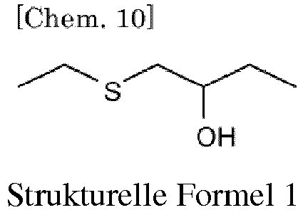
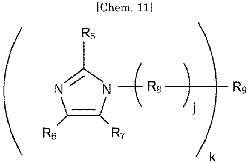

- Verfahren zum Herstellen eines Flüssigkeitsstrahlkopfes (100) nach Anspruch 1, Folgendes beinhaltend:Vermitteln eines gehärteten Produkts einer Harzzusammensetzung an das erste Glied,Verbinden des ersten Gliedes und des zweiten Gliedes miteinander über die Harzzusammensetzung; undAufbringen von Energie auf die Harzzusammensetzung, um die Harzzusammensetzung zu härten und die Harzschicht (113) zu bilden.
- Flüssigkeitsstrahlgerät, Folgendes beinhaltend:
den Flüssigkeitsstrahlkopf (100) nach einem der Ansprüche 1 bis 12. - Bilderzeugungsgerät, Folgendes beinhaltend:eine Gehäuseeinheit, konfiguriert zum Aufnehmen einer Tintenstrahltinte, undeinen Flüssigkeitsstrahlkopf (100), konfiguriert zum Aufbringen eines Stoßes auf die Tintenstrahltinte, um die Tinte auszuschleudern und ein Bild über einem Aufzeichnungsmedium aufzuzeichnen,wobei der Flüssigkeitsstrahlkopf der Flüssigkeitsstrahlkopf nach einem der Ansprüche 1 bis 12 ist.
Applications Claiming Priority (2)
| Application Number | Priority Date | Filing Date | Title |
|---|---|---|---|
| JP2014107209A JP6331688B2 (ja) | 2014-05-23 | 2014-05-23 | 液体吐出ヘッド及びその製造方法、並びに液体吐出装置及び画像形成装置 |
| PCT/JP2015/002501 WO2015178010A1 (en) | 2014-05-23 | 2015-05-19 | Liquid jet head and method for producing same, and liquid jet apparatus and image forming apparatus |
Publications (3)
| Publication Number | Publication Date |
|---|---|
| EP3145723A1 EP3145723A1 (de) | 2017-03-29 |
| EP3145723A4 EP3145723A4 (de) | 2017-08-09 |
| EP3145723B1 true EP3145723B1 (de) | 2018-09-05 |
Family
ID=54553691
Family Applications (1)
| Application Number | Title | Priority Date | Filing Date |
|---|---|---|---|
| EP15796728.2A Active EP3145723B1 (de) | 2014-05-23 | 2015-05-19 | Flüssigkeitsstrahlkopf und verfahren zur herstellung davon sowie flüssigkeitsstrahlvorrichtung und bilderzeugungsvorrichtung |
Country Status (7)
| Country | Link |
|---|---|
| US (1) | US9757944B2 (de) |
| EP (1) | EP3145723B1 (de) |
| JP (1) | JP6331688B2 (de) |
| CN (1) | CN106660363B (de) |
| CA (1) | CA2945082C (de) |
| RU (1) | RU2664650C2 (de) |
| WO (1) | WO2015178010A1 (de) |
Families Citing this family (23)
| Publication number | Priority date | Publication date | Assignee | Title |
|---|---|---|---|---|
| TW201703208A (zh) | 2015-05-19 | 2017-01-16 | 塔克圖科技有限公司 | 用於電子產品的熱成型塑料罩和相關的製造方法 |
| JP6617776B2 (ja) * | 2016-01-19 | 2019-12-11 | 株式会社リコー | インクジェット記録装置、及びインクジェット記録方法 |
| CN109177492B (zh) * | 2016-02-02 | 2020-09-11 | 株式会社理光 | 油墨排出装置和油墨排出方法 |
| CN108928118B (zh) * | 2017-05-26 | 2020-01-14 | 精工爱普生株式会社 | 喷嘴板、液体喷射头、液体喷射装置以及喷嘴板的制造方法 |
| JP2020523450A (ja) * | 2017-06-12 | 2020-08-06 | スリーエム イノベイティブ プロパティズ カンパニー | エポキシ/チオール樹脂組成物、方法、及びテープ |
| JP7105048B2 (ja) * | 2017-09-29 | 2022-07-22 | 理想科学工業株式会社 | インクジェット印刷装置 |
| JP7081233B2 (ja) | 2018-03-15 | 2022-06-07 | 株式会社リコー | 液体吐出ヘッド及びその製造方法、液体吐出装置、及び画像形成装置 |
| CN108410394A (zh) * | 2018-04-02 | 2018-08-17 | 浙江凯达文具用品有限公司 | 一种水性多功能液体胶及其制备方法 |
| JP2020019204A (ja) | 2018-07-31 | 2020-02-06 | 株式会社リコー | 液体吐出ヘッド、液体吐出ユニット、液体を吐出する装置及び液体吐出ヘッドの製造方法 |
| EP3722841A1 (de) * | 2019-04-08 | 2020-10-14 | Canon Kabushiki Kaisha | Diffraktives optisches element, optische vorrichtung und bildgebungsvorrichtung |
| JP7596118B2 (ja) * | 2020-01-17 | 2024-12-09 | キヤノン株式会社 | エポキシ樹脂組成物の製造方法、そのエポキシ樹脂組成物を用いた液体吐出ヘッド、及びその液体吐出ヘッドの製造方法 |
| US12234331B2 (en) | 2020-01-17 | 2025-02-25 | Canon Kabushiki Kaisha | Method for producing epoxy resin composition |
| WO2022212557A1 (en) | 2021-03-31 | 2022-10-06 | Quadratic 3D, Inc. | Photohardenable compositions, methods, and a stabilizer |
| CN118103214A (zh) * | 2021-09-16 | 2024-05-28 | 柯尼卡美能达株式会社 | 喷墨装置 |
| CN114015335A (zh) * | 2021-11-09 | 2022-02-08 | 国庆荣 | 一种环境友好型防水涂料及其制备方法 |
| CN114799031B (zh) * | 2022-04-20 | 2023-05-26 | 无锡神意环件法兰有限公司 | 轮胎模具用锻件的生产工艺及其用途 |
| JP2024007905A (ja) * | 2022-07-06 | 2024-01-19 | 東京エレクトロン株式会社 | プラズマ処理装置及びプラズマ処理方法 |
| CN115521743B (zh) * | 2022-09-11 | 2023-07-25 | 广州天赐高新材料股份有限公司 | 半导体加工用粘合剂及提高半导体加工性能的方法 |
| JPWO2024075602A1 (de) * | 2022-10-07 | 2024-04-11 | ||
| JP2024171383A (ja) | 2023-05-30 | 2024-12-12 | 株式会社リコー | 液体吐出ヘッド及びその製造方法、液体吐出ユニット、並びに液体吐出装置 |
| WO2025169546A1 (ja) * | 2024-02-08 | 2025-08-14 | コニカミノルタ株式会社 | インクジェットヘッド、その製造方法および画像形成装置 |
| WO2025238926A1 (ja) * | 2024-05-13 | 2025-11-20 | コニカミノルタ株式会社 | 画像形成方法 |
| JP7700981B1 (ja) * | 2024-05-13 | 2025-07-01 | コニカミノルタ株式会社 | 画像形成方法 |
Family Cites Families (17)
| Publication number | Priority date | Publication date | Assignee | Title |
|---|---|---|---|---|
| JP3015905B2 (ja) | 1991-03-05 | 2000-03-06 | オムロン株式会社 | 自動販売機の防犯システム |
| JP4715010B2 (ja) * | 2001-03-27 | 2011-07-06 | 味の素株式会社 | 硬化性エポキシ樹脂組成物、接着剤、及びシール剤 |
| JP2003020339A (ja) | 2001-07-10 | 2003-01-24 | Nippon Kayaku Co Ltd | 光硬化型樹脂組成物並びにその硬化物 |
| JP4882201B2 (ja) | 2004-02-09 | 2012-02-22 | コニカミノルタホールディングス株式会社 | インクジェット記録方法 |
| JP4987286B2 (ja) * | 2005-03-18 | 2012-07-25 | コニカミノルタホールディングス株式会社 | インクジェットヘッド及びインクジェットヘッドの製造方法 |
| US20060207720A1 (en) * | 2005-03-18 | 2006-09-21 | Konica Minolta Holdings, Inc. | Manufacturing method of inkjet head, and adhesive agent composition |
| JP4277898B2 (ja) | 2006-12-25 | 2009-06-10 | セイコーエプソン株式会社 | インクジェット記録方法 |
| JP5279117B2 (ja) * | 2008-05-28 | 2013-09-04 | コニカミノルタ株式会社 | インクジェットヘッド |
| JP5700689B2 (ja) * | 2010-02-10 | 2015-04-15 | リンテック株式会社 | 硬化性組成物、硬化物および硬化性組成物の使用方法 |
| JP5707806B2 (ja) | 2010-09-16 | 2015-04-30 | 株式会社リコー | 液体吐出ヘッド及び画像形成装置 |
| JP2013059966A (ja) | 2011-09-15 | 2013-04-04 | Ricoh Co Ltd | 液体吐出ヘッド |
| JP5796502B2 (ja) * | 2012-01-31 | 2015-10-21 | 三菱化学株式会社 | エポキシ樹脂、エポキシ樹脂の製造方法及びエポキシ樹脂組成物 |
| US9150706B2 (en) * | 2012-03-22 | 2015-10-06 | Hitachi Chemical Company, Ltd. | Photo curable resin composition, imaging display device and production method thereof |
| JP5591361B2 (ja) * | 2012-04-18 | 2014-09-17 | キヤノン株式会社 | インクジェット記録ヘッド |
| JP6194767B2 (ja) | 2013-03-14 | 2017-09-13 | 株式会社リコー | 液体吐出ヘッド及び画像形成装置 |
| JP6071718B2 (ja) * | 2013-04-10 | 2017-02-01 | キヤノン株式会社 | 感光性ネガ型樹脂組成物 |
| JP6217170B2 (ja) | 2013-06-23 | 2017-10-25 | 株式会社リコー | 液体吐出ヘッド及び画像形成装置 |
-
2014
- 2014-05-23 JP JP2014107209A patent/JP6331688B2/ja active Active
-
2015
- 2015-05-19 WO PCT/JP2015/002501 patent/WO2015178010A1/en not_active Ceased
- 2015-05-19 RU RU2016150388A patent/RU2664650C2/ru active
- 2015-05-19 CA CA2945082A patent/CA2945082C/en active Active
- 2015-05-19 CN CN201580026761.7A patent/CN106660363B/zh active Active
- 2015-05-19 EP EP15796728.2A patent/EP3145723B1/de active Active
- 2015-05-19 US US15/305,723 patent/US9757944B2/en active Active
Non-Patent Citations (1)
| Title |
|---|
| None * |
Also Published As
| Publication number | Publication date |
|---|---|
| RU2016150388A3 (de) | 2018-06-26 |
| CA2945082A1 (en) | 2015-11-26 |
| WO2015178010A1 (en) | 2015-11-26 |
| CN106660363B (zh) | 2018-07-06 |
| CA2945082C (en) | 2019-05-14 |
| US9757944B2 (en) | 2017-09-12 |
| RU2016150388A (ru) | 2018-06-26 |
| EP3145723A4 (de) | 2017-08-09 |
| JP2015221541A (ja) | 2015-12-10 |
| RU2664650C2 (ru) | 2018-08-21 |
| JP6331688B2 (ja) | 2018-05-30 |
| CN106660363A (zh) | 2017-05-10 |
| US20170043580A1 (en) | 2017-02-16 |
| EP3145723A1 (de) | 2017-03-29 |
Similar Documents
| Publication | Publication Date | Title |
|---|---|---|
| EP3145723B1 (de) | Flüssigkeitsstrahlkopf und verfahren zur herstellung davon sowie flüssigkeitsstrahlvorrichtung und bilderzeugungsvorrichtung | |
| US9463623B2 (en) | Liquid ejection head and image forming apparatus incorporating same | |
| US10717297B2 (en) | Inkjet recording method and inkjet recording apparatus | |
| US8752948B2 (en) | Inkjet recording ink containing fluorine based surfactant, inkjet recording ink set, and inkjet recording apparatus containing the inkjet recording ink | |
| EP2970703B1 (de) | Tintenstrahlaufzeichnungstinte, tintenpatrone, tintenstrahlaufzeichnungsverfahren, tintenstrahlaufzeichnungsvorrichtung und mit tinte aufgezeichnetes material | |
| US8857962B2 (en) | Image forming method and image formed record | |
| US9205652B2 (en) | Liquid ejection head, and image forming apparatus using the liquid ejection head | |
| EP3184307B1 (de) | Druckvorrichtung und druckverfahren | |
| US9045659B2 (en) | Inkjet recording ink and inkjet recording device using the same | |
| US8979989B2 (en) | Ink for inkjet recording, ink cartridge and inkjet recording apparatus | |
| EP4470780B1 (de) | Flüssigkeitsausstosskopf, verfahren zur herstellung eines flüssigkeitsausstosskopfes, flüssigkeitsausstossanordnung und flüssigkeitsausstossvorrichtung | |
| EP3686254B1 (de) | Tinte, verfahren zur herstellung von tinte, druckverfahren und druckvorrichtung | |
| JP2013059966A (ja) | 液体吐出ヘッド | |
| US10589528B2 (en) | Liquid discharge head, method for producing the same, liquid discharge apparatus, and image forming apparatus | |
| JP5810673B2 (ja) | 液体吐出ヘッド及び画像形成装置 | |
| EP1607455B1 (de) | Tinte für das Tintenstrahldruckverfahren auf Wasserbasis | |
| JP2018154668A (ja) | 硬化性組成物、及び液体吐出ヘッド |
Legal Events
| Date | Code | Title | Description |
|---|---|---|---|
| STAA | Information on the status of an ep patent application or granted ep patent |
Free format text: STATUS: THE INTERNATIONAL PUBLICATION HAS BEEN MADE |
|
| PUAI | Public reference made under article 153(3) epc to a published international application that has entered the european phase |
Free format text: ORIGINAL CODE: 0009012 |
|
| STAA | Information on the status of an ep patent application or granted ep patent |
Free format text: STATUS: REQUEST FOR EXAMINATION WAS MADE |
|
| 17P | Request for examination filed |
Effective date: 20161102 |
|
| AK | Designated contracting states |
Kind code of ref document: A1 Designated state(s): AL AT BE BG CH CY CZ DE DK EE ES FI FR GB GR HR HU IE IS IT LI LT LU LV MC MK MT NL NO PL PT RO RS SE SI SK SM TR |
|
| AX | Request for extension of the european patent |
Extension state: BA ME |
|
| A4 | Supplementary search report drawn up and despatched |
Effective date: 20170706 |
|
| RIC1 | Information provided on ipc code assigned before grant |
Ipc: B41J 2/16 20060101ALI20170630BHEP Ipc: C08G 59/24 20060101ALI20170630BHEP Ipc: B41J 2/14 20060101AFI20170630BHEP Ipc: C08G 59/50 20060101ALI20170630BHEP Ipc: C08G 59/66 20060101ALI20170630BHEP |
|
| DAV | Request for validation of the european patent (deleted) | ||
| DAX | Request for extension of the european patent (deleted) | ||
| GRAP | Despatch of communication of intention to grant a patent |
Free format text: ORIGINAL CODE: EPIDOSNIGR1 |
|
| STAA | Information on the status of an ep patent application or granted ep patent |
Free format text: STATUS: GRANT OF PATENT IS INTENDED |
|
| INTG | Intention to grant announced |
Effective date: 20180322 |
|
| GRAS | Grant fee paid |
Free format text: ORIGINAL CODE: EPIDOSNIGR3 |
|
| GRAA | (expected) grant |
Free format text: ORIGINAL CODE: 0009210 |
|
| STAA | Information on the status of an ep patent application or granted ep patent |
Free format text: STATUS: THE PATENT HAS BEEN GRANTED |
|
| AK | Designated contracting states |
Kind code of ref document: B1 Designated state(s): AL AT BE BG CH CY CZ DE DK EE ES FI FR GB GR HR HU IE IS IT LI LT LU LV MC MK MT NL NO PL PT RO RS SE SI SK SM TR |
|
| REG | Reference to a national code |
Ref country code: GB Ref legal event code: FG4D |
|
| REG | Reference to a national code |
Ref country code: CH Ref legal event code: EP |
|
| REG | Reference to a national code |
Ref country code: AT Ref legal event code: REF Ref document number: 1037335 Country of ref document: AT Kind code of ref document: T Effective date: 20180915 |
|
| REG | Reference to a national code |
Ref country code: DE Ref legal event code: R096 Ref document number: 602015015855 Country of ref document: DE |
|
| REG | Reference to a national code |
Ref country code: IE Ref legal event code: FG4D |
|
| REG | Reference to a national code |
Ref country code: NL Ref legal event code: MP Effective date: 20180905 |
|
| REG | Reference to a national code |
Ref country code: LT Ref legal event code: MG4D |
|
| PG25 | Lapsed in a contracting state [announced via postgrant information from national office to epo] |
Ref country code: RS Free format text: LAPSE BECAUSE OF FAILURE TO SUBMIT A TRANSLATION OF THE DESCRIPTION OR TO PAY THE FEE WITHIN THE PRESCRIBED TIME-LIMIT Effective date: 20180905 Ref country code: LT Free format text: LAPSE BECAUSE OF FAILURE TO SUBMIT A TRANSLATION OF THE DESCRIPTION OR TO PAY THE FEE WITHIN THE PRESCRIBED TIME-LIMIT Effective date: 20180905 Ref country code: BG Free format text: LAPSE BECAUSE OF FAILURE TO SUBMIT A TRANSLATION OF THE DESCRIPTION OR TO PAY THE FEE WITHIN THE PRESCRIBED TIME-LIMIT Effective date: 20181205 Ref country code: SE Free format text: LAPSE BECAUSE OF FAILURE TO SUBMIT A TRANSLATION OF THE DESCRIPTION OR TO PAY THE FEE WITHIN THE PRESCRIBED TIME-LIMIT Effective date: 20180905 Ref country code: FI Free format text: LAPSE BECAUSE OF FAILURE TO SUBMIT A TRANSLATION OF THE DESCRIPTION OR TO PAY THE FEE WITHIN THE PRESCRIBED TIME-LIMIT Effective date: 20180905 Ref country code: NO Free format text: LAPSE BECAUSE OF FAILURE TO SUBMIT A TRANSLATION OF THE DESCRIPTION OR TO PAY THE FEE WITHIN THE PRESCRIBED TIME-LIMIT Effective date: 20181205 Ref country code: GR Free format text: LAPSE BECAUSE OF FAILURE TO SUBMIT A TRANSLATION OF THE DESCRIPTION OR TO PAY THE FEE WITHIN THE PRESCRIBED TIME-LIMIT Effective date: 20181206 |
|
| REG | Reference to a national code |
Ref country code: AT Ref legal event code: MK05 Ref document number: 1037335 Country of ref document: AT Kind code of ref document: T Effective date: 20180905 |
|
| PG25 | Lapsed in a contracting state [announced via postgrant information from national office to epo] |
Ref country code: LV Free format text: LAPSE BECAUSE OF FAILURE TO SUBMIT A TRANSLATION OF THE DESCRIPTION OR TO PAY THE FEE WITHIN THE PRESCRIBED TIME-LIMIT Effective date: 20180905 Ref country code: HR Free format text: LAPSE BECAUSE OF FAILURE TO SUBMIT A TRANSLATION OF THE DESCRIPTION OR TO PAY THE FEE WITHIN THE PRESCRIBED TIME-LIMIT Effective date: 20180905 Ref country code: AL Free format text: LAPSE BECAUSE OF FAILURE TO SUBMIT A TRANSLATION OF THE DESCRIPTION OR TO PAY THE FEE WITHIN THE PRESCRIBED TIME-LIMIT Effective date: 20180905 |
|
| PG25 | Lapsed in a contracting state [announced via postgrant information from national office to epo] |
Ref country code: NL Free format text: LAPSE BECAUSE OF FAILURE TO SUBMIT A TRANSLATION OF THE DESCRIPTION OR TO PAY THE FEE WITHIN THE PRESCRIBED TIME-LIMIT Effective date: 20180905 Ref country code: ES Free format text: LAPSE BECAUSE OF FAILURE TO SUBMIT A TRANSLATION OF THE DESCRIPTION OR TO PAY THE FEE WITHIN THE PRESCRIBED TIME-LIMIT Effective date: 20180905 Ref country code: EE Free format text: LAPSE BECAUSE OF FAILURE TO SUBMIT A TRANSLATION OF THE DESCRIPTION OR TO PAY THE FEE WITHIN THE PRESCRIBED TIME-LIMIT Effective date: 20180905 Ref country code: IT Free format text: LAPSE BECAUSE OF FAILURE TO SUBMIT A TRANSLATION OF THE DESCRIPTION OR TO PAY THE FEE WITHIN THE PRESCRIBED TIME-LIMIT Effective date: 20180905 Ref country code: AT Free format text: LAPSE BECAUSE OF FAILURE TO SUBMIT A TRANSLATION OF THE DESCRIPTION OR TO PAY THE FEE WITHIN THE PRESCRIBED TIME-LIMIT Effective date: 20180905 Ref country code: RO Free format text: LAPSE BECAUSE OF FAILURE TO SUBMIT A TRANSLATION OF THE DESCRIPTION OR TO PAY THE FEE WITHIN THE PRESCRIBED TIME-LIMIT Effective date: 20180905 Ref country code: CZ Free format text: LAPSE BECAUSE OF FAILURE TO SUBMIT A TRANSLATION OF THE DESCRIPTION OR TO PAY THE FEE WITHIN THE PRESCRIBED TIME-LIMIT Effective date: 20180905 Ref country code: PL Free format text: LAPSE BECAUSE OF FAILURE TO SUBMIT A TRANSLATION OF THE DESCRIPTION OR TO PAY THE FEE WITHIN THE PRESCRIBED TIME-LIMIT Effective date: 20180905 Ref country code: IS Free format text: LAPSE BECAUSE OF FAILURE TO SUBMIT A TRANSLATION OF THE DESCRIPTION OR TO PAY THE FEE WITHIN THE PRESCRIBED TIME-LIMIT Effective date: 20190105 |
|
| PG25 | Lapsed in a contracting state [announced via postgrant information from national office to epo] |
Ref country code: SK Free format text: LAPSE BECAUSE OF FAILURE TO SUBMIT A TRANSLATION OF THE DESCRIPTION OR TO PAY THE FEE WITHIN THE PRESCRIBED TIME-LIMIT Effective date: 20180905 Ref country code: PT Free format text: LAPSE BECAUSE OF FAILURE TO SUBMIT A TRANSLATION OF THE DESCRIPTION OR TO PAY THE FEE WITHIN THE PRESCRIBED TIME-LIMIT Effective date: 20190105 Ref country code: SM Free format text: LAPSE BECAUSE OF FAILURE TO SUBMIT A TRANSLATION OF THE DESCRIPTION OR TO PAY THE FEE WITHIN THE PRESCRIBED TIME-LIMIT Effective date: 20180905 |
|
| REG | Reference to a national code |
Ref country code: DE Ref legal event code: R097 Ref document number: 602015015855 Country of ref document: DE |
|
| PLBE | No opposition filed within time limit |
Free format text: ORIGINAL CODE: 0009261 |
|
| STAA | Information on the status of an ep patent application or granted ep patent |
Free format text: STATUS: NO OPPOSITION FILED WITHIN TIME LIMIT |
|
| PG25 | Lapsed in a contracting state [announced via postgrant information from national office to epo] |
Ref country code: DK Free format text: LAPSE BECAUSE OF FAILURE TO SUBMIT A TRANSLATION OF THE DESCRIPTION OR TO PAY THE FEE WITHIN THE PRESCRIBED TIME-LIMIT Effective date: 20180905 |
|
| 26N | No opposition filed |
Effective date: 20190606 |
|
| PG25 | Lapsed in a contracting state [announced via postgrant information from national office to epo] |
Ref country code: SI Free format text: LAPSE BECAUSE OF FAILURE TO SUBMIT A TRANSLATION OF THE DESCRIPTION OR TO PAY THE FEE WITHIN THE PRESCRIBED TIME-LIMIT Effective date: 20180905 |
|
| REG | Reference to a national code |
Ref country code: CH Ref legal event code: PL |
|
| PG25 | Lapsed in a contracting state [announced via postgrant information from national office to epo] |
Ref country code: MC Free format text: LAPSE BECAUSE OF FAILURE TO SUBMIT A TRANSLATION OF THE DESCRIPTION OR TO PAY THE FEE WITHIN THE PRESCRIBED TIME-LIMIT Effective date: 20180905 Ref country code: LI Free format text: LAPSE BECAUSE OF NON-PAYMENT OF DUE FEES Effective date: 20190531 Ref country code: CH Free format text: LAPSE BECAUSE OF NON-PAYMENT OF DUE FEES Effective date: 20190531 |
|
| REG | Reference to a national code |
Ref country code: BE Ref legal event code: MM Effective date: 20190531 |
|
| PG25 | Lapsed in a contracting state [announced via postgrant information from national office to epo] |
Ref country code: LU Free format text: LAPSE BECAUSE OF NON-PAYMENT OF DUE FEES Effective date: 20190519 |
|
| PG25 | Lapsed in a contracting state [announced via postgrant information from national office to epo] |
Ref country code: TR Free format text: LAPSE BECAUSE OF FAILURE TO SUBMIT A TRANSLATION OF THE DESCRIPTION OR TO PAY THE FEE WITHIN THE PRESCRIBED TIME-LIMIT Effective date: 20180905 |
|
| PG25 | Lapsed in a contracting state [announced via postgrant information from national office to epo] |
Ref country code: IE Free format text: LAPSE BECAUSE OF NON-PAYMENT OF DUE FEES Effective date: 20190519 |
|
| PG25 | Lapsed in a contracting state [announced via postgrant information from national office to epo] |
Ref country code: BE Free format text: LAPSE BECAUSE OF NON-PAYMENT OF DUE FEES Effective date: 20190531 |
|
| PG25 | Lapsed in a contracting state [announced via postgrant information from national office to epo] |
Ref country code: CY Free format text: LAPSE BECAUSE OF FAILURE TO SUBMIT A TRANSLATION OF THE DESCRIPTION OR TO PAY THE FEE WITHIN THE PRESCRIBED TIME-LIMIT Effective date: 20180905 |
|
| PG25 | Lapsed in a contracting state [announced via postgrant information from national office to epo] |
Ref country code: MT Free format text: LAPSE BECAUSE OF FAILURE TO SUBMIT A TRANSLATION OF THE DESCRIPTION OR TO PAY THE FEE WITHIN THE PRESCRIBED TIME-LIMIT Effective date: 20180905 Ref country code: HU Free format text: LAPSE BECAUSE OF FAILURE TO SUBMIT A TRANSLATION OF THE DESCRIPTION OR TO PAY THE FEE WITHIN THE PRESCRIBED TIME-LIMIT; INVALID AB INITIO Effective date: 20150519 |
|
| PG25 | Lapsed in a contracting state [announced via postgrant information from national office to epo] |
Ref country code: MK Free format text: LAPSE BECAUSE OF FAILURE TO SUBMIT A TRANSLATION OF THE DESCRIPTION OR TO PAY THE FEE WITHIN THE PRESCRIBED TIME-LIMIT Effective date: 20180905 |
|
| P01 | Opt-out of the competence of the unified patent court (upc) registered |
Effective date: 20230522 |
|
| PGFP | Annual fee paid to national office [announced via postgrant information from national office to epo] |
Ref country code: DE Payment date: 20250521 Year of fee payment: 11 |
|
| PGFP | Annual fee paid to national office [announced via postgrant information from national office to epo] |
Ref country code: GB Payment date: 20250521 Year of fee payment: 11 |
|
| PGFP | Annual fee paid to national office [announced via postgrant information from national office to epo] |
Ref country code: FR Payment date: 20250528 Year of fee payment: 11 |