EP3145730B1 - Profil de pneu et forme de moulage - Google Patents
Profil de pneu et forme de moulage Download PDFInfo
- Publication number
- EP3145730B1 EP3145730B1 EP15720095.7A EP15720095A EP3145730B1 EP 3145730 B1 EP3145730 B1 EP 3145730B1 EP 15720095 A EP15720095 A EP 15720095A EP 3145730 B1 EP3145730 B1 EP 3145730B1
- Authority
- EP
- European Patent Office
- Prior art keywords
- width direction
- angle
- tire
- sipe
- radial direction
- Prior art date
- Legal status (The legal status is an assumption and is not a legal conclusion. Google has not performed a legal analysis and makes no representation as to the accuracy of the status listed.)
- Active
Links
Images




Classifications
-
- B—PERFORMING OPERATIONS; TRANSPORTING
- B60—VEHICLES IN GENERAL
- B60C—VEHICLE TYRES; TYRE INFLATION; TYRE CHANGING; CONNECTING VALVES TO INFLATABLE ELASTIC BODIES IN GENERAL; DEVICES OR ARRANGEMENTS RELATED TO TYRES
- B60C11/00—Tyre tread bands; Tread patterns; Anti-skid inserts
- B60C11/03—Tread patterns
- B60C11/12—Tread patterns characterised by the use of narrow slits or incisions, e.g. sipes
- B60C11/1204—Tread patterns characterised by the use of narrow slits or incisions, e.g. sipes with special shape of the sipe
- B60C11/1218—Three-dimensional shape with regard to depth and extending direction
-
- B—PERFORMING OPERATIONS; TRANSPORTING
- B60—VEHICLES IN GENERAL
- B60C—VEHICLE TYRES; TYRE INFLATION; TYRE CHANGING; CONNECTING VALVES TO INFLATABLE ELASTIC BODIES IN GENERAL; DEVICES OR ARRANGEMENTS RELATED TO TYRES
- B60C11/00—Tyre tread bands; Tread patterns; Anti-skid inserts
- B60C11/03—Tread patterns
- B60C11/12—Tread patterns characterised by the use of narrow slits or incisions, e.g. sipes
- B60C11/1236—Tread patterns characterised by the use of narrow slits or incisions, e.g. sipes with special arrangements in the tread pattern
- B60C11/124—Tread patterns characterised by the use of narrow slits or incisions, e.g. sipes with special arrangements in the tread pattern inclined with regard to a plane normal to the tread surface
-
- B—PERFORMING OPERATIONS; TRANSPORTING
- B60—VEHICLES IN GENERAL
- B60C—VEHICLE TYRES; TYRE INFLATION; TYRE CHANGING; CONNECTING VALVES TO INFLATABLE ELASTIC BODIES IN GENERAL; DEVICES OR ARRANGEMENTS RELATED TO TYRES
- B60C11/00—Tyre tread bands; Tread patterns; Anti-skid inserts
- B60C11/03—Tread patterns
- B60C11/12—Tread patterns characterised by the use of narrow slits or incisions, e.g. sipes
- B60C11/1204—Tread patterns characterised by the use of narrow slits or incisions, e.g. sipes with special shape of the sipe
- B60C2011/1213—Tread patterns characterised by the use of narrow slits or incisions, e.g. sipes with special shape of the sipe sinusoidal or zigzag at the tread surface
-
- B—PERFORMING OPERATIONS; TRANSPORTING
- B60—VEHICLES IN GENERAL
- B60C—VEHICLE TYRES; TYRE INFLATION; TYRE CHANGING; CONNECTING VALVES TO INFLATABLE ELASTIC BODIES IN GENERAL; DEVICES OR ARRANGEMENTS RELATED TO TYRES
- B60C11/00—Tyre tread bands; Tread patterns; Anti-skid inserts
- B60C11/03—Tread patterns
- B60C11/12—Tread patterns characterised by the use of narrow slits or incisions, e.g. sipes
- B60C11/1204—Tread patterns characterised by the use of narrow slits or incisions, e.g. sipes with special shape of the sipe
- B60C2011/1227—Tread patterns characterised by the use of narrow slits or incisions, e.g. sipes with special shape of the sipe having different shape within the pattern
Definitions
- the invention relates to a tire profile and a molding form for a pneumatic tire of an automobile, by means of which the automobile can be driven along an underground.
- a pneumatic tire comprising a plurality of sipes in a tread portion of a tire profile for providing a better grip of the tire on the underground at winter conditions.
- the sipes comprise a zig-zag extension in a width direction mainly parallel to a turning axis of the tire.
- the sipes further comprises a zig-zag extension in radial direction.
- Each sipe comprises in radial direction a first portion connected to a second portion by a smaller first angle and third portion connected to the second portion via a broader second angle, wherein the first angle and the second angle are constant along the zig-zag extension in width direction for each separate sipe.
- WO 2012/001488 A1 describes a tread of a tire comprising sipes with a laterally protruding dove tail like ridge.
- the ridge comprises two inclined portions connected via an angle which changes along width direction.
- EP 1 55 142 A2 describes a tire with sipes comprising straight parts arranged in a zig-zag manner in width direction and straight portions arranged in a zig-zag manner in radial direction.
- EP 2 821 158 A1 describes a tire with sinusoidal sipes comprising a continuous transition between different inclined portions in radial direction.
- a tire profile of a pneumatic tire of an automobile comprising a tread portion comprising at least one sipe, the sipe comprising an extension in a width direction and a depth in a radial direction, wherein the sipe comprises a first portion, a second portion arranged radially inward of the first portion and at least one further portion, wherein the further portion is connected to a portion arranged above the further portion in the radial direction by at their connecting line, wherein the sipe comprises a first part, a second part arranged directly besides the first part in the width direction and at least one third part directly besides, i. e.
- the first part is inclined to the width direction by an acute angle ⁇ 1
- the second part is inclined to the width direction by an acute angle ⁇ 2 different to ⁇ 1
- the third part is inclined to the width direction by an acute angle ⁇ 3 different to ⁇ 1 and different to ⁇ 2
- the mathematical values of ⁇ 1 and ⁇ 2 are both positive or negative along at leat a part of the radial direction and/or the mathematical values of ⁇ 2 and ⁇ 3 are both positive or negative along at least a part of the radial direction
- the first part and the second part are inclined to each other along their connecting line by an angle ⁇ 1
- the second part and the third part are inclined to each other along their connecting line by an angle ⁇ 2
- the angle ⁇ 1 and/or the angle ⁇ 2 changes along the width direction continuously in a range of 90° ⁇ ⁇ 1 ⁇ 300° and/or in a range of 90° ⁇ ⁇ 2 ⁇ 300°.
- the first portion is inclined to the radial direction by an acute angle ⁇ 1
- the second portion is inclined to the radial direction by an acute angle ⁇ 2 different to ⁇ 1
- the further portion is inclined to the radial direction by an acute angle ⁇ x different to ⁇ 1 and different to ⁇ 2
- the mathematical values of ⁇ 1 and ⁇ 2 are both positive or negative at least partially along the width direction and/or the mathematical values of ⁇ 2 and ⁇ x are both positive or negative at least partially along the width direction.
- ⁇ 2 is not positive and negative at the same time.
- ⁇ 2 is not positive and negative at the same time.
- an irregular formed slit inside the tire profile may be provided so that the edges of rubber blocks between two subsequent sipes may dig into a snowy or icy surface and/or through a fluid film on a road at bad weather conditions. This leads to a good grip of a tire with such kind of a tire profile even on low friction surfaces. At the same time a high stiffness of the tire profile and a good dry road performance is provided. Due to the same mathematical value of subsequent portions or parts of the sipe in radial direction and/or width direction the inclination changes at its respective connection line but not the orientation with respect the radial direction or width direction.
- the sipe is not straight and may comprise a non-zig-zag extension in radial direction and/or in width direction.
- the form of the sipe may differ both from a straight as well as from a pure zig-zag course in radial direction and/or in width direction, wherein the sipe may comprise a zig-zag course in one direction and/or only partially in radial direction and/or in width direction.
- a protrusion and a corresponding depression is formed in adjacent blocks of the tire profile spaced by the sipe, wherein one bigger and one smaller protrusion/depression can be formed one after the other in radial direction and/or in width direction.
- the bigger protrusion Due to the change of the inclination of the bigger protrusion/depression the bigger protrusion can be blocked at the tip of the protrusion inside the bigger depression leading to an increased stiffness under a lower load and may be further blocked at the side faces at a higher load, wherein the smaller protrusion/depression may block at a further different load. Due to the design of the smaller and bigger protrusion/depression of the blocks defined by the form of the sipes the stiffness of tire may be different in dependence of the applied load. This enables a tire which comprises a low stiffness at low load, like normal straight forward drive of the automobile, leading to a low wear.
- the tire may comprise a high stiffness at high load, like during a braking situation or cornering, leading to a good grip to the underground.
- Particularly bigger and smaller protrusion/depression are arranged alternatively in radial direction and in width direction so that the bigger protrusion/depression may block with each other in a direction inclined to the radial direction as well as to the width direction leading a high stiffness at high load. Due to the same mathematical value of subsequent portions or parts of the sipe in radial direction and/or width direction bigger and smaller protrusion/depression of adjacent blocks spaced to each other by the sipe are provided leading to a high stiffness, particularly at high load, and a low wear.
- the sipes extends usually only along a part of the width of a tire. If so, the width direction of the sipe may be inclined with respect to an axial direction of a tire comprising the tire profile. Particularly the inclination of the width direction to the axial direction is less than 45°, particularly less than 30°, preferably less than 15° and particularly preferred less than 5°. Further it is possible that the width direction is mainly parallel to the axial direction of the tire and/or the turning axis of the tire. When the sipe is straight in width direction the sipe extends along the width direction. When the sipe is not straight but curved, zig-zag-formed or else formed the width direction is the best fit straight line to the form of the sipe in top view or parallel to this best fit straight line.
- the angle between the second portion and the radial direction portion would be ⁇ 2 , wherein, if so, the angle between the third portion and the radial direction would be ⁇ 3 and so on.
- the angle ⁇ x is the angle between the x portion and the radial direction, wherein x is a natural positive number.
- a feature regarding the relative arrangement of the first portion and the radial direction may also apply for the relative arrangement of other portions to the radial direction, wherein different portions may have the same or a different relative arrangement to the radial direction as explained elsewhere, when a specific design of a sipe is regarded. Different discussed features of the relative arrangement of portions to the radial direction may be combined in one sipe at different portions, even when only explained with respect to the first portion exemplary.
- one portion of the pure zig-zag course may be constituted by two portions connected to each other via a connecting line by an angle ⁇ x , wherein these two portions are oriented in the same general orientation with a part in the forward running direction of the tire or against the forward running direction of the tire but with a different inclination to the radial direction by means of the different angles ⁇ .
- the angle between the second part and the width direction would be ⁇ 2 , wherein, if so, the angle between the third part and the width direction would be ⁇ 3 and so on.
- the angle ⁇ x is the angle between the x part and the width direction, wherein x is a natural positive number.
- a feature regarding the relative arrangement of the first part and the width direction may also apply for the relative arrangement of other parts to the width direction, wherein different parts may have the same or a different relative arrangement to the width direction as explained elsewhere, when a specific design of a sipe is regarded. Different discussed features of the relative arrangement of parts to the width direction may be combined in one sipe at different parts, even when only explained with respect to the first parts exemplary.
- one part of the pure zig-zag course may be constituted by two parts connected to each other via a connecting line by an angle ⁇ x , wherein these two parts are oriented in the same general orientation with a part in the same axial direction of the tire or against this axial direction of the tire but with a different inclination to the width direction by means of the different angles ⁇ .
- the first portion and the second portion are inclined to each other along their connecting line by an angle ⁇ 1 and the further portion is inclined to the portion arranged above, i. e. adjacent to, the further portion by an angle ⁇ x , wherein the angle ⁇ 1 and/or the angle ⁇ x changes along width direction continuously.
- the sipe comprises at least one further portion, wherein the further portion is connected to a portion arranged above the further portion in radial direction by a further connecting line and inclined to this portion by an angle ⁇ x , wherein the angle ⁇ x changes along width direction continuously.
- the angle between the second portion and the subsequent third portion would be ⁇ 2 , wherein, if so, the angle between the third portion and the subsequent forth portion would be ⁇ 3 and so on.
- the angle ⁇ x is the angle between the x portion and the x+1 portion, wherein x is a natural positive number.
- a feature regarding the relative arrangement of the first portion and the second portion may also apply for the relative arrangement of other portions, wherein different portions may have the same or a different relative arrangement as explained elsewhere, when a specific design of a sipe is regarded. Different discussed features of the relative arrangement of portions may be combined in one sipe at different pairs of portions, even when only explained with respect to the first portion and the second portion exemplary.
- the faces of the rubber blocks pointing to each other and defined by the form of the sipe become more irregular. Due to the irregular and more uneven faces of the adjacent blocks the blocks may easily engage each others so that the blocks may be interlocked increasing the stiffness of the tire profile.
- the angle ⁇ 1 between the first portion and the second portion of the sipe in radial direction is not constant or changes stepwise but changes continuously adjacent blocks spaced by the sipe may easily engage each other so that the blocks may be interlocked increasing the stiffness of the tire profile. This in turn increases the performance of the tire particularly regarding traction and/or in a breaking situation on a dry high friction surface. Further the wear resistance is increased due to a diminished slipping of the blocks. Due to the continuous change of the angle ⁇ 1 between the first portion and the second portion a good grip and a high efficiency at low as well as at high friction surfaces can be provided so that a tire with a good grip to an underground is possible.
- the angle ⁇ 1 is measured on the left side of the sipe, wherein the running surface of the tire profile points upwards at the regarded sipe.
- the sipe may comprises particularly partially a zig-zag course in radial direction this means that in radial direction an angle ⁇ between adjacent portions of the sipes in radial directions may comprise an angle ⁇ of less than 180° and more than 180° particularly in an alternating manner.
- the angle ⁇ 1 between the first portion and the second portion may start with an value of less than 180° or more than 180°.
- the continuous change of the angle ⁇ 1 may lead to an increasing or decreasing angle ⁇ 1 , wherein in a part in width direction the angle ⁇ 1 may increase and in another part in width direction the angle ⁇ 1 may decrease.
- an amount of the change of ⁇ 1 and at least one ⁇ x in width direction and/or the sign of the change of ⁇ 1 and at least one ⁇ x along width direction is different.
- the amount of the change ⁇ ' of the respective angle ⁇ is 0°/mm ⁇ ⁇ ' ⁇ 105°/mm, particularly 5°/mm ⁇ ⁇ ' ⁇ 70°/mm, preferably 10°/mm ⁇ ⁇ ' ⁇ 60°/mm and particularly preferred 20°/mm ⁇ ⁇ ' ⁇ 40°/mm.
- the derivation of the angle ⁇ to the path of the respective portion may be constant or may differ along the width direction. Due to this change of an angle ⁇ sufficiently irregular surfaces of the opposing blocks may be provided for facilitating an engagement of the blocks with each others.
- the stiffness of the tire profile may be increased without affecting a good grip to an underground significantly.
- At least one angle ⁇ changes at least along a part of the extension of the sipe in the width direction in a range of 40° ⁇ ⁇ ⁇ 300°, particularly 90° ⁇ ⁇ ⁇ 270°, preferably 135° ⁇ ⁇ ⁇ 225° and/or in a range of 40° ⁇ ⁇ ⁇ 180°, particularly 90° ⁇ ⁇ ⁇ 180°, preferably 135° ⁇ ⁇ ⁇ 180°.
- a portion may be inclined to the radial direction by an acute angle ⁇ with a positive mathematical value, wherein the angle ⁇ may decrease to zero and increases again with a positive mathematical value to its maximum absolute value or decreases further with a negative mathematical value to its maximum absolute value.
- a portion may be inclined to the radial direction by an acute angle ⁇ with a negative mathematical value, wherein the angle ⁇ may increase to zero and decreases again with a negative mathematical value to its maximum absolute value or increases further with a positive mathematical value to its maximum absolute value.
- the general orientation of a portion with an amount in forward running direction of the tire or against the forward running direction of the tire may stay or may change along the width direction. Due to this range for ⁇ sufficient irregular surfaces of the blocks may be provided for facilitating an engagement of the blocks with each others.
- the stiffness of the tire profile may be increased without affecting a good grip to an underground significantly.
- an acute angle at the connecting line between the first portion and the second portion and an acute angle at the connecting line between the second portion and the further portion is different at a discrete position in the width direction.
- an interlocking of adjacent blocks may occur at the value of ⁇ 1 but not at the value of ⁇ x or the respective acute angle, wherein at a different situation with different forces applied to the tire profile an interlocking of adjacent blocks may occur at the value of ⁇ x but not at the value of ⁇ 1 .
- a sufficient stiffness can be provided at a plurality of different situations.
- a plurality of portions arranged one after another in the radial direction wherein one end of each portion is arranged on a basic line in the radial direction and the other end of each portion is arranged spaced to the basic line by an amplitude, wherein the amplitude is constant for each portion at at least one discrete position in the width direction and/or the amplitude is different for different portions at least partially in the width direction.
- a part with a low amplitude between parts with a high amplitude may form a kind of a pocket in one block into which a corresponding protrusion of the opposite block may protrude, wherein the ground of the pocket may be not even but irregular, particularly saw-toothed. This provides differently formed parts where an interlocking of the blocks spaced by the sipe may occur.
- the stiffness of the tire profile may be increased without affecting a good grip to an underground significantly.
- the sipe comprises a first part and a second part arranged besides the first part in width direction, wherein the first part and the second part are inclined to each other along a connecting line by an angle ⁇ 1 particularly for forming a zig-zag-extension in width direction, wherein the angle ⁇ 1 changes along radial direction continuously. Since the angle ⁇ 1 between the first part and the second part of a particularly zig-zag course of the sipe in width direction is not constant or changes stepwise but changes continuously adjacent blocks spaced by the sipe may easily engage each other so that the blocks may be interlocked increasing the stiffness of the tire profile. This in turn increases the performance of the tire particularly regarding traction and/or in a breaking situation on a dry high friction surface.
- the wear resistance is increased due to a diminished slipping of the blocks. Due to the continuous change of the angle ⁇ 1 between the first part and the second part a good grip and a high efficiency at low as well as at high friction surfaces can be provided so that a tire with a good grip to an underground is possible.
- the angle between the second part and the subsequent third part would be ⁇ 2 , wherein, if so, the angle between the third part and the subsequent forth part would be ⁇ 3 and so on.
- the angle ⁇ x is the angle between the x part and the x+1 part, wherein x is a natural positive number.
- the angle ⁇ 1 is measured on the left side of the sipe.
- the sipe comprises a zig-zag course in width direction this means that in width direction an angle ⁇ between adjacent parts of the sipes in width directions may comprise an angle ⁇ of less than 180° and more than 180° particularly in an alternating manner.
- the angle ⁇ 1 between the first part and the second part may start with an value of less than 180° or more than 180°.
- the continuous change of the angle ⁇ 1 may lead to an increasing or decreasing angle ⁇ 1 , wherein in a part in radial direction the angle ⁇ 1 may increase and in another part in radial direction the angle ⁇ 1 may decrease.
- the first part is inclined to the width direction by an acute angle ⁇ 1 and the second part is inclined to the width direction by an acute angle ⁇ 2 .
- the further part may be inclined to the width direction by an acute angle ⁇ x .
- the angle between the second part and the width direction would be ⁇ 2 , wherein, if so, the angle between the third part and the width direction would be ⁇ 3 and so on.
- the angle ⁇ x is the angle between the x part and the width direction, wherein x is a natural positive number.
- the sipe may be designed similarly in width direction as in radial direction.
- angle ⁇ may apply also to angle ⁇ , respectively.
- angle ⁇ may apply also to angle ⁇ , respectively.
- an amount of the change of the angle ⁇ 1 and at least one angle ⁇ x in the width direction and/or the sign of the change of the angle ⁇ 1 and at least one angle ⁇ x along the width direction is different.
- the amount of the change ⁇ ' of the respective angle ⁇ is 0°/mm ⁇ ⁇ ' ⁇ 105°/mm, particularly 5°/mm ⁇ ⁇ ' ⁇ 70°/mm, preferably 10°/mm ⁇ ⁇ ' ⁇ 60°/mm and particularly preferred 20°/mm ⁇ ⁇ ' ⁇ 40°/mm.
- the derivation of the angle ⁇ to the path of the respective portion may be constant or may differ along the width direction.
- At least one angle ⁇ changes at least along a part of the extension of the sipe in width direction in a range of 40° ⁇ ⁇ ⁇ 300°, particularly 90° ⁇ ⁇ ⁇ 270°, preferably 135° ⁇ ⁇ ⁇ 225° and/or in a range of 40° ⁇ ⁇ ⁇ 180°, particularly 90° ⁇ ⁇ ⁇ 180°, preferably 135° ⁇ ⁇ ⁇ 180°.
- an acute angle at the connecting line between the first part and the second part and an acute angle at the connecting line between the second part and the third part is different at a discrete position in the radial direction.
- an interlocking of adjacent blocks may occur at the value of ⁇ 1 but not at the value of ⁇ x or the respective acute angle, wherein at a different situation with different forces applied to the tire profile an interlocking of adjacent blocks may occur at the value of ⁇ x but not at the value of ⁇ 1 .
- a sufficient stiffness can be provided at a plurality of different situations.
- a plurality of parts arranged one after another in the width direction wherein one end of each part is arranged on a basic line in the width direction and the other end of each part is arranged spaced to the basic line by an amplitude, wherein the amplitude is constant for each part at at least one discrete position in the radial direction and/or the amplitude is different for different parts at least partially in the radial direction.
- the parts may comprise a only positive or only negative amplitude with respect to the base line at different discrete positions in radial direction.
- the amplitude of the different parts may form a depression into which a corresponding protrusion may reach. Due to the changing amplitude of the part of the sipe the adjacent blocks may easily engage each others so that the blocks may be interlocked increasing the stiffness of the tire profile. The stiffness of the tire profile may be increased without affecting a good grip to an underground significantly.
- a plurality of parts arranged one after another in the width direction is provided, wherein one end of each part is arranged on a basic line in the width direction and the other end of each part is arranged spaced to the basic line by an amplitude, wherein over at least one height in the radial direction the amplitude protrudes in one circumferential direction and in at least one other height in the radial direction in an opposite circumferential direction for at least a part of the parts.
- a zig-zag course of the sipe in width direction may follow a zig-zag path in radial direction oscillating around the base line.
- The may comprise a positive as well as negative amplitude with respect to the base line at different discrete positions in radial direction.
- the faces of the rubber blocks pointing to each other and defined by the form of the sipe become more irregular. Due to the irregular and more uneven faces of the adjacent blocks the blocks may easily engage each others so that the blocks may be interlocked increasing the stiffness of the tire profile.
- the sipe comprises a mainly constant gap thickness along the width direction and along the radial direction in an unstressed state.
- the gab thickness mainly in circumferential direction is particularly 0.4 mm to 1.0 mm. Due to the constant gab thickness the performance of tire profile may stay mainly constant at a different amount of wear of the tire profile.
- the first portion comprises a height h 1 in the radial direction
- the second portion comprises a height h 2 in the radial direction
- the further portion comprises a height h x in the radial direction, wherein the heights h 1 , h 2 and/or h x are mainly constant along the width direction.
- the height of the second portion would be h 2
- the height of the third portion would be h 3 and so on.
- the height h x is the height of the x portion, wherein x is a natural positive number.
- the heights of different portions may be the same or different.
- the length of the portion at this discrete position in width direction is greater than at a different discrete position in width direction, where the sipe is inclined by a smaller angle ⁇ to the radial direction.
- the tread portion comprises a first block providing a first running surface at its radially outer end and a second block providing a second running surface at its radially outer end, wherein the first block is arranged at a distance to the second block by the sipe, wherein the first block forms a depression opened towards the second block, wherein the second block forms a protrusion protruding partially into the depression of the first block.
- the design of the sipe may be such that for example by a partial zig-zag course in width direction as well as in radial direction a mainly cone-shaped or pyramid-shaped protrusion pointing from the first block to the second block or vice versa is provided.
- This protrusion may comprise an extension mainly perpendicular to the width direction which is large enough for protruding into a correspondingly shaped depression of the respective other block. Due to the protrusion partially inside the corresponding depression the adjacent blocks may easily engage each others so that the blocks may be interlocked increasing the stiffness of the tire profile. The stiffness of the tire profile may be increased without affecting a good grip to an underground significantly.
- the invention further relates to a pneumatic tire for an automobile comprising a connecting part for being connected to a tire rim of a wheel of the automobile and a tire profile which may be designed as previously described for running the automobile along an underground.
- the tire may be further designed as aforesaid described. Due to the same mathematical value of subsequent portions or parts of the sipe in radial direction and/or width direction bigger and smaller protrusion/depression of adjacent blocks spaced to each other by the sipe are provided leading to a high stiffness, particularly at high load, and a low wear.
- the tire comprises a plurality of tire profiles arranged at discrete areas at the circumferential area of the tire, wherein at least a part of the tire profiles may be formed differently to each others with respect to the form and/or inclination and/or orientation of the sipes, preferably depending on the distance of a discrete tire profile to the middle radial plane of the tire.
- the tire is mainly symmetric with respect to the middle radial plane of the tire.
- the invention further relates to a wheel for an automobile, said wheel comprising a tire rim for being connected to an axle of the automobile and a pneumatic tire which may be designed as previously described connected to the tire rim.
- the wheel may be further designed as aforesaid described. Due to the same mathematical value of subsequent portions or parts of the sipe in radial direction and/or width direction bigger and smaller protrusion/depression of adjacent blocks spaced to each other by the sipe are provided leading to a high stiffness, particularly at high load, and a low wear.
- the invention further relates to a sipe blade for a molding form for vulcanizing a green tire to become a tire comprising a tire profile which may be designed as previously described, said sipe blade comprising a first blade portion forming a first portion of a sipe extending mainly in the radial direction of the tire, a second blade portion forming a second portion of the sipe connected to the first portion radially inward of the first portion, a third blade portion forming a further portion of the sipe connected to the first portion radially inward of the second portion, wherein the first blade portion, the second blade portion and the third blade portion form a first blade part forming a first part of the sipe extending mainly in the width direction, a second blade part forming a second part of the sipe extending mainly in the width direction of the tire, wherein the second blade part is connected to the first blade part, and a third blade part forming a third part of the sipe extending mainly in the width direction, wherein the third blade part is
- angles ⁇ 1' , ⁇ 2' , a x' , ⁇ 1' , ⁇ 2' , and/or ⁇ 3' are chosen such that under consideration of a shrinking of the rubber material the afore mentioned angles ⁇ 1 , ⁇ 2 , ⁇ x , ⁇ 1 , ⁇ 2 , and/or ⁇ 3 are realized in the finished tire profile particularly after a vulcanization and cooling process applied to the tire profile.
- the first blade portion is inclined to the radial direction by an acute angle ⁇ 1
- the second blade portion is inclined to the radial direction by an acute angle ⁇ 2 different to ⁇ 1'
- the third blade portion is inclined to the radial direction by an acute angle a x' different to ⁇ 1' and different to ⁇ 2'
- the mathematical values of ⁇ 1' and ⁇ 2 are both positive or negative at least partially along width direction and/or the mathematical values of ⁇ 2 and a x' are both positive or negative at least a partially along width direction.
- the invention further relates to a molding form for vulcanizing a green tire to become a tire, said molding form comprising a tire profile which may be designed as previously described, comprising a mold casing for receiving a rubber material and at least one sipe blade which may be designed as previously described protruding radially inwards from the mold casing forming sipes into the rubber material.
- the molding form may be further designed as aforesaid described. Due to the same mathematical value of subsequent portions or parts of the sipe provided by the respective sipe blade in radial direction and/or width direction bigger and smaller protrusion/depression of adjacent blocks spaced to each other by the sipe are provided leading to a high stiffness, particularly at high load, and a low wear.
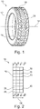
- the tire 10 as illustrated in Fig. 1 comprises a connecting part 12 be means of which the tire 10 can be connected to a tire rim auf a wheel of an automobile.
- the tire 10 is rotatable around a turning axis 14.
- the tire 10 comprises at its radial outer end a running surface 16 provided by a plurality of tire profiles 18 arranged at different regions of the outer curved surface area of the tire 10.
- the tire 10 is a directional tire. In the alternate the tire 10 may be a non-directional tire.
- the tire profile 18 may comprise a plurality of sipes 20 extending in a width direction 22 mainly parallel to the turning axis 14 and in a radial direction 24.
- Each sipe 20 provides a three-dimensional formed gab separating a first rubber block 26 from a second rubber block 28.
- the blocks 26, 28 provide the running surface 16 at its radial outer end.
- sipes 20 of the tire profile 18 are described.
- the sipes 20 and not the blocks 26, 28 are illustrated with hatchings.
- the illustrated appearance of the sipes 20 corresponds to sipe blades for use in a molding form for forming a tire 10 with the illustrated sipes 20. Further only a part of the tread portion of the tire profile 18 is illustrated.
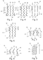
- the sipe 20 comprises a first part 30 inclined to the width direction 22 by an angle ⁇ 1 .
- a second part 32 inclined to the width direction 22 by an angle ⁇ 2 is connected to the first part 30 via a connecting line, wherein the second part 32 is inclined to the first part 30 by an angle ⁇ 1 .
- a third part 34 inclined to the width direction 22 by an angle ⁇ 3 is connected to the second part 32 via a connecting line, wherein the third part 34 is inclined to the second part 32 by an angle ⁇ 2 and so on.
- the connecting line between two adjacent parts 30, 32, 34 extends mainly in radial direction 24.
- the amplitude of the sipes 20 perpendicular to the width direction 22 may increase ( Fig. 4 ) and decrease ( Fig. 5 ) depending on the depth of the sipes 20 in radial direction 24.
- Even the orientation of the parts 30, 32, 34 may change.
- the angle ⁇ 1 of the first part 30 may have a positive mathematical value at the running surface 16 ( Fig. 3 ) and a negative mathematical value at a deeper position ( Fig. 4, Fig. 6 ), wherein a position in radial direction is present, where the angle ⁇ 1 is zero ( Fig. 5 ).
- the absolute value of angle ⁇ 1 at the top may be the same as at the bottom of the sipe 20 ( Fig. 6 ) but the sign of the mathematical value is different.
- the orientation of the other parts 32, 34 may change similarly so that not only the respective angle ⁇ but also the corresponding angle ⁇ changes continuously in radial direction 22.
- Each part 30, 32, 34 comprises at its radial outer end a first portion 36 inclined to the radial direction 24 by an angle ⁇ 1 .
- a second portion 38 inclined to the radial direction 24 by an angle ⁇ 2 is connected to the first portion 36 via a connecting line, wherein the second portion 38 is inclined to the first portion 36 by an angle ⁇ 1 .
- a third portion 40 inclined to the radial direction 24 by an angle ⁇ 3 is connected to the second portion 38 via a connecting line, wherein the third portion 40 is inclined to the second portion 38 by an angle ⁇ 2 and so on.
- the connecting line between two adjacent portions 36, 38, 40 extends mainly in width direction 22.
- the amplitude of the sipes 20 perpendicular to the radial direction 24 may change depending on the position in width direction 22 along the extension of the respective part 30, 32, 34 of the sipes 20. Even the orientation of the portions 36, 38, 40 may change.
- the angle ⁇ 1 of the first portion 36 may have a positive mathematical value at one connecting line between two adjacent part s 30, 32, 34 ( Fig. 7 ) and a negative mathematical value at the other connecting line of the respective part 30, 32, 34 ( Fig. 8 ), wherein a position in width direction of the respective part 30, 32, 34 is present, where the angle ⁇ 1 is zero.
- the absolute value of angle ⁇ 1 at the one connecting line Fig.
- the orientation of the other portions 38, 40 may change similarly so that not only the respective angle ⁇ but also the corresponding angle ⁇ changes continuously in width direction 24 along the respective part 30, 32, 34 of the sipe 20.
- the first portion 36 comprises a height h 1 in radial direction
- the second portion 38 comprises a height h 2 in radial direction
- the third portion 40 comprises a height h 3 in radial direction.
- the heights h remain constant in width direction 22, which means that the connecting lines between subsequent portions 36, 38, 40 stay at a particular height in radial direction 24.
- the irregular course, particularly zig-zag course, of the sipes 20 in width direction 22 as well as in radial direction 22 with continuously changing angles ⁇ and ⁇ leads to a three-dimensional shape surface of the blocks 26, 28.
- the blocks 26, 28 comprise a plurality of protrusions 42 and depressions 44 formed by the sipes 20, wherein the protrusions 42 and depressions 44 of two adjacent blocks 26, 28 points to each other. Due to the protrusions 42 and depressions 44 of the opposing blocks 26, 28 the blocks 26, 28 may easily engage with each other leading to an increased stiffness of the tire 10 comprising such kind of a tire profile 18.
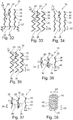
- the amplitude of the sipes 20 perpendicular to the width direction 22 is different along the extension of the sipe 20 in width direction 22.
- angle ⁇ 1 may be zero and angle ⁇ 3 different from zero at the top ( Fig. 10 ).
- angle ⁇ 1 is 180° and angle ⁇ 3 is different to 180°.
- the absolute value of angle ⁇ 1 increases and the absolute value of angle ⁇ 3 decreases from the running surface 16 radially inwards ( Fig.
- the part of sipe 20 with a straight course at the top may comprise a zig-zag cours at the bottom, wherein at the same time part of sipe 20 with a zig-zag course at the top may comprise a straigth cours at the bottom.
- the amplitude of the sipe 20 at one part may change from zero to its maximum amplitude, wherein the amplitude of the sipe 20 at another part may changes from its maximum amplitude to zero.
- the amplitude of the sipe 20 changes from its maximum amplitude to zero and further to the opposite site with a kind of "negative amplitude".
- the orientation of the parts 36, 38, 40 may change within the straight part of the sipe 20 as well as in the zig-zag part of the sipe 20.
- This means the angle ⁇ and/or the angle ⁇ may change continuously within a part 30, 32, 34 of the sipe 20.
- the sipe 20 may comprise a straight course over the whole extension in width direction at the top ( Fig. 18 ), wherein the amplitude of the sipes 20 perpendicular to the width direction 22 increases ( Fig. 19, Fig. 20 ) until the maximum amplitude is reached at the bottom forming a zig-zag course ( Fig. 21 ). Further it is possible, that the amplitude of the sipe 20 changes from its maximum amplitude to zero and further to the opposite site with a kind of "negative amplitude" in a direction radially inwards and/or radially outwards. Again, as illustrated in Fig. 22 and Fig.
- the orientation of the parts 36, 38, 40 may change within the respective part 30, 32, 34 of the sipe 20.
- the sipe 20 may comprise a zig-zag course over the whole extension in width direction at the top ( Fig. 25 ), wherein the amplitude of the sipes 20 perpendicular to the width direction 22 decreases ( Fig. 26, Fig. 27 ) until the amplitude is zero at the bottom forming a straight course ( Fig. 28 ). Further it is possible, that the amplitude of the sipe 20 changes from its maximum amplitude to zero and further to the opposite site with a kind of "negative amplitude" in a direction radially inwards and/or radially outwards. Again, as illustrated in Fig. 29 and Fig.
- the orientation of the parts 36, 38, 40 may change within the respective part 30, 32, 34 of the sipe 20.
- the sipes 20 may comprise a low amplitude perpendicular to the width direction 22 ( Fig. 32 ), which may increase to its maximum amplitude ( Fig. 33 ). From this position in radial direction 24 the amplitude may decrease until an amplitude corresponding to the amplitude at the top ( Fig. 34 ) and increasing again to its maximum amplitude at the bottom ( Fig. 35 ). In the alternate the amplitude of the sipes 20 perpendicular to the width direction 22 may be at its maximum at the top decrease to its minimum value above zero, increases again to its maximum value and decreases again to its minimum value at the bottom.
- the value of the low amplitude is higher than zero so that a straight part of the sipe 20 in width direction is avoided.
- the maximum value and the minimum vale of the amplitude is reached twice. However, it is possible that these values are reached more often or less, particularly the change between a decreasing and an increasing amount of the value of the amplitude may take place at different values of the amplitude.
- the amplitude of the sipes 20 perpendicular to the radial direction 24 may change depending on the position in width direction 22 along the extension of the respective part 30, 32, 34 of the sipes 20. Even the orientation of the portions 36, 38, 40 may change.
- the angle ⁇ 1 of the first portion 36 may have a positive mathematical value at one connecting line between two adjacent part s 30, 32, 34 ( Fig. 36 ) and a negative mathematical value at the other connecting line of the respective part 30, 32, 34 ( Fig. 37 ), wherein a position in width direction of the respective part 30, 32, 34 is present, where the angle ⁇ 1 is zero.
- the absolute value of angle ⁇ 1 at the one connecting line Fig.
- the orientation of the other portions 38, 40 may change similarly so that not only the respective angle ⁇ but also the corresponding angle ⁇ changes continuously in width direction 24 along the respective part 30, 32, 34 of the sipe 20. This means the angle ⁇ and/or the angle ⁇ may change continuously within a part 30, 32, 34 of the sipe 20.
- a pure zig-zag course or a pure straight course may be provided at the top.
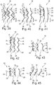
- the angles ⁇ 1 changes in a direction radially inwards such that the first part 30 and the second part 32 do not provide a zig-zag course but are oriented in the same direction perpendicular to the width direction 40 ( Fig. 40, Fig. 41 ).
- angles ⁇ 1 and ⁇ 2 comprise a different absolute vale but the same sign.
- angles ⁇ 2 and ⁇ 3 change its sign from the top to the bottom in radial direction 24 so that at the bottom a pure zig-zag course is provided ( Fig. 42 ).
- the sipes may comprise a course which is not a pure zig-zag course.
- the first portion 36, the second portion 38 and the third portion 40 may be arranged in a pure zig-zag course ( Fig. 43 ), wherein the angles ⁇ 1 , ⁇ 2 and ⁇ 3 change differently in width direction until a course is reached, where the mathematical value of angles ⁇ 1 and ⁇ 2 and/or the mathematical value of angles ⁇ 2 and ⁇ 3 , as illustrated in Fig. 45 , may comprise the same sign. From this position in width direction 22 the course may change back to a pure zig-zag course in radial direction 24 ( Fig. 44 ) and so on.
- the sipes 20 comprise a pure zig-zag course in width direction 22.
- the angles ⁇ 1 , ⁇ 2 and ⁇ 3 change differently in a direction radially inwards ( Fig. 47, Fig. 48 ) until the mathematical value of the angles ⁇ 1 and ⁇ 2 or the mathematical value of the angles ⁇ 2 and ⁇ 2 is the same ( Fig. 49 ).
- the second part 32 and the third part 34 are inclined to the width direction by the same angle so that ⁇ 2 is 180°.
- the second part 32 and the third part 34 are arranged in one line inclined to the width direction 22.
- the sipe 20 may comprise a doubled amplitude over a halved frequency in a part of the extension of the sipe in width direction 22 at the bottom or in the alternate at the top or between.
- the course of the sipe 20 in radial direction 24 may be a zig-zag course, wherein the angels ⁇ 1 , ⁇ 2 and ⁇ 3 as well as the angles ⁇ 1 , ⁇ 2 and ⁇ 3 change continuously in width direction 22.
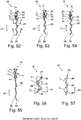
- the sipes 20 the sign of the mathematical value of the angels ⁇ 1 , ⁇ 2 and ⁇ 3 changes several times in radial direction 24 ( Fig. 52, Fig. 53, Fig. 54, Fig. 55 ).
- the amplitude of the sipe 20 in width direction may change continuously, particularly between a zig-zag course ( Fig. 56 ) and a mainly straight course ( Fig. 57 ).
- the sign of the mathematical value of the angels ⁇ 1 , ⁇ 2 and ⁇ 3 changes in width direction.
- Fig. 58 the behavior of the above mentioned embodiments of the tire profile 18 with respect to its stiffness is compared with a usual tire profile 18 comprising straight sipes with a straight course in radial direction 24 and width direction 22.
- a normalized longitudinal force 46 is shown over a displacement 48 in mm.
- the normalized force is the ratio of the applied forced to a given maximum force of 60 N.
- the illustrated curves are the results of a computer simulation of a box-shaped part of a tire profile 18 of 20 mm x 20 mm x 11 mm based on a nonlinear numerical simulation using a commercial FEA package.
- the block geometry of the tire profile 18 was meshed was meshed with finite elements.
- a base surface which attached to the tire profile 18 was fixed and pressed to a rigid flat road surface with a pressure of 0.25 MPa at the running surface 16.
- a constant coefficient of friction between the road surface and the tire profile 18 was assigned. Different tangential forces are applied to the tire profile and simulated which displacement takes place when road surface shears the simulated block geometry of the tire profile 18.
- the curve of "Sample 1" corresponds to the first embodiment of the tire profile 18 illustrated in Fig. 3 to 9 .
- the curve of "Sample 2" corresponds to the second embodiment of the tire profile 18 illustrated in Fig. 10 to 17 .
- the curve of "Sample 3" corresponds to the third embodiment of the tire profile 18 illustrated in Fig. 18 to 24 .
- the curve of "Sample 4" corresponds to the forth embodiment of the tire profile 18 illustrated in Fig. 25 to 31 .
- the curve of "Sample 5" corresponds to the fifth embodiment of the tire profile 18 illustrated in Fig. 31 to 38 .
- the curve of "Sample 6" corresponds to the sixth embodiment of the tire profile 18 illustrated in Fig. 39 to 45 .
- the curve of "Sample 7" corresponds to the sebenth embodiment of the tire profile 18 illustrated in Fig. 46 to 51 .
- the curve of "Sample 8" corresponds to the eigth embodiment of the tire profile 18 illustrated in Fig. 51 to 57 .
- the curve of "Straight sipe” corresponds to a tire profile according to the prior art comprising straight sipes with a straight course in radial direction 24 and width direction 22. It can derived from the diagram illustrated in Fig. 58 that particular at higher forces the tire profiles 18 according to the invention comprise a significant lower displacement leading to a higher stiffness at high loads. Hence, the tire profiles 18 according to the invention comprise a better grip than a tire profile with straight sipes.
Landscapes
- Engineering & Computer Science (AREA)
- Mechanical Engineering (AREA)
- Tires In General (AREA)
Claims (18)
- Profil de pneu d'un pneumatique (10) de véhicule automobile, ledit profil de pneu comprenant une bande de roulement comprenant au moins une incision lamelle (20), l'incision lamelle (20) comprenant une étendue dans la direction de la largeur (22) et une profondeur dans une direction radiale (24),
l'incision lamelle (20) comprenant une première portion (36), une deuxième portion (38) disposée radialement vers l'intérieur de la première portion (36) et au moins une portion supplémentaire (40), la portion supplémentaire (40) étant connectée à une portion disposée au-dessus de la portion supplémentaire (40) dans la direction radiale au niveau de leur ligne de connexion,
l'incision lamelle (20) comprenant une première partie (30), une deuxième partie (32) disposée directement à côté de la première partie (30) dans la direction de la largeur (22) et au moins une troisième partie (34) directement adjacente à la deuxième partie (32) dans la direction de la largeur (22),
caractérisé en ce que
la première partie (30) est inclinée par rapport à la direction de la largeur (22) suivant un angle aigu β1, la deuxième partie (32) est inclinée par rapport à la direction de la largeur (22) suivant un angle aigu β2 différent de β1 et la troisième partie (34) est inclinée par rapport à la direction de la largeur (22) suivant un angle aigu β3 différent de β1 et de β2, les valeurs mathématiques de β1 et de β2 étant toutes deux positives ou négatives le long d'au moins une partie de la direction radiale (24) et/ou les valeurs mathématiques de β2 et de βθ étant toutes deux positives ou négatives le long d'au moins une partie de la direction radiale (24),
la première partie (30) et la deuxième partie (32) étant inclinées l'une par rapport l'autre le long de leur ligne de connexion suivant un angle η1, la deuxième partie (32) et la troisième partie (34) étant inclinées l'une par rapport à l'autre le long de leur ligne de connexion suivant un angle n2, l'angle η1 et/ou l'angle η2 variant le long de la direction de la largeur (22) en continu dans une plage de 90° ≤ η1 ≤ 300° et/ou dans une plage de 90° ≤ η2 ≤ 300°. - Profil de pneu selon la revendication 1, dans lequel la première portion (36) est inclinée par rapport à la direction radiale (24) suivant un angle aigu α1, la deuxième portion (38) est inclinée par rapport à la direction radiale (24) suivant un angle aigu α2, différent de α1 et la portion supplémentaire (40) est inclinée par rapport à la direction radiale (24) suivant un angle aigu αx différent de α1 et différent de α2, les valeurs mathématiques de α1 et de α2 étant toutes deux positives ou négatives le long d'au moins une partie de la direction de la largeur (22) et/ou les valeurs mathématiques de α2 et de αx étant toutes deux positives ou négatives le long d'au moins une partie de la direction de la largeur (22).
- Profil de pneu selon la revendication 1 ou 2, dans lequel la première portion (36) et la deuxième portion (38) sont inclinées l'une par rapport à l'autre le long de leur ligne de connexion suivant un angle γ1 et la portion supplémentaire (40) est inclinée par rapport à la portion adjacente à la portion supplémentaire (40) suivant un angle γx, l'angle γ1 et/ou l'angle γx variant le long de la direction de la largeur (22) en continu.
- Profil de pneu selon la revendication 3, dans lequel une quantité de la variation de l'angle γ1 et d'au moins un angle γx dans la direction de la largeur (22) et/ou le signe de la variation de l'angle γ1 et d'au moins un angle γx le long de la direction de la largeur (22) sont différents.
- Profil de pneu selon la revendication 3 ou 4, dans lequel au moins un angle γ varie au moins le long d'une partie de l'extension de l'incision lamelle (20) dans la direction de la largeur (22) dans une plage de 40° ≤ γ ≤ 300°, en particulier de 90° ≤ γ ≤ 270°, de préférence de 135° ≤ γ ≤ 225° et/ou dans une plage de 40° ≤ γ ≤ 180°, en particulier de 90° ≤ γ ≤ 180°, de préférence de 135° ≤ γ ≤ 180°.
- Profil de pneu selon l'une quelconque des revendications 1 à 5, dans lequel les valeurs absolues d'un angle aigu au niveau de la ligne de connexion entre la première portion (36) et la deuxième portion (38) et d'un angle aigu au niveau de la ligne de connexion entre la deuxième portion (38) et la portion supplémentaire (40) sont différentes au niveau d'une position discrète dans la direction de la largeur (22).
- Profil de pneu selon l'une quelconque des revendications 1 à 6, dans lequel une pluralité de portions (36, 38, 40) disposées les unes derrière les autres dans la direction radiale sont prévues, une extrémité de chaque portion (36, 38, 40) étant disposée sur une ligne de base dans la direction radiale (24) et l'autre extrémité de chaque portion étant disposée de manière espacée d'une amplitude par rapport à la ligne de base, l'amplitude étant constante pour chaque portion (36, 38, 40) au niveau d'au moins une position discrète dans la direction de la largeur (22) et/ou l'amplitude étant différente pour différentes portions au moins en partie dans la direction de la largeur (22).
- Profil de pneu selon l'une quelconque des revendications 1 à 7, dans lequel une quantité de la variation de l'angle η1 et d'au moins un angle ηx dans la direction de la largeur (22) et/ou le signe de la variation de l'angle η1 et d'au moins un angle ηx dans la direction de la largeur (22) sont différents.
- Profil de pneu selon l'une quelconque des revendications 1 à 8, dans lequel les valeurs absolues d'un angle aigu au niveau de la ligne de connexion entre la première partie (30) et la deuxième partie (32) et d'un angle aigu au niveau de la ligne de connexion entre la deuxième partie (32) et la troisième partie (34) sont différentes au niveau d'une position discrète dans la direction radiale (24).
- Profil de pneu selon l'une quelconque des revendications 1 à 9, dans lequel une pluralité de parties (30, 32, 34) disposées les unes derrière les autres dans la direction de la largeur (22) sont prévues, une extrémité de chaque partie (30, 32, 34) étant disposée sur une ligne de base dans la direction de la largeur (22) et l'autre extrémité de chaque partie (30, 32, 34) étant disposée de manière espacée d'une amplitude par rapport à la ligne de base, l'amplitude étant constante pour chaque partie au niveau d'au moins une position discrète dans la direction radiale (24) et/ou l'amplitude étant différente pour différentes parties (30, 32, 34) au moins en partie dans la direction radiale (24).
- Profil de pneu selon l'une quelconque des revendications 1 à 10, dans lequel une pluralité de parties (30, 32, 34) disposées les unes derrière les autres dans la direction de la largeur (22) sont prévues, une extrémité de chaque partie (30, 32, 34) étant disposée sur une ligne de base dans la direction de la largeur (22) et l'autre extrémité de chaque partie (30, 32, 34) étant disposée de manière espacée d'une amplitude par rapport à la ligne de base, l'amplitude saillant, sur au moins une hauteur dans la direction radiale (24), dans une direction circonférentielle et sur au moins une autre hauteur dans la direction radiale (24), dans une direction circonférentielle opposée, pour au moins une partie des parties (30, 32, 34).
- Profil de pneu selon l'une quelconque des revendications 1 à 11, dans lequel l'incision lamelle (20) comprend une épaisseur d'espace essentiellement constante le long de la direction de la largeur (22) et le long de la direction radiale (24) dans un état non contraint.
- Profil de pneu selon l'une quelconque des revendications 1 à 12, dans lequel la première portion (36) comprend une hauteur h1 dans la direction radiale (24), la deuxième portion (38) comprend une hauteur h2 dans la direction radiale (24) et, le cas échéant, la portion supplémentaire (40) comprend une hauteur hx dans la direction radiale (24), les hauteurs h1, h2 et/ou hx étant essentiellement constantes le long de la direction de la largeur (22).
- Profil de pneu selon l'une quelconque des revendications 1 à 9, dans lequel la bande de roulement comprend un premier bloc (26) fournissant une première surface de roulement (16) au niveau de son extrémité radialement extérieure et un deuxième bloc (28) fournissant une deuxième surface de roulement (16) au niveau de son extrémité radialement extérieure, le premier bloc (26) étant disposé à distance du deuxième bloc (28) par l'incision lamelle (20), le premier bloc (26) formant un renfoncement (44) ouvert vers le deuxième bloc (28), le deuxième bloc (28) formant une saillie (42) faisant saillie en partie dans le renfoncement (44) du premier bloc (26).
- Pneumatique pour un véhicule automobile comprenant une partie de connexion prévue pour être connectée à une jante de pneu d'une roue du véhicule automobile et un profil de pneu (18) selon l'une quelconque des revendications 1 à 14 pour faire rouler le véhicule automobile le long d'une chaussée.
- Roue de véhicule automobile, ladite roue comprenant une jante de pneu prévue pour être connectée à un essieu du véhicule automobile et un pneumatique (10) selon la revendication 15, connecté à la jante de pneu.
- Lame d'incision lamelle pour un moule de moulage pour vulcaniser un pneu vert de manière à obtenir un pneu (10) comprenant un profil de pneu (18) selon l'une quelconque des revendications 1 à 14, ladite lame d'incision lamelle comprenant
une première portion de lame formant une première portion (36) d'une incision lamelle (20) s'étendant principalement dans la direction radiale (24) du pneu (10),
une deuxième portion de lame formant une deuxième portion (38) de l'incision lamelle (20), connectée à la première portion (36) radialement vers l'intérieur de la première portion (36),
une troisième portion de lame formant une portion supplémentaire (40) de l'incision lamelle (20), connectée à la première portion (36) radialement vers l'intérieur de la deuxième portion (38),
la première portion de lame, la deuxième portion de lame et la troisième portion de lame formant une première partie de lame formant une première partie (30) de l'incision lamelle (20) s'étendant principalement dans la direction de la largeur (22) du pneu (10),
une deuxième partie de lame formant une deuxième partie (32) de l'incision lamelle (20) s'étendant principalement dans la direction de la largeur (22), la deuxième partie de lame étant connectée à la première partie de lame, et
une troisième partie de lame formant une troisième partie (32) de l'incision lamelle (20) s'étendant principalement dans la direction de la largeur (22), la troisième partie de lame étant connectée à la deuxième partie de lame,
caractérisée en ce que
la première partie de lame est inclinée par rapport à la direction de la largeur (22) suivant un angle aigu β1', la deuxième partie de lame est inclinée par rapport à la direction de la largeur (22) suivant un angle aigu β2' différent de β1', et la troisième partie de lame est inclinée par rapport à la direction de la largeur (22) suivant un angle aigu β3' différent de β1' et de β2', les valeurs mathématiques de β1' et de β2' étant toutes deux positives ou négatives au moins en partie le long de la direction radiale (24) et/ou les valeurs mathématiques de β2' et de β3' étant toutes deux positives ou négatives au moins en partie le long de la direction radiale (24),
la première portion de lame et la deuxième portion de lame étant conçues de telle sorte que la première partie (30) et la deuxième partie (32) soient inclinées l'une par rapport à l'autre le long de leur ligne de connexion suivant un angle η1, que la deuxième partie (32) et la troisième partie (34) soient inclinées l'une par rapport à l'autre le long de leur ligne de connexion suivant un angle n2, l'angle η1 et/ou l'angle η2 variant le long de la direction de la largeur (22) en continu dans une plage de 90° ≤ η1 ≤ 300° et/ou dans une plage de 90° ≤ η2 ≤ 300°. - Moule de moulage pour vulcaniser un pneu vert de manière à obtenir un pneu (10), ledit moule de moulage comprenant un profil de pneu (18) selon l'une quelconque des revendications 1 à 14, comprenant un boîtier de moule pour recevoir un matériau à base de caoutchouc et
au moins une lame d'incision lamelle selon la revendication 17, faisant saillie radialement vers l'intérieur depuis le boîtier de moule, formant des incision lamelles (20) dans le matériau à base de caoutchouc.
Applications Claiming Priority (2)
| Application Number | Priority Date | Filing Date | Title |
|---|---|---|---|
| GBGB1408942.9A GB201408942D0 (en) | 2014-05-20 | 2014-05-20 | Tire profile and molding form |
| PCT/EP2015/059959 WO2015176958A1 (fr) | 2014-05-20 | 2015-05-06 | Profil de pneu et forme de moulage |
Publications (2)
| Publication Number | Publication Date |
|---|---|
| EP3145730A1 EP3145730A1 (fr) | 2017-03-29 |
| EP3145730B1 true EP3145730B1 (fr) | 2020-07-08 |
Family
ID=51135145
Family Applications (1)
| Application Number | Title | Priority Date | Filing Date |
|---|---|---|---|
| EP15720095.7A Active EP3145730B1 (fr) | 2014-05-20 | 2015-05-06 | Profil de pneu et forme de moulage |
Country Status (3)
| Country | Link |
|---|---|
| EP (1) | EP3145730B1 (fr) |
| GB (1) | GB201408942D0 (fr) |
| WO (1) | WO2015176958A1 (fr) |
Cited By (1)
| Publication number | Priority date | Publication date | Assignee | Title |
|---|---|---|---|---|
| US20240408919A1 (en) * | 2021-10-16 | 2024-12-12 | Bridgestone Americas Tire Operations, Llc | Directional interlocking sipe and/or slot |
Families Citing this family (4)
| Publication number | Priority date | Publication date | Assignee | Title |
|---|---|---|---|---|
| US12350970B2 (en) | 2017-10-30 | 2025-07-08 | Compagnie Generale Des Etablissements Michelin | Heavy truck tire tread and heavy truck tire |
| WO2019226168A1 (fr) * | 2018-05-24 | 2019-11-28 | Compagnie Generale Des Etablissements Michelin | Bande de roulement de pneu de poids lourd et pneu de poids lourd doté d'une lamelle d'épaulement inclinée et oblique |
| US11807045B2 (en) | 2021-06-14 | 2023-11-07 | The Goodyear Tire & Rubber Company | Tire with hybrid sipe pattern |
| DE102022213492A1 (de) * | 2022-12-12 | 2024-06-13 | Continental Reifen Deutschland Gmbh | Fahrzeugluftreifen |
Citations (1)
| Publication number | Priority date | Publication date | Assignee | Title |
|---|---|---|---|---|
| EP2821258A1 (fr) * | 2013-07-02 | 2015-01-07 | Kumho Tire Co., Inc. | Pneu |
Family Cites Families (3)
| Publication number | Priority date | Publication date | Assignee | Title |
|---|---|---|---|---|
| US6427737B1 (en) * | 1998-04-22 | 2002-08-06 | Bridgestone Corporation | Pneumatic tire having at least four sipes |
| JP4330455B2 (ja) * | 2004-01-09 | 2009-09-16 | 住友ゴム工業株式会社 | 空気入りタイヤ |
| WO2012001488A1 (fr) * | 2010-06-30 | 2012-01-05 | Pirelli Tyre S.P.A. | Pneu pour des roues de véhicule de transport de charge lourde |
-
2014
- 2014-05-20 GB GBGB1408942.9A patent/GB201408942D0/en not_active Ceased
-
2015
- 2015-05-06 WO PCT/EP2015/059959 patent/WO2015176958A1/fr not_active Ceased
- 2015-05-06 EP EP15720095.7A patent/EP3145730B1/fr active Active
Patent Citations (1)
| Publication number | Priority date | Publication date | Assignee | Title |
|---|---|---|---|---|
| EP2821258A1 (fr) * | 2013-07-02 | 2015-01-07 | Kumho Tire Co., Inc. | Pneu |
Cited By (2)
| Publication number | Priority date | Publication date | Assignee | Title |
|---|---|---|---|---|
| US20240408919A1 (en) * | 2021-10-16 | 2024-12-12 | Bridgestone Americas Tire Operations, Llc | Directional interlocking sipe and/or slot |
| US12623495B2 (en) * | 2021-10-16 | 2026-05-12 | Bridgestone Americas Tire Operations, Llc | Directional interlocking sipe and/or slot |
Also Published As
| Publication number | Publication date |
|---|---|
| WO2015176958A1 (fr) | 2015-11-26 |
| GB201408942D0 (en) | 2014-07-02 |
| EP3145730A1 (fr) | 2017-03-29 |
Similar Documents
| Publication | Publication Date | Title |
|---|---|---|
| CN101547799B (zh) | 包括双取向刀槽花纹的胎面 | |
| US10994575B2 (en) | Tire | |
| US10369846B2 (en) | Tread for heavy vehicle tire | |
| CN107031303B (zh) | 充气轮胎 | |
| EP2447093B1 (fr) | Chape de pneu | |
| US9616715B2 (en) | Tread for tire of a drive axle of a heavy goods vehicle and tire | |
| CN100569546C (zh) | 充气轮胎 | |
| US11667159B2 (en) | Tread for a pneumatic tire and a pneumatic tire | |
| EP2570271B1 (fr) | Bande de roulement de pneu à kilométrage élevé | |
| EP3335909B1 (fr) | Pneumatique, bande de roulement et bloc de bande de roulement comprenant une lamelle et plaque de lamelles pour sa fabrication | |
| CN102442163A (zh) | 加强轮胎胎面 | |
| CN104619524A (zh) | 重型车辆的胎面和轮胎 | |
| US10814676B2 (en) | Tread for heavy truck winter tire | |
| CN112399923B (zh) | 用于车辆车轮的轮胎 | |
| CN110248823B (zh) | 具有正向倾斜胎纹沟的改进的轮胎胎面 | |
| KR101296700B1 (ko) | 대형차량 타이어용 트레드 | |
| JP2014523366A (ja) | 幅広部分と幅狭部分を含む切込みを備えたトレッドを有するタイヤ | |
| WO2015176958A1 (fr) | Profil de pneu et forme de moulage | |
| CN104245360A (zh) | 充气轮胎 | |
| EP3444129A1 (fr) | Pneumatique | |
| EP2040940B1 (fr) | Bande de roulement et lamelle appropriée pour fixer dans un moule de vulcanisation pour former une lamelle coupée dans un bloc de bande de roulement | |
| EP3507106B1 (fr) | Bande de roulement de pneu de poids lourd et pneu de poids lourd | |
| CN104271366A (zh) | 车辆轮胎的运行条带轮廓 | |
| EP3145731B1 (fr) | Profil de pneu et forme de moulage | |
| JP6336999B2 (ja) | 方向性設計のタイヤトレッド |
Legal Events
| Date | Code | Title | Description |
|---|---|---|---|
| STAA | Information on the status of an ep patent application or granted ep patent |
Free format text: STATUS: THE INTERNATIONAL PUBLICATION HAS BEEN MADE |
|
| PUAI | Public reference made under article 153(3) epc to a published international application that has entered the european phase |
Free format text: ORIGINAL CODE: 0009012 |
|
| STAA | Information on the status of an ep patent application or granted ep patent |
Free format text: STATUS: REQUEST FOR EXAMINATION WAS MADE |
|
| 17P | Request for examination filed |
Effective date: 20161213 |
|
| AK | Designated contracting states |
Kind code of ref document: A1 Designated state(s): AL AT BE BG CH CY CZ DE DK EE ES FI FR GB GR HR HU IE IS IT LI LT LU LV MC MK MT NL NO PL PT RO RS SE SI SK SM TR |
|
| AX | Request for extension of the european patent |
Extension state: BA ME |
|
| DAV | Request for validation of the european patent (deleted) | ||
| DAX | Request for extension of the european patent (deleted) | ||
| STAA | Information on the status of an ep patent application or granted ep patent |
Free format text: STATUS: EXAMINATION IS IN PROGRESS |
|
| 17Q | First examination report despatched |
Effective date: 20181122 |
|
| RIC1 | Information provided on ipc code assigned before grant |
Ipc: B60C 11/12 20060101AFI20190910BHEP |
|
| GRAP | Despatch of communication of intention to grant a patent |
Free format text: ORIGINAL CODE: EPIDOSNIGR1 |
|
| STAA | Information on the status of an ep patent application or granted ep patent |
Free format text: STATUS: GRANT OF PATENT IS INTENDED |
|
| INTG | Intention to grant announced |
Effective date: 20191206 |
|
| GRAS | Grant fee paid |
Free format text: ORIGINAL CODE: EPIDOSNIGR3 |
|
| GRAA | (expected) grant |
Free format text: ORIGINAL CODE: 0009210 |
|
| STAA | Information on the status of an ep patent application or granted ep patent |
Free format text: STATUS: THE PATENT HAS BEEN GRANTED |
|
| AK | Designated contracting states |
Kind code of ref document: B1 Designated state(s): AL AT BE BG CH CY CZ DE DK EE ES FI FR GB GR HR HU IE IS IT LI LT LU LV MC MK MT NL NO PL PT RO RS SE SI SK SM TR |
|
| REG | Reference to a national code |
Ref country code: CH Ref legal event code: EP Ref country code: AT Ref legal event code: REF Ref document number: 1288066 Country of ref document: AT Kind code of ref document: T Effective date: 20200715 |
|
| REG | Reference to a national code |
Ref country code: DE Ref legal event code: R096 Ref document number: 602015055393 Country of ref document: DE |
|
| REG | Reference to a national code |
Ref country code: IE Ref legal event code: FG4D |
|
| REG | Reference to a national code |
Ref country code: NL Ref legal event code: FP |
|
| REG | Reference to a national code |
Ref country code: LT Ref legal event code: MG4D |
|
| REG | Reference to a national code |
Ref country code: AT Ref legal event code: MK05 Ref document number: 1288066 Country of ref document: AT Kind code of ref document: T Effective date: 20200708 |
|
| PG25 | Lapsed in a contracting state [announced via postgrant information from national office to epo] |
Ref country code: ES Free format text: LAPSE BECAUSE OF FAILURE TO SUBMIT A TRANSLATION OF THE DESCRIPTION OR TO PAY THE FEE WITHIN THE PRESCRIBED TIME-LIMIT Effective date: 20200708 Ref country code: NO Free format text: LAPSE BECAUSE OF FAILURE TO SUBMIT A TRANSLATION OF THE DESCRIPTION OR TO PAY THE FEE WITHIN THE PRESCRIBED TIME-LIMIT Effective date: 20201008 Ref country code: GR Free format text: LAPSE BECAUSE OF FAILURE TO SUBMIT A TRANSLATION OF THE DESCRIPTION OR TO PAY THE FEE WITHIN THE PRESCRIBED TIME-LIMIT Effective date: 20201009 Ref country code: BG Free format text: LAPSE BECAUSE OF FAILURE TO SUBMIT A TRANSLATION OF THE DESCRIPTION OR TO PAY THE FEE WITHIN THE PRESCRIBED TIME-LIMIT Effective date: 20201008 Ref country code: SE Free format text: LAPSE BECAUSE OF FAILURE TO SUBMIT A TRANSLATION OF THE DESCRIPTION OR TO PAY THE FEE WITHIN THE PRESCRIBED TIME-LIMIT Effective date: 20200708 Ref country code: HR Free format text: LAPSE BECAUSE OF FAILURE TO SUBMIT A TRANSLATION OF THE DESCRIPTION OR TO PAY THE FEE WITHIN THE PRESCRIBED TIME-LIMIT Effective date: 20200708 Ref country code: FI Free format text: LAPSE BECAUSE OF FAILURE TO SUBMIT A TRANSLATION OF THE DESCRIPTION OR TO PAY THE FEE WITHIN THE PRESCRIBED TIME-LIMIT Effective date: 20200708 Ref country code: LT Free format text: LAPSE BECAUSE OF FAILURE TO SUBMIT A TRANSLATION OF THE DESCRIPTION OR TO PAY THE FEE WITHIN THE PRESCRIBED TIME-LIMIT Effective date: 20200708 Ref country code: PT Free format text: LAPSE BECAUSE OF FAILURE TO SUBMIT A TRANSLATION OF THE DESCRIPTION OR TO PAY THE FEE WITHIN THE PRESCRIBED TIME-LIMIT Effective date: 20201109 Ref country code: AT Free format text: LAPSE BECAUSE OF FAILURE TO SUBMIT A TRANSLATION OF THE DESCRIPTION OR TO PAY THE FEE WITHIN THE PRESCRIBED TIME-LIMIT Effective date: 20200708 |
|
| PG25 | Lapsed in a contracting state [announced via postgrant information from national office to epo] |
Ref country code: PL Free format text: LAPSE BECAUSE OF FAILURE TO SUBMIT A TRANSLATION OF THE DESCRIPTION OR TO PAY THE FEE WITHIN THE PRESCRIBED TIME-LIMIT Effective date: 20200708 Ref country code: RS Free format text: LAPSE BECAUSE OF FAILURE TO SUBMIT A TRANSLATION OF THE DESCRIPTION OR TO PAY THE FEE WITHIN THE PRESCRIBED TIME-LIMIT Effective date: 20200708 Ref country code: LV Free format text: LAPSE BECAUSE OF FAILURE TO SUBMIT A TRANSLATION OF THE DESCRIPTION OR TO PAY THE FEE WITHIN THE PRESCRIBED TIME-LIMIT Effective date: 20200708 Ref country code: IS Free format text: LAPSE BECAUSE OF FAILURE TO SUBMIT A TRANSLATION OF THE DESCRIPTION OR TO PAY THE FEE WITHIN THE PRESCRIBED TIME-LIMIT Effective date: 20201108 |
|
| REG | Reference to a national code |
Ref country code: DE Ref legal event code: R097 Ref document number: 602015055393 Country of ref document: DE |
|
| PG25 | Lapsed in a contracting state [announced via postgrant information from national office to epo] |
Ref country code: EE Free format text: LAPSE BECAUSE OF FAILURE TO SUBMIT A TRANSLATION OF THE DESCRIPTION OR TO PAY THE FEE WITHIN THE PRESCRIBED TIME-LIMIT Effective date: 20200708 Ref country code: RO Free format text: LAPSE BECAUSE OF FAILURE TO SUBMIT A TRANSLATION OF THE DESCRIPTION OR TO PAY THE FEE WITHIN THE PRESCRIBED TIME-LIMIT Effective date: 20200708 Ref country code: SM Free format text: LAPSE BECAUSE OF FAILURE TO SUBMIT A TRANSLATION OF THE DESCRIPTION OR TO PAY THE FEE WITHIN THE PRESCRIBED TIME-LIMIT Effective date: 20200708 Ref country code: CZ Free format text: LAPSE BECAUSE OF FAILURE TO SUBMIT A TRANSLATION OF THE DESCRIPTION OR TO PAY THE FEE WITHIN THE PRESCRIBED TIME-LIMIT Effective date: 20200708 Ref country code: DK Free format text: LAPSE BECAUSE OF FAILURE TO SUBMIT A TRANSLATION OF THE DESCRIPTION OR TO PAY THE FEE WITHIN THE PRESCRIBED TIME-LIMIT Effective date: 20200708 |
|
| PLBE | No opposition filed within time limit |
Free format text: ORIGINAL CODE: 0009261 |
|
| STAA | Information on the status of an ep patent application or granted ep patent |
Free format text: STATUS: NO OPPOSITION FILED WITHIN TIME LIMIT |
|
| PG25 | Lapsed in a contracting state [announced via postgrant information from national office to epo] |
Ref country code: AL Free format text: LAPSE BECAUSE OF FAILURE TO SUBMIT A TRANSLATION OF THE DESCRIPTION OR TO PAY THE FEE WITHIN THE PRESCRIBED TIME-LIMIT Effective date: 20200708 |
|
| 26N | No opposition filed |
Effective date: 20210409 |
|
| PG25 | Lapsed in a contracting state [announced via postgrant information from national office to epo] |
Ref country code: SK Free format text: LAPSE BECAUSE OF FAILURE TO SUBMIT A TRANSLATION OF THE DESCRIPTION OR TO PAY THE FEE WITHIN THE PRESCRIBED TIME-LIMIT Effective date: 20200708 |
|
| PG25 | Lapsed in a contracting state [announced via postgrant information from national office to epo] |
Ref country code: SI Free format text: LAPSE BECAUSE OF FAILURE TO SUBMIT A TRANSLATION OF THE DESCRIPTION OR TO PAY THE FEE WITHIN THE PRESCRIBED TIME-LIMIT Effective date: 20200708 |
|
| REG | Reference to a national code |
Ref country code: CH Ref legal event code: PL |
|
| PG25 | Lapsed in a contracting state [announced via postgrant information from national office to epo] |
Ref country code: CH Free format text: LAPSE BECAUSE OF NON-PAYMENT OF DUE FEES Effective date: 20210531 Ref country code: LI Free format text: LAPSE BECAUSE OF NON-PAYMENT OF DUE FEES Effective date: 20210531 Ref country code: MC Free format text: LAPSE BECAUSE OF FAILURE TO SUBMIT A TRANSLATION OF THE DESCRIPTION OR TO PAY THE FEE WITHIN THE PRESCRIBED TIME-LIMIT Effective date: 20200708 Ref country code: LU Free format text: LAPSE BECAUSE OF NON-PAYMENT OF DUE FEES Effective date: 20210506 |
|
| REG | Reference to a national code |
Ref country code: BE Ref legal event code: MM Effective date: 20210531 |
|
| PG25 | Lapsed in a contracting state [announced via postgrant information from national office to epo] |
Ref country code: IE Free format text: LAPSE BECAUSE OF NON-PAYMENT OF DUE FEES Effective date: 20210506 |
|
| PG25 | Lapsed in a contracting state [announced via postgrant information from national office to epo] |
Ref country code: BE Free format text: LAPSE BECAUSE OF NON-PAYMENT OF DUE FEES Effective date: 20210531 |
|
| PG25 | Lapsed in a contracting state [announced via postgrant information from national office to epo] |
Ref country code: HU Free format text: LAPSE BECAUSE OF FAILURE TO SUBMIT A TRANSLATION OF THE DESCRIPTION OR TO PAY THE FEE WITHIN THE PRESCRIBED TIME-LIMIT; INVALID AB INITIO Effective date: 20150506 |
|
| PG25 | Lapsed in a contracting state [announced via postgrant information from national office to epo] |
Ref country code: CY Free format text: LAPSE BECAUSE OF FAILURE TO SUBMIT A TRANSLATION OF THE DESCRIPTION OR TO PAY THE FEE WITHIN THE PRESCRIBED TIME-LIMIT Effective date: 20200708 |
|
| P01 | Opt-out of the competence of the unified patent court (upc) registered |
Effective date: 20230621 |
|
| PG25 | Lapsed in a contracting state [announced via postgrant information from national office to epo] |
Ref country code: MK Free format text: LAPSE BECAUSE OF FAILURE TO SUBMIT A TRANSLATION OF THE DESCRIPTION OR TO PAY THE FEE WITHIN THE PRESCRIBED TIME-LIMIT Effective date: 20200708 |
|
| PGFP | Annual fee paid to national office [announced via postgrant information from national office to epo] |
Ref country code: NL Payment date: 20240521 Year of fee payment: 10 |
|
| PG25 | Lapsed in a contracting state [announced via postgrant information from national office to epo] |
Ref country code: MT Free format text: LAPSE BECAUSE OF FAILURE TO SUBMIT A TRANSLATION OF THE DESCRIPTION OR TO PAY THE FEE WITHIN THE PRESCRIBED TIME-LIMIT Effective date: 20200708 |
|
| PGFP | Annual fee paid to national office [announced via postgrant information from national office to epo] |
Ref country code: IT Payment date: 20240524 Year of fee payment: 10 |
|
| PGFP | Annual fee paid to national office [announced via postgrant information from national office to epo] |
Ref country code: DE Payment date: 20250527 Year of fee payment: 11 |
|
| PGFP | Annual fee paid to national office [announced via postgrant information from national office to epo] |
Ref country code: GB Payment date: 20250521 Year of fee payment: 11 |
|
| PGFP | Annual fee paid to national office [announced via postgrant information from national office to epo] |
Ref country code: FR Payment date: 20250528 Year of fee payment: 11 |
|
| PG25 | Lapsed in a contracting state [announced via postgrant information from national office to epo] |
Ref country code: TR Free format text: LAPSE BECAUSE OF FAILURE TO SUBMIT A TRANSLATION OF THE DESCRIPTION OR TO PAY THE FEE WITHIN THE PRESCRIBED TIME-LIMIT Effective date: 20200708 |
|
| REG | Reference to a national code |
Ref country code: NL Ref legal event code: MM Effective date: 20250601 |
|
| PG25 | Lapsed in a contracting state [announced via postgrant information from national office to epo] |
Ref country code: NL Free format text: LAPSE BECAUSE OF NON-PAYMENT OF DUE FEES Effective date: 20250601 |
|
| PG25 | Lapsed in a contracting state [announced via postgrant information from national office to epo] |
Ref country code: IT Free format text: LAPSE BECAUSE OF NON-PAYMENT OF DUE FEES Effective date: 20250506 |