EP3145745B1 - Fahrzeugmontierte hydraulische unterstützungsvorrichtung und verfahren zum leeren solch einer vorrichtung - Google Patents
Fahrzeugmontierte hydraulische unterstützungsvorrichtung und verfahren zum leeren solch einer vorrichtung Download PDFInfo
- Publication number
- EP3145745B1 EP3145745B1 EP16709423.4A EP16709423A EP3145745B1 EP 3145745 B1 EP3145745 B1 EP 3145745B1 EP 16709423 A EP16709423 A EP 16709423A EP 3145745 B1 EP3145745 B1 EP 3145745B1
- Authority
- EP
- European Patent Office
- Prior art keywords
- line
- booster
- pump
- pressure
- lines
- Prior art date
- Legal status (The legal status is an assumption and is not a legal conclusion. Google has not performed a legal analysis and makes no representation as to the accuracy of the status listed.)
- Not-in-force
Links
- 238000000034 method Methods 0.000 title claims description 6
- 238000004891 communication Methods 0.000 claims description 20
- 238000006073 displacement reaction Methods 0.000 claims description 16
- 230000004913 activation Effects 0.000 claims description 8
- 230000006837 decompression Effects 0.000 claims description 5
- 238000007789 sealing Methods 0.000 claims description 4
- 230000000903 blocking effect Effects 0.000 claims description 3
- 238000013022 venting Methods 0.000 claims 1
- 238000003304 gavage Methods 0.000 description 22
- 241000920340 Pion Species 0.000 description 6
- 238000010586 diagram Methods 0.000 description 6
- 230000008859 change Effects 0.000 description 5
- 230000001052 transient effect Effects 0.000 description 5
- 101000805943 Homo sapiens Usher syndrome type-1G protein Proteins 0.000 description 2
- 241001080024 Telles Species 0.000 description 2
- 102100037929 Usher syndrome type-1G protein Human genes 0.000 description 2
- 230000005540 biological transmission Effects 0.000 description 2
- 238000012840 feeding operation Methods 0.000 description 2
- 230000009467 reduction Effects 0.000 description 2
- 240000008042 Zea mays Species 0.000 description 1
- 230000003213 activating effect Effects 0.000 description 1
- 230000008878 coupling Effects 0.000 description 1
- 238000010168 coupling process Methods 0.000 description 1
- 238000005859 coupling reaction Methods 0.000 description 1
- 230000008569 process Effects 0.000 description 1
- 238000005096 rolling process Methods 0.000 description 1
- 230000002747 voluntary effect Effects 0.000 description 1
Images




Classifications
-
- B—PERFORMING OPERATIONS; TRANSPORTING
- B60—VEHICLES IN GENERAL
- B60K—ARRANGEMENT OR MOUNTING OF PROPULSION UNITS OR OF TRANSMISSIONS IN VEHICLES; ARRANGEMENT OR MOUNTING OF PLURAL DIVERSE PRIME-MOVERS IN VEHICLES; AUXILIARY DRIVES FOR VEHICLES; INSTRUMENTATION OR DASHBOARDS FOR VEHICLES; ARRANGEMENTS IN CONNECTION WITH COOLING, AIR INTAKE, GAS EXHAUST OR FUEL SUPPLY OF PROPULSION UNITS IN VEHICLES
- B60K17/00—Arrangement or mounting of transmissions in vehicles
- B60K17/04—Arrangement or mounting of transmissions in vehicles characterised by arrangement, location or kind of gearing
- B60K17/10—Arrangement or mounting of transmissions in vehicles characterised by arrangement, location or kind of gearing of fluid gearing
-
- B—PERFORMING OPERATIONS; TRANSPORTING
- B60—VEHICLES IN GENERAL
- B60K—ARRANGEMENT OR MOUNTING OF PROPULSION UNITS OR OF TRANSMISSIONS IN VEHICLES; ARRANGEMENT OR MOUNTING OF PLURAL DIVERSE PRIME-MOVERS IN VEHICLES; AUXILIARY DRIVES FOR VEHICLES; INSTRUMENTATION OR DASHBOARDS FOR VEHICLES; ARRANGEMENTS IN CONNECTION WITH COOLING, AIR INTAKE, GAS EXHAUST OR FUEL SUPPLY OF PROPULSION UNITS IN VEHICLES
- B60K17/00—Arrangement or mounting of transmissions in vehicles
- B60K17/34—Arrangement or mounting of transmissions in vehicles for driving both front and rear wheels, e.g. four wheel drive vehicles
- B60K17/354—Arrangement or mounting of transmissions in vehicles for driving both front and rear wheels, e.g. four wheel drive vehicles having separate mechanical assemblies for transmitting drive to the front or to the rear wheels or set of wheels
-
- B—PERFORMING OPERATIONS; TRANSPORTING
- B60—VEHICLES IN GENERAL
- B60K—ARRANGEMENT OR MOUNTING OF PROPULSION UNITS OR OF TRANSMISSIONS IN VEHICLES; ARRANGEMENT OR MOUNTING OF PLURAL DIVERSE PRIME-MOVERS IN VEHICLES; AUXILIARY DRIVES FOR VEHICLES; INSTRUMENTATION OR DASHBOARDS FOR VEHICLES; ARRANGEMENTS IN CONNECTION WITH COOLING, AIR INTAKE, GAS EXHAUST OR FUEL SUPPLY OF PROPULSION UNITS IN VEHICLES
- B60K17/00—Arrangement or mounting of transmissions in vehicles
- B60K17/34—Arrangement or mounting of transmissions in vehicles for driving both front and rear wheels, e.g. four wheel drive vehicles
- B60K17/356—Arrangement or mounting of transmissions in vehicles for driving both front and rear wheels, e.g. four wheel drive vehicles having fluid or electric motor, for driving one or more wheels
-
- F—MECHANICAL ENGINEERING; LIGHTING; HEATING; WEAPONS; BLASTING
- F16—ENGINEERING ELEMENTS AND UNITS; GENERAL MEASURES FOR PRODUCING AND MAINTAINING EFFECTIVE FUNCTIONING OF MACHINES OR INSTALLATIONS; THERMAL INSULATION IN GENERAL
- F16H—GEARING
- F16H39/00—Rotary fluid gearing using pumps and motors of the volumetric type, i.e. passing a predetermined volume of fluid per revolution
- F16H39/02—Rotary fluid gearing using pumps and motors of the volumetric type, i.e. passing a predetermined volume of fluid per revolution with liquid motors at a distance from liquid pumps
-
- F—MECHANICAL ENGINEERING; LIGHTING; HEATING; WEAPONS; BLASTING
- F16—ENGINEERING ELEMENTS AND UNITS; GENERAL MEASURES FOR PRODUCING AND MAINTAINING EFFECTIVE FUNCTIONING OF MACHINES OR INSTALLATIONS; THERMAL INSULATION IN GENERAL
- F16H—GEARING
- F16H61/00—Control functions within control units of change-speed- or reversing-gearings for conveying rotary motion ; Control of exclusively fluid gearing, friction gearing, gearings with endless flexible members or other particular types of gearing
- F16H61/38—Control of exclusively fluid gearing
- F16H61/40—Control of exclusively fluid gearing hydrostatic
- F16H61/4078—Fluid exchange between hydrostatic circuits and external sources or consumers
- F16H61/4104—Flushing, e.g. by using flushing valves or by connection to exhaust
-
- F—MECHANICAL ENGINEERING; LIGHTING; HEATING; WEAPONS; BLASTING
- F16—ENGINEERING ELEMENTS AND UNITS; GENERAL MEASURES FOR PRODUCING AND MAINTAINING EFFECTIVE FUNCTIONING OF MACHINES OR INSTALLATIONS; THERMAL INSULATION IN GENERAL
- F16H—GEARING
- F16H61/00—Control functions within control units of change-speed- or reversing-gearings for conveying rotary motion ; Control of exclusively fluid gearing, friction gearing, gearings with endless flexible members or other particular types of gearing
- F16H61/38—Control of exclusively fluid gearing
- F16H61/40—Control of exclusively fluid gearing hydrostatic
- F16H61/4078—Fluid exchange between hydrostatic circuits and external sources or consumers
- F16H61/4139—Replenishing or scavenging pumps, e.g. auxiliary charge pumps
Definitions
- the invention belongs to the field of hydraulic assistance on vehicles and in particular the engagement and disengagement of these assistances.
- Temporary hydraulic assistance is carried out using hydraulic machines which can supply torque to the mechanically non-motorized wheels. These machines transform the hydraulic energy of an oil under pressure into mechanical energy, or vice versa.
- Two phases of use are defined: the assistance phase which makes it possible to provide a gain in traction / torque and a freewheeling phase. Between these two phases there are two transient phases allowing the hydraulic assistance to be engaged or disengaged.
- the hydraulic circuits are pressurized by a booster pump. This pressure is used in particular to engage the motors.
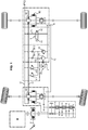
- the figure 1 details more precisely a hydraulic diagram of the prior art.
- a first hydraulic machine M1 is mounted on the front axle and a second hydraulic machine M2 is mounted on the rear axle.
- machines it means that they can operate as motors or pumps.
- the configuration presented corresponds to a "bicycle chain" (document FR 2 996 176 ), that is to say that in main use the first machine M1 acts as a pump for the second machine M2 which acts as a motor.
- the discharge of the first machine M1 is connected to the intake of the second machine M2 by a line 11 called high pressure and the discharge of the second machine M2 is connected to the intake of the first machine M1 by a line 12 known as low pressure.
- high and low pressure correspond to forward use with torque input ("main use"). Therefore, as the pressures can reverse, the terms first line 11 and second line 12 will be preferred.
- An electro-pump group P with in particular a booster pump P1 and an electric motor P2, is provided for the booster of lines 11, 12.
- the booster pump P1 can also be supplied by other elements, such as an axle or a heat engine M.
- a pressure limiter 20 is placed in bypass of the pump P1 to protect it from possible overpressures.
- the booster pump P1 supplies the first and second lines 11, 12 via a booster line 10, via two non-return valves B11, B12 which prevents the oil from being pumped back to the pump P1 when the booster pressure is lower. operating pressures.
- the oil comes from a drainage line 13 which is connected to one or more reservoirs R.
- two pressure limiters A11, A12 protect the first and second lines 11, 12 from overpressures by pouring oil into the booster line 10.
- the hydraulic circuit also has a vacuum valve V located on a vacuum line L.
- the vacuum line connects the first or second line 11, 12 (it is possible to put a selector between lines 11 and 12) to the drainage line 13 which leads to the reservoir R.
- Valve V is a 2/2 valve, comprising an inlet and an outlet.
- the inlet is connected to line 12 and the outlet to the drainage line 13.
- the valve V has a conducting state and a blocking state.
- the change to a blocking state is done using a solenoid slide V1 which is electrically controlled.
- This change of state causes a first transient phase by allowing the effective activation of the hydraulic assistance since the high and low pressure lines 11, 12 are then no longer connected to the tank R and can increase in pressure.
- This increase in pressure makes it possible to engage the couplers E1 and E2, which link the components of the hydraulic machines M1 and M2 to the output shafts of said machines, so as to make them active on the vehicle, that is to say d 'Engage the system.
- These couplers can be of the disc or dog clutch type, for example of the same type as the state of the art gearbox. They can also represent the coupling of radial piston motors which disengage from their cam by retraction of the pistons.
- a spring V2 maintains the valve V in the rest position in a passing state.
- the valve V resumes a passing position and causes a second transient phase, in which the pressure in the low pressure line V2 drops, thereby releasing the hydraulic assistance.
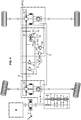
- the figure 2 shows a simplified alternative with a valve V 'which in the rest position opens the vacuum line L and blocks the booster line 10 and vice versa in the piloted position.
- This valve V ' is also electrically controlled by a solenoid.
- valves V, V ′ and the booster pump which imposes structural constraints and electrical networks.
- One of the objectives of the invention is to simplify the architectures currently existing by improving the performance of the device.
- the invention provides a device according to claim 1.
- the second transient phase is improved by accelerating the emptying of the first and second lines.
- the circulation in the opposite direction of the booster operation, of the flow through the pump, can be passive (pump shutdown and decompression of the lines) or active (pump control).
- a first aspect of the invention provides a device in which the pump is configured to suck in via the oil booster line from the first or second line, the oil being discharged towards the reservoir by said pump.
- this aspect of the invention proposes to use the booster pump to suck up the oil and thus promote disengagement.
- Activation of the suction line in suction takes place during a suitable period of time (depending on the oil volume and the characteristics of the pump).
- the disengagement phase which was hitherto passive (stopping the piloting of a valve with in particular shutdown of the booster pump) becomes active.
- the vacuum line can be removed, thereby simplifying the architecture.
- the device includes two hydraulic machines M1, M2 in bicycle chain operation, as mentioned in the introduction. These machines M1, M2 are interconnected by a first line 11 and a second line 12 and supply the machines with oil.
- the first machine M1 acts as a pump and the second machine M2 acts as the engine.
- the first line 11 connects the delivery of the first machine M1 to the intake of the second machine M2 and that the second line 12 connects the delivery of the second machine M2 to the intake of the first machine M1
- high pressure is meant pressures which may be greater than a few hundred bars, for example 400 bars and low pressure pressures of a few tens of Bar, for example 10 or 30 Bar.
- Low pressure differs from the pressure of pressureless oil tanks, for example represented by the housings of machines M1 and M2, and the pressureless tank R, substantially connected to pressure atmospheric.
- the low pressure pressure different from atmospheric pressure is in a known manner necessary for the proper functioning of a closed circuit transmission.
- a closed loop transmission has an HP line and a BP line. If no torque is produced by the machines, the two lines are at BP pressure, which is a minimum pressure for the closed circuit in operation.
- the pressures can also change along lines 11, 12.
- a booster circuit is provided to supply the lines 11, 12 with oil in order to allow the engagement of the machines M1, M2 and also to compensate for the oil leaks.
- This circuit makes it possible to maintain the lines to which it is connected at the minimum low pressure, called the booster pressure. Lines 11 and 12 are therefore always at least at the booster pressure when the system is activated.
- a booster pump 30, which will be called “pump 30" is provided. It is connected to reservoir R by a drainage line 13 and can supply the first and second lines 11, 12 via in particular a booster line 10.
- the booster pump 30 can deliver an oil under a pressure of a few tens of bar, substantially equivalent to the low pressure.
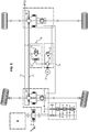
- the figure 3 shows a simplified diagram of the first aspect of the invention.
- the pump 30 is configured to be able to suck oil from the booster line 10 and in particular to discharge it to the reservoir R via the drainage line 13.
- the vacuum is thus done by reversing the operating direction of the pump 31 and there is no longer any need for a vacuum valve or for a specific vacuum line.
- the first and second lines 11, 12 each no longer include an independent check valve as before. In fact, the suction in the booster line 10 would lead to the locking of these non-return valves, which would prevent the oil from joining the booster line 10.
- the device When hydraulic assistance is required, the device operates conventionally, with an activation of the pump 30 to inject oil into the booster line 10 which will then pressurize the first and second lines 11, 12 and if necessary couplers E1, E2 for engaging machines M1, M2.
- the pump 30 reverses its direction of operation, that is to say that instead of taking oil from the reservoir R to inject it into the feeding line 10, it takes the oil in the first and / or second lines 11, 12 via the feeding line 10 and sends it to the reservoir R.
- the first and second lines 11, 12 are decompressed and the disengagement of the machines M1, M2 is carried out by the suction by the pump 30 of the necessary oil volume.
- the disengagement is carried out quickly thanks to the suction of the pump 30 which is considered to be more effective than a simple vacuum by opening a vacuum valve.
- the vacuum produces cavitations in the cylinders of hydraulic machines M1, M2.
- the decompression of the lower pressure line creates dead volumes under the pistons and due to the rotation of the machines M1, M2, the dead spaces are filled by the high pressure line, which allows the vacuum line of the higher pressure too.
- the M1 and M2 machines are running, one of them will take oil from the higher pressure line, towards the low pressure line, or it will be sucked in via the valve.
- the low pressure line is also emptied, so the pressure will drop in both lines at the same time.
- the invention allows on this particular circuit, to lower the pressure in the two lines, even if only one is connected directly to the pump.
- the expression “connected directly” must be understood to mean “without passing through another hydraulic machine” or “connected by a valve open to the line going towards the booster pump”. It is a voluntary cavitation process, caused in particular by the suction of the pump 30, which accelerates the vacuuming.
- the pump 30 is here supplied by an electric group 31, forming a GEP electric pump group.
- a pressure relief valve 20 is arranged in parallel with the pump 30, in a conventional manner.
- reversing the direction of rotation of the electric motor 31 makes the pump 30 work in the opposite direction.
- the speed, the duration of activation are a function of the volume of oil to be aspirated and of the characteristics of the device, such as the displacement. It is therefore necessary to have a GEP 30, 31 which can operate in both directions of rotation.
- the use of an electric group 31 is not specific to the first aspect, nor limiting.
- the booster line 10 is advantageously connected to the first and second lines 11, 12 by a low pressure selector 50 (in English terminology “ reverse shuttle valve “, or “reverse circuit selector”). This makes it possible to force-feed the line which always has the lowest pressure (when the vehicle is in reverse or in restraint, the pressures in lines 11, 12 can reverse).
- the selector 50 leaves the line of lowest pressure permanently open with the booster line 10.
- the low pressure selector 50 typically consists of two back-to-back non-return valves 51, 52, each comprising a sealing element, for example a ball, or a valve of a shape adapted to the flow rates and pressures of the system.
- a sealing element for the following we will consider for example and without this being limiting, a ball, 51a, 52a can be housed in a seat 51a, 51b respectively to close the passage of the oil.
- the balls 51a, 52a are kept at a minimum distance from each other by a rigid rod 53, so that one of the two valves 51, 52 is permanently open.
- the balls 51a, 52a can also be integral with the rigid rod 53. As soon as a pressure is greater on one side, the ball 51a, 52a is pressed against the seat 51b, 52b and closes the communication between the line 11, 12 and the booster line 10, thus freeing the opening of the other side between the other line 12, 11 and the booster line 10. For example on the figure 4 , the pressure is higher on the second line 12, which causes the closure of the valve 52 with the ball 52a, said ball 52a causing, thanks to the rod 53, the opening of the valve 51, thus putting the first line 11, lower pressure, with the booster line 10. There is an intermediate position where the three lines 10, 11, 12 are open.
- the figures 5 and 6 represent another valve 70 comprising both a pressure limiter 71 and a low pressure selector 72.
- the limiter 71 is a double limiter located between the first and second lines 11, 12. Overpressure in one of the two lines 11, 12 will be evacuated by pouring oil into the other line 12, 11.
- the valve 70 comprises a cartridge 701 in which there is a pin 711 and a pusher 721. The latter two can slide in relative translation along a longitudinal axis XX ′.
- the pusher 721 delimits the volume of the cartridge 701 in a first volume V1 supplied by the first line 11 and in a second volume V2 supplied by the second line 12.
- the two volumes V1, V2 are not completely independent and can communicate fluidly between them by an internal channel 722 which is included in the pusher 721.
- the pusher 721 defines with the cartridge 701 an annular volume Va between said pusher 721 and the cartridge 701. This annular volume Va is always in communication with the line of booster 10 and is alternately in communication with the first or second volume V1, V2. Thus, even when the booster pump 10 sucks, there is no risk of blockage.
- the pin 711 comprises a first end 711a which is adapted to obstruct the internal channel 722 in a rest position and to open it in a working position. These two positions are obtained by a translation of the pin 711 along X-X '. A second end 711b of said pin 711 is in contact with a spring 712 which maintains the pin 711 in the rest position.
- the pusher 72 when it is obstructed, has the function of low pressure selector 72.
- the pin 711 further comprises a first surface S1 opening into the first volume V1 on which a force is exerted from the pressure of the first volume V1.
- this first surface S1 corresponding to the surface obstructing the internal channel 722.
- the pin similarly comprises a second surface S2 opening into the second volume V2 and on which a force is exerted from the pressure of the second volume V2.
- this surface S2 is located between the volume V2 and a housing 713 of the spring 712.
- the two forces are exerted in the same direction and tend to put the pin 711 in the working position, that is to say to compress the spring 712 and to open the internal channel 722.
- the internal channel 722 opens and the two volumes V1, V2 communicate with each other to allow the overpressure to be discharged from a line 11, 12 towards the other 12, 11.
- the pin 711 and the spring 712 form the pressure relief valve 71. It is possible to obtain different calibrations between the first volume V1 and the second volume V2, by choosing suitable surfaces S1, S2. In practice, given the pressures involved (for example 400 bars in one line against 30 bars in the other), only one of the two volumes V1, V2 exerts a significant force against the spring 713.
- This valve 70 which incorporates a limiter 71 which acts with a single spring 713 and which incorporates a low pressure selector 72 allows better compactness of the device.
- a device is obtained whose engagement and disengagement of the machines M1, M2 is controlled solely by the booster pump 30 and the reversal of its direction of operation. It is no longer necessary to use electrically controlled valves.
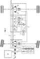
- the drawer 101 is hydraulically controlled by the booster line 10.
- the pump 30 is activated, which will put the booster line 10 under pressure.
- the drawer 101 is then piloted and the vacuum valve moves to the piloted position to allow the first and second lines 11, 12 to be force-fed.
- the pump 30 is activated in the opposite direction, which causes the oil to be sucked into the booster line 10 and will accelerate the setting in the rest position of the valve vacuum 100.
- the first and second lines 11, 12 are decompressed quickly and allow the machines M1, M2 to be disengaged.
- pressure limiters 81, 82 and non-return valves 91, 92 (in the direction passing from the booster line 10 to lines 11, 12) positioned in parallel between the first and second lines 11, 12 and the line booster 10 (when the vacuum valve 100 is in the piloted position).
- the vacuum line 14 is connected only to the line corresponding to the low pressure in forward gear and in torque addition mode. It is also possible to provide a low pressure selector which selects the line of lowest pressure between the first and second lines 11, 12 in order to connect it to the vacuum line 14. It is also possible to connect the two lines 11, 12 to the vacuum line 14.
- a device is obtained whose engagement and disengagement of the machines M1, M2 is controlled only by the booster pump 30 and the reversal of its operating direction.
- the disengagement of the hydraulic machines M1, M2 is effected by circulation in the opposite direction of the force-feeding operation, of the flow rate through the pump, typically by means of the suction of the pump. force-feeding 30.
- This circulation can be passive or active.
- Several types of pumps can be used. As a reminder, the previous figures represented a pump 30 driven by an electric motor 31 which can rotate in both directions, but this is in no way limiting.
- the figure 8 shows an embodiment in which the booster pump is a variable displacement pump 32. It is no longer necessarily necessary to have a pressure relief valve 20 in parallel.
- This known type of pump controls the displacement of the pump with respect to a pressure setpoint, via a retro-action line and a calibrated spring.
- This type of pump is equivalent to the juxtaposition of a fixed displacement pump and a pressure relief valve.
- the variable displacement pump 32 can be applied to all the embodiments described above.
- the figure 9 shows an embodiment in which the booster pump is a displacement pump 33.
- the pump 33 always rotates in the same direction but the change of displacement to a negative displacement will cause the suction.
- the general principle of the embodiments described remains the same.
- FIG 9 independently of the displacement version 33 pump, an architecture in which the pump is driven by an axle of the vehicle (if necessary with a reduction gear and a coupler, for example of the disc clutch type).
- This alternative nevertheless mainly concerns pump 33 since it would otherwise have to incorporate a rotation reverser between the axle and the pump in order to be able to cause suction.
- the pump can also be rotated by the heat engine M directly.
- a casing (not shown) protects the assembly.
- the casing can act as a reservoir R.
- the reservoir R is substantially at atmospheric pressure. It can be connected to it via breather pipes, filters, or valves, which can create a very slight pressure difference compared to the outside.
Landscapes
- Engineering & Computer Science (AREA)
- Mechanical Engineering (AREA)
- General Engineering & Computer Science (AREA)
- Chemical & Material Sciences (AREA)
- Combustion & Propulsion (AREA)
- Transportation (AREA)
- Fluid-Pressure Circuits (AREA)
- Motor Power Transmission Devices (AREA)
- Arrangement And Driving Of Transmission Devices (AREA)
- Control Of Fluid Gearings (AREA)
Claims (15)
- Vorrichtung, umfassend:- eine erste hydraulische Maschine (M1), die als Motor oder als Pumpe arbeiten kann, und eine zweite hydraulische Maschine (M2), die als Motor oder als Pumpe arbeiten kann, wobei die zwei hydraulischen Maschinen (M1, M2) durch eine erste Leitung (11) und eine zweite Leitung (12) verbunden sind, die den Zufluss oder den Abfluss von Öl in den hydraulischen Maschinen (M1, M2) erlauben,- eine Speisepumpe (30, 32, 33), die zwischen einem Vorratsbehälter (R) und einer Speiseleitung (10) angeordnet ist, wobei die Speiseleitung (10) in Kommunikation mit mindestens einer der Leitungen (11, 12) ist und die Versorgung der Leitungen (11, 12) durch die Speisepumpe (30) erlauben kann,dadurch gekennzeichnet, dass:- die zwei hydraulischen Maschinen (M1, M2) dank Kopplern (E1, E2), die von der ersten und zweiten Leitung (11, 12) hydraulisch versorgt werden, in Eingriff bringbar sind,- die Speisepumpe (30, 32, 33) konfiguriert ist, um Öl in die Speiseleitung (10) ansaugen zu können, um die Dekompression der ersten und zweiten Leitung (11, 12) zu erlauben.
- Vorrichtung nach Anspruch 1, wobei die Speisepumpe (30, 32, 33) konfiguriert ist, um über die Speiseleitung (10) Öl aus der ersten oder der zweiten Leitung (11, 12) ansaugen zu können, wobei das Öl von der Speisepumpe (30) zum Vorratsbehälter (R) zurückgepumpt wird.
- Vorrichtung nach Anspruch 2, umfassend ferner ein Niederdruckwechselventil (50, 60, 72) zwischen der ersten und zweiten Leitung (11, 12) und verbunden mit der Speiseleitung (10), wobei das Wechselventil (50, 60, 72) die Leitung mit dem niedrigeren Druck zwischen der ersten und zweiten Leitung (11 ,12) wählt, so dass das in vorteilhafter Weise in die Leitung mit niedrigerem Druck angesaugte und zum Vorratsbehälter (R) dank der Pumpe (30, 32, 33) geförderte Öl durch die Speiseleitung und die Speisepumpe in umgekehrter Richtung zum Speisebetrieb zirkulieren und sich im Vorratsbehälter entspannen kann.
- Vorrichtung nach Anspruch 3, wobei Druckbegrenzer (41, 42, 72) parallel zum Wechselventil (50, 60, 72) zwischen der Speiseleitung (13) und der ersten und zweiten Leitung (11, 12) derart angeordnet sind, dass diese beiden Letztgenannten (11, 12) vor Überdruck geschützt sind.
- Vorrichtung nach einem der Ansprüche 3 oder 4, wobei das Niederdruckwechselventil ein Inverskreiswechselventil ist, das immer die Leitung (11, 12) mit dem niedrigeren Druck von der ersten und zweiten Leitung (11, 12) in Kommunikation mit der Speiseleitung (10) lässt.
- Vorrichtung nach Anspruch 5, wobei das Niederdruckwechselventil (50, 60, 70) zwei Rückflusssperrklappe (51, 52) Rücken an Rücken umfasst, umfassend jeweils ein Dichtungselement, beispielsweise eine Kugel, (51a, 52a) und einen Sitz (51b, 52b), wobei die beispielsweise von Kugeln (51a, 52a) gebildeten Abdichtungen durch eine Stange (53) voneinander getrennt sind, die verhindert, dass die zwei Ventile (51, 52) gleichzeitig geschlossen sind.
- Vorrichtung nach Anspruch 6, wobei das Niederdruckwechselventil einen Druckbegrenzer parallel zu jeder Rückflusssperrklappe umfasst, wobei das Wechselventil und die Klappen zu ein- und demselben Ventil (60) gehören.
- Vorrichtung nach einem der Ansprüche 3 bis 6, wobei das Niederdruckwechselventil und die Druckbegrenzer (71) von einem einzigen Ventil (70) gebildet sind, wobei das Ventil eine Kartusche (701) umfasst, in welcher ein Stößel (721) und ein Stift (711) gemäß der Längsachse X-X' des Ventils (70) gleiten kann, wobei:- der Stößel (721) die Kartusche (701) in ein erstes Volumen (V11), versorgt durch die erste Leitung (11), und in ein zweites Volumen (V12), versorgt durch die zweite Leitung (12), trennt, wobei die zwei Volumen (V11, V12) miteinander durch einen inneren Kanal (722) kommunizieren können, der in dem Stößel enthalten ist,- der Stößel (721) ein ringförmiges Volumen (Va) mit der Kartusche (701) definiert, wobei das ringförmige Volumen (Va) abwechselnd mit dem ersten oder dem zweiten Volumen (V11, V12) je nach translatorischer Position des Stößels (721) in der Kartusche (701) gemäß der Längsachse (X- X') kommuniziert,- der Stift (711) ein erstes Ende (711a), das zum Verschließen des Kanals (722) in einer Ruhestellung geeignet ist, und ein zweites Ende (711b) im Kontakt mit einer Feder (712), die den Stift (711) in Ruhestellung hält, umfasst, wobei der Stift (711) gemäß der Längsachse (X-X') translatorisch beweglich ist, um den inneren Kanal (722) zu öffnen oder zu verschließen,
so dass, wenn der Kanal verschlossen ist, die Position des Stößels (721) von den Kräften abhängt, die von den Drücken des ersten Volumens (VI) und des zweiten Volumens (V2) ausgehen, die beiderseits des Stößels (721) ausgeübt werden, und die Speiseleitung (10) somit mit der Leitung (11, 12) in Kommunikation versetzt wird, die den niedrigeren Druck von der ersten und zweiten Leitung (11, 12) hat,- der Stift (711) eine erste Fläche (Sl), die in das erste Volumen (V1) ausmündet, auf die eine Kraft ausgeübt wird, die vom Druck des ersten Volumens (V1) ausgeht, und eine zweite Fläche (S2), die in das zweite Volumen (V2) ausmündet, auf die eine Kraft ausgeübt wird, die vom Druck des zweiten Volumens (V2) ausgeht, umfasst, wobei die zwei Kräfte beide der Kraft der Feder (712) entgegenwirken,
so dass, wenn die beiden Kräfte größer als die der Feder (712) sind, der Stift (711) eine Translation erfährt und den Kanal (722) öffnet, wodurch die Hoch- und Niederdruckleitung (11, 12) in Kommunikation versetzt werden. - Vorrichtung nach Anspruch 1, umfassend ferner ein Entlastungsventil (100) mit einem Steuerschieber (101) und eine Entlastungsleitung (14), wobei das Ventil besitzt:- eine nicht gesteuerte Ruhestellung, in welcher:wobei der Steuerschieber (101) von dem Druck der Speiseleitung (10) derart gesteuert wird, dass das Ventil (101) von der Speisepumpe (30) hydraulisch gesteuert wird und dass das Ansaugen von Öl in die Speiseleitung (10) durch die Speisepumpe (30) bewirkt, dass das Entlastungsventil (101) in Ruhestellung versetzt wird, was die Druckentlastung der ersten und zweiten Leitung (11, 12) erlaubt.- die erste Leitung (11), die zweite Leitung (12) oder ein Leitungs-Wechselventil, das diejenige von der ersten Leitung (11) oder der zweiten Leitung (12) mit höherem Druck wählt, über die Entlastungsleitung (14) mit dem Vorratsbehälter (R) verbunden ist,- die Speiseleitung (10) geschlossen ist,- eine gesteuerte Position, in welcher:- die Speiseleitung (10) mit der Hochdruckleitung (11) oder der Niederdruckleitung (12) verbunden ist,- die Entlastungsleitung (14) geschlossen ist,
- Vorrichtung nach Anspruch 9, wobei das Entlastungsventil (100) eine dichte Übergangsposition umfasst, die jede Kommunikation zwischen der Hoch- und Niederdruckleitung (11, 12) zum einen und der Speiseleitung (10) und dem Vorratsbehälter (R) zum anderen verhindert.
- Vorrichtung nach einem der Ansprüche 1 bis 10, wobei das Ansaugen durch Umkehren der Rotationsrichtung der Speisepumpe (30) erfolgt.
- Vorrichtung nach einem der Ansprüche 1 bis 11, wobei die Speisepumpe eine Hubraumumkehrpumpe (33) ist, so dass das Ansaugen durch negativen Hubraum und nicht durch Umkehren der Rotationsrichtung der Pumpe erfolgt.
- Verfahren zum Entlasten einer Vorrichtung nach einem der vorangehenden Ansprüche, wobei die Speisepumpe (30) in der Speiseleitung (10) ansaugend aktiviert ist, um das Trennen der Maschinen (M1, M2) zu erlauben.
- Verfahren nach vorangehendem Anspruch mit Hilfe einer Vorrichtung nach Anspruch 11, wobei die ansaugende Aktivierung der Speisepumpe (30) durch Umkehren der Rotationsrichtung eines Elektromotors erfolgt, der die Pumpe (30) antreibt.
- Verfahren nach Anspruch 13 mit Hilfe einer Vorrichtung nach Anspruch 12, wobei die ansaugende Aktivierung der Speisepumpe (30) durch Umkehren des Hubraums der Speisepumpe (30) erfolgt, ohne dass sich ihre Rotationsrichtung ändert.
Priority Applications (1)
| Application Number | Priority Date | Filing Date | Title |
|---|---|---|---|
| EP16205571.9A EP3189998B1 (de) | 2015-03-13 | 2016-03-10 | Hydraulische vorrichtung, die einen niedrigdruck-wahlschalter umfasst und fahrzeug, das eine solche vorrichtung umfasst |
Applications Claiming Priority (2)
| Application Number | Priority Date | Filing Date | Title |
|---|---|---|---|
| FR1500495A FR3033529B1 (fr) | 2015-03-13 | 2015-03-13 | Dispositif d'assistance hydraulique sur vehicule et procede de mise a vide d'un tel dispositif |
| PCT/EP2016/055192 WO2016146489A1 (fr) | 2015-03-13 | 2016-03-10 | Dispositif d'assistance hydraulique sur véhicule et procédé de mise à vide d'un tel dispositif |
Related Child Applications (2)
| Application Number | Title | Priority Date | Filing Date |
|---|---|---|---|
| EP16205571.9A Division EP3189998B1 (de) | 2015-03-13 | 2016-03-10 | Hydraulische vorrichtung, die einen niedrigdruck-wahlschalter umfasst und fahrzeug, das eine solche vorrichtung umfasst |
| EP16205571.9A Division-Into EP3189998B1 (de) | 2015-03-13 | 2016-03-10 | Hydraulische vorrichtung, die einen niedrigdruck-wahlschalter umfasst und fahrzeug, das eine solche vorrichtung umfasst |
Publications (2)
| Publication Number | Publication Date |
|---|---|
| EP3145745A1 EP3145745A1 (de) | 2017-03-29 |
| EP3145745B1 true EP3145745B1 (de) | 2020-05-06 |
Family
ID=53059224
Family Applications (2)
| Application Number | Title | Priority Date | Filing Date |
|---|---|---|---|
| EP16205571.9A Not-in-force EP3189998B1 (de) | 2015-03-13 | 2016-03-10 | Hydraulische vorrichtung, die einen niedrigdruck-wahlschalter umfasst und fahrzeug, das eine solche vorrichtung umfasst |
| EP16709423.4A Not-in-force EP3145745B1 (de) | 2015-03-13 | 2016-03-10 | Fahrzeugmontierte hydraulische unterstützungsvorrichtung und verfahren zum leeren solch einer vorrichtung |
Family Applications Before (1)
| Application Number | Title | Priority Date | Filing Date |
|---|---|---|---|
| EP16205571.9A Not-in-force EP3189998B1 (de) | 2015-03-13 | 2016-03-10 | Hydraulische vorrichtung, die einen niedrigdruck-wahlschalter umfasst und fahrzeug, das eine solche vorrichtung umfasst |
Country Status (8)
| Country | Link |
|---|---|
| US (1) | US10406914B2 (de) |
| EP (2) | EP3189998B1 (de) |
| JP (1) | JP6715268B2 (de) |
| CN (1) | CN107532711B (de) |
| BR (1) | BR112017019473A2 (de) |
| FR (1) | FR3033529B1 (de) |
| RU (1) | RU2710124C2 (de) |
| WO (1) | WO2016146489A1 (de) |
Families Citing this family (12)
| Publication number | Priority date | Publication date | Assignee | Title |
|---|---|---|---|---|
| FR3072148B1 (fr) | 2017-10-09 | 2019-10-18 | Poclain Hydraulics Industrie | Procede et systeme d'auto-maintenance |
| FR3072065B1 (fr) | 2017-10-09 | 2019-10-18 | Poclain Hydraulics Industrie | Balayage de fluide hyraulique au demarrage |
| FR3075732B1 (fr) | 2017-12-21 | 2019-12-20 | Poclain Hydraulics Industrie | Vehicule comprenant un dispositif de mise a l'arret controle du moteur principal et un dispositif d'assistance a l'entrainement |
| US20190193558A1 (en) * | 2017-12-22 | 2019-06-27 | Caterpillar Inc. | System for providing torque assist in a vehicle |
| FR3075911B1 (fr) * | 2017-12-22 | 2021-12-10 | Poclain Hydraulics Ind | Systeme et procede de detection de fuite dans un circuit hydraulique |
| CN112020528B (zh) | 2018-03-15 | 2022-08-30 | 科思创知识产权两合公司 | 储存稳定、含颜料且含异氰酸酯基团的配制品及其用途 |
| FR3079192B1 (fr) | 2018-03-26 | 2020-03-27 | Poclain Hydraulics Industrie | Vehicule equipe d'un systeme hydraulique d'assistance a l'entrainement et systeme hydraulique d'assistance prevu a cette fin |
| ES1218514Y (es) * | 2018-04-04 | 2018-12-27 | Sotavento Cafe Sl | Sistema de propulsion hidraulico para vehiculos de doble traccion |
| FR3083839B1 (fr) * | 2018-07-16 | 2020-10-23 | Poclain Hydraulics Ind | Circuit d'assistance hydraulique comprenant des moyens de gavage ameliores |
| DE102018124014A1 (de) * | 2018-09-28 | 2020-04-02 | Man Truck & Bus Se | Kraftfahrzeug mit einem Hilfsantrieb für eine lenkbare Achse |
| CN109720198B (zh) * | 2019-01-16 | 2022-02-15 | 江苏大学 | 一种静液压驱动双轴的多功能变速传动装置 |
| FR3138485B1 (fr) * | 2022-09-22 | 2026-08-07 | Poclain Hydraulics Ind | Transmission hydrostatique améliorée. |
Family Cites Families (22)
| Publication number | Priority date | Publication date | Assignee | Title |
|---|---|---|---|---|
| US2961829A (en) | 1959-10-15 | 1960-11-29 | New York Air Brake Co | Hydraulic transmission |
| DE2246638A1 (de) * | 1972-09-22 | 1974-04-04 | Bosch Gmbh Robert | Hydrostatisches getriebe |
| US4244184A (en) * | 1979-08-23 | 1981-01-13 | Paul Revere Corporation | Auxiliary hydrostatic drive system |
| EP0059485A1 (de) * | 1981-03-04 | 1982-09-08 | Eaton Corporation | Ventil zur Leistungsabschaltung für ein hydrostatisches Getriebe |
| SU1035909A1 (ru) * | 1981-08-14 | 1985-05-15 | Всесоюзный Ордена Трудового Красного Знамени Научно-Исследовательский Институт Механизации Сельского Хозяйства | Транспортное средство с гидроприводом направл ющих колес |
| US4696162A (en) | 1984-05-09 | 1987-09-29 | Sundstrand Corporation | Multi-function valve |
| JPS62292958A (ja) * | 1986-06-11 | 1987-12-19 | Shimadzu Corp | 液圧システム |
| US5271722A (en) * | 1993-01-11 | 1993-12-21 | Sauer Inc. | Automotive control system for hydrostatic pumps |
| JP4000427B2 (ja) * | 1997-06-23 | 2007-10-31 | 株式会社 神崎高級工機製作所 | 油圧伝動装置 |
| US6837047B2 (en) * | 2002-07-12 | 2005-01-04 | Parker-Hannifin Corporation | Hydraulic devices for smooth operations of hydrostatic transmission |
| US6698197B1 (en) * | 2002-11-26 | 2004-03-02 | Eaton Corporation | Hydraulically actuated by-pass valve |
| US6964163B2 (en) * | 2003-11-10 | 2005-11-15 | Sauer-Danfoss, Inc. | Dual check-relief valve |
| US6993904B2 (en) | 2004-05-06 | 2006-02-07 | Eaton Corporation | Integrated valve system |
| RU2280796C1 (ru) * | 2005-01-26 | 2006-07-27 | Открытое акционерное общество "Инновационная фирма "НАМИ-СЕРВИС" | Гидрообъемная трансмиссия с управляемой фрикционной муфтой привода насосной станции |
| US20110240897A1 (en) | 2008-10-08 | 2011-10-06 | Robert Bosch Gmbh | Pressure Limiting And Suction Valve Unit |
| DE102009011247A1 (de) * | 2009-03-02 | 2010-09-09 | Robert Bosch Gmbh | Hydrostatischer Antrieb |
| JP4875122B2 (ja) * | 2009-09-02 | 2012-02-15 | 株式会社シー・オー・シー | 艦船用バルブ駆動ユニット |
| ITBO20110599A1 (it) | 2011-10-21 | 2013-04-22 | S T S R L | Valvola oleo-idraulica |
| FR2996176B1 (fr) * | 2012-09-28 | 2015-08-07 | Poclain Hydraulics Ind | Vehicule a assistance hydraulique par transmission du couple d'un essieu menant vers un essieu mene |
| DE102013114038A1 (de) * | 2013-12-13 | 2015-06-18 | Linde Hydraulics Gmbh & Co. Kg | Hydrostatischer Antrieb im geschlossenen Kreislauf |
| FR3019612B1 (fr) * | 2014-04-02 | 2016-04-08 | Poclain Hydraulics Ind | Systeme d'assistance hydraulique |
| FR3029587B1 (fr) * | 2014-12-04 | 2018-12-07 | Technoboost | Circuit hydraulique comprenant un drain de machine hydraulique equipe d’un moyen de controle du debit et des fonctions de traitement de fluide |
-
2015
- 2015-03-13 FR FR1500495A patent/FR3033529B1/fr not_active Expired - Fee Related
-
2016
- 2016-03-10 CN CN201680022935.7A patent/CN107532711B/zh not_active Expired - Fee Related
- 2016-03-10 WO PCT/EP2016/055192 patent/WO2016146489A1/fr not_active Ceased
- 2016-03-10 BR BR112017019473-2A patent/BR112017019473A2/pt active Search and Examination
- 2016-03-10 EP EP16205571.9A patent/EP3189998B1/de not_active Not-in-force
- 2016-03-10 US US15/557,743 patent/US10406914B2/en not_active Expired - Fee Related
- 2016-03-10 EP EP16709423.4A patent/EP3145745B1/de not_active Not-in-force
- 2016-03-10 JP JP2017566201A patent/JP6715268B2/ja not_active Expired - Fee Related
- 2016-03-10 RU RU2017132417A patent/RU2710124C2/ru active
Non-Patent Citations (1)
| Title |
|---|
| None * |
Also Published As
| Publication number | Publication date |
|---|---|
| FR3033529B1 (fr) | 2018-05-18 |
| WO2016146489A1 (fr) | 2016-09-22 |
| US10406914B2 (en) | 2019-09-10 |
| EP3189998B1 (de) | 2020-07-29 |
| CN107532711B (zh) | 2019-09-03 |
| RU2017132417A3 (de) | 2019-07-24 |
| FR3033529A1 (fr) | 2016-09-16 |
| EP3189998A1 (de) | 2017-07-12 |
| JP6715268B2 (ja) | 2020-07-01 |
| BR112017019473A2 (pt) | 2018-05-15 |
| JP2018511017A (ja) | 2018-04-19 |
| CN107532711A (zh) | 2018-01-02 |
| US20180065479A1 (en) | 2018-03-08 |
| EP3145745A1 (de) | 2017-03-29 |
| RU2017132417A (ru) | 2019-04-15 |
| RU2710124C2 (ru) | 2019-12-24 |
Similar Documents
| Publication | Publication Date | Title |
|---|---|---|
| EP3189998B1 (de) | Hydraulische vorrichtung, die einen niedrigdruck-wahlschalter umfasst und fahrzeug, das eine solche vorrichtung umfasst | |
| EP2901014B1 (de) | Hydraulische vorrichtung mit einer verbesserten struktur zur zylinderimplementierung dafür | |
| FR3019612A1 (fr) | Systeme d'assistance hydraulique | |
| EP3002484B1 (de) | Ölverteilungsvorrichtung mit rückschlagventil | |
| EP3268638B1 (de) | Verteilervorrichtung und druckbegrenzer, insbesondere für eine hydraulische stützvorrichtung auf einem fahrzeug und fahrzeug damit | |
| FR2911941A1 (fr) | Systeme de commande pour une transmission a traction et moteur hydraulique y etant utilise. | |
| EP3532752B1 (de) | Fahrzeugantriebsassistenzsystem mit offenem hydraulikkreis | |
| EP3329154B1 (de) | Druckbegrenzungsvorrichtung, insbesondere für ein assistenzsystem für fahrzeuge | |
| EP3685075B1 (de) | Versorgungseinheit für mindestens eine hydraulische maschine | |
| EP2956692B1 (de) | Verbessertes system zur implementierung von hydraulischen vorrichtungen einer hilfsschaltung | |
| FR3033613A1 (fr) | Ralentisseur integre sur circuit d'assistance hydraulique | |
| EP3532366B1 (de) | System zur unterstützung des fahrens eines fahrzeugs mit offenem hydraulikkreis | |
| FR3057917A1 (fr) | Circuit hydraulique avec pilotage de diviseur de debit | |
| WO2019057924A1 (fr) | Système hydraulique de bypass réversible | |
| WO2019211279A1 (fr) | Systeme de transmission hydraulique de puissance pour vehicule | |
| CH314828A (fr) | Mécanisme de transmission de puissance pour véhicules à moteur | |
| EP4590988A1 (de) | Steuerung eines freilaufventils | |
| EP2333383A1 (de) | Zusätzliche Speiseleitung für hydrostatischen Übertragungskreislauf | |
| WO2017198721A1 (fr) | Système de gestion de cylindrée pour tête d'ébranchage | |
| WO2012153059A1 (fr) | Systeme de moteur pompe hydraulique a amplification de pression debrayable | |
| BE486278A (de) | ||
| FR3002985A1 (fr) | Ensemble hydraulique comprenant un circuit de gavage ameliore |
Legal Events
| Date | Code | Title | Description |
|---|---|---|---|
| STAA | Information on the status of an ep patent application or granted ep patent |
Free format text: STATUS: THE INTERNATIONAL PUBLICATION HAS BEEN MADE |
|
| PUAI | Public reference made under article 153(3) epc to a published international application that has entered the european phase |
Free format text: ORIGINAL CODE: 0009012 |
|
| STAA | Information on the status of an ep patent application or granted ep patent |
Free format text: STATUS: REQUEST FOR EXAMINATION WAS MADE |
|
| 17P | Request for examination filed |
Effective date: 20161219 |
|
| AK | Designated contracting states |
Kind code of ref document: A1 Designated state(s): AL AT BE BG CH CY CZ DE DK EE ES FI FR GB GR HR HU IE IS IT LI LT LU LV MC MK MT NL NO PL PT RO RS SE SI SK SM TR |
|
| AX | Request for extension of the european patent |
Extension state: BA ME |
|
| DAV | Request for validation of the european patent (deleted) | ||
| DAX | Request for extension of the european patent (deleted) | ||
| GRAP | Despatch of communication of intention to grant a patent |
Free format text: ORIGINAL CODE: EPIDOSNIGR1 |
|
| RIC1 | Information provided on ipc code assigned before grant |
Ipc: F16H 61/4139 20100101ALI20191015BHEP Ipc: B60K 17/354 20060101ALI20191015BHEP Ipc: B60K 17/356 20060101ALI20191015BHEP Ipc: B60K 17/10 20060101AFI20191015BHEP |
|
| STAA | Information on the status of an ep patent application or granted ep patent |
Free format text: STATUS: GRANT OF PATENT IS INTENDED |
|
| INTG | Intention to grant announced |
Effective date: 20191121 |
|
| GRAS | Grant fee paid |
Free format text: ORIGINAL CODE: EPIDOSNIGR3 |
|
| GRAA | (expected) grant |
Free format text: ORIGINAL CODE: 0009210 |
|
| STAA | Information on the status of an ep patent application or granted ep patent |
Free format text: STATUS: THE PATENT HAS BEEN GRANTED |
|
| AK | Designated contracting states |
Kind code of ref document: B1 Designated state(s): AL AT BE BG CH CY CZ DE DK EE ES FI FR GB GR HR HU IE IS IT LI LT LU LV MC MK MT NL NO PL PT RO RS SE SI SK SM TR |
|
| REG | Reference to a national code |
Ref country code: GB Ref legal event code: FG4D Free format text: NOT ENGLISH |
|
| REG | Reference to a national code |
Ref country code: CH Ref legal event code: EP Ref country code: AT Ref legal event code: REF Ref document number: 1266204 Country of ref document: AT Kind code of ref document: T Effective date: 20200515 |
|
| REG | Reference to a national code |
Ref country code: IE Ref legal event code: FG4D Free format text: LANGUAGE OF EP DOCUMENT: FRENCH |
|
| REG | Reference to a national code |
Ref country code: DE Ref legal event code: R096 Ref document number: 602016035679 Country of ref document: DE |
|
| REG | Reference to a national code |
Ref country code: LT Ref legal event code: MG4D |
|
| REG | Reference to a national code |
Ref country code: NL Ref legal event code: MP Effective date: 20200506 |
|
| PG25 | Lapsed in a contracting state [announced via postgrant information from national office to epo] |
Ref country code: IS Free format text: LAPSE BECAUSE OF FAILURE TO SUBMIT A TRANSLATION OF THE DESCRIPTION OR TO PAY THE FEE WITHIN THE PRESCRIBED TIME-LIMIT Effective date: 20200906 Ref country code: GR Free format text: LAPSE BECAUSE OF FAILURE TO SUBMIT A TRANSLATION OF THE DESCRIPTION OR TO PAY THE FEE WITHIN THE PRESCRIBED TIME-LIMIT Effective date: 20200807 Ref country code: LT Free format text: LAPSE BECAUSE OF FAILURE TO SUBMIT A TRANSLATION OF THE DESCRIPTION OR TO PAY THE FEE WITHIN THE PRESCRIBED TIME-LIMIT Effective date: 20200506 Ref country code: SE Free format text: LAPSE BECAUSE OF FAILURE TO SUBMIT A TRANSLATION OF THE DESCRIPTION OR TO PAY THE FEE WITHIN THE PRESCRIBED TIME-LIMIT Effective date: 20200506 Ref country code: NO Free format text: LAPSE BECAUSE OF FAILURE TO SUBMIT A TRANSLATION OF THE DESCRIPTION OR TO PAY THE FEE WITHIN THE PRESCRIBED TIME-LIMIT Effective date: 20200806 Ref country code: FI Free format text: LAPSE BECAUSE OF FAILURE TO SUBMIT A TRANSLATION OF THE DESCRIPTION OR TO PAY THE FEE WITHIN THE PRESCRIBED TIME-LIMIT Effective date: 20200506 Ref country code: PT Free format text: LAPSE BECAUSE OF FAILURE TO SUBMIT A TRANSLATION OF THE DESCRIPTION OR TO PAY THE FEE WITHIN THE PRESCRIBED TIME-LIMIT Effective date: 20200907 |
|
| PG25 | Lapsed in a contracting state [announced via postgrant information from national office to epo] |
Ref country code: HR Free format text: LAPSE BECAUSE OF FAILURE TO SUBMIT A TRANSLATION OF THE DESCRIPTION OR TO PAY THE FEE WITHIN THE PRESCRIBED TIME-LIMIT Effective date: 20200506 Ref country code: LV Free format text: LAPSE BECAUSE OF FAILURE TO SUBMIT A TRANSLATION OF THE DESCRIPTION OR TO PAY THE FEE WITHIN THE PRESCRIBED TIME-LIMIT Effective date: 20200506 Ref country code: RS Free format text: LAPSE BECAUSE OF FAILURE TO SUBMIT A TRANSLATION OF THE DESCRIPTION OR TO PAY THE FEE WITHIN THE PRESCRIBED TIME-LIMIT Effective date: 20200506 Ref country code: BG Free format text: LAPSE BECAUSE OF FAILURE TO SUBMIT A TRANSLATION OF THE DESCRIPTION OR TO PAY THE FEE WITHIN THE PRESCRIBED TIME-LIMIT Effective date: 20200806 |
|
| REG | Reference to a national code |
Ref country code: AT Ref legal event code: MK05 Ref document number: 1266204 Country of ref document: AT Kind code of ref document: T Effective date: 20200506 |
|
| PG25 | Lapsed in a contracting state [announced via postgrant information from national office to epo] |
Ref country code: AL Free format text: LAPSE BECAUSE OF FAILURE TO SUBMIT A TRANSLATION OF THE DESCRIPTION OR TO PAY THE FEE WITHIN THE PRESCRIBED TIME-LIMIT Effective date: 20200506 Ref country code: NL Free format text: LAPSE BECAUSE OF FAILURE TO SUBMIT A TRANSLATION OF THE DESCRIPTION OR TO PAY THE FEE WITHIN THE PRESCRIBED TIME-LIMIT Effective date: 20200506 |
|
| PG25 | Lapsed in a contracting state [announced via postgrant information from national office to epo] |
Ref country code: EE Free format text: LAPSE BECAUSE OF FAILURE TO SUBMIT A TRANSLATION OF THE DESCRIPTION OR TO PAY THE FEE WITHIN THE PRESCRIBED TIME-LIMIT Effective date: 20200506 Ref country code: ES Free format text: LAPSE BECAUSE OF FAILURE TO SUBMIT A TRANSLATION OF THE DESCRIPTION OR TO PAY THE FEE WITHIN THE PRESCRIBED TIME-LIMIT Effective date: 20200506 Ref country code: CZ Free format text: LAPSE BECAUSE OF FAILURE TO SUBMIT A TRANSLATION OF THE DESCRIPTION OR TO PAY THE FEE WITHIN THE PRESCRIBED TIME-LIMIT Effective date: 20200506 Ref country code: RO Free format text: LAPSE BECAUSE OF FAILURE TO SUBMIT A TRANSLATION OF THE DESCRIPTION OR TO PAY THE FEE WITHIN THE PRESCRIBED TIME-LIMIT Effective date: 20200506 Ref country code: AT Free format text: LAPSE BECAUSE OF FAILURE TO SUBMIT A TRANSLATION OF THE DESCRIPTION OR TO PAY THE FEE WITHIN THE PRESCRIBED TIME-LIMIT Effective date: 20200506 Ref country code: DK Free format text: LAPSE BECAUSE OF FAILURE TO SUBMIT A TRANSLATION OF THE DESCRIPTION OR TO PAY THE FEE WITHIN THE PRESCRIBED TIME-LIMIT Effective date: 20200506 Ref country code: SM Free format text: LAPSE BECAUSE OF FAILURE TO SUBMIT A TRANSLATION OF THE DESCRIPTION OR TO PAY THE FEE WITHIN THE PRESCRIBED TIME-LIMIT Effective date: 20200506 Ref country code: IT Free format text: LAPSE BECAUSE OF FAILURE TO SUBMIT A TRANSLATION OF THE DESCRIPTION OR TO PAY THE FEE WITHIN THE PRESCRIBED TIME-LIMIT Effective date: 20200506 |
|
| REG | Reference to a national code |
Ref country code: DE Ref legal event code: R097 Ref document number: 602016035679 Country of ref document: DE |
|
| PG25 | Lapsed in a contracting state [announced via postgrant information from national office to epo] |
Ref country code: SK Free format text: LAPSE BECAUSE OF FAILURE TO SUBMIT A TRANSLATION OF THE DESCRIPTION OR TO PAY THE FEE WITHIN THE PRESCRIBED TIME-LIMIT Effective date: 20200506 Ref country code: PL Free format text: LAPSE BECAUSE OF FAILURE TO SUBMIT A TRANSLATION OF THE DESCRIPTION OR TO PAY THE FEE WITHIN THE PRESCRIBED TIME-LIMIT Effective date: 20200506 |
|
| PLBE | No opposition filed within time limit |
Free format text: ORIGINAL CODE: 0009261 |
|
| STAA | Information on the status of an ep patent application or granted ep patent |
Free format text: STATUS: NO OPPOSITION FILED WITHIN TIME LIMIT |
|
| 26N | No opposition filed |
Effective date: 20210209 |
|
| PG25 | Lapsed in a contracting state [announced via postgrant information from national office to epo] |
Ref country code: SI Free format text: LAPSE BECAUSE OF FAILURE TO SUBMIT A TRANSLATION OF THE DESCRIPTION OR TO PAY THE FEE WITHIN THE PRESCRIBED TIME-LIMIT Effective date: 20200506 |
|
| PGFP | Annual fee paid to national office [announced via postgrant information from national office to epo] |
Ref country code: DE Payment date: 20210210 Year of fee payment: 6 |
|
| PG25 | Lapsed in a contracting state [announced via postgrant information from national office to epo] |
Ref country code: MC Free format text: LAPSE BECAUSE OF FAILURE TO SUBMIT A TRANSLATION OF THE DESCRIPTION OR TO PAY THE FEE WITHIN THE PRESCRIBED TIME-LIMIT Effective date: 20200506 |
|
| REG | Reference to a national code |
Ref country code: CH Ref legal event code: PL |
|
| GBPC | Gb: european patent ceased through non-payment of renewal fee |
Effective date: 20210310 |
|
| REG | Reference to a national code |
Ref country code: BE Ref legal event code: MM Effective date: 20210331 |
|
| PG25 | Lapsed in a contracting state [announced via postgrant information from national office to epo] |
Ref country code: IE Free format text: LAPSE BECAUSE OF NON-PAYMENT OF DUE FEES Effective date: 20210310 Ref country code: GB Free format text: LAPSE BECAUSE OF NON-PAYMENT OF DUE FEES Effective date: 20210310 Ref country code: LI Free format text: LAPSE BECAUSE OF NON-PAYMENT OF DUE FEES Effective date: 20210331 Ref country code: LU Free format text: LAPSE BECAUSE OF NON-PAYMENT OF DUE FEES Effective date: 20210310 Ref country code: CH Free format text: LAPSE BECAUSE OF NON-PAYMENT OF DUE FEES Effective date: 20210331 |
|
| PG25 | Lapsed in a contracting state [announced via postgrant information from national office to epo] |
Ref country code: BE Free format text: LAPSE BECAUSE OF NON-PAYMENT OF DUE FEES Effective date: 20210331 |
|
| REG | Reference to a national code |
Ref country code: DE Ref legal event code: R119 Ref document number: 602016035679 Country of ref document: DE |
|
| PG25 | Lapsed in a contracting state [announced via postgrant information from national office to epo] |
Ref country code: DE Free format text: LAPSE BECAUSE OF NON-PAYMENT OF DUE FEES Effective date: 20221001 |
|
| PGFP | Annual fee paid to national office [announced via postgrant information from national office to epo] |
Ref country code: FR Payment date: 20230216 Year of fee payment: 8 |
|
| PG25 | Lapsed in a contracting state [announced via postgrant information from national office to epo] |
Ref country code: HU Free format text: LAPSE BECAUSE OF FAILURE TO SUBMIT A TRANSLATION OF THE DESCRIPTION OR TO PAY THE FEE WITHIN THE PRESCRIBED TIME-LIMIT; INVALID AB INITIO Effective date: 20160310 |
|
| P01 | Opt-out of the competence of the unified patent court (upc) registered |
Effective date: 20230513 |
|
| PG25 | Lapsed in a contracting state [announced via postgrant information from national office to epo] |
Ref country code: CY Free format text: LAPSE BECAUSE OF FAILURE TO SUBMIT A TRANSLATION OF THE DESCRIPTION OR TO PAY THE FEE WITHIN THE PRESCRIBED TIME-LIMIT Effective date: 20200506 |
|
| PG25 | Lapsed in a contracting state [announced via postgrant information from national office to epo] |
Ref country code: MK Free format text: LAPSE BECAUSE OF FAILURE TO SUBMIT A TRANSLATION OF THE DESCRIPTION OR TO PAY THE FEE WITHIN THE PRESCRIBED TIME-LIMIT Effective date: 20200506 |
|
| PG25 | Lapsed in a contracting state [announced via postgrant information from national office to epo] |
Ref country code: TR Free format text: LAPSE BECAUSE OF FAILURE TO SUBMIT A TRANSLATION OF THE DESCRIPTION OR TO PAY THE FEE WITHIN THE PRESCRIBED TIME-LIMIT Effective date: 20200506 |
|
| PG25 | Lapsed in a contracting state [announced via postgrant information from national office to epo] |
Ref country code: MT Free format text: LAPSE BECAUSE OF FAILURE TO SUBMIT A TRANSLATION OF THE DESCRIPTION OR TO PAY THE FEE WITHIN THE PRESCRIBED TIME-LIMIT Effective date: 20200506 |
|
| PG25 | Lapsed in a contracting state [announced via postgrant information from national office to epo] |
Ref country code: FR Free format text: LAPSE BECAUSE OF NON-PAYMENT OF DUE FEES Effective date: 20240331 |
|
| PG25 | Lapsed in a contracting state [announced via postgrant information from national office to epo] |
Ref country code: FR Free format text: LAPSE BECAUSE OF NON-PAYMENT OF DUE FEES Effective date: 20240331 |