EP3145771B1 - Systeme d'actuation d'un frein de vehicule et methode d'actuation du frein - Google Patents
Systeme d'actuation d'un frein de vehicule et methode d'actuation du frein Download PDFInfo
- Publication number
- EP3145771B1 EP3145771B1 EP15723949.2A EP15723949A EP3145771B1 EP 3145771 B1 EP3145771 B1 EP 3145771B1 EP 15723949 A EP15723949 A EP 15723949A EP 3145771 B1 EP3145771 B1 EP 3145771B1
- Authority
- EP
- European Patent Office
- Prior art keywords
- piston
- pressure
- valve
- cylinder unit
- brake
- Prior art date
- Legal status (The legal status is an assumption and is not a legal conclusion. Google has not performed a legal analysis and makes no representation as to the accuracy of the status listed.)
- Active
Links
Images





Classifications
-
- B—PERFORMING OPERATIONS; TRANSPORTING
- B60—VEHICLES IN GENERAL
- B60T—VEHICLE BRAKE CONTROL SYSTEMS OR PARTS THEREOF; BRAKE CONTROL SYSTEMS OR PARTS THEREOF, IN GENERAL; ARRANGEMENT OF BRAKING ELEMENTS ON VEHICLES IN GENERAL; PORTABLE DEVICES FOR PREVENTING UNWANTED MOVEMENT OF VEHICLES; VEHICLE MODIFICATIONS TO FACILITATE COOLING OF BRAKES
- B60T8/00—Arrangements for adjusting wheel-braking force to meet varying vehicular or ground-surface conditions, e.g. limiting or varying distribution of braking force
- B60T8/32—Arrangements for adjusting wheel-braking force to meet varying vehicular or ground-surface conditions, e.g. limiting or varying distribution of braking force responsive to a speed condition, e.g. acceleration or deceleration
- B60T8/34—Arrangements for adjusting wheel-braking force to meet varying vehicular or ground-surface conditions, e.g. limiting or varying distribution of braking force responsive to a speed condition, e.g. acceleration or deceleration having a fluid pressure regulator responsive to a speed condition
- B60T8/40—Arrangements for adjusting wheel-braking force to meet varying vehicular or ground-surface conditions, e.g. limiting or varying distribution of braking force responsive to a speed condition, e.g. acceleration or deceleration having a fluid pressure regulator responsive to a speed condition comprising an additional fluid circuit including fluid pressurising means for modifying the pressure of the braking fluid, e.g. including wheel driven pumps for detecting a speed condition, or pumps which are controlled by means independent of the braking system
- B60T8/4031—Pump units characterised by their construction or mounting
-
- B—PERFORMING OPERATIONS; TRANSPORTING
- B60—VEHICLES IN GENERAL
- B60T—VEHICLE BRAKE CONTROL SYSTEMS OR PARTS THEREOF; BRAKE CONTROL SYSTEMS OR PARTS THEREOF, IN GENERAL; ARRANGEMENT OF BRAKING ELEMENTS ON VEHICLES IN GENERAL; PORTABLE DEVICES FOR PREVENTING UNWANTED MOVEMENT OF VEHICLES; VEHICLE MODIFICATIONS TO FACILITATE COOLING OF BRAKES
- B60T7/00—Brake-action initiating means
- B60T7/02—Brake-action initiating means for personal initiation
- B60T7/04—Brake-action initiating means for personal initiation foot actuated
- B60T7/042—Brake-action initiating means for personal initiation foot actuated by electrical means, e.g. using travel or force sensors
-
- B—PERFORMING OPERATIONS; TRANSPORTING
- B60—VEHICLES IN GENERAL
- B60T—VEHICLE BRAKE CONTROL SYSTEMS OR PARTS THEREOF; BRAKE CONTROL SYSTEMS OR PARTS THEREOF, IN GENERAL; ARRANGEMENT OF BRAKING ELEMENTS ON VEHICLES IN GENERAL; PORTABLE DEVICES FOR PREVENTING UNWANTED MOVEMENT OF VEHICLES; VEHICLE MODIFICATIONS TO FACILITATE COOLING OF BRAKES
- B60T13/00—Transmitting braking action from initiating means to ultimate brake actuator with power assistance or drive; Brake systems incorporating such transmitting means, e.g. air-pressure brake systems
- B60T13/10—Transmitting braking action from initiating means to ultimate brake actuator with power assistance or drive; Brake systems incorporating such transmitting means, e.g. air-pressure brake systems with fluid assistance, drive, or release
- B60T13/12—Transmitting braking action from initiating means to ultimate brake actuator with power assistance or drive; Brake systems incorporating such transmitting means, e.g. air-pressure brake systems with fluid assistance, drive, or release the fluid being liquid
- B60T13/14—Transmitting braking action from initiating means to ultimate brake actuator with power assistance or drive; Brake systems incorporating such transmitting means, e.g. air-pressure brake systems with fluid assistance, drive, or release the fluid being liquid using accumulators or reservoirs fed by pumps
- B60T13/142—Systems with master cylinder
- B60T13/145—Master cylinder integrated or hydraulically coupled with booster
- B60T13/146—Part of the system directly actuated by booster pressure
-
- B—PERFORMING OPERATIONS; TRANSPORTING
- B60—VEHICLES IN GENERAL
- B60T—VEHICLE BRAKE CONTROL SYSTEMS OR PARTS THEREOF; BRAKE CONTROL SYSTEMS OR PARTS THEREOF, IN GENERAL; ARRANGEMENT OF BRAKING ELEMENTS ON VEHICLES IN GENERAL; PORTABLE DEVICES FOR PREVENTING UNWANTED MOVEMENT OF VEHICLES; VEHICLE MODIFICATIONS TO FACILITATE COOLING OF BRAKES
- B60T13/00—Transmitting braking action from initiating means to ultimate brake actuator with power assistance or drive; Brake systems incorporating such transmitting means, e.g. air-pressure brake systems
- B60T13/10—Transmitting braking action from initiating means to ultimate brake actuator with power assistance or drive; Brake systems incorporating such transmitting means, e.g. air-pressure brake systems with fluid assistance, drive, or release
- B60T13/66—Electrical control in fluid-pressure brake systems
- B60T13/68—Electrical control in fluid-pressure brake systems by electrically-controlled valves
- B60T13/686—Electrical control in fluid-pressure brake systems by electrically-controlled valves in hydraulic systems or parts thereof
-
- B—PERFORMING OPERATIONS; TRANSPORTING
- B60—VEHICLES IN GENERAL
- B60T—VEHICLE BRAKE CONTROL SYSTEMS OR PARTS THEREOF; BRAKE CONTROL SYSTEMS OR PARTS THEREOF, IN GENERAL; ARRANGEMENT OF BRAKING ELEMENTS ON VEHICLES IN GENERAL; PORTABLE DEVICES FOR PREVENTING UNWANTED MOVEMENT OF VEHICLES; VEHICLE MODIFICATIONS TO FACILITATE COOLING OF BRAKES
- B60T13/00—Transmitting braking action from initiating means to ultimate brake actuator with power assistance or drive; Brake systems incorporating such transmitting means, e.g. air-pressure brake systems
- B60T13/74—Transmitting braking action from initiating means to ultimate brake actuator with power assistance or drive; Brake systems incorporating such transmitting means, e.g. air-pressure brake systems with electrical assistance or drive
- B60T13/745—Transmitting braking action from initiating means to ultimate brake actuator with power assistance or drive; Brake systems incorporating such transmitting means, e.g. air-pressure brake systems with electrical assistance or drive acting on a hydraulic system, e.g. a master cylinder
-
- B—PERFORMING OPERATIONS; TRANSPORTING
- B60—VEHICLES IN GENERAL
- B60T—VEHICLE BRAKE CONTROL SYSTEMS OR PARTS THEREOF; BRAKE CONTROL SYSTEMS OR PARTS THEREOF, IN GENERAL; ARRANGEMENT OF BRAKING ELEMENTS ON VEHICLES IN GENERAL; PORTABLE DEVICES FOR PREVENTING UNWANTED MOVEMENT OF VEHICLES; VEHICLE MODIFICATIONS TO FACILITATE COOLING OF BRAKES
- B60T8/00—Arrangements for adjusting wheel-braking force to meet varying vehicular or ground-surface conditions, e.g. limiting or varying distribution of braking force
- B60T8/32—Arrangements for adjusting wheel-braking force to meet varying vehicular or ground-surface conditions, e.g. limiting or varying distribution of braking force responsive to a speed condition, e.g. acceleration or deceleration
- B60T8/34—Arrangements for adjusting wheel-braking force to meet varying vehicular or ground-surface conditions, e.g. limiting or varying distribution of braking force responsive to a speed condition, e.g. acceleration or deceleration having a fluid pressure regulator responsive to a speed condition
- B60T8/341—Systems characterised by their valves
-
- B—PERFORMING OPERATIONS; TRANSPORTING
- B60—VEHICLES IN GENERAL
- B60T—VEHICLE BRAKE CONTROL SYSTEMS OR PARTS THEREOF; BRAKE CONTROL SYSTEMS OR PARTS THEREOF, IN GENERAL; ARRANGEMENT OF BRAKING ELEMENTS ON VEHICLES IN GENERAL; PORTABLE DEVICES FOR PREVENTING UNWANTED MOVEMENT OF VEHICLES; VEHICLE MODIFICATIONS TO FACILITATE COOLING OF BRAKES
- B60T8/00—Arrangements for adjusting wheel-braking force to meet varying vehicular or ground-surface conditions, e.g. limiting or varying distribution of braking force
- B60T8/32—Arrangements for adjusting wheel-braking force to meet varying vehicular or ground-surface conditions, e.g. limiting or varying distribution of braking force responsive to a speed condition, e.g. acceleration or deceleration
- B60T8/34—Arrangements for adjusting wheel-braking force to meet varying vehicular or ground-surface conditions, e.g. limiting or varying distribution of braking force responsive to a speed condition, e.g. acceleration or deceleration having a fluid pressure regulator responsive to a speed condition
- B60T8/343—Systems characterised by their lay-out
- B60T8/344—Hydraulic systems
-
- B—PERFORMING OPERATIONS; TRANSPORTING
- B60—VEHICLES IN GENERAL
- B60T—VEHICLE BRAKE CONTROL SYSTEMS OR PARTS THEREOF; BRAKE CONTROL SYSTEMS OR PARTS THEREOF, IN GENERAL; ARRANGEMENT OF BRAKING ELEMENTS ON VEHICLES IN GENERAL; PORTABLE DEVICES FOR PREVENTING UNWANTED MOVEMENT OF VEHICLES; VEHICLE MODIFICATIONS TO FACILITATE COOLING OF BRAKES
- B60T8/00—Arrangements for adjusting wheel-braking force to meet varying vehicular or ground-surface conditions, e.g. limiting or varying distribution of braking force
- B60T8/32—Arrangements for adjusting wheel-braking force to meet varying vehicular or ground-surface conditions, e.g. limiting or varying distribution of braking force responsive to a speed condition, e.g. acceleration or deceleration
- B60T8/34—Arrangements for adjusting wheel-braking force to meet varying vehicular or ground-surface conditions, e.g. limiting or varying distribution of braking force responsive to a speed condition, e.g. acceleration or deceleration having a fluid pressure regulator responsive to a speed condition
- B60T8/40—Arrangements for adjusting wheel-braking force to meet varying vehicular or ground-surface conditions, e.g. limiting or varying distribution of braking force responsive to a speed condition, e.g. acceleration or deceleration having a fluid pressure regulator responsive to a speed condition comprising an additional fluid circuit including fluid pressurising means for modifying the pressure of the braking fluid, e.g. including wheel driven pumps for detecting a speed condition, or pumps which are controlled by means independent of the braking system
- B60T8/4018—Pump units characterised by their drive mechanisms
- B60T8/4022—Pump units driven by an individual electric motor
-
- B—PERFORMING OPERATIONS; TRANSPORTING
- B60—VEHICLES IN GENERAL
- B60T—VEHICLE BRAKE CONTROL SYSTEMS OR PARTS THEREOF; BRAKE CONTROL SYSTEMS OR PARTS THEREOF, IN GENERAL; ARRANGEMENT OF BRAKING ELEMENTS ON VEHICLES IN GENERAL; PORTABLE DEVICES FOR PREVENTING UNWANTED MOVEMENT OF VEHICLES; VEHICLE MODIFICATIONS TO FACILITATE COOLING OF BRAKES
- B60T8/00—Arrangements for adjusting wheel-braking force to meet varying vehicular or ground-surface conditions, e.g. limiting or varying distribution of braking force
- B60T8/32—Arrangements for adjusting wheel-braking force to meet varying vehicular or ground-surface conditions, e.g. limiting or varying distribution of braking force responsive to a speed condition, e.g. acceleration or deceleration
- B60T8/34—Arrangements for adjusting wheel-braking force to meet varying vehicular or ground-surface conditions, e.g. limiting or varying distribution of braking force responsive to a speed condition, e.g. acceleration or deceleration having a fluid pressure regulator responsive to a speed condition
- B60T8/40—Arrangements for adjusting wheel-braking force to meet varying vehicular or ground-surface conditions, e.g. limiting or varying distribution of braking force responsive to a speed condition, e.g. acceleration or deceleration having a fluid pressure regulator responsive to a speed condition comprising an additional fluid circuit including fluid pressurising means for modifying the pressure of the braking fluid, e.g. including wheel driven pumps for detecting a speed condition, or pumps which are controlled by means independent of the braking system
- B60T8/4072—Systems in which a driver input signal is used as a control signal for the additional fluid circuit which is normally used for braking
- B60T8/4081—Systems with stroke simulating devices for driver input
-
- B—PERFORMING OPERATIONS; TRANSPORTING
- B60—VEHICLES IN GENERAL
- B60T—VEHICLE BRAKE CONTROL SYSTEMS OR PARTS THEREOF; BRAKE CONTROL SYSTEMS OR PARTS THEREOF, IN GENERAL; ARRANGEMENT OF BRAKING ELEMENTS ON VEHICLES IN GENERAL; PORTABLE DEVICES FOR PREVENTING UNWANTED MOVEMENT OF VEHICLES; VEHICLE MODIFICATIONS TO FACILITATE COOLING OF BRAKES
- B60T8/00—Arrangements for adjusting wheel-braking force to meet varying vehicular or ground-surface conditions, e.g. limiting or varying distribution of braking force
- B60T8/32—Arrangements for adjusting wheel-braking force to meet varying vehicular or ground-surface conditions, e.g. limiting or varying distribution of braking force responsive to a speed condition, e.g. acceleration or deceleration
- B60T8/34—Arrangements for adjusting wheel-braking force to meet varying vehicular or ground-surface conditions, e.g. limiting or varying distribution of braking force responsive to a speed condition, e.g. acceleration or deceleration having a fluid pressure regulator responsive to a speed condition
- B60T8/40—Arrangements for adjusting wheel-braking force to meet varying vehicular or ground-surface conditions, e.g. limiting or varying distribution of braking force responsive to a speed condition, e.g. acceleration or deceleration having a fluid pressure regulator responsive to a speed condition comprising an additional fluid circuit including fluid pressurising means for modifying the pressure of the braking fluid, e.g. including wheel driven pumps for detecting a speed condition, or pumps which are controlled by means independent of the braking system
- B60T8/4018—Pump units characterised by their drive mechanisms
Definitions
- the invention relates to an actuating system for a vehicle brake according to the preamble of claim 1 and a method for operating the actuating system.
- the master cylinder (HZ) or tandem master cylinder (THZ) is designed for the fallback level in case of failure of the brake system. This is done by appropriate dimensioning with a small diameter. This results in higher pressures at a corresponding foot force.
- the required brake fluid volume for 0.64 g and corresponding pressure is relatively small compared to the maximum pressure at full vehicle deceleration and fading. The necessary volume can not fully apply a THZ even with a larger stroke.
- the DE 10 2009 043 494 the applicant this is a solution proposed with storage chamber, which feeds corresponding volume at higher pressures in the brake circuit.
- the invention has for its object to provide a system with short length and high reliability to create.
- an actuation system for a vehicle brake and a method for operating the actuation system with a shortened overall length and improved fault tolerance are provided. Furthermore, such an actuating system is created with low structural complexity and reduced pressure load at extreme pedal forces.
- Line sections which may be connected between the check valves and the switching valves, may suitably another hydr.
- a further advantageous embodiment provides that a working space of a third pressure source or piston-cylinder device (auxiliary piston) by means of a hydraulic line, in which in particular a valve device is arranged, with at least one working space of the second (DHK) and / or the first Pressure source or piston-cylinder unit (master cylinder) is connected.
- the invention or its embodiments / designs provide sufficient brake fluid volume with an additional prefill function.
- the system with serial (S) arrangement of THZ and motor builds longer than the parallel (P) system where THZ and motor are arranged in separate axes.
- the P system is more complex with housings and valves. For the presented extensive functions and dimensioning the effort of the P-system should be reduced or also the functions should be extended.
- the hydraulic connection of the double-stroke piston DHK with the secondary side of the push rod piston DK creates a similar function in the P-system as in the S-system, in which acts instead of the hydraulic pressure of the motor drive on the push rod piston DK.
- the pistons are loaded with real pressure and piston travel, in particular the push rod piston DK error detection is easier, the volume flow in the brake circuits is variable by different valve arrangements.
- at least one isolation valve can be saved in the connection of the double-lift piston DHK.
- the solenoid valves for the double-stroke piston DHK can be reduced and also the feed valve can be saved.
- the piston-cylinder unit or the double-stroke piston can also be replaced by a pressure source with continuous delivery, e.g. an electric motor driven high pressure pump.
- valves used for brake circuit opening for pressure reduction are checked for leaks each time they are braked.
- valves EA can be saved by alternately switching the valves EA, a pressure transducer, since the volume promotion by the Doppelhubkolben DHK compared to the pressure-volume curve and pressure detects both the volume uptake and leak or brake circuit failure.
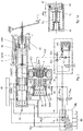
- working chambers 10a, 10b of the piston-cylinder unit with Doppelhubkolben (DHK) run line sections in which check valves V3, V4 are arranged and a common line section, which leads to two other hydraulic line sections in which (normally closed) switching valves EA are arranged to the hydraulic lines HL1, HL2 or via the valve block VBL to the wheel brakes.
- the working chambers 10a, 10b of the double-stroke piston are hydraulically connected via the said line sections and valves EA to the working chambers of the first piston-cylinder unit.
- From the common line section branches off from another line section, which is connected to a working chamber 12 c, which is formed from the back of the piston (DK) of the first piston-cylinder unit.
- a Wegsimulator founded with a travel simulator WS with piston, check valves RV0, RV1 and ÜV, and a diaphragm D and a solenoid valve WA is connected via a hydraulic line HL3 with a working chamber of the piston-cylinder unit with auxiliary piston 16 and corresponds to that in the patent applications DE 10 2013 111 974.3 and DE 10 2014 102 536.9 the applicant, to which reference is made in this regard, described Wegsimulator.
- the overpressure valve ÜV has two functions here: to reduce the throttle power in the normal function at high pedal speed and also in the fallback level RFE, so that the driver can implement the pedal force more quickly in pressure.
- the Wegsimulator worn may suitably be arranged parallel to the THZ or in the valve block VBL.
- the volume or the pressure on the (not shown) pressure control valves in the valve block VBL is directed directly to the brake circuits (BK) and the wheel brakes of the piston-cylinder unit (THZ).
- Pedal way sensors 2a, 2b determine the pressure in the brake circuits BK, which is effected by the drive of the double-stroke piston DHK and corresponding volume supply.
- the path simulator WS determines the pedal force characteristic. With a travel ⁇ WS, this travel simulator is controlled, which accounts for approximately 40% of the total travel of the pedal plunger.
- the volume supply can be changed in a first operating mode 1 in the corresponding path by entering by opening the two valves EA volume directly from the working chamber of Doppelhubkolbens DHK in the piston DK and SK associated hydraulic lines.
- the pistons DK and the SK remain in the position which is given by the path of the DK piston or the spring forces of the springs of the pistons DK and SK.
- the valves EA is practically on both sides of the piston SK and DK the same pressure, so that the push rod piston DK on the pedal ram (PS) 3 is applied, provided that the springs are tuned accordingly.
- This can be defined with an additional spring, such as these, for example FIG. 1a is described.
- the initial position of the floating piston SK with stroke reserve is of great importance for the "worst case" failure of the motor at low ⁇ and subsequent positive ⁇ jump.
- the floating piston SK can only supply sufficient volume if it has sufficient stroke and is not already present at the end of the housing. With the aforementioned vote deliver the piston SK and DK over the residual stroke volume without it comes to a meeting of the pistons DK and SK, in which then disadvantageous asymmetric braking pressures would arise.
- the pressure build-up P on takes place as long as the pedal travel sensors 2a / 2b dictate this to the motor control. Enough for high pressure level or volume, eg. As in fading, the volume of Doppelhubkolbens DHK in the forward stroke on the pressure relief valve S1 is not sufficient, so in the return stroke further volume promotion via the valve S2.
- valve block VBL The eight valves required for pressure control (four inlet valves EV and four outlet valves AV) or alternatively four switching valves SV in multiplex mode MUX are contained in the valve block VBL.
- the double-stroke piston DHK with a forward stroke and return stroke acts permanently, since the volume taken off via the outlet valves AV for the pressure reduction P must be reloaded.
- Fig. 1a shows a spring arrangement with additional spring on the floating piston SK.
- a spring housing 26 is shown with floating piston spring F SK , as is standard in tandem master cylinders THZ.
- F SK floating piston spring
- F X acts a arranged between the floating piston and spring housing spring F X , which corresponds to the initial spring force of the conventional spring of the floating piston SK.
- F X acts a arranged between the floating piston and spring housing spring F X , which corresponds to the initial spring force of the conventional spring of the floating piston SK.
- the spring of the push rod piston DK is tied to a higher level of force.
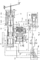
- Fig. 2 shows the next stage of expansion with valves ESV in the line section HL4 and V DK in the line section HL5 and SV5 in the line section HL6 and correspondingly extended functions.
- valve V DK can be designed correspondingly smaller in the switchable pressure range. This allows larger cross-sections or lower magnetic forces, which is cost-relevant.
- valve SV5 Since the pressure rod piston DK is moved via the pedal plunger PS when the valve V DK is closed, the valve SV5 is required in order to avoid negative pressure during the piston movement.
- pressure is reduced P from the valve V DK is opened, and the volume passes through open valve ES and WA in the reservoir VB or via valves EA and AV also in the reservoir VB.
- the configuration of the push rod piston DK is here not according to standard as in the conventional THZ with two seals (the second seal is used in this to avoid leakage oil to the outside).
- the push rod piston DK is connected to the double-stroke piston DHK as a 3-piston solution and advantageously has only one seal to its pressure chamber.
- this version with only one seal D1 can be used here without combination with the double-stroke piston DHK and without stepped piston in non-stepped cylindrical push rod piston DK.
- auxiliary spring does not work because the DK piston is moved by the Pvor pressure, s. also operating mode.
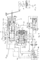
- FIG. 6 a vehicle brake or an actuating system for this purpose is shown, with in series successively arranged first, second and third piston-cylinder units.
- the cross-section of the throttle D is very small, since it is used only for volume compensation with increasing temperature, so that the volume from the brake circuit HL1 can flow into the reservoir VB. Due to the throttle, the volume delivery of the double-stroke piston DHK is much greater than the leakage volume, so that sufficient pressure is created.
- the sump valve SV is used for bleeding the brake circuit HL1.
- the valve EA DK has the task in the case of a leak in the brake circuit HL2 between space 12d and the valve block VBL or in the double-stroke piston DHK to separate the brake circuit HL2 by closing EA. Since this can be ruled out constructively, the valve EA DK can also be saved. Also, the pressure sensor DG can be replaced by measuring the motor current, which is approximately proportional to the pressure.
- the valve EASK is necessary for pressure balance between the brake circuits HL1 and HL2 for the described piston positioning of the piston SK and on the other to leakage in the whole Brake circuit HL1 to separate this.
- the reliable diagnosis is of great importance for the timely detection of leaks.
- This is done essentially by comparing the delivery volume of the Doppelhubkolbens DHK with the pressure level reached, which is determined directly medium pressure transducer DG or indirectly by means of motor current measurement.
- the volume and pressure are compared here with the vehicle-specific pressure-volume curve. This can be done in any operating mode with appropriate plausibility, ie comparison with one or two brake circuits.
- a corresponding circuit of valve or motor usually a separation of a brake circuit.
- the corresponding brake circuits are then no longer supplied from the piston-cylinder unit (Doppelhubkolben).
- the volume of the double-stroke piston is measured, for example, via the motor or the angle of rotation of the rotor, which drives the spindle 5 and thus the double-stroke piston DHK.
Landscapes
- Engineering & Computer Science (AREA)
- Transportation (AREA)
- Mechanical Engineering (AREA)
- Physics & Mathematics (AREA)
- Fluid Mechanics (AREA)
- Regulating Braking Force (AREA)
- Transmission Of Braking Force In Braking Systems (AREA)
- Valves And Accessory Devices For Braking Systems (AREA)
- Braking Systems And Boosters (AREA)
Claims (18)
- Arrangement d'actionnement pour un frein de véhicule, comprenant un dispositif d'actionnement, comme une pédale de frein, au moins une (première) source de pression, notamment un ensemble piston-cylindre (maître-cylindre), lequel peut notamment être actionné au moyen du dispositif d'actionnement, et comprenant une (deuxième) source de pression supplémentaire, notamment un ensemble piston-cylindre (DHK) pourvu d'un mécanisme d'entraînement électromécanique, les sources de pression étant reliées par le biais d'une conduite hydraulique à au moins un circuit de frein afin d'acheminer au circuit de frein un fluide sous pression et de charger le frein de véhicule avec une pression, et comprenant un dispositif à vanne destiné à réguler la pression de freinage, caractérisé en ce que du fluide sous pression peut être acheminé de manière commandée à au moins un circuit de frein dans les deux sens de déplacement du piston, notamment lors d'une excursion aller et retour, au moyen de la (deuxième) source de pression supplémentaire, notamment au moyen d'au moins un piston (DHK) réalisé étagé de l'ensemble piston-cylindre (10, 10a, 10b).
- Arrangement d'actionnement selon la revendication 1, caractérisé en ce qu'aucune vanne, notamment aucune vanne de commutation, n'est disposée dans la portion de conduite (HL1, HL2) de la première source de pression, notamment l'ensemble piston-cylindre (maître-cylindre), au dispositif à vanne (VBL).
- Arrangement d'actionnement selon l'une des revendications précédentes, caractérisé en ce que le (deuxième) ensemble piston-cylindre (DHK) supplémentaire (10) forme deux ou trois chambres de pression (10a, 10b, 10c).
- Arrangement d'actionnement selon l'une des revendications précédentes, caractérisé en ce que la première source de pression, notamment l'ensemble piston-cylindre, est branchée en amont d'une troisième source de pression, notamment un ensemble piston-cylindre (piston auxiliaire), et en ce qu'une chambre de travail d'un troisième dispositif à piston-cylindre (piston auxiliaire) (16) est reliée au moyen d'une conduite hydraulique, dans laquelle est disposé un dispositif à vanne servant notamment à injecter du fluide sous pression dans le ou les circuits de frein, à au moins une chambre de travail du deuxième (DHK) et/ou du premier ensemble piston-cylindre (maître-cylindre).
- Arrangement d'actionnement selon l'une des revendications précédentes, caractérisé en ce qu'entre une chambre de pression (10b) de la (deuxième) source de pression supplémentaire, notamment le piston à double course (10) et une chambre de pression (12c) délimitée par le côté arrière du piston (12a) de la (première) source de pression, notamment l'ensemble piston-cylindre (12, 12a, 12b), se trouve une conduite de liaison hydraulique dans laquelle est disposée au moins une électrovanne (VDK), notamment destinée à commander un piston de l'ensemble piston-cylindre.
- Arrangement d'actionnement selon l'une des revendications précédentes, caractérisé en ce qu'une chambre de pression d'un (troisième) ensemble piston-cylindre supplémentaire (piston auxiliaire) (16) est reliée par le biais d'une conduite hydraulique à un simulateur de course (WS) et notamment à au moins un circuit de frein par le biais d'une électrovanne (ESV) .
- Arrangement d'actionnement selon l'une des revendications 4 à 6, caractérisé en ce que le (troisième) ensemble piston-cylindre supplémentaire (16), lequel est notamment un ensemble piston auxiliaire, possède un simulateur de force-course (KWS) .
- Arrangement d'actionnement selon l'une des revendications précédentes, caractérisé en ce que des électrovannes (EA) sont disposées dans les première et deuxième conduites hydrauliques qui relient les première et deuxième sources de pression ou ensembles piston-cylindre au dispositif à vanne (VBL) et en ce qu'un capteur de pression (DG) est disposé dans une seule de ces conduites ou dans la conduite hydraulique (HL1, HL2) qui mène du deuxième ensemble piston-cylindre au dispositif à vanne (VBL), de préférence à la conduite (HL2).
- Arrangement d'actionnement selon l'une des revendications précédentes, caractérisé en ce que des clapets anti-retour (V3, V4) ou des électrovannes (AS, VF), servant notamment à commander l'arrivée et le départ du fluide sous pression, sont disposés dans les conduites hydrauliques qui relient entre elles les chambres de pression (10a, 10b) du deuxième ensemble piston-cylindre (DHK).
- Arrangement d'actionnement selon l'une des revendications précédentes, caractérisé en ce qu'un circuit de diagnostic destiné au test des garnitures d'étanchéité, notamment des garnitures d'étanchéité du piston à tige-poussoir (DK), du piston flottant (SK) et/ou du piston à double course (DHK) est présent.
- Arrangement d'actionnement selon l'une des revendications précédentes, caractérisé en ce que la deuxième source de pression possède une pompe à entraînement motorisé avec électrovanne (AVMUX) associée et/ou clapet anti-retour (RV) associé.
- Procédé pour faire fonctionner un arrangement de freinage selon l'une des revendications précédentes, caractérisé en ce qu'un fluide sous pression est acheminé au côté arrière d'un piston d'un premier ensemble piston-cylindre au moyen d'une source de pression, notamment un deuxième ensemble piston-cylindre, une pression étant générée dans des circuits de freinage sans utiliser des vannes de séparation, notamment au moyen d'une source de pression, notamment un ensemble piston-cylindre, et en ce que différents modes de fonctionnement, comme la préinjection, l'ABS, la force de pédale maximale ou l'excitation maximale du simulateur de course, le plan de recul sont commandés au moyen d'au moins une électrovanne.
- Système d'actionnement pour un frein de véhicule, comprenant un dispositif d'actionnement, comme une pédale de frein, au moins une première source de pression, notamment un ensemble piston-cylindre (maître-cylindre), lequel peut notamment être actionné au moyen du dispositif d'actionnement, et une deuxième source de pression, notamment un ensemble piston-cylindre (DHK) pourvu d'un mécanisme d'entraînement électromécanique, les sources de pression étant respectivement reliées par le biais d'une conduite hydraulique à au moins un circuit de frein afin d'acheminer au circuit de frein un fluide sous pression et de charger le frein de véhicule avec une pression, et comprenant un dispositif à vanne destiné à réguler la pression de freinage selon l'une des revendications précédentes, caractérisé en ce que la première source de pression, notamment l'ensemble piston-cylindre (maître-cylindre), ne possède qu'un seul piston (SK) générateur de pression.
- Système d'actionnement selon l'une des revendications précédentes, caractérisé en ce qu'au moins une chambre de pression (10a, 10b) de la deuxième source de pression, notamment l'ensemble piston-cylindre (DHK), est reliée hydrauliquement à une chambre de pression ou de travail (12c) formée sur le côté arrière du piston (DK, SK) du premier ensemble piston-cylindre (HZ), notamment par le biais d'un dispositif à vanne.
- Système d'actionnement selon l'une des revendications précédentes, caractérisé en ce que la chambre de travail du piston (SK) est reliée à un réservoir (VB) par le biais d'un reniflard et par le biais d'une électrovanne (VVB) ou d'un arrangement de clapet anti-retour à étranglement (D, SV).
- Système d'actionnement selon l'une des revendications précédentes, caractérisé en ce que le dispositif d'actionnement agit, notamment au moyen d'un poussoir de pédale (3), sur un ressort (F1) ou une combinaison de ressorts du piston (SK).
- Système d'actionnement selon l'une des revendications précédentes, caractérisé en ce qu'une électrovanne (ESV) ouverte au repos est disposée dans une conduite hydraulique du troisième ensemble piston-cylindre (piston auxiliaire) au simulateur de course (WS) et aux circuits de frein (HL1, HL2).
- Système d'actionnement selon l'une des revendications précédentes, caractérisé en ce qu'une électrovanne (WA) fermée au repos est disposée dans une conduite hydraulique du troisième ensemble piston-cylindre (piston auxiliaire) au simulateur de course (WS) et au réservoir (VB).
Applications Claiming Priority (4)
| Application Number | Priority Date | Filing Date | Title |
|---|---|---|---|
| DE102014107112.3A DE102014107112A1 (de) | 2014-05-20 | 2014-05-20 | Betätigungssystem für eine Fahrzeugbremse und Verfahren zum Betrieb des Betätigungssystems |
| DE102014109384 | 2014-07-04 | ||
| DE102014109628.2A DE102014109628A1 (de) | 2014-07-04 | 2014-07-09 | Betätigungssystem für eine Fahrzeugbremse und Verfahren zum Betrieb des Betätigungssystems |
| PCT/EP2015/061105 WO2015177207A1 (fr) | 2014-05-20 | 2015-05-20 | Système d'actionnement d'un frein de véhicule et procédé pour faire fonctionner le système d'actionnement |
Publications (2)
| Publication Number | Publication Date |
|---|---|
| EP3145771A1 EP3145771A1 (fr) | 2017-03-29 |
| EP3145771B1 true EP3145771B1 (fr) | 2018-11-07 |
Family
ID=58056059
Family Applications (1)
| Application Number | Title | Priority Date | Filing Date |
|---|---|---|---|
| EP15723949.2A Active EP3145771B1 (fr) | 2014-05-20 | 2015-05-20 | Systeme d'actuation d'un frein de vehicule et methode d'actuation du frein |
Country Status (4)
| Country | Link |
|---|---|
| US (2) | US20170327098A1 (fr) |
| EP (1) | EP3145771B1 (fr) |
| KR (1) | KR101978278B1 (fr) |
| CN (2) | CN106458167B (fr) |
Cited By (1)
| Publication number | Priority date | Publication date | Assignee | Title |
|---|---|---|---|---|
| WO2023213955A2 (fr) | 2022-05-05 | 2023-11-09 | Thomas Leiber | Système de dynamique de conduite, véhicule et procédé pour faire fonctionner un système de dynamique de conduite |
Families Citing this family (35)
| Publication number | Priority date | Publication date | Assignee | Title |
|---|---|---|---|---|
| DE102014220432A1 (de) * | 2014-10-09 | 2016-04-14 | Continental Teves Ag & Co. Ohg | Hydraulisches Sicherheitssystem, Bremsanlage und Betriebsverfahren |
| DE102014117727A1 (de) * | 2014-12-02 | 2016-06-02 | Ipgate Ag | Betätigungsanlage für zumindest eine hydraulisch betätigbare Einrichtung, insbesondere Fahrzeugbremse |
| US10167015B2 (en) * | 2015-05-11 | 2019-01-01 | GM Global Technology Operations LLC | System for retrofitting vehicle automation |
| DE102015219905A1 (de) * | 2015-10-14 | 2017-04-20 | Continental Teves Ag & Co. Ohg | Verfahren zur Bestimmung einer Leckage eines hydraulischen Bremssystems eines Fahrzeugs |
| DE102015223508A1 (de) * | 2015-11-27 | 2017-06-01 | Robert Bosch Gmbh | Pumpenaggregat für eine hydraulische Fahrzeugbremsanlage |
| JP2018001973A (ja) * | 2016-07-01 | 2018-01-11 | 日立オートモティブシステムズ株式会社 | ブレーキ装置およびブレーキ装置の液漏れ検知方法 |
| DE102017113563A1 (de) | 2017-06-20 | 2018-12-20 | Ipgate Ag | Bremssystem |
| DE102017114556A1 (de) | 2017-06-29 | 2019-01-03 | Ipgate Ag | Vorrichtung für ein hydraulisches Betätigungssystem |
| CN109204271B (zh) * | 2017-06-30 | 2021-01-19 | 比亚迪股份有限公司 | 制动踏板模拟器、汽车制动系统和车辆 |
| CN109204265B (zh) * | 2017-06-30 | 2021-09-21 | 比亚迪股份有限公司 | 制动踏板模拟器、汽车制动系统和车辆 |
| DE102017212360A1 (de) * | 2017-07-19 | 2019-01-24 | Robert Bosch Gmbh | Steuervorrichtung für zumindest eine motorisierte Plungervorrichtung und Verfahren zum Betreiben eines hydraulischen Bremssystems eines Fahrzeugs |
| CN111655556B (zh) * | 2017-12-31 | 2023-08-22 | Zf主动安全美国股份公司 | 车辆制动系统和检测柱塞组件的活塞定位的方法 |
| DE102018206586B4 (de) * | 2018-04-27 | 2020-06-25 | Bayerische Motoren Werke Aktiengesellschaft | Verfahren zum Betreiben eines Fahrzeuges mit einem elektrohydraulischen Bremssystem sowie elektrohydraulisches Bremssystem eines Fahrzeuges |
| WO2019215030A1 (fr) | 2018-05-09 | 2019-11-14 | Ipgate Ag | Système de freinage |
| DE102018208211A1 (de) * | 2018-05-24 | 2019-11-28 | Robert Bosch Gmbh | Verfahren zur Steuerung einer elektronisch schlupfregelbaren Fremdkraftbremsanlage |
| DE102018217618A1 (de) * | 2018-10-15 | 2020-04-16 | Robert Bosch Gmbh | Verfahren und Vorrichtung zur Absicherung eines Kraftfahrzeugs während eines automatisierten Fahrmanövers |
| DE102018221761A1 (de) | 2018-12-14 | 2020-06-18 | Mando Corporation | Bremssystem, enthaltend einen Hauptzylinder mit einem elastischen Pedalgefühlelement |
| DE202019101596U1 (de) * | 2019-02-12 | 2020-05-13 | Ipgate Ag | Hydrauliksystem mit mindestens zwei hydraulischen Kreisen und mindestens zwei Druckversorgungseinrichtungen |
| US12071118B2 (en) | 2019-02-12 | 2024-08-27 | Ipgate Ag | Pressure supply device with double stroke piston for a brake system |
| JP2022520243A (ja) | 2019-02-12 | 2022-03-29 | アイピーゲート・アクチェンゲゼルシャフト | フェールセーフブレーキシステム |
| CN113631443B (zh) | 2019-02-12 | 2024-02-23 | 爱皮加特股份公司 | 具有压力供给装置和用于制动回路的安全门的制动系统 |
| CN113573959B (zh) * | 2019-02-12 | 2024-03-12 | 爱皮加特股份公司 | 失效安全制动系统 |
| DE102019103464A1 (de) | 2019-02-12 | 2020-08-13 | Ipgate Ag | Hydrauliksystem mit mindestens zwei hydraulischen Kreisen und mindestens zwei Druckversorgungseinrichtungen |
| DE202019101586U1 (de) | 2019-02-12 | 2020-05-13 | Ipgate Ag | Packaging für ein Bremssystem |
| DE102019211918A1 (de) * | 2019-08-08 | 2021-02-11 | Robert Bosch Gmbh | Verfahren zur Funktionsprüfung eines Druckerzeugeraggregats einer elektronisch schlupfregelbaren Fremdkraftbremsanlage mit redundanter Bremsdruckerzeugung, insbesondere für ein autonom fahrbares Kraftfahrzeug |
| US11498544B2 (en) * | 2019-11-19 | 2022-11-15 | ZF Active Safety US Inc. | Vehicle brake system and diagnostic method for determining a leak in one or more three-way valves |
| US20210179041A1 (en) * | 2019-12-12 | 2021-06-17 | Continental Automotive Systems Inc. | Method for detecting a leak in a drive-by-wire brake system |
| KR102804693B1 (ko) * | 2019-12-27 | 2025-05-08 | 에이치엘만도 주식회사 | 전자식 브레이크 시스템 및 그 제어방법 |
| CN111907499B (zh) * | 2020-08-07 | 2021-06-08 | 格陆博科技有限公司 | 一种电液制动系统及其制动方法 |
| US11767005B2 (en) * | 2020-08-21 | 2023-09-26 | GM Global Technology Operations LLC | Test sequence for brake system |
| DE102021203227A1 (de) * | 2021-03-30 | 2022-10-06 | Robert Bosch Gesellschaft mit beschränkter Haftung | Fahrzeug und Bremsassistenzeinrichtung für eine hydraulische Bremsanlage für ein Fahrzeug |
| WO2022214521A1 (fr) * | 2021-04-07 | 2022-10-13 | Heinz Leiber | Système de freinage à sécurité intégrée |
| US12208777B2 (en) * | 2021-05-24 | 2025-01-28 | Bwi (Shanghai) Co., Ltd. | Brake-by-wire system with pressure balanced PSU piston |
| CN113830057B (zh) * | 2021-05-24 | 2024-04-30 | 京西重工(上海)有限公司 | 电液制动系统及用于其的压力供应单元 |
| DE102023111467A1 (de) * | 2023-05-03 | 2024-11-07 | Heinz Leiber | 3/2 Wegeventil-Konzept für hydraulische Betätigungssystem |
Family Cites Families (40)
| Publication number | Priority date | Publication date | Assignee | Title |
|---|---|---|---|---|
| DE2531264C2 (de) | 1975-07-12 | 1986-10-02 | Robert Bosch Gmbh, 7000 Stuttgart | Hauptbremszylinder für Zweikreisbremsanlagen |
| JP3496549B2 (ja) * | 1998-04-17 | 2004-02-16 | トヨタ自動車株式会社 | 液圧ブレーキ装置 |
| EP1711385B1 (fr) * | 2004-02-02 | 2009-12-09 | Lucas Automotive GmbH | Generateur de force de freinage pour un systeme de freinage hydraulique de vehicule |
| DE102005017958A1 (de) * | 2004-10-15 | 2006-04-27 | Continental Teves Ag & Co. Ohg | Bremsanlage für Kraftfahrzeuge |
| DE102005055751C5 (de) | 2005-04-21 | 2025-04-24 | Ipgate Ag | Druckmodulatorsteuerung |
| JP2007038698A (ja) * | 2005-07-29 | 2007-02-15 | Toyota Motor Corp | 車両用制動装置 |
| DE102008039305A1 (de) * | 2007-11-21 | 2009-05-28 | Continental Teves Ag & Co. Ohg | Elektrohydraulische Bremsanlage |
| DE102008051316A1 (de) | 2008-08-14 | 2010-02-18 | Ipgate Ag | Bremssystem mit adaptiv steuerbarem Bremsbelaglüftspiel |
| US9016805B2 (en) * | 2009-02-03 | 2015-04-28 | Kelsey-Hayes Company | Hydraulic brake system with controlled boost |
| DE102010040097A1 (de) * | 2009-09-11 | 2011-03-31 | Continental Teves Ag & Co. Ohg | Bremsanlage für Kraftfahrzeuge |
| DE102009045191C5 (de) * | 2009-09-30 | 2020-08-13 | Haldex Brake Products Aktiebolag | Verfahren zum Betrieb einer Bremseinrichtung für ein hydraulisch gebremstes Zugfahrzeug |
| DE102009043484B4 (de) | 2009-09-30 | 2018-05-03 | Ipgate Ag | Bremssystem für ein Hybridfahrzeug und Verfahren zu seinem Betrieb |
| DE102010023865B4 (de) * | 2010-06-15 | 2024-03-28 | Zf Active Safety Gmbh | Hydraulikdruckerzeuger für eine Fahrzeug-Bremsanlage |
| DE102010038555B4 (de) * | 2010-07-28 | 2017-01-26 | Robert Bosch Gmbh | Bremssystem für ein Fahrzeug und Verfahren zum Betreiben eines Bremssystems für ein Fahrzeug |
| US9878697B2 (en) * | 2010-09-17 | 2018-01-30 | Ipgate Ag | Actuating device for a motor vehicle brake system |
| DE102010045617A1 (de) | 2010-09-17 | 2012-03-22 | Ipgate Ag | Betätigungsvorrichtung für eine Kraftfahrzeug-Bremsanlage |
| KR101239705B1 (ko) * | 2010-11-04 | 2013-03-06 | 주식회사 만도 | 유압브레이크 |
| DE102010055044A1 (de) * | 2010-11-08 | 2012-05-10 | Ipgate Ag | Kolben-Zylinder-Vorrichtung, zur Förderung einer Hydraulikflüssigkeit, insbesondere für eine Fahrzeugbremse |
| CN103221285B (zh) * | 2010-11-17 | 2015-09-30 | 本田技研工业株式会社 | 车辆用制动系统 |
| WO2012067197A1 (fr) * | 2010-11-17 | 2012-05-24 | 本田技研工業株式会社 | Système de freinage de véhicule |
| DE102011017436A1 (de) | 2011-04-18 | 2012-10-18 | Ipgate Ag | Betätigungsvorrichtung für eine Fahrzeug-Bremsanlage |
| DE102012203099A1 (de) * | 2011-05-02 | 2012-11-08 | Continental Teves Ag & Co. Ohg | Pedalwegsimulator, Betätigungseinheit für eine hydraulische Bremsanlage sowie Bremsanlage |
| DE102012205962A1 (de) | 2011-05-05 | 2012-11-08 | Continental Teves Ag & Co. Ohg | Bremsanlage für Kraftfahrzeuge sowie Verfahren zum Betrieb einer Bremsanlage |
| DE102011050587A1 (de) | 2011-05-24 | 2012-11-29 | Zf Lenksysteme Gmbh | Elektrische Servolenkung |
| DE102012002791B4 (de) * | 2012-02-15 | 2024-07-25 | Ipgate Ag | Bremsbetätigungsvorrichtung |
| DE102012222897A1 (de) | 2012-02-28 | 2013-08-29 | Continental Teves Ag & Co. Ohg | Verfahren zum Betrieb einer Bremsanlage |
| DE102013203189A1 (de) | 2012-03-06 | 2013-09-12 | Continental Teves Ag & Co. Ohg | Verfahren zur Bestimmung einer Druck-Volumen-Kennlinie einer Radbremse |
| JP5817912B2 (ja) * | 2012-03-07 | 2015-11-18 | トヨタ自動車株式会社 | 液圧ブレーキシステム |
| DE102012103506A1 (de) | 2012-04-20 | 2013-10-24 | Ipgate Ag | Innenläufer-Motor |
| DE102013224870A1 (de) * | 2013-03-05 | 2014-09-11 | Continental Teves Ag & Co. Ohg | Bremsbetätigungseinheit |
| DE102013216423A1 (de) * | 2013-03-05 | 2014-09-11 | Continental Teves Ag & Co. Ohg | Druckbereitstellungseinrichtung und Bremsanlage |
| US9321444B2 (en) * | 2013-03-15 | 2016-04-26 | Kelsey-Hayes Company | Vehicle brake system with dual acting plunger assembly |
| US10940843B2 (en) * | 2013-03-15 | 2021-03-09 | ZF Active Safety US Inc. | Vehicle brake system having plunger power source |
| JP5884245B2 (ja) * | 2013-06-19 | 2016-03-15 | オートリブ日信ブレーキシステムジャパン株式会社 | 車両用ブレーキ液圧制御装置 |
| DE102013111974A1 (de) | 2013-10-30 | 2015-04-30 | Ipgate Ag | Betätigungsvorrichtung für eine Fahrzeugbremse |
| DE102013110188A1 (de) | 2013-09-16 | 2015-03-19 | Ipgate Ag | Betätigungsvorrichtung für eine Kraftfahrzeug-Bremsanlage |
| DE102014102536A1 (de) | 2014-02-26 | 2015-08-27 | Ipgate Ag | Bremsvorrichtung und Verfahren zum Betrieb einer Bremsvorrichtung |
| JP6018039B2 (ja) * | 2013-12-23 | 2016-11-02 | トヨタ自動車株式会社 | 液圧ブレーキシステム |
| DE102014107112A1 (de) | 2014-05-20 | 2015-11-26 | Ipgate Ag | Betätigungssystem für eine Fahrzeugbremse und Verfahren zum Betrieb des Betätigungssystems |
| KR102424997B1 (ko) * | 2017-09-29 | 2022-07-26 | 주식회사 만도 | 전자식 브레이크 시스템 |
-
2015
- 2015-05-20 EP EP15723949.2A patent/EP3145771B1/fr active Active
- 2015-05-20 US US15/312,292 patent/US20170327098A1/en not_active Abandoned
- 2015-05-20 KR KR1020167035692A patent/KR101978278B1/ko active Active
- 2015-05-20 CN CN201580026017.7A patent/CN106458167B/zh active Active
- 2015-05-20 CN CN202110355357.1A patent/CN113147694B/zh active Active
-
2020
- 2020-09-11 US US17/018,094 patent/US10940840B2/en active Active
Non-Patent Citations (1)
| Title |
|---|
| None * |
Cited By (4)
| Publication number | Priority date | Publication date | Assignee | Title |
|---|---|---|---|---|
| WO2023213955A2 (fr) | 2022-05-05 | 2023-11-09 | Thomas Leiber | Système de dynamique de conduite, véhicule et procédé pour faire fonctionner un système de dynamique de conduite |
| EP4631806A2 (fr) | 2022-05-05 | 2025-10-15 | Ipgate Ag | Système de dynamique de conduite, véhicule ainsi que procédé de fonctionnement d'un système de dynamique de conduite |
| EP4631807A2 (fr) | 2022-05-05 | 2025-10-15 | Ipgate Ag | Système de dynamique de conduite, véhicule ainsi que procédé de fonctionnement d'un système de dynamique de conduite |
| EP4631805A2 (fr) | 2022-05-05 | 2025-10-15 | Ipgate Ag | Système de dynamique de conduite, véhicule ainsi que procédé de fonctionnement d'un système de dynamique de conduite |
Also Published As
| Publication number | Publication date |
|---|---|
| US20210001825A1 (en) | 2021-01-07 |
| CN106458167A (zh) | 2017-02-22 |
| US10940840B2 (en) | 2021-03-09 |
| US20170327098A1 (en) | 2017-11-16 |
| KR20170012348A (ko) | 2017-02-02 |
| CN113147694B (zh) | 2024-02-13 |
| KR101978278B1 (ko) | 2019-05-14 |
| CN113147694A (zh) | 2021-07-23 |
| CN106458167B (zh) | 2021-04-27 |
| EP3145771A1 (fr) | 2017-03-29 |
Similar Documents
| Publication | Publication Date | Title |
|---|---|---|
| EP3145771B1 (fr) | Systeme d'actuation d'un frein de vehicule et methode d'actuation du frein | |
| DE112015003240B4 (de) | Betätigungssystem, insbesondere für eine Fahrzeugbremse und Verfahren zum Betrieb des Betätigungssystems | |
| EP3924226B1 (fr) | Système de freinage comportant au moins deux circuits hydrauliques et au moins deux dispositifs compresseurs | |
| DE112014004233B4 (de) | Bremsvorrichtung und Verfahren zum Betrieb einer Bremsvorrichtung | |
| EP3271227B1 (fr) | Système de freinage équipé d'une unité à maître-cylindre de frein à régulation mux innovante (mux 2.0) comprenant au moins une soupape de sortie, et procédé servant à la régulation de pression | |
| EP2707262B1 (fr) | Système de freinage hydraulique de véhicule comprenant un actionneur électromécanique et procédé permettant de faire fonctionner un tel système de freinage hydraulique de véhicule | |
| DE102009055721A1 (de) | Bremssystem mit Speichereinrichtung mit Mehrfachfunktion | |
| DE102015106089A1 (de) | Diagnoseverfahren für ein Bremssystem | |
| DE102014107112A1 (de) | Betätigungssystem für eine Fahrzeugbremse und Verfahren zum Betrieb des Betätigungssystems | |
| WO2013072198A2 (fr) | Système d'actionnement de frein à régulation électronique | |
| DE112018006742T5 (de) | Fahrzeugbremsanlage und verfahren zum erfassen der kolbenstellung einer plungerbaugruppe | |
| DE102014109628A1 (de) | Betätigungssystem für eine Fahrzeugbremse und Verfahren zum Betrieb des Betätigungssystems | |
| EP2822824A1 (fr) | Procede de fonctionnement d'un systeme de freinage de vehicules automobiles, et systeme de freinage | |
| DE102013111974A1 (de) | Betätigungsvorrichtung für eine Fahrzeugbremse | |
| WO2012059175A1 (fr) | Dispositif d'actionnement, en particulier pour un système de freinage de véhicule | |
| DE102018133218A1 (de) | Redundantes Bremssystem mit einer Druckversorgung für E-Fahrzeuge und Fahrzeuge mit autonomem Fahren der Stufe 3 (HAD) bis Stufe 4 (FAD) | |
| DE102011084391A1 (de) | Bremsanlage für Kraftfahrzeuge und Verfahren zu deren Betrieb | |
| DE102011002966A1 (de) | Bremssystem für ein Fahrzeug und Verfahren zum Betreiben eines Bremssystems für ein Fahrzeug | |
| WO2012031718A2 (fr) | Système de freinage présentant une liaison débrayable au moyen d'une pédale de frein pour désaccoupler un dispositif d'entraînement d'une unité piston-cylindre | |
| EP4635808A1 (fr) | Système de freinage avec dispositif d'alimentation en pression et sécurité pour les circuits de freinage | |
| DE102013110188A1 (de) | Betätigungsvorrichtung für eine Kraftfahrzeug-Bremsanlage | |
| DE112012006184T5 (de) | Fahrzeugbremsvorrichtung | |
| DE102014117726A1 (de) | Betätigungsanlage für eine Kraftfahrzeugbremse | |
| DE112016004834T5 (de) | Bremssteuervorrichtung | |
| WO2016184609A1 (fr) | Dispositif de production de force de freinage électrohydraulique pour un système de freinage électrohydraulique de véhicule à moteur |
Legal Events
| Date | Code | Title | Description |
|---|---|---|---|
| STAA | Information on the status of an ep patent application or granted ep patent |
Free format text: STATUS: THE INTERNATIONAL PUBLICATION HAS BEEN MADE |
|
| PUAI | Public reference made under article 153(3) epc to a published international application that has entered the european phase |
Free format text: ORIGINAL CODE: 0009012 |
|
| STAA | Information on the status of an ep patent application or granted ep patent |
Free format text: STATUS: REQUEST FOR EXAMINATION WAS MADE |
|
| 17P | Request for examination filed |
Effective date: 20161216 |
|
| AK | Designated contracting states |
Kind code of ref document: A1 Designated state(s): AL AT BE BG CH CY CZ DE DK EE ES FI FR GB GR HR HU IE IS IT LI LT LU LV MC MK MT NL NO PL PT RO RS SE SI SK SM TR |
|
| AX | Request for extension of the european patent |
Extension state: BA ME |
|
| DAV | Request for validation of the european patent (deleted) | ||
| DAX | Request for extension of the european patent (deleted) | ||
| GRAP | Despatch of communication of intention to grant a patent |
Free format text: ORIGINAL CODE: EPIDOSNIGR1 |
|
| STAA | Information on the status of an ep patent application or granted ep patent |
Free format text: STATUS: GRANT OF PATENT IS INTENDED |
|
| INTG | Intention to grant announced |
Effective date: 20180605 |
|
| GRAS | Grant fee paid |
Free format text: ORIGINAL CODE: EPIDOSNIGR3 |
|
| GRAA | (expected) grant |
Free format text: ORIGINAL CODE: 0009210 |
|
| STAA | Information on the status of an ep patent application or granted ep patent |
Free format text: STATUS: THE PATENT HAS BEEN GRANTED |
|
| AK | Designated contracting states |
Kind code of ref document: B1 Designated state(s): AL AT BE BG CH CY CZ DE DK EE ES FI FR GB GR HR HU IE IS IT LI LT LU LV MC MK MT NL NO PL PT RO RS SE SI SK SM TR |
|
| REG | Reference to a national code |
Ref country code: GB Ref legal event code: FG4D Free format text: NOT ENGLISH |
|
| REG | Reference to a national code |
Ref country code: CH Ref legal event code: EP Ref country code: AT Ref legal event code: REF Ref document number: 1061703 Country of ref document: AT Kind code of ref document: T Effective date: 20181115 |
|
| REG | Reference to a national code |
Ref country code: DE Ref legal event code: R096 Ref document number: 502015006778 Country of ref document: DE |
|
| REG | Reference to a national code |
Ref country code: IE Ref legal event code: FG4D Free format text: LANGUAGE OF EP DOCUMENT: GERMAN |
|
| REG | Reference to a national code |
Ref country code: DE Ref legal event code: R082 Ref document number: 502015006778 Country of ref document: DE Representative=s name: MEISSNER BOLTE PATENTANWAELTE RECHTSANWAELTE P, DE |
|
| REG | Reference to a national code |
Ref country code: NL Ref legal event code: MP Effective date: 20181107 |
|
| REG | Reference to a national code |
Ref country code: LT Ref legal event code: MG4D |
|
| PG25 | Lapsed in a contracting state [announced via postgrant information from national office to epo] |
Ref country code: ES Free format text: LAPSE BECAUSE OF FAILURE TO SUBMIT A TRANSLATION OF THE DESCRIPTION OR TO PAY THE FEE WITHIN THE PRESCRIBED TIME-LIMIT Effective date: 20181107 Ref country code: LT Free format text: LAPSE BECAUSE OF FAILURE TO SUBMIT A TRANSLATION OF THE DESCRIPTION OR TO PAY THE FEE WITHIN THE PRESCRIBED TIME-LIMIT Effective date: 20181107 Ref country code: IS Free format text: LAPSE BECAUSE OF FAILURE TO SUBMIT A TRANSLATION OF THE DESCRIPTION OR TO PAY THE FEE WITHIN THE PRESCRIBED TIME-LIMIT Effective date: 20190307 Ref country code: NO Free format text: LAPSE BECAUSE OF FAILURE TO SUBMIT A TRANSLATION OF THE DESCRIPTION OR TO PAY THE FEE WITHIN THE PRESCRIBED TIME-LIMIT Effective date: 20190207 Ref country code: FI Free format text: LAPSE BECAUSE OF FAILURE TO SUBMIT A TRANSLATION OF THE DESCRIPTION OR TO PAY THE FEE WITHIN THE PRESCRIBED TIME-LIMIT Effective date: 20181107 Ref country code: BG Free format text: LAPSE BECAUSE OF FAILURE TO SUBMIT A TRANSLATION OF THE DESCRIPTION OR TO PAY THE FEE WITHIN THE PRESCRIBED TIME-LIMIT Effective date: 20190207 Ref country code: HR Free format text: LAPSE BECAUSE OF FAILURE TO SUBMIT A TRANSLATION OF THE DESCRIPTION OR TO PAY THE FEE WITHIN THE PRESCRIBED TIME-LIMIT Effective date: 20181107 Ref country code: LV Free format text: LAPSE BECAUSE OF FAILURE TO SUBMIT A TRANSLATION OF THE DESCRIPTION OR TO PAY THE FEE WITHIN THE PRESCRIBED TIME-LIMIT Effective date: 20181107 |
|
| PG25 | Lapsed in a contracting state [announced via postgrant information from national office to epo] |
Ref country code: GR Free format text: LAPSE BECAUSE OF FAILURE TO SUBMIT A TRANSLATION OF THE DESCRIPTION OR TO PAY THE FEE WITHIN THE PRESCRIBED TIME-LIMIT Effective date: 20190208 Ref country code: RS Free format text: LAPSE BECAUSE OF FAILURE TO SUBMIT A TRANSLATION OF THE DESCRIPTION OR TO PAY THE FEE WITHIN THE PRESCRIBED TIME-LIMIT Effective date: 20181107 Ref country code: AL Free format text: LAPSE BECAUSE OF FAILURE TO SUBMIT A TRANSLATION OF THE DESCRIPTION OR TO PAY THE FEE WITHIN THE PRESCRIBED TIME-LIMIT Effective date: 20181107 Ref country code: SE Free format text: LAPSE BECAUSE OF FAILURE TO SUBMIT A TRANSLATION OF THE DESCRIPTION OR TO PAY THE FEE WITHIN THE PRESCRIBED TIME-LIMIT Effective date: 20181107 Ref country code: NL Free format text: LAPSE BECAUSE OF FAILURE TO SUBMIT A TRANSLATION OF THE DESCRIPTION OR TO PAY THE FEE WITHIN THE PRESCRIBED TIME-LIMIT Effective date: 20181107 Ref country code: PT Free format text: LAPSE BECAUSE OF FAILURE TO SUBMIT A TRANSLATION OF THE DESCRIPTION OR TO PAY THE FEE WITHIN THE PRESCRIBED TIME-LIMIT Effective date: 20190307 |
|
| PG25 | Lapsed in a contracting state [announced via postgrant information from national office to epo] |
Ref country code: DK Free format text: LAPSE BECAUSE OF FAILURE TO SUBMIT A TRANSLATION OF THE DESCRIPTION OR TO PAY THE FEE WITHIN THE PRESCRIBED TIME-LIMIT Effective date: 20181107 Ref country code: PL Free format text: LAPSE BECAUSE OF FAILURE TO SUBMIT A TRANSLATION OF THE DESCRIPTION OR TO PAY THE FEE WITHIN THE PRESCRIBED TIME-LIMIT Effective date: 20181107 Ref country code: IT Free format text: LAPSE BECAUSE OF FAILURE TO SUBMIT A TRANSLATION OF THE DESCRIPTION OR TO PAY THE FEE WITHIN THE PRESCRIBED TIME-LIMIT Effective date: 20181107 Ref country code: CZ Free format text: LAPSE BECAUSE OF FAILURE TO SUBMIT A TRANSLATION OF THE DESCRIPTION OR TO PAY THE FEE WITHIN THE PRESCRIBED TIME-LIMIT Effective date: 20181107 |
|
| REG | Reference to a national code |
Ref country code: DE Ref legal event code: R097 Ref document number: 502015006778 Country of ref document: DE |
|
| PG25 | Lapsed in a contracting state [announced via postgrant information from national office to epo] |
Ref country code: RO Free format text: LAPSE BECAUSE OF FAILURE TO SUBMIT A TRANSLATION OF THE DESCRIPTION OR TO PAY THE FEE WITHIN THE PRESCRIBED TIME-LIMIT Effective date: 20181107 Ref country code: EE Free format text: LAPSE BECAUSE OF FAILURE TO SUBMIT A TRANSLATION OF THE DESCRIPTION OR TO PAY THE FEE WITHIN THE PRESCRIBED TIME-LIMIT Effective date: 20181107 Ref country code: SM Free format text: LAPSE BECAUSE OF FAILURE TO SUBMIT A TRANSLATION OF THE DESCRIPTION OR TO PAY THE FEE WITHIN THE PRESCRIBED TIME-LIMIT Effective date: 20181107 Ref country code: SK Free format text: LAPSE BECAUSE OF FAILURE TO SUBMIT A TRANSLATION OF THE DESCRIPTION OR TO PAY THE FEE WITHIN THE PRESCRIBED TIME-LIMIT Effective date: 20181107 |
|
| PLBE | No opposition filed within time limit |
Free format text: ORIGINAL CODE: 0009261 |
|
| STAA | Information on the status of an ep patent application or granted ep patent |
Free format text: STATUS: NO OPPOSITION FILED WITHIN TIME LIMIT |
|
| 26N | No opposition filed |
Effective date: 20190808 |
|
| PG25 | Lapsed in a contracting state [announced via postgrant information from national office to epo] |
Ref country code: SI Free format text: LAPSE BECAUSE OF FAILURE TO SUBMIT A TRANSLATION OF THE DESCRIPTION OR TO PAY THE FEE WITHIN THE PRESCRIBED TIME-LIMIT Effective date: 20181107 |
|
| REG | Reference to a national code |
Ref country code: CH Ref legal event code: PL |
|
| GBPC | Gb: european patent ceased through non-payment of renewal fee |
Effective date: 20190520 |
|
| PG25 | Lapsed in a contracting state [announced via postgrant information from national office to epo] |
Ref country code: LI Free format text: LAPSE BECAUSE OF NON-PAYMENT OF DUE FEES Effective date: 20190531 Ref country code: CH Free format text: LAPSE BECAUSE OF NON-PAYMENT OF DUE FEES Effective date: 20190531 Ref country code: MC Free format text: LAPSE BECAUSE OF FAILURE TO SUBMIT A TRANSLATION OF THE DESCRIPTION OR TO PAY THE FEE WITHIN THE PRESCRIBED TIME-LIMIT Effective date: 20181107 |
|
| REG | Reference to a national code |
Ref country code: BE Ref legal event code: MM Effective date: 20190531 |
|
| PG25 | Lapsed in a contracting state [announced via postgrant information from national office to epo] |
Ref country code: LU Free format text: LAPSE BECAUSE OF NON-PAYMENT OF DUE FEES Effective date: 20190520 |
|
| PG25 | Lapsed in a contracting state [announced via postgrant information from national office to epo] |
Ref country code: TR Free format text: LAPSE BECAUSE OF FAILURE TO SUBMIT A TRANSLATION OF THE DESCRIPTION OR TO PAY THE FEE WITHIN THE PRESCRIBED TIME-LIMIT Effective date: 20181107 |
|
| PG25 | Lapsed in a contracting state [announced via postgrant information from national office to epo] |
Ref country code: GB Free format text: LAPSE BECAUSE OF NON-PAYMENT OF DUE FEES Effective date: 20190520 Ref country code: IE Free format text: LAPSE BECAUSE OF NON-PAYMENT OF DUE FEES Effective date: 20190520 |
|
| PG25 | Lapsed in a contracting state [announced via postgrant information from national office to epo] |
Ref country code: BE Free format text: LAPSE BECAUSE OF NON-PAYMENT OF DUE FEES Effective date: 20190531 |
|
| PG25 | Lapsed in a contracting state [announced via postgrant information from national office to epo] |
Ref country code: CY Free format text: LAPSE BECAUSE OF FAILURE TO SUBMIT A TRANSLATION OF THE DESCRIPTION OR TO PAY THE FEE WITHIN THE PRESCRIBED TIME-LIMIT Effective date: 20181107 |
|
| REG | Reference to a national code |
Ref country code: AT Ref legal event code: MM01 Ref document number: 1061703 Country of ref document: AT Kind code of ref document: T Effective date: 20200520 |
|
| PG25 | Lapsed in a contracting state [announced via postgrant information from national office to epo] |
Ref country code: HU Free format text: LAPSE BECAUSE OF FAILURE TO SUBMIT A TRANSLATION OF THE DESCRIPTION OR TO PAY THE FEE WITHIN THE PRESCRIBED TIME-LIMIT; INVALID AB INITIO Effective date: 20150520 Ref country code: MT Free format text: LAPSE BECAUSE OF FAILURE TO SUBMIT A TRANSLATION OF THE DESCRIPTION OR TO PAY THE FEE WITHIN THE PRESCRIBED TIME-LIMIT Effective date: 20181107 |
|
| PG25 | Lapsed in a contracting state [announced via postgrant information from national office to epo] |
Ref country code: AT Free format text: LAPSE BECAUSE OF NON-PAYMENT OF DUE FEES Effective date: 20200520 |
|
| PG25 | Lapsed in a contracting state [announced via postgrant information from national office to epo] |
Ref country code: MK Free format text: LAPSE BECAUSE OF FAILURE TO SUBMIT A TRANSLATION OF THE DESCRIPTION OR TO PAY THE FEE WITHIN THE PRESCRIBED TIME-LIMIT Effective date: 20181107 |
|
| PGFP | Annual fee paid to national office [announced via postgrant information from national office to epo] |
Ref country code: DE Payment date: 20250521 Year of fee payment: 11 |
|
| PGFP | Annual fee paid to national office [announced via postgrant information from national office to epo] |
Ref country code: FR Payment date: 20250528 Year of fee payment: 11 |