EP3146105B1 - Elastische binde - Google Patents
Elastische binde Download PDFInfo
- Publication number
- EP3146105B1 EP3146105B1 EP15723523.5A EP15723523A EP3146105B1 EP 3146105 B1 EP3146105 B1 EP 3146105B1 EP 15723523 A EP15723523 A EP 15723523A EP 3146105 B1 EP3146105 B1 EP 3146105B1
- Authority
- EP
- European Patent Office
- Prior art keywords
- bandage
- elastic
- stretch
- stop
- threads
- Prior art date
- Legal status (The legal status is an assumption and is not a legal conclusion. Google has not performed a legal analysis and makes no representation as to the accuracy of the status listed.)
- Active
Links
Images
Classifications
-
- D—TEXTILES; PAPER
- D06—TREATMENT OF TEXTILES OR THE LIKE; LAUNDERING; FLEXIBLE MATERIALS NOT OTHERWISE PROVIDED FOR
- D06H—MARKING, INSPECTING, SEAMING OR SEVERING TEXTILE MATERIALS
- D06H1/00—Marking textile materials; Marking in combination with metering or inspecting
- D06H1/04—Marking textile materials; Marking in combination with metering or inspecting by attaching threads, tags, or the like
- D06H1/043—Marking textile materials; Marking in combination with metering or inspecting by attaching threads, tags, or the like by attaching threads
-
- A—HUMAN NECESSITIES
- A61—MEDICAL OR VETERINARY SCIENCE; HYGIENE
- A61F—FILTERS IMPLANTABLE INTO BLOOD VESSELS; PROSTHESES; DEVICES PROVIDING PATENCY TO, OR PREVENTING COLLAPSING OF, TUBULAR STRUCTURES OF THE BODY, e.g. STENTS; ORTHOPAEDIC, NURSING OR CONTRACEPTIVE DEVICES; FOMENTATION; TREATMENT OR PROTECTION OF EYES OR EARS; BANDAGES, DRESSINGS OR ABSORBENT PADS; FIRST-AID KITS
- A61F13/00—Bandages or dressings; Absorbent pads
- A61F13/01—Non-adhesive bandages or dressings
- A61F13/01021—Non-adhesive bandages or dressings characterised by the structure of the dressing
- A61F13/01029—Non-adhesive bandages or dressings characterised by the structure of the dressing made of multiple layers
-
- A—HUMAN NECESSITIES
- A61—MEDICAL OR VETERINARY SCIENCE; HYGIENE
- A61F—FILTERS IMPLANTABLE INTO BLOOD VESSELS; PROSTHESES; DEVICES PROVIDING PATENCY TO, OR PREVENTING COLLAPSING OF, TUBULAR STRUCTURES OF THE BODY, e.g. STENTS; ORTHOPAEDIC, NURSING OR CONTRACEPTIVE DEVICES; FOMENTATION; TREATMENT OR PROTECTION OF EYES OR EARS; BANDAGES, DRESSINGS OR ABSORBENT PADS; FIRST-AID KITS
- A61F13/00—Bandages or dressings; Absorbent pads
- A61F13/01—Non-adhesive bandages or dressings
- A61F13/01034—Non-adhesive bandages or dressings characterised by a property
- A61F13/01038—Flexibility, stretchability or elasticity
-
- D—TEXTILES; PAPER
- D03—WEAVING
- D03D—WOVEN FABRICS; METHODS OF WEAVING; LOOMS
- D03D15/00—Woven fabrics characterised by the material, structure or properties of the fibres, filaments, yarns, threads or other warp or weft elements used
- D03D15/50—Woven fabrics characterised by the material, structure or properties of the fibres, filaments, yarns, threads or other warp or weft elements used characterised by the properties of the yarns or threads
- D03D15/56—Woven fabrics characterised by the material, structure or properties of the fibres, filaments, yarns, threads or other warp or weft elements used characterised by the properties of the yarns or threads elastic
-
- A—HUMAN NECESSITIES
- A61—MEDICAL OR VETERINARY SCIENCE; HYGIENE
- A61F—FILTERS IMPLANTABLE INTO BLOOD VESSELS; PROSTHESES; DEVICES PROVIDING PATENCY TO, OR PREVENTING COLLAPSING OF, TUBULAR STRUCTURES OF THE BODY, e.g. STENTS; ORTHOPAEDIC, NURSING OR CONTRACEPTIVE DEVICES; FOMENTATION; TREATMENT OR PROTECTION OF EYES OR EARS; BANDAGES, DRESSINGS OR ABSORBENT PADS; FIRST-AID KITS
- A61F13/00—Bandages or dressings; Absorbent pads
- A61F2013/00089—Wound bandages
- A61F2013/00119—Wound bandages elastic
- A61F2013/00123—Wound bandages elastic with elastic indicator
-
- D—TEXTILES; PAPER
- D10—INDEXING SCHEME ASSOCIATED WITH SUBLASSES OF SECTION D, RELATING TO TEXTILES
- D10B—INDEXING SCHEME ASSOCIATED WITH SUBLASSES OF SECTION D, RELATING TO TEXTILES
- D10B2201/00—Cellulose-based fibres, e.g. vegetable fibres
- D10B2201/01—Natural vegetable fibres
- D10B2201/02—Cotton
-
- D—TEXTILES; PAPER
- D10—INDEXING SCHEME ASSOCIATED WITH SUBLASSES OF SECTION D, RELATING TO TEXTILES
- D10B—INDEXING SCHEME ASSOCIATED WITH SUBLASSES OF SECTION D, RELATING TO TEXTILES
- D10B2201/00—Cellulose-based fibres, e.g. vegetable fibres
- D10B2201/20—Cellulose-derived artificial fibres
- D10B2201/22—Cellulose-derived artificial fibres made from cellulose solutions
- D10B2201/24—Viscose
-
- D—TEXTILES; PAPER
- D10—INDEXING SCHEME ASSOCIATED WITH SUBLASSES OF SECTION D, RELATING TO TEXTILES
- D10B—INDEXING SCHEME ASSOCIATED WITH SUBLASSES OF SECTION D, RELATING TO TEXTILES
- D10B2331/00—Fibres made from polymers obtained otherwise than by reactions only involving carbon-to-carbon unsaturated bonds, e.g. polycondensation products
- D10B2331/04—Fibres made from polymers obtained otherwise than by reactions only involving carbon-to-carbon unsaturated bonds, e.g. polycondensation products polyesters, e.g. polyethylene terephthalate [PET]
-
- D—TEXTILES; PAPER
- D10—INDEXING SCHEME ASSOCIATED WITH SUBLASSES OF SECTION D, RELATING TO TEXTILES
- D10B—INDEXING SCHEME ASSOCIATED WITH SUBLASSES OF SECTION D, RELATING TO TEXTILES
- D10B2509/00—Medical; Hygiene
- D10B2509/02—Bandages, dressings or absorbent pads
- D10B2509/028—Elastic support stockings or elastic bandages
Definitions
- the invention relates to an elastic bandage comprising a woven fabric with weft threads and elastic warp threads, whereby the bandage is given elasticity in the longitudinal direction.
- Such a binding is in particular woven in a plain weave; however, any other types of weave are also conceivable, with additional threads, such as leno threads, etc. also being provided.
- Such bandages find z. B. use as so-called compression bandages.
- bandages or bandages are used as short-stretch bandages which ensure a high working pressure with a low resting pressure and at the same time are comfortable for the patient to wear.
- bandage and “bandage” are to be used synonymously.
- the prior art for example from the DE 10 2005 033 720 A1 previously known, with a bandage which is longitudinally elastic in the warp direction and which can also be used as a compression bandage, that the low resting pressure remains almost over the entire extensibility of the bandage.
- the bandage can be stretched almost over its entire extensibility with the least amount of force. The resting pressure rises only with a relatively high application stretch.
- the sanitary napkin known in the prior art has a curve that is as flat as possible in the force stretching range in the range of at least 2/3 of the total stretching. Only after reaching the second third of the curve (extensibility) is a significant increase in force desired. This is intended to provide a high level of therapy safety, since an almost constant working pressure can be set over a wide range of application stretching.
- an elastic hose band is known in which an insert is received in the interior of the hose, which limits the maximum extensibility of the band or the band section.
- Such straps can be used as elastic bands for securing loads in motor vehicles, etc.
- a sanitary napkin according to the preamble of claim 1 is off WO 96/31175 A1 known.
- the object of the invention is to provide a bandage or bandage which signals to the user when an elastic bandage is stretched sufficiently to apply the compression pressure required for therapy to a patient's limb.
- the invention achieves this object by an elastic bandage according to the preamble, in which at least one stop path is applied to the woven fabric, through which a predetermined stretch limit or expansion threshold of the bandage can be displayed.
- the stop path which limits or at least impedes further stretching of the elastic bandage at a given stretch limit or stretch threshold, gives the user a signal as to when he has achieved the correct, ie sufficient stretch, of the elastic bandage to provide sufficient compressive force on one limb and, on the other hand, to minimize misapplication errors due to excessive stretching of the napkin or even avoided.
- This additional stretch limit or stretch threshold provides a simple possibility for the user below the existing stretch limit of each elastic bandage, which is given by the stretching until the bandage is torn, even if the bandage is poorly operated due to poor therapeutic knowledge as well as by stretching the bandage too much.
- the at least one stop thread is applied to the woven fabric and not, as is already known in the prior art, integrated into it in the weaving process.
- bandages can initially be produced independently of the expansion threshold or expansion limit to be set later, all of which are of identical design. Only after the textile fabrics have been woven, which are then made up into bindings, can the stopping threads be applied to the binding in accordance with the desired expansion threshold or limit. This greatly simplifies the setting of the expansion threshold or expansion limit, since the corresponding bandages or bandages can be pre-assembled and stretched to the desired expansion threshold or expansion limit, in order to then be provided with one or more corresponding stop threads, which then the specified expansion threshold or expansion limit for further Signaling uses. This does not change the weaving process as such.
- such woven fabrics have, on the one hand, a freely adjustable extensibility over a wide range and, in particular, a compression force when the patient is at rest with the bandage on of less than 800 cN / cm, in particular less than 350 cN / cm, in particular less than 300 cN / cm and in particular between 300 and 150 cN / cm bandage width when applied.
- the pressure at rest is the constant pressure that the bandage at rest, ie when the muscles are relaxed, exerts on the tissue and the vessels, ie on the body part to be treated.
- the force that is used to stretch the bandage corresponds to the force that acts as resting pressure on the tissue, ie on the part of the body to be treated.
- the working pressure is the pressure that the contracting, working muscle opposes the resistance of the compression bandage by increasing its circumference.
- the bandages according to the invention can be both short-stretch and long-stretch bandages, the provision of an expansion threshold or an expansion stop particularly for long-stretch bandages appearing to be particularly advantageous.
- warp threads are designed as cotton-elastic threads.
- the use of cotton elastic threads improves the wearing properties of the bandage.
- the compression properties in particular the low resting pressure in the medical sense and the high working pressure compared to conventional compression bandages based on elastic polymers, such as rubber, polyurethane elastomers, textured polyamide or polyester yarns, which generate a high resting pressure with a low working pressure, can be significantly improved will.
- the tensile strength properties are improved in the direction of an increased, low resting pressure, which remains approximately over the entire elasticity of the bandage. I. E. the bandage can be stretched almost over its entire extensibility with the least amount of force.
- the stretchability of cotton-elastic short-stretch bandages can be 30% to 110%, preferably 40% to 100% and particularly preferably 50% to 90% (measured in accordance with DIN 61632).
- the extensibility can be 30% to 250%, in particular 30% to 200% and particularly preferably 30% to 150% (measured in accordance with DIN 61632).
- a bandage according to the invention has a compression force of less than 800 cN when the patient is at rest with the bandage on when the bandage is stretched less than 50%, in particular less than 60%, and very particularly preferably less than 65% (based on the total elongation of the bandage according to DIN 61632) / cm bandage width, in particular less than 350 cN / cm and in particular between 300 cN / cm to 150 cN / cm bandage width.
- a napkin according to the invention thus has a restoring force greater than 800 cN / cm napkin width, in particular greater than 350 cN / cm napkin width and in particular greater than 300 cN / cm napkin width only in the range of 80% to 100% of the total elongation in the longitudinal direction.
- weft threads are designed to be essentially inelastic.
- a sanitary napkin according to the invention which, for. B. used cotton-elastic warp threads or warp threads made of elastic polymers and has essentially inelastic weft threads, a non-elastic bandage is produced.
- elastic weft threads can also be used, for example also cotton-elastic weft threads, so that then, in addition to longitudinal elasticity of the bandage, there is also elasticity in the transverse direction and a bi-elastic bandage is produced.
- the leno threads can be designed as elastic or inelastic threads.
- the stopping threads or the at least one stopping path provided for displaying the expansion threshold or expansion limit can take place in that this is connected to the textile fabric by sewing, over-sewing, embroidering, welding or gluing. Additional fixing threads can be provided for this purpose.
- Sewing refers to a process in which a thread is placed on a finished flat structure and then fixed with another thread using a sewing technique. When sewing over, the stop thread itself is the thread that is sewn onto a finished fabric.
- Embroidery describes the embroidery technique with all its variants.
- the stop path can rest on a textile fabric or protrude from its plane (floating). Depending on the length and selection of the stop path, e.g. as an elastic or inelastic stop path, this rests on the structure in "serpentine lines".
- the woven sheet-like structure can have, for example, thermoplastic fibers that allow welding by thermal or ultrasonic welding of the stop threads to the fabric. This must also be taken into account when selecting the material for the darning threads. Alternatively, gluing is also conceivable.
- the stopper threads are either inelastic threads, whereby natural plant fibers, fibers of animal origin or synthetic fibers can be used here.
- these threads can consist of cotton, rayon, flax, wool, viscose, silk and / or synthetic fibers, cotton and viscose being preferred.
- Fibers made of polyamide, polyester, polypropylene or polyacrylic can preferably be used as synthetic fibers; especially polyamides and polyesters.
- the bandages, especially in the case of long-stretch bandages, can preferably consist of polyurethane or elastane or comprise this.
- elastic stop threads can also be used, which have a have less elasticity than the woven fabric (base fabric) of the bandage.
- Elastic stop threads offer the advantage of being able to implement an expansion threshold particularly easily, instead of a defined expansion stop.
- the darning threads can be single yarns, but also twisted and wrapped yarns.
- One or more stop threads can be connected to the fabric, whereby the elongation limit or the elongation threshold can be precisely adapted to an elongation value required for the respective application through the placement and the number of stop threads.
- the stop threads can be attached in such a way that the elastic bandage is stretched to a required elongation value and the stop threads are then connected to the woven fabric under tension at this desired elongation value, which is to be displayed as the elongation limit or elongation threshold, so that then After the bandage has been relaxed, the at least one stop path is laid in waves, so that the bandage can still be stretched elastically up to the stretch limit or stretch threshold, but when the stretch threshold or stretch limit is reached, the at least one stop path indicates that the desired stretch value has been reached.
- the at least one stop path is then meandering, i. H. with a thread reserve, on the woven fabric and is fixed, for example, by a fixing thread or adhesive points on the fabric.
- a thread reserve i. H.
- the stop thread tightens to the point at which it is almost a straight line in the longitudinal direction of the sheet.
- the signaling effect of the stop path begins with regard to the expansion stop or the expansion threshold.
- an elastic stop path it is not absolutely necessary to lay the stop path in waves or only to a lesser extent. It is also possible to use an elastic To apply stop threads to an unstretched bandage or only to a bandage that has not been stretched to the desired expansion threshold or limit.
- the bandage can preferably have an extensibility of 20% to 100% and in particular from 30% to 90%, in particular from 30% to 70%, in which the at least one stop thread signals that the expansion threshold and / or limit has been reached.
- the force associated with the corresponding elongation can in particular be set in the range from 10 cN / cm to 50 cN / cm, in particular from 20 cN / cm to 40 cN / cm.
- the at least one stop thread can have a thickness that is greater, equal to or finer than that of the weft or warp threads.
- the at least one stop path can be connected to the fabric of the napkin at at least two points, but preferably at least 1 to 50 points per 10 cm napkin length and at least 3 and 20 points per 10 cm napkin length and preferably at least 5 to 15 points per 10 cm napkin length be.
- stop path can also be made for the stop path to stand out clearly visually from the flat structure and, if necessary, to be contrasted in terms of color here.
- An expansion stop is to be understood as the actual limitation of the further expansion of the elastic bandage, with the at least one stop path being torn if the signaled expansion stop is exceeded.
- a bandage with a stretch stop eliminates the possibility of overstretching the bandage. If an expansion threshold is provided, when the expansion threshold is reached, the force required for further expansion suddenly increases significantly, so that a signaling effect is achieved as a result. The risk of incorrect application is not completely ruled out with a bandage with an expansion threshold, but it is significantly minimized.
- Such an elastic bandage can in particular be a compression bandage, as is preferably used in the area of Treatment of venous and lymphatic ailments is used.
- Such bandages are z.
- the invention can also be implemented with long-stretch bandages, such as are preferably used for the treatment of venous and lymphatic disorders.
- Such a bandage is intended to undergo an elastically reversible change in shape when it is put on and preferably has a recovery of greater than 50%, so that it can be used multiple times without losing the compression effect.
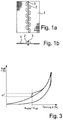
- Figure 1 shows in a representation a) a detail from the napkin according to the invention with a woven flat structure 1 comprising elastic warp and preferably inelastic weft threads.
- a stop thread 2 is attached to the flat structure by means of a fixing thread 3.
- the stopping thread can preferably be high-twisted cotton threads or elastane threads wrapped with wrapping thread, wherein the wrapping thread can consist of polyamide or cotton.
- the fixing threads can be commercially available embroidery or sewing threads, such as those used in the clothing industry. These can include, for example, polyamides.
- the stop path is applied when the elastic bandage is stretched, the elastic bandage being stretched so far when the fixing thread is applied that a desired compression force is achieved and this expansion is then to be displayed as an expansion threshold or limit for further uses.
- the stopping path is then connected to the fabric at several points, which are in particular distributed equidistantly over the length of the bandage, the stopping path running approximately in a straight line in the longitudinal direction of the fabric 1 during the connection. After the fabric 1 has relaxed, the stopping path 2 then lays itself in waves or is meandered so that a thread reserve rests on the fabric 1. If the flat structure 1 is then tightened again when the elastic bandage is put on, the stop path likewise tightens up to the specified expansion threshold or the specified expansion stop (expansion limit).
- the stop thread can also be applied to the unstretched bandage. This can be provided, for example, if the stop path itself has elasticity and in particular the expansion threshold or limit is determined by the expansion limit of the stop path. This has an elasticity that is less than the elasticity of the bandage.
- the second representation b) in Figure 1 shows a corresponding elastic bandage in a cross section.
- the stop thread 2 is here designed with a considerably larger thread thickness and also stands out from the flat structure 1 in terms of color design, so that here, too, it is easy for an investor of a corresponding bandage to visually recognize whether an expansion limit or threshold has been reached.
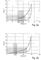
- Figure 2 shows in the representations a) and b) force-expansion diagrams for short-stretch and long-stretch bandages.
- illustration a) shows, in the case of a short-stretch bandage, as described in example a above, the force-elongation behavior for the elongation as well as the recovery.
- the desired stretch range and the usual force range when applying are shown marked.
- the force range runs horizontally, the stretch range vertically.
- an analogous force-expansion diagram for a long-stretch bandage is also given with a load of 10 N / cm, with the desired stretching range and the usual force range during application being marked here as well.
- the long-stretch bandage therefore corresponds to that shown in example b above.
- Figure 3 shows a force-expansion diagram, the solid line showing a bandage with conventional force-elongation behavior and the dash-dotted line showing a bandage with an expansion threshold ⁇ schw , where ⁇ schw corresponds to the optimal desired expansion ⁇ opt.
Landscapes
- Engineering & Computer Science (AREA)
- Health & Medical Sciences (AREA)
- Animal Behavior & Ethology (AREA)
- Biomedical Technology (AREA)
- Heart & Thoracic Surgery (AREA)
- Vascular Medicine (AREA)
- Life Sciences & Earth Sciences (AREA)
- Textile Engineering (AREA)
- General Health & Medical Sciences (AREA)
- Public Health (AREA)
- Veterinary Medicine (AREA)
- Materials Engineering (AREA)
- Chemical & Material Sciences (AREA)
- Materials For Medical Uses (AREA)
Description
- Die Erfindung betrifft eine elastische Binde umfassend ein gewebtes Flächengebilde mit Schussfäden sowie elastischen Kettfäden, wodurch die Binde eine Elastizität in Längsrichtung erhält.
- Eine solche Binde ist dabei insbesondere in Leinwandbindung gewebt, Grundsätzlich denkbar sind jedoch auch beliebige andere Bindungsarten, wobei auch zusätzliche weitere Fäden, wie Dreherfäden etc. vorgesehen sein können. Derartige Binden finden z. B. als sogenannte Kompressionsbinden Verwendung. Insbesondere werden solche Binden oder Bandagen als Kurzzugbinden, die einen hohen Arbeitsdruck bei geringem Ruhedruck gewährleisten und zugleich für den Patienten komfortabel zu tragen sind, eingesetzt. Darüber hinaus besteht ein Bedarf an Binden und Bandagen, die ein hohes Maß an Therapiesicherheit bieten.
- Im Folgenden sollen die Begriffe "Bandage" und "Binde" synonym verwendet werden.
- Bei der Verwendung einer derartigen Binde ist es wesentlich, dass der richtige vorgegebene Druck auf eine Gliedmaße eines Patienten aufgebracht wird. Es besteht dabei die Gefahr, dass durch zu starke Dehnung einer elastischen Binde der aufgebrachte Druck, insbesondere im Ruhezustand, zu groß ist und es so zu einem Abschnüren der Gliedmaße kommt. Hierdurch können schwerwiegende gesundheitliche Störungen ausgelöst werden. Darüber hinaus ist es in umgekehrter Weise auch möglich, dass die Binde aus Angst vor einem zu starken Dehnen und einer zu starken Kompressionskraft mit einer geringeren als der notwendigen Dehnung angelegt wird, wodurch eine nicht ausreichende Kompressionswirkung erzielt wird und damit der gewünschte Therapieeffekt nicht erreicht werden kann. Das Vermeiden dieser beiden Effekte wird unter Therapiesicherheit verstanden.
- Hierzu ist im Stand der Technik, beispielsweise aus der
DE 10 2005 033 720 A1 vorbekannt, bei einer in Kettrichtung längselastischen Binde, die ebenfalls als Kompressionsbinde eingesetzt werden kann, dass der niedrige Ruhedruck annähernd über die gesamte Dehnbarkeit der Binde bestehen bleibt. D. h. die Binde kann annähernd über ihre gesamte Dehnbarkeit mit geringstem Kraftaufwand gedehnt werden. Erst bei einer relativ hohen Anlegedehnung steigt der Ruhedruck an. - Die im Stand der Technik bekannte Binde weist dabei einen möglichst flachen Kurvenverlauf im Kraftdehnungsbereich im Bereich von mindestens 2/3 der Gesamtdehnung auf. Erst nach Erreichen des zweiten Drittels der Kurve (Dehnbarkeit) ist ein deutlicher Anstieg der Kraft erwünscht. Hierdurch soll eine hohe Therapiesicherheit zur Verfügung gestellt werden, da über einen weiten Bereich der Anlegedehnung ein nahezu konstanter Arbeitsdruck eingestellt werden kann.
- Des Weiteren ist beispielsweise aus der
DE 20 2004 011 946 U1 ein elastisches Schlauchband bekannt, bei dem in das Innere des Schlauches eine Einlage aufgenommen ist, die die maximale Dehnbarkeit des Bandes bzw. des Bandabschnittes begrenzt. Derartige Bänder können als Spanngummis zur Ladesicherung in Kraftfahrzeugen etc. eingesetzt werden. - Eine Binde gemäß dem Oberbegriff des Anspruchs 1 ist aus
WO 96/31175 A1 - Ausgehend von diesem Stand der Technik ist es die Aufgabe der Erfindung, eine Binde bzw. Bandage bereitzustellen, die dem Anwender signalisiert, wenn eine elastische Binde ausreichend weit gedehnt ist, um einen für die Therapie erforderlichen Kompressionsdruck auf eine Gliedmaße eines Patienten aufzubringen.
- Die Erfindung löst diese Aufgabe durch eine elastische Binde gemäß dem Oberbegriff, bei der auf das gewebte Flächengebilde wenigstens ein Stoppfaden aufgebracht ist, durch den eine vorgegebene Dehnungsgrenze oder Dehnungsschwelle der Binde anzeigbar ist.
- Durch den Stoppfaden, der bei einer vorgegebenen Dehnungsgrenze oder Dehnungsschwelle die weitere Dehnung der elastischen Binde begrenzt oder zumindest erschwert, wird für den Benutzer ein Signal gegeben, wann er zum einen die richtige, d. h. eine ausreichende Dehnung, der elastischen Binde erreicht hat, um eine ausreichende Kompressionskraft an einer Gliedmaße bereitzustellen, und auf der anderen Seite werden Fehler des Falschanlegens durch zu starke Dehnung der Binde minimiert oder sogar vermieden.
- Durch diese zusätzliche Dehnungsgrenze bzw. Dehnungsschwelle wird unterhalb der bestehenden bindeneigenen Dehnungsgrenze einer jeden elastischen Binde, die durch die Dehnung bis zum Zerreißen der Binde gegeben ist, eine einfache Möglichkeit für den Benutzer bereitgestellt, auch bei geringen therapeutischen Vorkenntnissen Fehlbedienungen der Binde sowohl durch zu schwaches als auch durch zu starkes Dehnen der Binde zu vermeiden.
- Dabei wird der mindestens eine Stoppfaden auf das gewebte Flächengebilde aufgebracht und nicht, wie bereits im Stand der Technik bekannt, in dieses im Webprozess integriert.
- Hierdurch ist der Vorteil gegeben, dass die Herstellung derartiger Binden noch weiter vereinfacht werden kann und eine Vorfertigung ermöglicht wird. So können zunächst unabhängig von der später einzustellenden Dehnungsschwelle oder Dehnungsgrenze Binden hergestellt werden, die sämtlich identisch ausgestaltet sind. Erst nach dem Weben der textilen Flächengebilde, die dann zu Binden konfektioniert werden, können dann die Stoppfäden entsprechend der gewünschten Dehnungsschwelle oder Dehnungsgrenze auf die Binde aufgebracht werden. Hierdurch wird die Einstellung der Dehnungsschwelle oder Dehnungsgrenze stark vereinfacht, da die entsprechenden Binden oder Bandagen fertig konfektioniert auf die gewünschte Dehnungsschwelle oder Dehnungsgrenze gedehnt werden können, um dann mit einem oder mehreren entsprechenden Stoppfäden versehen zu werden, die dann die vorgegebene Dehnungsschwelle oder Dehnungsgrenze bei weiteren Verwendungen signalisieren. Der Webprozess als solcher wird hierdurch nicht verändert.
- Grundsätzlich besitzen derartige gewebte Flächengebilde zum einen eine in weiten Bereichen frei einstellbare Dehnbarkeit sowie insbesondere eine Kompressionskraft in Ruhe eines Patienten bei angelegter Binde von kleiner 800 cN/cm, insbesondere kleiner 350 cN/cm, insbesondere kleiner 300 cN/cm und insbesondere zwischen 300 und 150 cN/cm Bindenbreite im angelegten Zustand. Auf diese Weise wird ein sehr geringer Ruhedruck erzielt, wobei der Ruhedruck der ständige Druck ist, den die Binde in Ruhe, also bei erschlaffter Muskulatur, auf das Gewebe und die Gefäße, d. h. auf die zu behandelnde Körperstelle, ausübt. Die Kraft, die aufgewandt wird, um die Binde zu dehnen, entspricht demnach der Kraft, die als Ruhedruck auf das Gewebe, d. h. auf die zu behandelnde Körperstelle, wirkt. Der Arbeitsdruck ist dagegen der Druck, den der sich kontrahierende, arbeitende Muskel durch Umfangszunahme dem Widerstand der Kompressionsbinde entgegensetzt.
- Die erfindungsgemäßen Binden können sowohl Kurzzug- als auch Langzugbinden sein, wobei die Vorsehung einer Dehnungsschwelle oder eines Dehnungsstopps gerade für Langzugbinden besonders vorteilhaft erscheint.
- Es kann dabei vorgesehen sein, dass die Kettfäden als baumwollelastische Fäden ausgebildet sind.
- Durch die Verwendung von baumwollelastischen Fäden werden die Trageeigenschaften der Binde verbessert. Insbesondere können die Kompressionseigenschaften, insbesondere der im medizinischen Sinne niedrige Ruhedruck und der hohe Arbeitsdruck im Vergleich zu herkömmlichen Kompressionsbinden auf Basis elastischer Polymere, wie Gummi, Polyurethanelastomere, texturierte Polyamid- bzw. Polyestergarne, die einen hohen Ruhedruck mit einem geringen Arbeitsdruck erzeugen, deutlich verbessert werden. Gegenüber herkömmlichen Kurzzugbinden auf Basis von Baumwollfäden sind die Kraftdehnungseigenschaften verbessert in Richtung eines gesteigerten niedrigen Ruhedrucks, der annähernd über die gesamt Dehnbarkeit der Binde bestehen bleibt. D. h. die Binde kann annähernd über ihre gesamte Dehnbarkeit mit geringstem Kraftaufwand gedehnt werden. Die Dehnbarkeit kann dabei bei baumwollelastischen Kurzzugbinden 30% bis 110% bevorzugt 40% bis 100% und besonders bevorzugt 50% bis 90% betragen (gemessen nach DIN 61632). Bei Langzugbinden auf Basis elastischer Polymere kann die Dehnbarkeit 30% bis 250%, insbesondere 30% bis 200% und besonders bevorzugt 30% bis 150% betragen (gemessen nach DIN 61632).
- Eine weitere Möglichkeit zur Erhöhung bzw. Reduzierung der Dehnbarkeit wird über die Einstellung der Schussdichte gegeben.
- Besonders bevorzugt weist eine erfindungsgemäße Binde bei einer Dehnung von kleiner 50 %, insbesondere kleiner 60 %, und ganz besonders bevorzugt kleiner 65 % (bezogen auf die Gesamtdehnung der Binde nach DIN 61632) eine Kompressionskraft bei Ruhe des Patienten bei angelegter Binde von kleiner 800 cN/cm Bindenbreite , insbesondere kleiner 350 cN/cm und insbesondere zwischen 300 cN/cm bis 150 cN/cm Bindenbreite auf. Damit weist eine erfindungsgemäße Binde eine Rückstellkraft größer 800 cN/cm Bindenbreite, insbesondere größer 350 cN/cm Bindenbreite und insbesondere größer 300 cN/cm Bindenbreite erst im Bereich von 80 % bis 100 % der Gesamtdehnbarkeit in Längsrichtung auf.
- Es kann dabei vorgesehen sein, dass die Schussfäden im Wesentlichen unelastisch ausgestaltet sind. D. h. bei einer erfindungsgemäßen Binde, die z. B. baumwollelastische Kettfäden oder Kettfäden aus elastischen Polymeren verwendet und im Wesentlichen unelastische Schussfäden aufweist, wird eine unielastische Binde erzeugt. Alternativ können jedoch auch elastische Schussfäden eingesetzt werden, beispielsweise ebenfalls baumwollelastische Schussfäden, so dass dann neben einer Längselastizität der Binde auch eine Elastizität in Querrichtung gegeben ist und eine bielastische Binde erzeugt wird.
- Sofern zum Erreichen einer hohen Schiebesicherheit des Gewebes das textile Flächengebilde anstelle in Leinwandbindung in Dreherbindung gewebt wird, können die Dreherfäden als elastische oder unelastische Fäden ausgebildet sein.
- Zur Herstellung von baumwollelastischen Fäden werden entweder Zwirn oder Spinnkreppfäden verwendet, die in S- und/oder Z-Drehungsrichtung mit Kreppdrehung von ca. 1100 bis 2400 Touren/m, insbesondere mit mehr als 2000 Touren/m in Mit- oder Gegenspinndrahtrichtung versehen sind. Das Bindengewebe wird später einem Krumpfprozess unterzogen, wodurch die Baumwollelastizität ausgelöst wird. Hierbei können alle herkömmlichen Maschinen, die einen Krumpfprozess anwenden, zum Einsatz gebracht werden, wie z. B. die Krumpfmaschine Shrinkomat SP (Firma M-Tech Maschinenbau Gesellschaft mbH, Viersen, Deutschland).
- Die zur Anzeige der Dehnungsschwelle oder Dehnungsgrenze vorgesehenen Stoppfäden bzw. des mindestens einen Stoppfadens kann dadurch erfolgen, dass dieser mittels Aufnähen, Übernähen, Aufsticken, Verschweißen oder Verkleben mit dem textilen Flächengebilde verbunden ist. Hierzu können zusätzliche Fixierfäden vorgesehen sein. Aufnähen bezeichnet ein Verfahren, bei dem ein Faden auf ein fertiges Flächengebilde aufgelegt wird und dann mit einem weiteren Faden nähtechnisch fixiert wird. Beim Übernähen ist der Stoppfaden selber der Faden, der auf einem fertigen Flächengebilde vernäht wird. Aufsticken bezeichnet die Sticktechnik mit all ihren Varianten. Der Stoppfaden kann dabei auf einem textilen Flächengebilde aufliegen oder aus dessen Ebene aufragen (Flottierung). Je nach Länge und Auswahl des Stoppfadens, z.B. als elastischer oder unelastischer Stoppfaden liegt dieser auf dem Gebilde in "Schlangenlinien" auf.
- Sofern ein Verschweißen vorgesehen ist, kann das gewebte Flächengebilde beispielsweise thermoplastische Fasern aufweisen, die ein Verschweißen über thermisches oder Ultraschallverschweißen der Stoppfäden mit dem Gewebe ermöglichen. Dies ist auch bei der Auswahl des Materials der Stoppfäden zu berücksichtigen. Alternativ ist auch ein Verkleben denkbar.
- Bei den Stoppfäden handelt es sich entweder um unelastische Fäden, wobei hier natürliche Pflanzenfasern, Fasern tierischen Ursprungs oder Synthesefasern eingesetzt werden können. Insbesondere können diese Fäden aus Baumwolle, Zellwolle, Flachs, Wolle, Viskose, Seide und/oder Synthesefasern bestehen, wobei Baumwolle und Viskose bevorzugt sind. Als Synthesefasern können hierbei bevorzugt Fasern aus Polyamid, Polyester, Polypropylen oder Polyacryl eingesetzt werden; insbesondere Polyamide und Polyester. Die Binden, insbesondere im Fall von Langzugbinden, können bevorzugt aus Polyurethan oder Elasthan bestehen oder dieses umfassen.
- Alternativ können auch elastische Stoppfäden eingesetzt werden, die eine geringere Elastizität als das gewebte Flächengebilde (Grundgewebe) der Binde aufweisen. Elastische Stoppfäden bieten den Vorteil, besonders einfach eine Dehnungsschwelle realisieren zu können, anstelle eines definierten Dehnungsstopps.
- Die Stoppfäden können Einfachgarne sein, aber auch Zwirne und Umwindegarne.
- Es können dabei ein oder mehrere Stoppfäden mit dem Flächengebilde verbunden werden, wobei durch die Platzierung sowie die Anzahl der Stoppfäden die Dehnungsgrenze bzw. die Dehnungsschwelle genau an einen für die jeweilige Anwendung benötigen Dehnungswert angepasst werden kann.
- Das Anbringen der Stoppfäden kann dabei dergestalt erfolgen, dass die elastische Binde bis zu einem benötigen Dehnungswert gedehnt wird und die Stoppfäden dann bei diesem gewünschten Dehnungswert, der als Dehnungsgrenze oder Dehnungsschwelle angezeigt werden soll, unter Spannung mit dem gewebten Flächengebilde verbunden werden, so dass dann nach einem Relaxieren der Binde es zu einem Inwellenlegen des mindestens einen Stoppfadens kommt, so dass die Binde nach wie vor bis zur Dehnungsgrenze oder Dehnungsschwelle elastisch dehnbar ist, jedoch bei Erreichen der Dehnungsschwelle oder Dehnungsgrenze der mindestens eine Stoppfaden das Erreichen des gewünschten Dehnungswertes anzeigt.
- Der mindestens eine Stoppfaden liegt dann geschlängelt, d. h. mit einer Fadenreserve, auf dem gewebten Flächengebilde auf und wird beispielsweise durch einen Fixierfaden oder Haftpunkte auf dem Flächengebilde fixiert. Bei Dehnung des Flächengebildes, also der elastischen Binde in Längsrichtung, strafft sich der Stoppfaden bis zu dem Punkt, an dem er fast fadengerade in Längsrichtung des Flächengebildes liegt. An diesem Punkt setzt die Signalwirkung des Stoppfadens hinsichtlich des Dehnungsstops bzw. der Dehnungsschwelle ein.
- Wird dagegen ein elastischer Stoppfaden verwendet, ist nicht zwingend ein Inwellenlegen des Stoppfadens notwendig oder nur in einem geringeren Maße. Ebenfalls ist es auch möglich, einen elastischen Stoppfaden auf eine ungedehnte Binde aufzubringen oder nur auf eine nicht bis zur gewünschten Dehnungsschwelle oder -grenze gedehnte Binde.
- Dabei kann vorzugsweise die Binde in Längsrichtung eine Dehnbarkeit von 20% bis 100% und insbesondere von 30% bis 90%, insbesondere von 30% bis 70% aufweisen, bei der der mindestens eine Stoppfaden das Erreichen der Dehnungsschwelle und/oder -grenze signalisiert. Die mit der entsprechenden Dehnung einhergehende Kraft kann insbesondere im Bereich von 10 cN/cm bis 50 cN/cm, insbesondere von 20 cN/cm bis 40 cN/cm eingestellt werden.
- Der mindestens eine Stoppfaden kann dabei eine Dicke aufweisen, die größer, gleich oder feiner als die der Schuss- oder Kettfäden ist.
- Erfindungsgemäß kann der mindestens eine Stoppfaden an mindestens zwei Punkten, vorzugsweise jedoch an mindestens 1 bis 50 Punkten pro 10 cm Bindenlänge und mindestens 3 und 20 Punkten pro 10 cm Bindenlänge und vorzugsweise mindestens 5 bis 15 Punkten pro 10 cm Bindenlänge mit dem Flächengebilde der Binde verbunden sein.
- Darüber hinaus kann auch zur noch leichteren auch visuellen Erkennbarkeit vorgesehen sein, dass sich der Stoppfaden deutlich visuell vom Flächengebilde abhebt und gegebenenfalls auch farblich hier gegenüber abgesetzt sein kann.
- Dabei soll unter einem Dehnungsstop die tatsächliche Begrenzung der weiteren Dehnung der elastischen Binde verstanden werden, wobei bei einem Überschreiten des signalisierten Dehnungsstops es zu einem Zerreißen des mindestens einen Stoppfadens käme. Eine Binde mit Dehnungsstop schließt die Möglichkeit einer Überdehnung der Binde aus. Bei einer Vorsehung einer Dehnungsschwelle steigt bei Erreichen der Dehnungsschwelle die notwendige Kraft zur weiteren Dehnung schlagartig deutlich an, so dass hierdurch eine Signalwirkung erreicht wird. Die Gefahr einer falschen Anlegung wird bei einer Binde mit Dehnungsschwelle zwar nicht vollständig ausgeschlossen, jedoch deutlich minimiert.
- Eine derartige elastische Binde kann insbesondere eine Kompressionsbinde sein, wie sie vorzugsweise im Bereich der Behandlung von venösen und lymphatischen Leiden eingesetzt wird. Derartige Binden sind z. B. Kurzzugbinden, um ein Abschnüren der Blutzirkulation in der Gliedmaße, an der sie angelegt wird, zu vermeiden. Die Erfindung ist gleichermaßen bei Langzugbinden realisierbar, wie sie vorzugsweise zur Behandlung von venösen und lymphatischen Leiden eingesetzt werden.
- Dabei soll eine derartige Binde eine elastisch reversible Formveränderung beim Anlegen vollziehen und besitzt vorzugsweise eine Rückstellung von größer 50 %, so dass ein mehrfaches Verwenden ohne Verlust der Kompressionswirkung möglich ist.
- Im Folgenden sind Beispiele für entsprechende Gewebe sowie Stoppfäden angegeben, wie sie bevorzugt zur Realisierung einer Kompressionsbinde gemäß der Erfindung eingesetzt werden können:
- a) Kompressionsbinde Kurzzugbinde:
- Dehnung bei 10 N/cm, Bindenbreite 90%
- Breite 10 cm,
- gedehnte Länge 5 m,
- Material der Grundbinde: 100% Baumwolle,
- Aufbringung der Stoppfäden, mit Flottierungen, bzw. Längenreserve dergestalt, dass die Fäden bei 50% Dehnung zum Einsatz kommen und dann eine spürbare Krafterhöhung bewirken.
- Material Stoppfaden: Dasselbe hochgedrehte Baumwollzwirngarn wie in dem Grundmaterial.
- b) Kompressionsbinde Langzugbinde:
- Dehnung bei 10 N/cm, Bindenbreite 150%
- Breite 10 cm,
- gedehnte Länge 7,5 m.
- Material der Grundbinde: 82% Baumwolle, 13% Polyamid, 5% Elasthan.
- Aufbringung der Stoppfäden, mit Flottierungen, bzw. Längenreserve dergestalt, dass die Fäden bei 50% Dehnung zum Einsatz kommen und dann eine spürbare Krafterhöhung bewirken.
- Material Stopp-/Schwellenfaden: Dasselbe Polyamid-Elasthan-Umwindegarn wie im Grundmaterial.
- Die Erfindung soll anhand einer Zeichnung näher erläutert werden. Dabei zeigen:
-
Figur 1 eine Ausführungsform einer erfindungsgemäßen Binde mit aufgenähtem Stoppfaden; -
Figur 2 Kraftdehnungsdiagramme für eine Kurzzug- bzw. Langzugbinde und -
Figur 3 ein Kraftdehnungsdiagramm. -
Figur 1 zeigt in einer Darstellung a) einen Ausschnitt aus der erfindungsgemäßen Binde mit einem gewebten Flächengebilde 1 umfassend elastische Kett- sowie vorzugsweise unelastische Schussfäden. Auf dem Flächengebilde ist ein Stoppfaden 2 mittels eines Fixierfadens 3 angebracht. Bei dem Stoppfaden kann es sich vorzugsweise um hochgedrehte Baumwollzwirne oder mit Umwindegarn umwundene Elasthanfäden handeln, wobei das Umwindegarn aus Polyamid oder Baumwolle bestehen kann. - Die Fixierfäden können dabei handelsübliche Stick- oder Nähfäden sein, wie sie in der Bekleidungsindustrie verwendet werden. Diese können z.B. Polyamiden umfassen.
- Das Aufbringen des Stoppfadens erfolgt hierbei bei gedehnter elastischer Binde, wobei die elastische Binde bei Aufbringen des Fixierfadens so weit gedehnt wird, dass eine gewünschte Kompressionskraft erreicht wird und diese Dehnung dann als Dehnungsschwelle oder Dehnungsgrenze bei weiteren Verwendungen angezeigt werden soll. Der Stoppfaden wird dann an mehreren Punkten, die insbesondere äquidistant über die Bindenlänge verteilt sind, mit dem Flächengebilde verbunden, wobei der Stoppfaden während des Verbindens annähernd fadengerade in Längsrichtung des Flächengebildes 1 verläuft. Nach Relaxieren des Flächengebildes 1 legt sich der Stoppfaden 2 dann in Wellen bzw. liegt geschlängelt, so dass eine Fadenreserve auf dem Flächengebilde 1 aufliegt. Wird dann das Flächengebilde 1 erneut beim Anlegen der elastischen Binde gestrafft, strafft sich ebenfalls der Stoppfaden bis zur vorgegebenen Dehnungsschwelle bzw. dem vorgegebenen Dehnungsstopp (Dehnungsgrenze).
- Alternativ kann der Stoppfaden auch bei der ungedehnten Binde aufgebracht werden. Dies kann z.B. dann vorgesehen sein, wenn der Stoppfaden selber eine Elastizität aufweist und inbesondere die Dehnungsschwell oder -grenze durch die Dehnungsgrenze des Stoppfadens bestimmt ist. Dieser weißt dabei eine Elastizität auf, die geringer als die Elastizität der Binde ist.
- Auf diese Weise ist es möglich, zu verhindern oder zumindest die Gefahr zu reduzieren, dass Binden mit zu hoher Dehnung angelegt werden, was zu einer schwerwiegenden gesundheitlichen Störung desjenigen führen kann, an den die Binde angelegt wurde. Darüber hinaus kann jedoch auch vermieden werden, dass die Binde mit einer zu niedrigen notwendigen Dehnung angelegt wird, so dass die Bindenfunktion dann nicht realisiert werden kann.
- Die zweite Darstellung b) in
Figur 1 zeigt eine entsprechende elastische Binde in einem Querschnitt. Der Stoppfaden 2 ist hierbei mit einer erheblich größeren Fadenstärke und auch hinsichtlich der Farbgestaltung sich abhebend vom Flächengebilde 1 ausgebildet, so dass auch hier einfach für einen Anleger einer entsprechenden Binde optisch zu erkennen ist, ob eine Dehnungsgrenze oder -schwelle erreicht ist. -
Figur 2 zeigt in den Darstellungen a) und b) Kraftdehnungsdiagramme für Kurzzug- bzw. Langzugbinden. Dabei zeigt Darstellung a) bei einer Kurzzugbinde, wie sie im Beispiel a vorstehend beschrieben ist, das Kraftdehnungsverhalten für die Dehnung sowie die Rückstellung. Dabei ist der gewünschte Dehnbereich sowie der übliche Kraftbereich beim Anlegen markiert dargestellt. Der Kraftbereich verläuft dabei horizontal, der Dehnbereich vertikal. In Darstellung b) wird ein analoges Kraftdehnungsdiagramm für eine Langzugbinde ebenfalls bei einer Belastung von 10 N/cm angegeben, wobei auch hier der gewünschte Dehnbereich sowie der übliche Kraftbereich beim Anlegen markiert sind. Ebenfalls zu erkennen ist ein Bereich, in dem eine Überdehnung möglich ist, so dass deutlich wird, dass insbesondere bei Langzugbinden die Vorsehung einer Dehnschwelle bzw. eines Dehnstopps besonders gut geeignet ist, um Fehlanlegungen zu verhindern. Der Bereich, in dem eine Überdehnung möglich wird, ist der Teil des Kraftbereichs beim Anlegen, der in der Darstellung rechts vom markierten Dehnbereich liegt. - Die Langzugbinde entspricht daher der im Beispiel b vorstehend dargestellten.
-
Figur 3 zeigt ein Kraftdehnungsdiagramm, wobei mit der durchgezogenen Linie eine Binde mit herkömmlichem Kraftdehnungsverhalten dargestellt ist und über die strichpunktierte Linie eine Binde mit einer Dehnungsschwelle εschw, wobei εschw der optimalen gewünschten Dehnung εopt entspricht. - Gut zu erkennen ist, dass bei Erreichen der Dehnungsschwelle εschw die Kraft zur benötigten weiteren Dehnung sprunghaft um den Wert ΔF ansteigt und hierdurch einem Benutzer signalisiert, dass die Dehnungsschwelle erreicht ist.
- Weitere Vorteile und Merkmale der Erfindung ergeben sich aus den übrigen Anmeldungsunterlagen.
Claims (12)
- Elastische Binde umfassend ein gewebtes Flächengebilde (1) mit Schussfäden sowie elastischen Kettfäden, wodurch die Binde eine Elastizität in Längsrichtung erhält, dadurch gekennzeichnet, dass auf das gewebte Flächengebilde (1) wenigstens ein Stoppfaden (2) aufgebracht ist, durch den eine vorgegebene Dehnungsgrenze oder Dehnungsschwelle der Binde anzeigbar ist, der bei einer vorgegebenen Dehnungsgrenze oder Dehnungsschwelle die weitere Dehnung der elastischen Binde begrenzt oder zumindest erschwert.
- Elastische Binde nach Anspruch 1, dadurch gekennzeichnet, dass der mindestens eine Stoppfaden (2) unelastisch ist oder eine Elastizität aufweist, die geringer ist, als die Elastizität des gewebten Flächengebildes (1).
- Elastische Binde nach Anspruch 1 oder 2, dadurch gekennzeichnet, dass die Schussfäden elastisch und/oder unelastisch sind.
- Elastische Binde nach einem oder mehreren der vorangehenden Ansprüche, dadurch gekennzeichnet, dass die Stoppfäden (2) mit dem gewebten Flächengebilde (1) über Aufnähen, Übernähen, Aufsticken oder Verschweißen oder Verkleben verbunden sind.
- Elastische Binde nach einem oder mehreren der vorangehenden Ansprüche, dadurch gekennzeichnet, dass die Stoppfäden (2) auf die bis zur Dehnungsgrenze oder Dehnungsschwelle vorgedehnte Binde aufbringbar sind in einem gestreckten Zustand des mindestens einen Stoppfadens (2) und die Binde danach relaxierbar ist.
- Elastische Binde nach einem oder mehreren der vorangehenden Ansprüche, dadurch gekennzeichnet, dass über die Anzahl und/oder die Platzierung des mindestens einen Stoppfadens (2) die Dehnungsschwelle und/oder Dehnungsgrenze einstellbar ist.
- Elastische Binde nach einem oder mehreren der vorangehenden Ansprüche, bei der die Binde in Längsrichtung eine Dehnbarkeit von 20% bis 100%, und insbesondere von 30% bis 90% und insbesondere von 30% bis 70% bei Erreichen der Dehnungsschwelle und/oder Dehnungsgrenze aufweist.
- Elastische Binde nach einem oder mehreren der vorangehenden Ansprüche, dadurch gekennzeichnet, dass die Kettfäden aus elastischen Garnen und/oder Zwirnen bestehen, insbesondere aus hochgedrehten Baumwollzwirnen oder aus Baumwollgarnen mit polyamidumwundenen Elasthanfäden.
- Elastische Binde nach einem oder mehreren der vorangehenden Ansprüche, dadurch gekennzeichnet, dass die Schussfäden aus natürlichen oder synthetischen Garnen, insbesondere aus Baumwollgarnen, Viskosegarnen oder Polyestergarnen bestehen.
- Elastische Binde nach einem oder mehreren der vorangehenden Ansprüche, dadurch gekennzeichnet, dass der mindestens eine Stoppfaden (2) aus hochgedrehten Baumwollzwirnen oder mit Umwindegarn umwundenen Elasthanfäden gebildet ist, wobei das Umwindegarn aus Polyamid oder Baumwolle besteht.
- Elastische Binde nach einem oder mehreren der vorangehenden Ansprüche, dadurch gekennzeichnet, dass der mindestens eine Stoppfaden (2) farblich und/oder über die Fadenstärke von den Kettfäden oder Schussfäden unterscheidbar ist.
- Elastische Binde nach einem oder mehreren der vorangehenden Ansprüche, dadurch gekennzeichnet, dass es sich um eine Kompressionsbinde handelt.
Priority Applications (1)
| Application Number | Priority Date | Filing Date | Title |
|---|---|---|---|
| PL15723523T PL3146105T3 (pl) | 2014-05-20 | 2015-05-20 | Opaska elastyczna |
Applications Claiming Priority (2)
| Application Number | Priority Date | Filing Date | Title |
|---|---|---|---|
| DE102014209591.3A DE102014209591A1 (de) | 2014-05-20 | 2014-05-20 | Elastische Binde |
| PCT/EP2015/061165 WO2015177239A1 (de) | 2014-05-20 | 2015-05-20 | Elastische binde |
Publications (2)
| Publication Number | Publication Date |
|---|---|
| EP3146105A1 EP3146105A1 (de) | 2017-03-29 |
| EP3146105B1 true EP3146105B1 (de) | 2021-11-24 |
Family
ID=53189831
Family Applications (1)
| Application Number | Title | Priority Date | Filing Date |
|---|---|---|---|
| EP15723523.5A Active EP3146105B1 (de) | 2014-05-20 | 2015-05-20 | Elastische binde |
Country Status (6)
| Country | Link |
|---|---|
| EP (1) | EP3146105B1 (de) |
| DE (1) | DE102014209591A1 (de) |
| ES (1) | ES2902719T3 (de) |
| PL (1) | PL3146105T3 (de) |
| PT (1) | PT3146105T (de) |
| WO (1) | WO2015177239A1 (de) |
Families Citing this family (3)
| Publication number | Priority date | Publication date | Assignee | Title |
|---|---|---|---|---|
| DE102015226706A1 (de) * | 2015-12-23 | 2017-06-29 | Karl Otto Braun Gmbh & Co. Kg | Kompressionsverband |
| SE541767C2 (en) * | 2017-12-05 | 2019-12-10 | Novortex Ab | Support bandage and a method for its production |
| WO2020016930A1 (ja) * | 2018-07-17 | 2020-01-23 | 小林康也 | 皮膚保護シート |
Family Cites Families (6)
| Publication number | Priority date | Publication date | Assignee | Title |
|---|---|---|---|---|
| DE1817493U (de) * | 1959-11-10 | 1960-08-25 | Henry Larsen | Gummiband. |
| DE1460067A1 (de) * | 1964-10-27 | 1969-06-19 | Triumph Universa Gmbh | Elastisches Waeschetraegerband |
| EP0820261B1 (de) * | 1995-04-01 | 2002-02-27 | Smith & Nephew PLC | Mit einem dehnungsindikator versehener artikel aus stoff |
| DE202004011946U1 (de) | 2004-07-29 | 2004-09-30 | Jumbo-Textilwerk Alfred Schnakenberg Gmbh & Co. Kg | Elastisches Schlauchband |
| DE102005033720A1 (de) | 2005-07-15 | 2007-01-18 | Karl Otto Braun Kg | In Kettrichtung längselastische Binde |
| DE202008017468U1 (de) * | 2008-03-29 | 2009-10-01 | Lindauer Dornier Gmbh | In Schussrichtung elastisches Gewebe in Dreherbindung |
-
2014
- 2014-05-20 DE DE102014209591.3A patent/DE102014209591A1/de not_active Withdrawn
-
2015
- 2015-05-20 EP EP15723523.5A patent/EP3146105B1/de active Active
- 2015-05-20 ES ES15723523T patent/ES2902719T3/es active Active
- 2015-05-20 PT PT157235235T patent/PT3146105T/pt unknown
- 2015-05-20 PL PL15723523T patent/PL3146105T3/pl unknown
- 2015-05-20 WO PCT/EP2015/061165 patent/WO2015177239A1/de not_active Ceased
Also Published As
| Publication number | Publication date |
|---|---|
| PL3146105T3 (pl) | 2022-04-19 |
| ES2902719T3 (es) | 2022-03-29 |
| EP3146105A1 (de) | 2017-03-29 |
| DE102014209591A1 (de) | 2015-11-26 |
| WO2015177239A1 (de) | 2015-11-26 |
| PT3146105T (pt) | 2022-01-18 |
Similar Documents
| Publication | Publication Date | Title |
|---|---|---|
| EP1904012B1 (de) | In kettrichtung längselastische binde | |
| DE69619507T2 (de) | Mit einem dehnungsindikator versehener artikel aus stoff | |
| EP2713970B1 (de) | Kompressionsbinde zum anlegen an den menschlichen oder tierischen körper | |
| EP3251641B1 (de) | Kompressionsartikel | |
| EP2283795B1 (de) | Orthopädisches Stützmittel und Herstellungsverfahren hierzu | |
| EP0761187A1 (de) | Trägermaterial für medizinische Zwecke | |
| EP3986347B1 (de) | Kompressionsbinde sowie kompressionsbindenzusammenstellung | |
| DE102009050031B3 (de) | Material für ein Produkt zur Kompression von Körperteilen sowie ein medizinischer Verband und ein Kleidungsstück aus diesem Material | |
| CH712939B1 (de) | Kompressionskleidungsstück | |
| EP3146105B1 (de) | Elastische binde | |
| DE60110058T2 (de) | Bandage | |
| WO2017109209A1 (de) | Kompressionsverband | |
| EP2012717B1 (de) | Kompressive orthese | |
| EP3094292B1 (de) | Bandage zur behandlung von lymphödemen | |
| EP1827333B1 (de) | Material zur herstellung eines stützverbandes | |
| EP3351220B1 (de) | Kompressionstextil zur postoperativen kompressionsbehandlung einer körperextremität | |
| DE202008017468U1 (de) | In Schussrichtung elastisches Gewebe in Dreherbindung | |
| DE102014116558A1 (de) | Kompressionsgestrick mit zusätzlichem Kompressionsfaden | |
| DE10033210B4 (de) | Material zur Herstellung eines Stützverbandes und Verfahren zur Herstellung des Materials | |
| DE10066455B4 (de) | Material zur Herstellung eines Stützverbandes und Verfahren zu dessen Herstellung | |
| DE102024119028A1 (de) | Adaptiver Kompressionsverband mit kohäsiven Verschlüssen | |
| DE102023136617A1 (de) | Elastisches Textil und Herstellungsverfahren desselben | |
| DE102023136621A1 (de) | Medizinisches Bekleidungsstück | |
| DE202010015324U1 (de) | Sportbandagen | |
| DE20011824U1 (de) | Material zur Herstellung eines Stützverbandes |
Legal Events
| Date | Code | Title | Description |
|---|---|---|---|
| STAA | Information on the status of an ep patent application or granted ep patent |
Free format text: STATUS: THE INTERNATIONAL PUBLICATION HAS BEEN MADE |
|
| PUAI | Public reference made under article 153(3) epc to a published international application that has entered the european phase |
Free format text: ORIGINAL CODE: 0009012 |
|
| STAA | Information on the status of an ep patent application or granted ep patent |
Free format text: STATUS: REQUEST FOR EXAMINATION WAS MADE |
|
| 17P | Request for examination filed |
Effective date: 20161115 |
|
| AK | Designated contracting states |
Kind code of ref document: A1 Designated state(s): AL AT BE BG CH CY CZ DE DK EE ES FI FR GB GR HR HU IE IS IT LI LT LU LV MC MK MT NL NO PL PT RO RS SE SI SK SM TR |
|
| AX | Request for extension of the european patent |
Extension state: BA ME |
|
| RIN1 | Information on inventor provided before grant (corrected) |
Inventor name: KLOEPPELS, MICHAEL Inventor name: LANGEN, GUENTER Inventor name: JUNG, HARALD Inventor name: GROSS, HELMUT Inventor name: SZOMBACH, KARLHEINZ |
|
| DAV | Request for validation of the european patent (deleted) | ||
| DAX | Request for extension of the european patent (deleted) | ||
| GRAP | Despatch of communication of intention to grant a patent |
Free format text: ORIGINAL CODE: EPIDOSNIGR1 |
|
| STAA | Information on the status of an ep patent application or granted ep patent |
Free format text: STATUS: GRANT OF PATENT IS INTENDED |
|
| RIC1 | Information provided on ipc code assigned before grant |
Ipc: D06H 1/04 20060101AFI20210520BHEP Ipc: D03D 15/56 20210101ALI20210520BHEP Ipc: A61F 13/00 20060101ALI20210520BHEP |
|
| INTG | Intention to grant announced |
Effective date: 20210610 |
|
| GRAS | Grant fee paid |
Free format text: ORIGINAL CODE: EPIDOSNIGR3 |
|
| GRAA | (expected) grant |
Free format text: ORIGINAL CODE: 0009210 |
|
| STAA | Information on the status of an ep patent application or granted ep patent |
Free format text: STATUS: THE PATENT HAS BEEN GRANTED |
|
| AK | Designated contracting states |
Kind code of ref document: B1 Designated state(s): AL AT BE BG CH CY CZ DE DK EE ES FI FR GB GR HR HU IE IS IT LI LT LU LV MC MK MT NL NO PL PT RO RS SE SI SK SM TR |
|
| REG | Reference to a national code |
Ref country code: GB Ref legal event code: FG4D Free format text: NOT ENGLISH |
|
| REG | Reference to a national code |
Ref country code: AT Ref legal event code: REF Ref document number: 1449958 Country of ref document: AT Kind code of ref document: T Effective date: 20211215 |
|
| REG | Reference to a national code |
Ref country code: DE Ref legal event code: R096 Ref document number: 502015015429 Country of ref document: DE |
|
| REG | Reference to a national code |
Ref country code: IE Ref legal event code: FG4D Free format text: LANGUAGE OF EP DOCUMENT: GERMAN |
|
| REG | Reference to a national code |
Ref country code: PT Ref legal event code: SC4A Ref document number: 3146105 Country of ref document: PT Date of ref document: 20220118 Kind code of ref document: T Free format text: AVAILABILITY OF NATIONAL TRANSLATION Effective date: 20220112 |
|
| RAP4 | Party data changed (patent owner data changed or rights of a patent transferred) |
Owner name: KOB GMBH |
|
| REG | Reference to a national code |
Ref country code: GB Ref legal event code: 732E Free format text: REGISTERED BETWEEN 20220224 AND 20220302 |
|
| REG | Reference to a national code |
Ref country code: LT Ref legal event code: MG9D |
|
| REG | Reference to a national code |
Ref country code: ES Ref legal event code: FG2A Ref document number: 2902719 Country of ref document: ES Kind code of ref document: T3 Effective date: 20220329 |
|
| REG | Reference to a national code |
Ref country code: NL Ref legal event code: MP Effective date: 20211124 |
|
| PG25 | Lapsed in a contracting state [announced via postgrant information from national office to epo] |
Ref country code: RS Free format text: LAPSE BECAUSE OF FAILURE TO SUBMIT A TRANSLATION OF THE DESCRIPTION OR TO PAY THE FEE WITHIN THE PRESCRIBED TIME-LIMIT Effective date: 20211124 Ref country code: LT Free format text: LAPSE BECAUSE OF FAILURE TO SUBMIT A TRANSLATION OF THE DESCRIPTION OR TO PAY THE FEE WITHIN THE PRESCRIBED TIME-LIMIT Effective date: 20211124 Ref country code: FI Free format text: LAPSE BECAUSE OF FAILURE TO SUBMIT A TRANSLATION OF THE DESCRIPTION OR TO PAY THE FEE WITHIN THE PRESCRIBED TIME-LIMIT Effective date: 20211124 Ref country code: BG Free format text: LAPSE BECAUSE OF FAILURE TO SUBMIT A TRANSLATION OF THE DESCRIPTION OR TO PAY THE FEE WITHIN THE PRESCRIBED TIME-LIMIT Effective date: 20220224 |
|
| REG | Reference to a national code |
Ref country code: DE Ref legal event code: R081 Ref document number: 502015015429 Country of ref document: DE Owner name: KOB GMBH, DE Free format text: FORMER OWNER: KARL OTTO BRAUN GMBH & CO. KG, 67752 WOLFSTEIN, DE |
|
| PG25 | Lapsed in a contracting state [announced via postgrant information from national office to epo] |
Ref country code: IS Free format text: LAPSE BECAUSE OF FAILURE TO SUBMIT A TRANSLATION OF THE DESCRIPTION OR TO PAY THE FEE WITHIN THE PRESCRIBED TIME-LIMIT Effective date: 20220324 Ref country code: SE Free format text: LAPSE BECAUSE OF FAILURE TO SUBMIT A TRANSLATION OF THE DESCRIPTION OR TO PAY THE FEE WITHIN THE PRESCRIBED TIME-LIMIT Effective date: 20211124 Ref country code: NO Free format text: LAPSE BECAUSE OF FAILURE TO SUBMIT A TRANSLATION OF THE DESCRIPTION OR TO PAY THE FEE WITHIN THE PRESCRIBED TIME-LIMIT Effective date: 20220224 Ref country code: NL Free format text: LAPSE BECAUSE OF FAILURE TO SUBMIT A TRANSLATION OF THE DESCRIPTION OR TO PAY THE FEE WITHIN THE PRESCRIBED TIME-LIMIT Effective date: 20211124 Ref country code: LV Free format text: LAPSE BECAUSE OF FAILURE TO SUBMIT A TRANSLATION OF THE DESCRIPTION OR TO PAY THE FEE WITHIN THE PRESCRIBED TIME-LIMIT Effective date: 20211124 Ref country code: HR Free format text: LAPSE BECAUSE OF FAILURE TO SUBMIT A TRANSLATION OF THE DESCRIPTION OR TO PAY THE FEE WITHIN THE PRESCRIBED TIME-LIMIT Effective date: 20211124 Ref country code: GR Free format text: LAPSE BECAUSE OF FAILURE TO SUBMIT A TRANSLATION OF THE DESCRIPTION OR TO PAY THE FEE WITHIN THE PRESCRIBED TIME-LIMIT Effective date: 20220225 |
|
| REG | Reference to a national code |
Ref country code: AT Ref legal event code: HC Ref document number: 1449958 Country of ref document: AT Kind code of ref document: T Owner name: KOB GMBH, DE Effective date: 20220503 |
|
| PG25 | Lapsed in a contracting state [announced via postgrant information from national office to epo] |
Ref country code: SM Free format text: LAPSE BECAUSE OF FAILURE TO SUBMIT A TRANSLATION OF THE DESCRIPTION OR TO PAY THE FEE WITHIN THE PRESCRIBED TIME-LIMIT Effective date: 20211124 Ref country code: SK Free format text: LAPSE BECAUSE OF FAILURE TO SUBMIT A TRANSLATION OF THE DESCRIPTION OR TO PAY THE FEE WITHIN THE PRESCRIBED TIME-LIMIT Effective date: 20211124 Ref country code: RO Free format text: LAPSE BECAUSE OF FAILURE TO SUBMIT A TRANSLATION OF THE DESCRIPTION OR TO PAY THE FEE WITHIN THE PRESCRIBED TIME-LIMIT Effective date: 20211124 Ref country code: EE Free format text: LAPSE BECAUSE OF FAILURE TO SUBMIT A TRANSLATION OF THE DESCRIPTION OR TO PAY THE FEE WITHIN THE PRESCRIBED TIME-LIMIT Effective date: 20211124 Ref country code: DK Free format text: LAPSE BECAUSE OF FAILURE TO SUBMIT A TRANSLATION OF THE DESCRIPTION OR TO PAY THE FEE WITHIN THE PRESCRIBED TIME-LIMIT Effective date: 20211124 |
|
| REG | Reference to a national code |
Ref country code: DE Ref legal event code: R097 Ref document number: 502015015429 Country of ref document: DE |
|
| PLBE | No opposition filed within time limit |
Free format text: ORIGINAL CODE: 0009261 |
|
| STAA | Information on the status of an ep patent application or granted ep patent |
Free format text: STATUS: NO OPPOSITION FILED WITHIN TIME LIMIT |
|
| PG25 | Lapsed in a contracting state [announced via postgrant information from national office to epo] |
Ref country code: AL Free format text: LAPSE BECAUSE OF FAILURE TO SUBMIT A TRANSLATION OF THE DESCRIPTION OR TO PAY THE FEE WITHIN THE PRESCRIBED TIME-LIMIT Effective date: 20211124 |
|
| 26N | No opposition filed |
Effective date: 20220825 |
|
| PG25 | Lapsed in a contracting state [announced via postgrant information from national office to epo] |
Ref country code: SI Free format text: LAPSE BECAUSE OF FAILURE TO SUBMIT A TRANSLATION OF THE DESCRIPTION OR TO PAY THE FEE WITHIN THE PRESCRIBED TIME-LIMIT Effective date: 20211124 |
|
| REG | Reference to a national code |
Ref country code: CH Ref legal event code: PL |
|
| REG | Reference to a national code |
Ref country code: BE Ref legal event code: MM Effective date: 20220531 |
|
| PG25 | Lapsed in a contracting state [announced via postgrant information from national office to epo] |
Ref country code: MC Free format text: LAPSE BECAUSE OF FAILURE TO SUBMIT A TRANSLATION OF THE DESCRIPTION OR TO PAY THE FEE WITHIN THE PRESCRIBED TIME-LIMIT Effective date: 20211124 Ref country code: LU Free format text: LAPSE BECAUSE OF NON-PAYMENT OF DUE FEES Effective date: 20220520 Ref country code: LI Free format text: LAPSE BECAUSE OF NON-PAYMENT OF DUE FEES Effective date: 20220531 Ref country code: CH Free format text: LAPSE BECAUSE OF NON-PAYMENT OF DUE FEES Effective date: 20220531 |
|
| PG25 | Lapsed in a contracting state [announced via postgrant information from national office to epo] |
Ref country code: IE Free format text: LAPSE BECAUSE OF NON-PAYMENT OF DUE FEES Effective date: 20220520 |
|
| PG25 | Lapsed in a contracting state [announced via postgrant information from national office to epo] |
Ref country code: BE Free format text: LAPSE BECAUSE OF NON-PAYMENT OF DUE FEES Effective date: 20220531 |
|
| P01 | Opt-out of the competence of the unified patent court (upc) registered |
Effective date: 20230518 |
|
| PG25 | Lapsed in a contracting state [announced via postgrant information from national office to epo] |
Ref country code: HU Free format text: LAPSE BECAUSE OF FAILURE TO SUBMIT A TRANSLATION OF THE DESCRIPTION OR TO PAY THE FEE WITHIN THE PRESCRIBED TIME-LIMIT; INVALID AB INITIO Effective date: 20150520 |
|
| PG25 | Lapsed in a contracting state [announced via postgrant information from national office to epo] |
Ref country code: MK Free format text: LAPSE BECAUSE OF FAILURE TO SUBMIT A TRANSLATION OF THE DESCRIPTION OR TO PAY THE FEE WITHIN THE PRESCRIBED TIME-LIMIT Effective date: 20211124 Ref country code: CY Free format text: LAPSE BECAUSE OF FAILURE TO SUBMIT A TRANSLATION OF THE DESCRIPTION OR TO PAY THE FEE WITHIN THE PRESCRIBED TIME-LIMIT Effective date: 20211124 |
|
| PG25 | Lapsed in a contracting state [announced via postgrant information from national office to epo] |
Ref country code: MT Free format text: LAPSE BECAUSE OF FAILURE TO SUBMIT A TRANSLATION OF THE DESCRIPTION OR TO PAY THE FEE WITHIN THE PRESCRIBED TIME-LIMIT Effective date: 20211124 |
|
| PGFP | Annual fee paid to national office [announced via postgrant information from national office to epo] |
Ref country code: PL Payment date: 20250512 Year of fee payment: 11 Ref country code: DE Payment date: 20250519 Year of fee payment: 11 |
|
| PGFP | Annual fee paid to national office [announced via postgrant information from national office to epo] |
Ref country code: ES Payment date: 20250616 Year of fee payment: 11 |
|
| PGFP | Annual fee paid to national office [announced via postgrant information from national office to epo] |
Ref country code: IT Payment date: 20250530 Year of fee payment: 11 |
|
| PGFP | Annual fee paid to national office [announced via postgrant information from national office to epo] |
Ref country code: PT Payment date: 20250507 Year of fee payment: 11 |
|
| PGFP | Annual fee paid to national office [announced via postgrant information from national office to epo] |
Ref country code: FR Payment date: 20250523 Year of fee payment: 11 |
|
| PGFP | Annual fee paid to national office [announced via postgrant information from national office to epo] |
Ref country code: AT Payment date: 20250519 Year of fee payment: 11 |
|
| PGFP | Annual fee paid to national office [announced via postgrant information from national office to epo] |
Ref country code: CZ Payment date: 20250507 Year of fee payment: 11 |
|
| PG25 | Lapsed in a contracting state [announced via postgrant information from national office to epo] |
Ref country code: TR Free format text: LAPSE BECAUSE OF FAILURE TO SUBMIT A TRANSLATION OF THE DESCRIPTION OR TO PAY THE FEE WITHIN THE PRESCRIBED TIME-LIMIT Effective date: 20211124 |
|
| PGFP | Annual fee paid to national office [announced via postgrant information from national office to epo] |
Ref country code: GB Payment date: 20260324 Year of fee payment: 12 |