EP3146203B1 - Regroupement de turbines à axe vertical - Google Patents
Regroupement de turbines à axe vertical Download PDFInfo
- Publication number
- EP3146203B1 EP3146203B1 EP15796413.1A EP15796413A EP3146203B1 EP 3146203 B1 EP3146203 B1 EP 3146203B1 EP 15796413 A EP15796413 A EP 15796413A EP 3146203 B1 EP3146203 B1 EP 3146203B1
- Authority
- EP
- European Patent Office
- Prior art keywords
- turbine
- turbines
- wind
- degrees
- blades
- Prior art date
- Legal status (The legal status is an assumption and is not a legal conclusion. Google has not performed a legal analysis and makes no representation as to the accuracy of the status listed.)
- Active
Links
Images




Classifications
-
- F—MECHANICAL ENGINEERING; LIGHTING; HEATING; WEAPONS; BLASTING
- F03—MACHINES OR ENGINES FOR LIQUIDS; WIND, SPRING, OR WEIGHT MOTORS; PRODUCING MECHANICAL POWER OR A REACTIVE PROPULSIVE THRUST, NOT OTHERWISE PROVIDED FOR
- F03D—WIND MOTORS
- F03D80/00—Details, components or accessories not provided for in groups F03D1/00 - F03D17/00
-
- F—MECHANICAL ENGINEERING; LIGHTING; HEATING; WEAPONS; BLASTING
- F03—MACHINES OR ENGINES FOR LIQUIDS; WIND, SPRING, OR WEIGHT MOTORS; PRODUCING MECHANICAL POWER OR A REACTIVE PROPULSIVE THRUST, NOT OTHERWISE PROVIDED FOR
- F03D—WIND MOTORS
- F03D3/00—Wind motors with rotation axis substantially perpendicular to the air flow entering the rotor
- F03D3/005—Wind motors with rotation axis substantially perpendicular to the air flow entering the rotor the axis being vertical
-
- F—MECHANICAL ENGINEERING; LIGHTING; HEATING; WEAPONS; BLASTING
- F03—MACHINES OR ENGINES FOR LIQUIDS; WIND, SPRING, OR WEIGHT MOTORS; PRODUCING MECHANICAL POWER OR A REACTIVE PROPULSIVE THRUST, NOT OTHERWISE PROVIDED FOR
- F03D—WIND MOTORS
- F03D3/00—Wind motors with rotation axis substantially perpendicular to the air flow entering the rotor
- F03D3/06—Rotors
- F03D3/061—Rotors characterised by their aerodynamic shape, e.g. aerofoil profiles
-
- F—MECHANICAL ENGINEERING; LIGHTING; HEATING; WEAPONS; BLASTING
- F03—MACHINES OR ENGINES FOR LIQUIDS; WIND, SPRING, OR WEIGHT MOTORS; PRODUCING MECHANICAL POWER OR A REACTIVE PROPULSIVE THRUST, NOT OTHERWISE PROVIDED FOR
- F03D—WIND MOTORS
- F03D7/00—Controlling wind motors
- F03D7/06—Controlling wind motors the wind motors having rotation axis substantially perpendicular to the air flow entering the rotor
-
- F—MECHANICAL ENGINEERING; LIGHTING; HEATING; WEAPONS; BLASTING
- F03—MACHINES OR ENGINES FOR LIQUIDS; WIND, SPRING, OR WEIGHT MOTORS; PRODUCING MECHANICAL POWER OR A REACTIVE PROPULSIVE THRUST, NOT OTHERWISE PROVIDED FOR
- F03D—WIND MOTORS
- F03D9/00—Adaptations of wind motors for special use; Combinations of wind motors with apparatus driven thereby; Wind motors specially adapted for installation in particular locations
- F03D9/20—Wind motors characterised by the driven apparatus
- F03D9/25—Wind motors characterised by the driven apparatus the apparatus being an electrical generator
- F03D9/255—Wind motors characterised by the driven apparatus the apparatus being an electrical generator connected to electrical distribution networks; Arrangements therefor
- F03D9/257—Wind motors characterised by the driven apparatus the apparatus being an electrical generator connected to electrical distribution networks; Arrangements therefor the wind motor being part of a wind farm
-
- F—MECHANICAL ENGINEERING; LIGHTING; HEATING; WEAPONS; BLASTING
- F05—INDEXING SCHEMES RELATING TO ENGINES OR PUMPS IN VARIOUS SUBCLASSES OF CLASSES F01-F04
- F05B—INDEXING SCHEME RELATING TO WIND, SPRING, WEIGHT, INERTIA OR LIKE MOTORS, TO MACHINES OR ENGINES FOR LIQUIDS COVERED BY SUBCLASSES F03B, F03D AND F03G
- F05B2230/00—Manufacture
- F05B2230/60—Assembly methods
-
- F—MECHANICAL ENGINEERING; LIGHTING; HEATING; WEAPONS; BLASTING
- F05—INDEXING SCHEMES RELATING TO ENGINES OR PUMPS IN VARIOUS SUBCLASSES OF CLASSES F01-F04
- F05B—INDEXING SCHEME RELATING TO WIND, SPRING, WEIGHT, INERTIA OR LIKE MOTORS, TO MACHINES OR ENGINES FOR LIQUIDS COVERED BY SUBCLASSES F03B, F03D AND F03G
- F05B2240/00—Components
- F05B2240/20—Rotors
- F05B2240/21—Rotors for wind turbines
- F05B2240/211—Rotors for wind turbines with vertical axis
-
- F—MECHANICAL ENGINEERING; LIGHTING; HEATING; WEAPONS; BLASTING
- F05—INDEXING SCHEMES RELATING TO ENGINES OR PUMPS IN VARIOUS SUBCLASSES OF CLASSES F01-F04
- F05B—INDEXING SCHEME RELATING TO WIND, SPRING, WEIGHT, INERTIA OR LIKE MOTORS, TO MACHINES OR ENGINES FOR LIQUIDS COVERED BY SUBCLASSES F03B, F03D AND F03G
- F05B2240/00—Components
- F05B2240/40—Use of a multiplicity of similar components
-
- Y—GENERAL TAGGING OF NEW TECHNOLOGICAL DEVELOPMENTS; GENERAL TAGGING OF CROSS-SECTIONAL TECHNOLOGIES SPANNING OVER SEVERAL SECTIONS OF THE IPC; TECHNICAL SUBJECTS COVERED BY FORMER USPC CROSS-REFERENCE ART COLLECTIONS [XRACs] AND DIGESTS
- Y02—TECHNOLOGIES OR APPLICATIONS FOR MITIGATION OR ADAPTATION AGAINST CLIMATE CHANGE
- Y02E—REDUCTION OF GREENHOUSE GAS [GHG] EMISSIONS, RELATED TO ENERGY GENERATION, TRANSMISSION OR DISTRIBUTION
- Y02E10/00—Energy generation through renewable energy sources
- Y02E10/70—Wind energy
- Y02E10/74—Wind turbines with rotation axis perpendicular to the wind direction
-
- Y—GENERAL TAGGING OF NEW TECHNOLOGICAL DEVELOPMENTS; GENERAL TAGGING OF CROSS-SECTIONAL TECHNOLOGIES SPANNING OVER SEVERAL SECTIONS OF THE IPC; TECHNICAL SUBJECTS COVERED BY FORMER USPC CROSS-REFERENCE ART COLLECTIONS [XRACs] AND DIGESTS
- Y02—TECHNOLOGIES OR APPLICATIONS FOR MITIGATION OR ADAPTATION AGAINST CLIMATE CHANGE
- Y02P—CLIMATE CHANGE MITIGATION TECHNOLOGIES IN THE PRODUCTION OR PROCESSING OF GOODS
- Y02P70/00—Climate change mitigation technologies in the production process for final industrial or consumer products
- Y02P70/50—Manufacturing or production processes characterised by the final manufactured product
Definitions
- the present invention relates to clustered turbines, particularly drag vertical axis ones.
- the primary use is for wind, but also other fluids such as water.
- This is a new way to look at drag type vertical axis turbines, as an interactive system whereby the parameters of the wind farm can be adjusted to increase the total power output.
- Historically a challenge for wind turbines has been that they interfere with each other aerodynamically by creating turbulent wakes. That continues to be a problem for all horizontal axis wind turbines.
- Vertical axis lift wind turbines have a similar problem in terms of creating turbulence. An area of recent inquiry has been how to use those types of turbines and their resulting turbulence to advantage.
- US patent 8545168 B2 discussed wind farms of vertical axis lift turbines. The fact that US 8545168 B2 referred to lift and this invention is for drag is sufficient to distinguish by structure, especially since drag blades have a leading and trailing edge and are cup-shaped. There are additional differentiations. US 8545168 B2 basically concerns only rows of turbines and not the distances between them.
- US 8545368 B2 The main claim of US 8545368 B2 is for rows of counter-rotating turbines. That patent is additionally not prior art because US 8545168 B2 involves making certain arrays of turbines that are all counter-rotating next to each other, so the arrangements in the current application are unique because counter-rotation is limited here to specific circumstances. In addition, we show later that US 8545168 B2 's prescription for counter-rotation would actually cause the performance of drag-type turbines to decrease throughout most of a wind farm. There is one case which we point out in which counter-rotation would be useful, with just the periphery on one side.
- WO 2011/101650 A2 , WO 2014/055865 A1 and DE 20 2013 003148 U1 show exemplary groupings of vertical axis wind turbines of the prior art.
- the present invention addresses the shortcomings of the presently known configurations by providing an array of wind turbines in specific, higher performance relationships.
- a system of a plurality of vertical axis turbines and a method of placing vertical axis turbines, according to the invention, have the features of claims 1 and 4.
- Turbine 1 a drag turbine of a counterclockwise or clockwise rotation
- Turbine 2 of substantially the same diameter as turbine 1, disposed in 35-90 degrees relationship to Turbine 1 in the face of a fluid flow coming from 180 degrees at any time in its orientation of flow, whose perimeter when closest to the perimeter of Turbine 1 is located at a distance from the shaft of Turbine 1 of the radius of Turbine 1 times approximately 1.05-1.6.
- the solidity of turbine 1 is 60% or more and the distance from the center of the shaft of Turbine 1 to the perimeter of turbine 2 is the radius of Turbine I times approximately 1.2.
- Turbine 2 is rotating counterclockwise and to the left of turbine 1 facing the flow, or clockwise and to the right.
- Turbine 2 is rotating counterclockwise and to the right of turbine 1 facing the wind, or clockwise and to the left.
- the perimeter of Turbine 2 is located from 1.05 to 1.25 times the radius of Turbine 1 from the center of the shaft of Turbine 1.
- the perimeter of Turbine 2 is located from 1.4 to 1.6 times the radius of Turbine 1 from the center of the shaft of Turbine 1.
- Turbine 2 is in a second row and recessed from the perpendicular line of Turbine 1 away from the direction of flow.
- the angle from the direction of prevailing flow to a virtual line connecting the shafts of Turbines 1 and 2 is approximately 45 or 135 degrees.
- Turbine 2 is a drag turbine.
- the system further comprises an additional Turbine 3 at approximately 90 or 270 degrees to Turbine 1 in relation to the flow.
- the system further comprises an additional Turbine 4 approximately 90 or 270 degrees to Turbine 2 in relation to the flow.
- the shaft of any other turbine in the first line of flow is at approximately 135 or 225 degrees to the shaft of Turbine 2.
- Turbines 1 and 2 rotate in the same direction. According to another embodiment. Turbine 1 rotates counterclockwise and Turbine 2 is to its right and rotates clockwise, or Turbine 1 rotates clockwise and Turbine 2 is to its left and rotates counterclockwise.
- Turbine 1 is rotating counterclockwise and Turbine 2 is rotating counterclockwise and is located to the left, or Turbine 2 is rotating clockwise and is located to the right, or the exact reverse of said conditions.
- the turbine in row 2 has the same rotational direction as row 1.
- a method of placing a plurality of turbines for maximal power output comprising: At least 2 turbines in the first row, and a second turbine, downwind and to the side of the first row of turbines, wherein the first row turbines are rotating counterclockwise, and the second row turbine is to the right and rotating clockwise, or to the left and the second row turbine is rotating counterclockwise, or the reverse, that is, first row turbines are rotating clockwise, and the second row turbine is to the left and rotating counterclockwise, or to the right and rotating clockwise, wherein the trailing edge of the blades of the second turbine is predominantly in the region of the prevailing wind speed to the side and downwind of the front row turbine, and the leading edge of the blades of the second turbine is predominantly in the region of circular turbulence to the side and downwind of the first row.
- a method of placing a plurality of drag vertical axis turbines for maximal energy production comprising a plurality of turbines in the first row arranged perpendicular to the wind, at least one in a second row adjacent and peripheral to one side in the first row at a distance from the perimeter of a second-row turbine of 1.05 to 1.6 times the radius of the first turbine to the shaft of the earlier row turbine.
- a method of coordinating the interaction among the blades of an energy farm with vertical axis turbines comprising the steps of providing at least two turbines within less than a blade diameter's distance from each other, and providing a microprocessor with memory that receives information on at least the blade positions and wind speed and direction, and coordinating by means of the microprocessor output the position of the blades in respect to each other.
- a method of approximating turbines in a flow from 180 degrees comprising the steps of providing at least one turbine at a right angle to the first turbine on either side, and placing the turbines at less than 3 blade diameters from the shaft of one turbine to the one on its side, and coordinating the movement of the blades of adjacent turbines with at least one of the group of: angling a blade of turbine 2 at approximately the midpoint position of the angle of two blades of turbine 1, steering the angle of the blades so that the angles of adjacent turbines are at different angles, providing different revolutions per minute of the turbines.
- the method further comprises: (d) Placing a flow deflection device adjacent to any of the turbines.
- the turbines are 2 blade diameters or less from shaft to shaft.
- each turbine having a solidity of 20% or greater, and the distance from the shaft of a first turbine to the perimeter of a second turbine being the radius of the first turbine times 1.05-1.6, in the presence of a limited number of turbines, by the step of providing as many turbines as possible in a row perpendicular to the wind before placing more in a second row.
- the present invention provides innovative solutions for obtaining the maximum output from small vertical axis drag turbines by looking at them as a system of synergistic clustering. Such clustering enables more power to be created in a confined location.
- the patent applies to any fluid. We simply use “wind” here as the most common application, but any use of “wind” refers to other fluids as well.
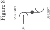
- the leading edge is the part of a blade that is in front.
- the trailing edge is behind.
- the trailing edge captures the wind in a drag turbine. It is a variation on a cup.
- (54) represents the direction of the wind hitting the trailing edge.
- the turbine faces the wind coming from 180 degrees, so that (55) is the right side and (56) the left.
- a lift turbine is like a wing, and moves not from the cupping of the fluid stream at the trailing edge, but from aerodynamic effects of movement towards low-pressure zones created by the shape of the blade or wing. Therefore, lift and drag turbines have dissimilar structures.
- the turbines in this patent are drag vertical axis turbines. Therefore, they usually have a greater amount of solidity because they are cup-shaped instead of wing-shaped, and need to contain as much fluid flow as possible, in general.
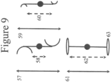
- Figure 9 illustrates that. (57), (59), and (61) are turbine diameters. (58), (60), and (62) are the open spaces between the blades, which is generally much less in a drag turbine than a lift turbine and the solidity is the proportion of (57) minus (58) divided by (57), which is here around 80%.
- the solidity is the percentage of turbine blade that blocks the theoretical straight path of the fluid through the turbine.
- the ratio of diameter (59) minus open space (60) divided by (59) is much lower, around 40%. That low solidity means there will be less of a cluster effect from diversion of flow to the sides, We will exclude 20% solidity or below from this invention because of that. For the purpose of simplicity in explaining the diagrams, the impact of the shaft is ignored. Much lower solidity is usually present in lift vertical axis turbines. Their blades (63) are long and thin structures that create a wing-like lift effect. Here the open space (62) is almost equal to that of the diameter (61) so that the solidity is around 10%.
- Figure 1 illustrates a 3 bladed wind turbine of drag type (2) while spinning from the wind.
- the wind is coming form the left.
- Element (1) shows the scale of the wind speeds shown from the interaction of the turbine and the wind from lower to higher wind speed on the top. This was originally in color; for the sake of the patent figure rules, the relevant parts are numbered and discussed,
- Element (3) is a dotted line showing the diameter of the turbine. The turbine is shown rotating counterclockwise. Facing the direction of wind, point (4) is where the wind on the right has attained high speed after losing speed in the area of the turbine. It extends to around a 1 50-degree angle to the wind from the shaft of the turbine. Point (5) is the same on the left.
- the recovery of high speed to equal to or greater than the prevailing wind is about 0.05 to 0.25 times the turbine diameter from the outer part of the turbine in the plane perpendicular to the direction of wind at the axis of the turbine
- the recovery is at around a ratio of 0.4 to 0.6 times the turbine diameter in the plane perpendicular to the direction of wind at the axis of the turbine.
- Theoretical line (6) shows that the angle from the sides of the turbine where the wake of turbulent vortices (8 is the most intensive example) is present fans out at 1 5-30 degrees on both sides from the turbine.
- Point (7) is at the edge of an area of circular turbulence, where the wind vectors are just starting to straighten out. There is a similar interface downwind and to the right of the turbine. Since the wind becomes higher speed to the outside of points (4) and (5) in approximately the plane of the blades, those regions would be ideal for placing adjacent turbines that would experience higher wind speeds, and thus a greater production of electricity, than each turbine individually.
- Vertical axis turbines normally have the disadvantage of having to resist wind of the same speed on the return journey as their leading edges face the wind instead of the trailing edges capturing it; the figures here that show a wind farm operating as a system show how this disadvantage can be minimized by proper placement of turbines in relation to each other.
- the subject of wakes is also important for horizontal axis turbines, and it is here that we can adopt some approaches that apply to vertical axis turbines as well.
- the standard practice has been to separate horizontal axis turbines even in the same row perpendicular to the prevailing wind at 3-5 blade diameter's apart to avoid negative wake interactions.
- Figure 11 suggests two methods of bringing blades closer that apply to vertical axis turbines as well.
- the blades of turbines can be coordinated so that they are at different angles to the direction of wind at the same time.
- Figure 11 illustrates that with two horizontal axis turbines, (72) and (73) whose blades are at different angles at the same time. Their steering effects (the angling of the blades towards the wind) and the revolutions per minute can also affect the wakes.
- Another method is to use a flow deflection device, in any relationship to the turbines, whether upwind to affect the power or at right angles to block the wakes, as is shown in (74), in coordination with any of these methods. Using such methods, a distance between adjacent turbines of 2 blade diameters even for horizontal axis turbines could be achievable.
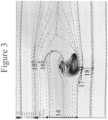
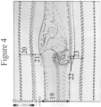
- Figures 2-4 show simulations of a single drag vertical axis wind turbine with different shapes at different vertical levels.
- the dotted lines (9), (14), (19) represent the diameter's of the turbines at various heights.
- Distances (11), (13), (16), (17), (21), and (22) show the distances from the edge of the turbine to the areas where the wind speed recovers to that of the prevailing speed.
- the blades of another wind turbine centered in the areas of (10), (12), (15), (18), (20), and (23) would reap the greatest benefit from the area of wind that is greater than the prevailing speed. After the outer points of areas (10), (12), (15), (18), (20), and (23), the wind descends to prevailing speed.
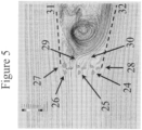
- Figure 5 shows the grouping of a single row of turbines that are all rotating in the same direction, in this case counterclockwise.
- Turbine 1 is (24)
- Turbine 2 is (25)
- Turbine 3 is (26).
- Points (27) and (28) are where the wind speed recovers to the prevailing wind speed or higher, and would be the points at which it would be ideal to place the edge of an adjacent wind turbine.
- the combination of similar turbines in a row achieves the displacement of the area of circular turbulence farther downwind from the first row of turbines than what occurred with one turbine alone, and allows room for a second row of turbines downwind from the first, whose blades can take advantage of funneled wind between the turbines at points 29 and 30.
- Points (31) and (32) show the boundary between the turbulent wind and the higher speed non-turbulent wind.
- the angle is much less than with one turbine alone (6). This means that, especially in an area where the wind is coming mostly from one direction, or where there are restrictions in the areas available to place the turbines, the ideal placement is either side by side in a single row, or each one downstream from the other very slightly to the side.
- Figure 6 shows two rows of three turbines each, (33) to (38). Dotted lines (40) and (41) show that the area of circular turbulence and lower wind speed becomes even more confined downwind with two rows of turbines.
- Turbine (38) benefits from a concentration of wind speed from stream (42).
- Turbine (36) benefits from stream (43).
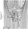
- Figure 7 shows two rows of turbines (44) to (49), (44), (46), and (48) are rotating counterclockwise, (45), (47), and (49) are rotating clockwise in an alternating pattern. This appears to be overall an inferior approach.
- the angles of lines (50) and (51) are much larger. Much more space is occupied by lower speed vortices.
- Streams (52) and (53) show that the second row still benefits, but not as much.
- counter-rotation only makes sense for the outer turbine-on the right when most turbines are counterclockwise, and on the left when most are clockwise. This shows clearly that the prior art referring to counter-rotation is irrelevant to drag turbines.
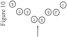
- FIG. 10 shows a modified V arrangement.
- the first row (67, 68) has more than one turbine, because doing so confines the area of vortices more than one turbine.
- the ideal formula for distance from the shaft of one turbine to the edge of the next, claimed for all turbines in a farm, in the embodiments of the first row or any two adjacent turbines in any row or from row to row, is the radius times 1.2, ranging from 1.05 to 1.6. In one embodiment, this applies to solidity (referring to the cross-sectional area covered by the blades) of 50% or greater. In another embodiment, it applies to 20% or greater. In one embodiment, this applies to turbines of diameter 1-5 meters. Another way to define it is a distance of separation of 0.2 meters plus or minus 10% from the edge of closest positions of cupped blades on two turbines. In another embodiment, the adjacent turbines counter-rotate within a row. in another embodiment, the adjacent drag turbines between one row and another counter-rotate.
- a microprocessor controls the coordination of the blade positions and/or orientations of adjacent turbines in a wind farm for maximal output. This was discussed above for horizontal axis turbines, but is also novel for vertical axis turbines. In another embodiment, the above configurations are placed on a rooftop. An embodiment is the placement of turbines of different type adjacent to each other. For example a 3-bladed drag vertical axis turbine could coordinate improved power output with a 2-bladed lift vertical axis turbine.
Landscapes
- Engineering & Computer Science (AREA)
- Life Sciences & Earth Sciences (AREA)
- Sustainable Development (AREA)
- Sustainable Energy (AREA)
- Chemical & Material Sciences (AREA)
- Combustion & Propulsion (AREA)
- Mechanical Engineering (AREA)
- General Engineering & Computer Science (AREA)
- Physics & Mathematics (AREA)
- Fluid Mechanics (AREA)
- Wind Motors (AREA)
Claims (10)
- Système d'une pluralité de turbines à axe vertical comprenant des arbres centraux et des pales périphériques,
chaque turbine comprenant un arbre et au moins une pale courbée et en forme de coupe du type drag incluant une partie d'attaque et une partie de fuite, le type drag étant défini comme une pale qui ressemble à une tasse plutôt qu'à un profil d'aile, comprenant :chaque dite turbine fixée à un emplacement,une turbine désignée comme Turbine 1, un turbine de type drag à rotation dans le sens des aiguilles d'une montre ou dans le sens inverse des aiguilles d'une montre, ladite turbine ayant une solidité de 20% ou plus, la solidité étant le pourcentage des pales de turbine qui bloquent le chemin droit théorique du vent à travers la turbine,une turbine désignée comme Turbine 2, dont le périmètre, quand il est le plus prêt du périmètre de la Turbine 1, est situé à une distance de l'arbre de la Turbine 1 du rayon de la Turbine 1 fois approximativement 1,05-1,6, la turbine 2 disposée dans une relation de 35-90° par rapport à la Turbine 1 en face d'un écoulement de fluide venant de 180 degrés à tout moment dans son orientation d'écoulement, dans lequel les Turbines 1 et 2 ont le même diamètre de turbine,chaque turbine a une variation de diamètre sur sa hauteur de telle manière qu'elle est une turbine conique et une variation de forme sur sa longueur de telle manière qu'à la même distance de l'arbre de chaque turbine à diverses hauteurs se trouve un emplacement qui subit une augmentation de la vitesse de vent du fait de l'interaction du vent avec chaque turbine permettant le groupement des Turbines 1 et 2, l'une des turbines étant placée de telle manière qu'elle bénéficie de l'augmentation de la vitesse du vent due à l'autre turbine. - Système selon la revendication 1, dans lequel les Turbines 1 et 2 tournent dans la même direction (33 et 34).
- Système selon la revendication 1, dans lequel les Turbines 1 et 2 tournent dans des directions opposées (45 et 46).
- Procédé de placement de turbines à axe vertical, chaque turbine comprenant un arbre et au moins une pale courbée et en forme de coupe du type drag incluant une partie d'attaque et une partie de fuite, dans un écoulement, comprenant les étapes de :fournir une turbine l,fixe à un emplacement, une turbine de type drag à rotation dans le sens des aiguilles d'une montre ou dans le sens inverse des aiguilles d'une montre, ladite turbine ayant une solidité de 20% ou plus, la solidité étant le pourcentage des pales de turbine qui bloquent le chemin droit théorique du vent à travers la turbine,fournir une Turbine 2, située à une distance fixe de la Turbine 1, dont le périmètre, quand il est le plus prêt du périmètre de la Turbine 1, est situé à une distance de l'arbre de la Turbine 1 du rayon de la Turbine 1 fois approximativement 1,05-1,6, la turbine 2 disposée dans une relation de 35-90° par rapport à la Turbine 1 en face d'un écoulement de fluide venant de 180 degrés à tout moment dans son orientation d'écoulement, dans lequel les Turbines 1 et 2 ont le même diamètre de turbine,chaque turbine a une variation de diamètre sur sa hauteur de telle manière qu'elle est une turbine conique et une variation de forme sur sa longueur de telle manière qu'à la même distance de l'arbre de chaque turbine à diverses hauteurs se trouve un emplacement qui subit une augmentation de la vitesse de vent du fait de l'interaction du vent avec chaque turbine permettant le groupement des Turbines 1 et 2, l'une des turbines étant placée de telle manière qu'elle bénéficie de l'augmentation de la vitesse du vent due à l'autre turbine.
- Procédé selon la revendication 4, comprenant en outre : de placer un dispositif de déviation d'écoulement adjacent à l'une quelconque des turbines.
- Procédé selon la revendication 4, dans lequel la direction du vent est définie comme s'écoulant de 180 degrés à zéro degrés, dans lequel la Turbine 1 tourne dans le sens inverse des aiguilles d'une montre et la Turbine 2 tourne dans le sens inverse des aiguilles d'une montre, et la turbine 2 est située à gauche de la Turbine 1 faisant face au vent (33 et 34), ou la Turbine 2 tourne dans le sens des aiguilles d'une montre (45) et est située à droite de la Turbine 1 faisant face au vent, ou la Turbine 1 tourne dans le sens des aiguilles d'une montre et la Turbine 2 tourne dans le sens des aiguilles d'une montre et est située à droite de la Turbine 1 faisant face au vent, ou la Turbine 1 tourne dans le sens des aiguilles d'une montre et la Turbine 2 tourne dans le sens des aiguilles d'une montre et est située à droite de la Turbine 1 faisant face au vent.
- Procédé selon la revendication 4, comprenant en outre de placer la Turbine 2 (49) de telle manière qu'au moins une partie de son au moins une partie d'attaque de pale courbée est en aval de la Turbine 1 (46) dans une zone de turbulence circulaire en aval de la Turbine 1.
- Procédé selon la revendication 4, dans lequel la direction du vent est définie comme s'écoulant de 180 degrés à zéro degrés, comprenant :de placer la Turbine 2 dans une première rangée adjacente à la Turbine 1, la Turbine 2 située à approximativement 270 degrés de la Turbine 1, une Turbine 3 placée dans une seconde rangée, en aval, entre, et sur le côté des Turbines 1 et 2, dans lequel les Turbines 1 et 2 tournent dans le sens inverse des aiguilles d'une montre (34 et 35), et la Turbine 3 est entre zéro et 180 degrés de la Turbine 2 et tourne dans le sens des aiguilles d'une montre, ou la Turbine 3 est entre 180 et zéro degrés de la Turbine 1 et la Turbine 3 tourne dans le sens inverse des aiguilles d'une montre (36),ou les Turbines 1 et 2 tournent dans le sens des aiguilles d'une montre, et la Turbine 3 est entre 180 et zéro degrés de la Turbine 1 et tourne dans le sens inverse des aiguilles d'une montre, ou la Turbine 3 est entre zéro et 180 degrés de la Turbine 2 et tourne dans le sens des aiguilles d'une montre,dans lequel le bord de fuite des pales de la Turbine 3 est de manière prédominante dans la région de vitesse de vent dominant sur le côté et en aval des Turbines 1 et 2 (36 et 43), et le bord d'attaque des pales de la Turbine 3 est de manière prédominante dans une région de turbulence circulaire sur le côté et en aval des Turbines 1 et 2 (36).
- Procédé selon la revendication 4, comprenant les étapes supplémentaires de fournir à un microprocesseur de la mémoire qui reçoit des informations sur au moins les positions de pales des turbines sur leurs axes de rotation et une vitesse et une direction de vent, de coordonner au moyen de la sortie du microprocesseur la position des pales de la Turbine 1 et la position des pales de la Turbine 2 selon leurs rotations l'une par rapport à l'autre, pour maximiser fonctionnellement l'apport d'une grande vitesse de vent de l'une à l'autre (72 et 73).
- Procédé selon la revendication 4, comprenant : de placer la Turbine 1 dans une première rangée, dans lequel la Turbine 1 produit une région voisine de plus grande vitesse de vent sur ses côtés quand elle fait face à une direction d'écoulement, la Turbine 2 est située de telle manière qu'au moins la moitié du diamètre de la Turbine 2 est placé dans la région de plus grande vitesse de vent adjacente à la Turbine 1, et ladite zone de plus grande vitesse de vent est orientée vers les bords de fuite de l'au moins une pale de la Turbine 2 (24, 25, 26; 38 et 42).
Applications Claiming Priority (2)
| Application Number | Priority Date | Filing Date | Title |
|---|---|---|---|
| US201462001103P | 2014-05-21 | 2014-05-21 | |
| PCT/IL2015/050537 WO2015177798A1 (fr) | 2014-05-21 | 2015-05-21 | Regroupement de turbines à axe vertical |
Publications (4)
| Publication Number | Publication Date |
|---|---|
| EP3146203A1 EP3146203A1 (fr) | 2017-03-29 |
| EP3146203A4 EP3146203A4 (fr) | 2017-10-18 |
| EP3146203B1 true EP3146203B1 (fr) | 2024-07-31 |
| EP3146203C0 EP3146203C0 (fr) | 2024-07-31 |
Family
ID=54553519
Family Applications (1)
| Application Number | Title | Priority Date | Filing Date |
|---|---|---|---|
| EP15796413.1A Active EP3146203B1 (fr) | 2014-05-21 | 2015-05-21 | Regroupement de turbines à axe vertical |
Country Status (5)
| Country | Link |
|---|---|
| US (1) | US10330086B2 (fr) |
| EP (1) | EP3146203B1 (fr) |
| CN (1) | CN106460789B (fr) |
| ES (1) | ES2989843T3 (fr) |
| WO (1) | WO2015177798A1 (fr) |
Families Citing this family (8)
| Publication number | Priority date | Publication date | Assignee | Title |
|---|---|---|---|---|
| US20170107975A1 (en) * | 2015-10-19 | 2017-04-20 | Wind Harvest International, Inc. | Vertical and Geographical Placements of Arrays of Vertical-Axis Wind-Turbines |
| CN116263143A (zh) * | 2021-12-13 | 2023-06-16 | 胥宝熙 | 快风家用风力发电机 |
| JP2025506565A (ja) | 2022-02-08 | 2025-03-11 | フラワー ターバインズ インコーポレイテッド | 流体タービン群を動作させるためのシステムおよび方法 |
| CN119452163A (zh) | 2022-04-12 | 2025-02-14 | 马克·丹尼尔·法博 | 用于操作流体涡轮机集群的系统和方法 |
| WO2024050317A1 (fr) | 2022-08-28 | 2024-03-07 | Flower Turbines, Inc. | Systèmes et procédés servant à faire fonctionner un groupe de turbines à fluide |
| CN119895139A (zh) | 2022-09-18 | 2025-04-25 | 花卉涡轮机股份有限公司 | 用于涡轮轴的套筒 |
| WO2024151908A2 (fr) | 2023-01-15 | 2024-07-18 | Mark Daniel Farb | Systèmes et procédés pour opérations de turbine à fluide |
| CN121311675A (zh) | 2023-04-09 | 2026-01-09 | 花卉涡轮机股份有限公司 | 流体涡轮机操作系统和方法 |
Citations (1)
| Publication number | Priority date | Publication date | Assignee | Title |
|---|---|---|---|---|
| US20140010654A1 (en) * | 2012-06-11 | 2014-01-09 | Bluenergy Solarwind, Inc. | Novel turbine blade and turbine assembly |
Family Cites Families (16)
| Publication number | Priority date | Publication date | Assignee | Title |
|---|---|---|---|---|
| US1697574A (en) * | 1924-12-12 | 1929-01-01 | Savonius Sigurd Johannes | Rotor adapted to be driven by wind or flowing water |
| US4359311A (en) * | 1981-05-26 | 1982-11-16 | Benesh Alvin H | Wind turbine rotor |
| US4830570A (en) * | 1987-12-15 | 1989-05-16 | Benesh Alvin H | Wind turbine system using twin savonius-type rotors |
| US5494407A (en) * | 1994-12-16 | 1996-02-27 | Benesh; Alvin H. | Wind turbine with savonius-type rotor |
| US6784566B2 (en) * | 2001-01-25 | 2004-08-31 | Robert Nason Thomas | Coupled vortex vertical axis wind turbine |
| CA2546750C (fr) * | 2002-12-02 | 2012-04-03 | Hans-Armin Ohlmann | Eolienne a axe vertical |
| US7811060B2 (en) * | 2006-03-13 | 2010-10-12 | Vanderhye Robert A | VAWT cluster and individual supporting arrangements |
| US8333561B2 (en) * | 2006-04-17 | 2012-12-18 | Richard Baron | Vertical axis wind turbine |
| WO2008092191A1 (fr) * | 2007-02-01 | 2008-08-07 | Water Un Limited | Éolienne |
| US20120207600A1 (en) * | 2009-10-21 | 2012-08-16 | Technip France | Floating vertical axis wind turbine module system and method |
| PL2536946T3 (pl) * | 2010-02-17 | 2016-03-31 | Spinetic Energy Ltd | Układ turbin wiatrowych |
| CN102650264A (zh) * | 2011-02-23 | 2012-08-29 | 曾锦炼 | 一种并联矩阵整合型风力发电系统 |
| WO2013025568A2 (fr) * | 2011-08-12 | 2013-02-21 | California Institute Of Technology | Procédés et systèmes pour comparer des groupes de turbines à axe vertical et pour établir leurs configurations |
| US20140099203A1 (en) * | 2012-10-04 | 2014-04-10 | Wind Harvest International, Inc. | Mechanical and other improvements of a vertical axis wind turbine |
| DE202013003148U1 (de) * | 2013-04-07 | 2013-06-11 | Sinusstrom GmbH | Flügelelement für einen Savonius-Rotor, Savonius-Rotor und Kleinwindkraftanlage |
| US20170107975A1 (en) * | 2015-10-19 | 2017-04-20 | Wind Harvest International, Inc. | Vertical and Geographical Placements of Arrays of Vertical-Axis Wind-Turbines |
-
2015
- 2015-05-21 ES ES15796413T patent/ES2989843T3/es active Active
- 2015-05-21 EP EP15796413.1A patent/EP3146203B1/fr active Active
- 2015-05-21 WO PCT/IL2015/050537 patent/WO2015177798A1/fr not_active Ceased
- 2015-05-21 CN CN201580026019.6A patent/CN106460789B/zh active Active
- 2015-05-21 US US15/310,770 patent/US10330086B2/en active Active
Patent Citations (1)
| Publication number | Priority date | Publication date | Assignee | Title |
|---|---|---|---|---|
| US20140010654A1 (en) * | 2012-06-11 | 2014-01-09 | Bluenergy Solarwind, Inc. | Novel turbine blade and turbine assembly |
Also Published As
| Publication number | Publication date |
|---|---|
| CN106460789A (zh) | 2017-02-22 |
| EP3146203A1 (fr) | 2017-03-29 |
| US10330086B2 (en) | 2019-06-25 |
| EP3146203C0 (fr) | 2024-07-31 |
| US20170089326A1 (en) | 2017-03-30 |
| CN106460789B (zh) | 2019-07-05 |
| WO2015177798A1 (fr) | 2015-11-26 |
| EP3146203A4 (fr) | 2017-10-18 |
| ES2989843T3 (es) | 2024-11-27 |
Similar Documents
| Publication | Publication Date | Title |
|---|---|---|
| EP3146203B1 (fr) | Regroupement de turbines à axe vertical | |
| US20230250797A1 (en) | Fluid turbine systems | |
| US9255567B2 (en) | Two-bladed vertical axis wind turbines | |
| CN102057157B (zh) | 风力涡轮机 | |
| CN104169574B (zh) | 涡轮机 | |
| US20170306925A1 (en) | Three-vane double rotor for vertical axis turbine | |
| US9551318B2 (en) | HVATA-hybrid vertical axis turbine assembly operable under omni-directional flow for power generating systems | |
| US11015580B2 (en) | Crossflow axes rotary mechanical devices with dynamic increased swept area | |
| WO2015058689A1 (fr) | Ensemble d'aube pour machine à dynamique des fluides et dispositif de propulsion | |
| WO2016059439A1 (fr) | Éolienne à axe vertical | |
| BR112016026981B1 (pt) | Agrupamento de turbinas de eixo vertical | |
| EP2323901A2 (fr) | Pales hybrides de turbine à axe vertical | |
| WO2017096460A1 (fr) | Éolienne à pales articulées |
Legal Events
| Date | Code | Title | Description |
|---|---|---|---|
| STAA | Information on the status of an ep patent application or granted ep patent |
Free format text: STATUS: THE INTERNATIONAL PUBLICATION HAS BEEN MADE |
|
| PUAI | Public reference made under article 153(3) epc to a published international application that has entered the european phase |
Free format text: ORIGINAL CODE: 0009012 |
|
| STAA | Information on the status of an ep patent application or granted ep patent |
Free format text: STATUS: REQUEST FOR EXAMINATION WAS MADE |
|
| 17P | Request for examination filed |
Effective date: 20161230 |
|
| AK | Designated contracting states |
Kind code of ref document: A1 Designated state(s): AL AT BE BG CH CY CZ DE DK EE ES FI FR GB GR HR HU IE IS IT LI LT LU LV MC MK MT NL NO PL PT RO RS SE SI SK SM TR |
|
| AX | Request for extension of the european patent |
Extension state: BA ME |
|
| RIC1 | Information provided on ipc code assigned before grant |
Ipc: F03D 80/00 20160101ALI20170613BHEP Ipc: F03D 3/06 20060101ALI20170613BHEP Ipc: F03D 9/00 20160101ALI20170613BHEP Ipc: F03D 3/02 20060101ALI20170613BHEP Ipc: F03D 7/06 20060101ALI20170613BHEP Ipc: F03D 3/00 20060101AFI20170613BHEP |
|
| DAV | Request for validation of the european patent (deleted) | ||
| DAX | Request for extension of the european patent (deleted) | ||
| A4 | Supplementary search report drawn up and despatched |
Effective date: 20170920 |
|
| RIC1 | Information provided on ipc code assigned before grant |
Ipc: F03D 7/06 20060101ALI20170914BHEP Ipc: F03D 80/00 20160101ALI20170914BHEP Ipc: F03D 9/00 20160101ALI20170914BHEP Ipc: F03D 3/06 20060101ALI20170914BHEP Ipc: F03D 3/02 20060101ALI20170914BHEP Ipc: F03D 3/00 20060101AFI20170914BHEP |
|
| STAA | Information on the status of an ep patent application or granted ep patent |
Free format text: STATUS: EXAMINATION IS IN PROGRESS |
|
| 17Q | First examination report despatched |
Effective date: 20190102 |
|
| GRAP | Despatch of communication of intention to grant a patent |
Free format text: ORIGINAL CODE: EPIDOSNIGR1 |
|
| STAA | Information on the status of an ep patent application or granted ep patent |
Free format text: STATUS: GRANT OF PATENT IS INTENDED |
|
| INTG | Intention to grant announced |
Effective date: 20240229 |
|
| GRAS | Grant fee paid |
Free format text: ORIGINAL CODE: EPIDOSNIGR3 |
|
| GRAA | (expected) grant |
Free format text: ORIGINAL CODE: 0009210 |
|
| STAA | Information on the status of an ep patent application or granted ep patent |
Free format text: STATUS: THE PATENT HAS BEEN GRANTED |
|
| AK | Designated contracting states |
Kind code of ref document: B1 Designated state(s): AL AT BE BG CH CY CZ DE DK EE ES FI FR GB GR HR HU IE IS IT LI LT LU LV MC MK MT NL NO PL PT RO RS SE SI SK SM TR |
|
| REG | Reference to a national code |
Ref country code: CH Ref legal event code: EP Ref country code: GB Ref legal event code: FG4D |
|
| REG | Reference to a national code |
Ref country code: DE Ref legal event code: R096 Ref document number: 602015089385 Country of ref document: DE |
|
| REG | Reference to a national code |
Ref country code: IE Ref legal event code: FG4D |
|
| U01 | Request for unitary effect filed |
Effective date: 20240821 |
|
| U07 | Unitary effect registered |
Designated state(s): AT BE BG DE DK EE FI FR IT LT LU LV MT NL PT RO SE SI Effective date: 20240902 |
|
| REG | Reference to a national code |
Ref country code: ES Ref legal event code: FG2A Ref document number: 2989843 Country of ref document: ES Kind code of ref document: T3 Effective date: 20241127 |
|
| PG25 | Lapsed in a contracting state [announced via postgrant information from national office to epo] |
Ref country code: PL Free format text: LAPSE BECAUSE OF FAILURE TO SUBMIT A TRANSLATION OF THE DESCRIPTION OR TO PAY THE FEE WITHIN THE PRESCRIBED TIME-LIMIT Effective date: 20240731 Ref country code: GR Free format text: LAPSE BECAUSE OF FAILURE TO SUBMIT A TRANSLATION OF THE DESCRIPTION OR TO PAY THE FEE WITHIN THE PRESCRIBED TIME-LIMIT Effective date: 20241101 |
|
| PG25 | Lapsed in a contracting state [announced via postgrant information from national office to epo] |
Ref country code: IS Free format text: LAPSE BECAUSE OF FAILURE TO SUBMIT A TRANSLATION OF THE DESCRIPTION OR TO PAY THE FEE WITHIN THE PRESCRIBED TIME-LIMIT Effective date: 20241130 |
|
| PG25 | Lapsed in a contracting state [announced via postgrant information from national office to epo] |
Ref country code: HR Free format text: LAPSE BECAUSE OF FAILURE TO SUBMIT A TRANSLATION OF THE DESCRIPTION OR TO PAY THE FEE WITHIN THE PRESCRIBED TIME-LIMIT Effective date: 20240731 |
|
| PG25 | Lapsed in a contracting state [announced via postgrant information from national office to epo] |
Ref country code: RS Free format text: LAPSE BECAUSE OF FAILURE TO SUBMIT A TRANSLATION OF THE DESCRIPTION OR TO PAY THE FEE WITHIN THE PRESCRIBED TIME-LIMIT Effective date: 20241031 |
|
| PG25 | Lapsed in a contracting state [announced via postgrant information from national office to epo] |
Ref country code: RS Free format text: LAPSE BECAUSE OF FAILURE TO SUBMIT A TRANSLATION OF THE DESCRIPTION OR TO PAY THE FEE WITHIN THE PRESCRIBED TIME-LIMIT Effective date: 20241031 Ref country code: PL Free format text: LAPSE BECAUSE OF FAILURE TO SUBMIT A TRANSLATION OF THE DESCRIPTION OR TO PAY THE FEE WITHIN THE PRESCRIBED TIME-LIMIT Effective date: 20240731 Ref country code: IS Free format text: LAPSE BECAUSE OF FAILURE TO SUBMIT A TRANSLATION OF THE DESCRIPTION OR TO PAY THE FEE WITHIN THE PRESCRIBED TIME-LIMIT Effective date: 20241130 Ref country code: HR Free format text: LAPSE BECAUSE OF FAILURE TO SUBMIT A TRANSLATION OF THE DESCRIPTION OR TO PAY THE FEE WITHIN THE PRESCRIBED TIME-LIMIT Effective date: 20240731 Ref country code: GR Free format text: LAPSE BECAUSE OF FAILURE TO SUBMIT A TRANSLATION OF THE DESCRIPTION OR TO PAY THE FEE WITHIN THE PRESCRIBED TIME-LIMIT Effective date: 20241101 |
|
| PG25 | Lapsed in a contracting state [announced via postgrant information from national office to epo] |
Ref country code: SM Free format text: LAPSE BECAUSE OF FAILURE TO SUBMIT A TRANSLATION OF THE DESCRIPTION OR TO PAY THE FEE WITHIN THE PRESCRIBED TIME-LIMIT Effective date: 20240731 |
|
| PG25 | Lapsed in a contracting state [announced via postgrant information from national office to epo] |
Ref country code: CZ Free format text: LAPSE BECAUSE OF FAILURE TO SUBMIT A TRANSLATION OF THE DESCRIPTION OR TO PAY THE FEE WITHIN THE PRESCRIBED TIME-LIMIT Effective date: 20240731 |
|
| PG25 | Lapsed in a contracting state [announced via postgrant information from national office to epo] |
Ref country code: SK Free format text: LAPSE BECAUSE OF FAILURE TO SUBMIT A TRANSLATION OF THE DESCRIPTION OR TO PAY THE FEE WITHIN THE PRESCRIBED TIME-LIMIT Effective date: 20240731 |
|
| PLBE | No opposition filed within time limit |
Free format text: ORIGINAL CODE: 0009261 |
|
| STAA | Information on the status of an ep patent application or granted ep patent |
Free format text: STATUS: NO OPPOSITION FILED WITHIN TIME LIMIT |
|
| 26N | No opposition filed |
Effective date: 20250501 |
|
| U21 | Renewal fee for the european patent with unitary effect paid with additional fee |
Year of fee payment: 11 Effective date: 20251020 |
|
| REG | Reference to a national code |
Ref country code: CH Ref legal event code: H13 Free format text: ST27 STATUS EVENT CODE: U-0-0-H10-H13 (AS PROVIDED BY THE NATIONAL OFFICE) Effective date: 20251223 |
|
| PGFP | Annual fee paid to national office [announced via postgrant information from national office to epo] |
Ref country code: GB Payment date: 20251128 Year of fee payment: 11 |
|
| PGFP | Annual fee paid to national office [announced via postgrant information from national office to epo] |
Ref country code: NO Payment date: 20251128 Year of fee payment: 11 |
|
| PG25 | Lapsed in a contracting state [announced via postgrant information from national office to epo] |
Ref country code: CH Free format text: LAPSE BECAUSE OF NON-PAYMENT OF DUE FEES Effective date: 20250531 |
|
| PG25 | Lapsed in a contracting state [announced via postgrant information from national office to epo] |
Ref country code: MC Free format text: LAPSE BECAUSE OF FAILURE TO SUBMIT A TRANSLATION OF THE DESCRIPTION OR TO PAY THE FEE WITHIN THE PRESCRIBED TIME-LIMIT Effective date: 20240731 |
|
| PGFP | Annual fee paid to national office [announced via postgrant information from national office to epo] |
Ref country code: ES Payment date: 20251128 Year of fee payment: 11 |
|
| PG25 | Lapsed in a contracting state [announced via postgrant information from national office to epo] |
Ref country code: IE Free format text: LAPSE BECAUSE OF NON-PAYMENT OF DUE FEES Effective date: 20250521 |