EP3146535B1 - Leitungsdurchführung - Google Patents
Leitungsdurchführung Download PDFInfo
- Publication number
- EP3146535B1 EP3146535B1 EP15722185.4A EP15722185A EP3146535B1 EP 3146535 B1 EP3146535 B1 EP 3146535B1 EP 15722185 A EP15722185 A EP 15722185A EP 3146535 B1 EP3146535 B1 EP 3146535B1
- Authority
- EP
- European Patent Office
- Prior art keywords
- force
- insulating body
- force transmission
- housing
- motor
- Prior art date
- Legal status (The legal status is an assumption and is not a legal conclusion. Google has not performed a legal analysis and makes no representation as to the accuracy of the status listed.)
- Active
Links
Images


Classifications
-
- H—ELECTRICITY
- H02—GENERATION; CONVERSION OR DISTRIBUTION OF ELECTRIC POWER
- H02K—DYNAMO-ELECTRIC MACHINES
- H02K5/00—Casings; Enclosures; Supports
- H02K5/04—Casings or enclosures characterised by the shape, form or construction thereof
- H02K5/22—Auxiliary parts of casings not covered by groups H02K5/06-H02K5/20, e.g. shaped to form connection boxes or terminal boxes
- H02K5/225—Terminal boxes or connection arrangements
-
- F—MECHANICAL ENGINEERING; LIGHTING; HEATING; WEAPONS; BLASTING
- F04—POSITIVE - DISPLACEMENT MACHINES FOR LIQUIDS; PUMPS FOR LIQUIDS OR ELASTIC FLUIDS
- F04D—NON-POSITIVE-DISPLACEMENT PUMPS
- F04D13/00—Pumping installations or systems
- F04D13/02—Units comprising pumps and their driving means
- F04D13/06—Units comprising pumps and their driving means the pump being electrically driven
- F04D13/0693—Details or arrangements of the wiring
-
- F—MECHANICAL ENGINEERING; LIGHTING; HEATING; WEAPONS; BLASTING
- F04—POSITIVE - DISPLACEMENT MACHINES FOR LIQUIDS; PUMPS FOR LIQUIDS OR ELASTIC FLUIDS
- F04D—NON-POSITIVE-DISPLACEMENT PUMPS
- F04D29/00—Details, component parts, or accessories
- F04D29/02—Selection of particular materials
- F04D29/026—Selection of particular materials especially adapted for liquid pumps
-
- H—ELECTRICITY
- H02—GENERATION; CONVERSION OR DISTRIBUTION OF ELECTRIC POWER
- H02K—DYNAMO-ELECTRIC MACHINES
- H02K5/00—Casings; Enclosures; Supports
- H02K5/04—Casings or enclosures characterised by the shape, form or construction thereof
- H02K5/12—Casings or enclosures characterised by the shape, form or construction thereof specially adapted for operating in liquid or gas
- H02K5/132—Submersible electric motors
-
- H—ELECTRICITY
- H02—GENERATION; CONVERSION OR DISTRIBUTION OF ELECTRIC POWER
- H02K—DYNAMO-ELECTRIC MACHINES
- H02K7/00—Arrangements for handling mechanical energy structurally associated with dynamo-electric machines, e.g. structural association with mechanical driving motors or auxiliary dynamo-electric machines
- H02K7/14—Structural association with mechanical loads, e.g. with hand-held machine tools or fans
Definitions
- the invention relates to a device with a pump that is driven by a wet rotor motor and has a housing which comprises a bushing arrangement for supplying power to the wet rotor motor, the bushing arrangement having a line element and an integrally formed insulating body and comprising a holding element.
- Such devices are used, for example, in the reactor pressure vessel of a boiling water reactor, with a plug-in pump ensuring that the coolant is circulated without external pipelines.
- the housing parts form the pressure envelope, which delimits an interior space from the surrounding atmosphere.
- the push envelope is usually designed for a very high system pressure.
- the device comprises a pump which is driven by a liquid-filled motor.
- the motor has a housing which is part of the pressure envelope.
- the invention relates to a device with a pump which is driven by a wet rotor motor.
- wet rotor motors a distinction is made between designs with dry and wet winding of the stator. If the stator winding is dry, one speaks of a canned motor. A wet stator winding is referred to as a wet motor.
- the wet engine is completely filled with liquid. With the The rotor and its bearing, the stator and the winding including the supply line connections are also in the liquid. The prerequisite is a waterproof and pressure-tight insulation of all live parts.
- the wet motor is used in particular as a drive motor for glandless circulating pumps in power plants.
- the lead-through arrangement comprises two insulating bodies, an outer insulating body made of ceramic and an inner insulating body made of hard rubber.
- the DE 31 03 299 A1 describes a device with a glandless circulation pump driven by an electric motor.
- the housing designed as a pressure sleeve, has a feed-through arrangement for supplying power to the motor.
- the bushing arrangement comprises a line element designed as a conductor connection bolt and two insulating bodies, an inner ceramic insulating body and an outer insulating support body.
- the insulation is constructed in two parts. It consists of an inner insulating body and an outer insulating body.
- the inner insulating body is the pressure-bearing part.
- An outer insulating body is arranged over the inner insulating body.
- both insulating bodies require a very long overlap in order to achieve the necessary creepage distances. This increases the installation space.
- Metal rings are used to protect against high loads. These require additional sealing points and can be heated by eddy currents.
- the JP S55 15968 U describes an insulation element attached to a cable 7, which is passed through a cable lead-through opening of an electrical device main body.
- a flange-like projection is formed in a section of the insulation element which rests against a shoulder formed in the main body of the device and is fixed by means of a fastening sleeve.
- the object of the invention is to provide a device with a pump driven by a wet rotor motor, which ensures a high degree of safety and takes up as little space as possible. As few sealing points as possible should be required.
- the leadthrough arrangement comprises at least one force transmission element arranged between the holding element and the housing, on which the holding element fixed by fastening elements on the housing exerts a force which the force transmission element transmits to the housing and / or the insulating body, the force transmission element being fully integrated in the insulating body and consists of a high-strength fiber material embedded in a matrix to form a mechanical reinforcement.
- the force transmission element is preferably a mechanical reinforcement element made of an electrically non-conductive and / or non-magnetic material. This avoids eddy current losses and the associated heating.
- the holding element acts on the force transmission element and presses it in the direction of the housing.
- the insulating body surrounds the line element that supplies the wet rotor motor with power.
- the force transmission element is in operative connection with the insulating body and ensures that the insulating body is fixed on the housing.
- the device according to the invention enables a separation of tasks between insulation and power transmission, so that only one insulating body is required in the device according to the invention. This significantly reduces the installation space. In addition, the required sealing surfaces are reduced and secondary seals are avoided.
- the line element preferably has a thickening at the end directed towards the inside of the housing. It proves to be advantageous if the insulating body is braced between the fastening element and the thickening of the line element. In a particularly advantageous embodiment of the invention, the thickening is frustoconical.
- the power transmission element is pressed against the housing. This fixes the insulating body in the lead-through arrangement.
- the force transmission element and the insulating body are in operative connection with one another.
- the force transmission element has an area which protrudes into a feed-through opening in the housing. In this area, the force transmission element has an outer diameter which is somewhat smaller than the inner diameter of the opening in the housing. Sealing elements are preferably arranged in the area between the force transmission element and the motor housing.
- the force transmission element has an area which forms a stop for the feed-through opening in the housing.
- the force transmission element has both an area that protrudes into the lead-through opening in the housing and an area that is arranged outside the lead-through opening.
- the force transmission element is designed like a ring and encloses an area through which the line element passes.
- the smallest inside diameter of this area is preferably smaller than the largest outside diameter of the thickening of the line element. If the insulating body breaks, the high pressure in the motor housing pushes the line element "outwards". In this variant, the force transmission element forms a stop for the thickening of the line element.
- This construction secures the line element against a bullet-like leakage from the housing and prevents massive leakage along the line element. Leakage is preferably prevented in the normal state by sealing elements.
- the annular force transmission element is designed in the shape of a truncated cone and has an opening in the middle.
- the base of the ring-like frustoconical force transmission element faces the housing.
- the top surface faces the outside.
- the lateral surface faces the holding element. If the fastening elements are tightened on the holding element, the holding element acts on the outer surface of the force transmission element.
- the holding element preferably has a central frustoconical opening.
- the inclined inner surfaces of the holding element act on the inclined outer surfaces of the force transmission element.
- the holding element braces the force transmission element against the housing.
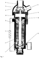
- Figure 1 shows a device designed as a motor-pump unit with a wet rotor motor 1.
- a motor housing 2 forms part of the pressure envelope.
- the inside of the wet rotor motor 1 is filled with liquid.
- a cooling system 3 is provided to dissipate the electrical power loss.
- the wet rotor motor 1 comprises radial and axial bearings.
- the driving force of the motor 1 acts on a shaft train 5 and thus transmits a torque to a pump 4.
- the pump 4 comprises a pump housing 6 in which an impeller 7 and a guide device 8 are arranged.
- the pump housing 6 is closed by a cover element 9 and connected to the motor housing 2 via at least one tie rod 10.
- flywheel 11 Within the cover element 9, which is constructed in several parts in the exemplary embodiment, there is a flywheel 11, the moment of inertia of which ensures further rotation of the shaft train 5 in the event of a power failure.
- the motor housing 2 and the pump housing 6 together with the cover element 9 form the pressure envelope. This is designed for a high system pressure.
- the unit is designed for a drive power greater than 600 kW.
- the wet rotor motor 1 is designed as a wet motor.
- the wet rotor motor 1 is completely filled with liquid. With the rotor and its bearing, the stator and the winding including the supply line connections are also in the liquid.
- a feed-through arrangement 12 is provided in the motor housing 2 for supplying power to the wet rotor motor 1.
- FIG. 2 shows a perspective sectional view of a leadthrough arrangement 12.
- the motor housing 2 has a leadthrough opening 13 for this purpose.
- the feed-through opening 13 is made as a bore in the motor housing 2.
- a line element 14 is used to supply power to the wet rotor motor 1.
- the line element 14 is designed as a cylindrical bolt.
- An insulating body 15 separates the line element 14 from the motor housing 2.
- the line element 14 has a thickening 16.
- the thickening 16 is designed like a truncated cone and faces the inside with the top surface.
- a cylindrical section of the line element 14 adjoins the base area of the frustoconical thickening 16.
- the line element 14 and the insulating body 15 are braced against one another.
- the line element 14 has an external thread onto which the component 17 is screwed.
- a force is exerted on the insulating body 13 via a disk 18 and presses it against the thickening 16 of the line element 14.
- the insulating body 15 rests against a contact surface 19 of the line element 14, which is formed by the thickening 16 of the line element 15.
- the leadthrough arrangement 12 has a force transmission element 20.
- the force transmission element 20 is designed as an annular truncated cone body.
- the force transmission element 20 is completely integrated in the insulating body 15.
- the leadthrough arrangement 12 comprises a holding element 21 which is fixed to the motor housing 2 by fastening elements 22 which are designed as screws.
- the holding element 21 is designed as an annular disc with a frustoconical central opening. Bores, in which the fastening elements 22 are arranged, are introduced along the circumference of the disk-like holding element 21. Bores 23 which have an internal thread are made in the motor housing 2.
- the fastening elements 22 have a corresponding external thread.
- the line element 14 has an opening 24 in the area of the thickening 16.
- a conductor 25 of the wet rotor motor 1 is arranged in this opening 24.
- the line element 14 and the conductor 25 are surrounded by insulation 26, which in the exemplary embodiment is designed as a shrink tube and / or insulating tape.
- the conductor 25 is a current-carrying cable from the winding of the wet rotor motor 1.
- the insulating body 15 is made in one piece and has an integral force transmission element 20.
- the force transmission element 20 is a mechanical reinforcement which brings about the introduction of force into the pressure envelope.
- the inner diameter of the ring-shaped force transmission element 20 is smaller than the outer diameter of the thickening 16 of the line element 14. If the insulating body 15 breaks, the line element 14 is secured against a bullet-like exit from the motor housing 2 by the force transmission element 20, thereby preventing massive leakage .
- the force transmission element 20 can consist of a high-strength fiber material which is embedded in a matrix. In this way a mechanical reinforcement is formed.
- the force transmission element 20 is inserted as an insert ring during the manufacture of the insulating body 15 and then, if necessary, encapsulated.
- the force transmission element 20 can be introduced into a space provided for this purpose by winding and / or gluing.
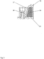
- FIG 3 shows an excerpt from Figure 2 shown variant.
- the ring-shaped force transmission element 20 has an outer jacket surface 27 which runs parallel to a surface 28 of the inner opening of the holding element 21.
- the surface 28 is an inner conical surface of the holding element 21.
- the ring-like force transmission element 20 has an end face 29 which is directed towards the motor housing 2 or towards the feed-through opening 13. Furthermore, the force transmission element 20 has an end face 30 which is directed outwards or towards the component 17.
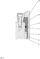
- Figure 4 shows a variant, which is not the subject of the claimed invention, in which the force transmission element 20 protrudes at least partially into the feed-through opening 13.
- the force transmission element 20 has a circumferential groove 31 in which an annular sealing element 32 is arranged.
- the force transmission element 20 has an extension 33 which is surrounded by an insulation layer 26.
- the extension 33 is sleeve-shaped.
- Figure 5 shows a variant, which is not the subject of the claimed invention, in which the force transmission element 20 is designed as an annular cylindrical disk or as a sleeve.
Landscapes
- Engineering & Computer Science (AREA)
- Power Engineering (AREA)
- Mechanical Engineering (AREA)
- General Engineering & Computer Science (AREA)
- Structures Of Non-Positive Displacement Pumps (AREA)
- Connection Of Motors, Electrical Generators, Mechanical Devices, And The Like (AREA)
Description
- Die Erfindung betrifft eine Vorrichtung mit einer Pumpe, die von einem Nassläufermotor angetrieben wird und ein Gehäuse aufweist, das eine Durchführungsanordnung zur Stromversorgung des Nassläufermotors umfasst, wobei die Durchführungsanordnung ein Leitungselement und einen einstückig ausgebildeten Isolierkörper aufweist und ein Halteelement umfasst.
- Solche Vorrichtungen werden beispielsweise im Reaktordruckgefäß eines Siedewasserreaktors eingesetzt, wobei eine Einsteckpumpe für die Umwälzung des Kühlmittels ohne externe Rohrleitungen sorgt. Die Gehäuseteile bilden die Druckhülle, die einen Innenraum gegenüber einer umgebenden Atmosphäre begrenzt. Die Drückhülle ist meist für einen sehr hohen Systemdruck ausgelegt.
- In der
EP 1 910 685 B1 wird eine solche Vorrichtung beschrieben. Die Vorrichtung umfasst eine Pumpe, die von einem flüssigkeitsgefüllten Motor angetrieben wird. Der Motor weist ein Gehäuse auf, welches Teil der Druckhülle ist. - Die Erfindung betrifft eine Vorrichtung mit einer Pumpe, die von einem Nassläufermotor angetrieben wird. Bei Nassläufermotoren unterscheidet man Ausführungen mit trockener und nasser Wicklung des Stators. Bei einer trockenen Wicklung des Stators spricht man von einem Spaltrohrmotor. Bei einer nassen Wicklung des Stators spricht man von einem nassen Motor. Der nasse Motor ist vollständig mit Flüssigkeit gefüllt. Mit dem Läufer und seiner Lagerung liegen auch der Stator und die Wicklung einschließlich der Zuleitungsanschlüsse in der Flüssigkeit. Voraussetzung ist eine wasserfeste und druckdichte Isolation aller spannungsführenden Teile. Der nasse Motor wird insbesondere als Antriebmotor für stopfbuchslose Umwälzpumpen in Kraftwerken eingesetzt.
- In der
DE 31 00 863 A1 wird eine Abdichtung für eine Leitungsdurchführung zu einem druckbeaufschlagten Raum beschrieben, in dem ein Elektromotor zum Antrieb einer stopfbuchslosen Umwälzpumpe angeordnet ist. Dabei werden ein als Leiteranschlussbolzen ausgeführtes Leitungselement und ein Isolierkörper gegeneinander verspannt. Die Durchführungsanordnung umfasst zwei Isolierkörper, einen äußeren Isolationskörper aus Keramik und einen inneren Isolationskörper aus Hartgummi. - Die
DE 31 03 299 A1 beschreibt eine Vorrichtung mit einer stopfbuchslosen Umwälzpumpe, die von einem Elektromotor angetrieben wird. Das als Druckhülle ausgebildete Gehäuse weist eine Durchführungsanordnung zur Stromversorgung des Motors auf. Die Durchführungsanordnung umfasst ein als Leiteranschlussbolzen ausgebildetes Leitungselement und zwei Isolierkörper, einen inneren Keramikisolierkörper und einen äußeren isolierenden Stützkörper. - Bei diesen herkömmlichen Durchführungsanordnungen zur Stromversorgung von Nassläufermotoren ist die Isolierung zweiteilig aufgebaut. Sie besteht aus einem inneren Isolierkörper und einem äußeren Isolierkörper. Der innere Isolierkörper ist der drucktragende Teil. Über den inneren Isolierkörper wird ein äußerer Isolierkörper angeordnet. Im Zusammenspiel benötigen beide Isolierkörper eine sehr lange Überdeckung, um die notwendigen Kriechstrecken zu erreichen. Dies vergrößert den Bauraum. Bei hohen Belastungen werden zur Absicherung Metallringe verwendet. Diese erfordern weitere Dichtstellen und können sich durch Wirbelströme erwärmen.
- Aus der
US 3,043,903 A ist eine Durchführungsanordnung bekannt, die einen einzigen, einen Stromleiter umschließenden Isolierkörper aufweist. - Die
JP S55 15968 U - In der
GB 2 003 334 A - Aufgabe der Erfindung ist es eine Vorrichtung mit einer von einem Nassläufermotor angetriebenen Pumpe bereitzustellen, die ein hohes Maß an Sicherheit gewährleistet und einen möglichst geringen Bauraum einnimmt. Dabei sollen möglichst wenige Dichtstellen erforderlich sein.
- Diese Aufgabe wird erfindungsgemäß durch eine Vorrichtung mit den Merkmalen des Anspruchs 1 gelöst. Bevorzugte Varianten sind in den Unteransprüchen ausgeführt.
- Erfindungsgemäß umfasst die Durchführungsanordnung mindestens ein zwischen dem Halteelement und dem Gehäuse angeordnetes Kraftübertragungselement, auf welches das durch Befestigungselemente am Gehäuse festgelegte Halteelement eine Kraft ausübt, die das Kraftübertragungselement auf das Gehäuse und/oder den Isolierkörper überträgt, wobei das Kraftübertragungselement vollständig in dem Isolierkörper integriert ist und zur Bildung einer mechanischen Verstärkung aus einem hochfesten in einer Matrix eingebetteten Faserwerkstoff besteht.
- Vorzugsweise handelt es sich bei dem Kraftübertragungselement um ein mechanisches Verstärkungselement aus einem elektrisch nicht leitenden und/oder nicht magnetischen Material. Dadurch werden Wirbelstromverluste und damit verbundene Erwärmungen vermieden.
- Das Halteelement wirkt auf das Kraftübertragungselement und drückt dieses in Richtung des Gehäuses.
- Der Isolierkörper umgibt das Leitungselement, welches den Nassläufermotor mit Strom versorgt. Das Kraftübertragungselement steht mit dem Isolierkörper in Wirkverbindung und sorgt für eine Fixierung des Isolierkörpers am Gehäuse.
- Die erfindungsgemäße Vorrichtung ermöglicht eine Aufgabentrennung zwischen Isolierung und Kraftübertragung, so dass bei der erfindungsgemäßen Vorrichtung nur ein Isolierkörper erforderlich ist. Dadurch wird der Bauraum deutlich verkleinert. Zudem werden die erforderlichen Dichtflächen reduziert und Sekundärdichtungen vermieden.
- Bevorzugt weist das Leitungselement eine Verdickung an dem zur Innenseite des Gehäuses gerichteten Ende auf. Dabei erweist es sich als günstig, wenn der Isolierkörper zwischen dem Befestigungselement und der Verdickung des Leitungselements verspannt ist. Bei einer besonders vorteilhaften Ausführung der Erfindung ist die Verdickung kegelstumpfförmig ausgebildet.
- Das Kraftübertragungselement wird gegen das Gehäuse gedrückt. Dadurch wird der Isolierkörper in der Durchführungsanordnung fixiert. Das Kraftübertragungselement und der Isolierkörper stehen in Wirkverbindung miteinander.
- Bei einer Variante der Erfindung weist das Kraftübertragungselement einen Bereich auf, der in eine Durchführungsöffnung im Gehäuse hineinragt. Das Kraftübertragungselement weist in diesem Bereich einen Außendurchmesser auf, der etwas kleiner ist als der Innendurchmesser der Öffnung im Gehäuse. Vorzugsweise sind in dem Bereich zwischen dem Kraftübertragungselement und dem Motorgehäuse Dichtelemente angeordnet.
- Bei einer Variante der Erfindung weist das Kraftübertragungselement einen Bereich auf, der einen Anschlag zu der Durchführungsöffnung im Gehäuse bildet. Vorzugsweise weist dabei das Kraftübertragungselement sowohl einen Bereich auf der in die Durchführungsöffnung im Gehäuse hineinragt, als auch einen Bereich der außerhalb der Durchführungsöffnung angeordnet ist.
- Das Kraftübertragungselement ist ringartig ausgebildet und umschließt einen Bereich zur Durchführung des Leitungselements. Vorzugsweise ist der kleinste Innendurchmesser dieses Bereichs kleiner als der größte Außendurchmesser der Verdickung des Leitungselements. Kommt es zu einem Bruch des Isolierkörpers, wird das Leitungselement durch den hohen Druck im Motorgehäuse nach "außen" gedrückt. Das Kraftübertragungselement bildet bei dieser Variante einen Anschlag für die Verdickung des Leitungselements. Diese Konstruktion sichert das Leitungselement gegen geschossartiges Austreten aus dem Gehäuse und verhindert eine massive Leckage entlang des Leitungselements. Vorzugsweise wird im Normalzustand durch Dichtelemente eine Leckage verhindert.
- Bei einer Variante der Erfindung ist das ringförmige Kraftübertragungselement kegelstumpfförmig ausgebildet und weist in der Mitte eine Öffnung auf. Die Grundfläche des ringartigen kegelstumpfförmigen Kraftübertragungselements weist zum Gehäuse. Die Deckfläche weist zur Außenseite. Die Mantelfläche weist zum Halteelement. Werden die Befestigungselemente am Halteelement angezogen, so wirkt das Halteelement auf die Mantelfläche des Kraftübertragungselements.
- Das Halteelement weist vorzugsweise eine mittige kegelstumpfförmige Öffnung auf. Die schrägen Innenflächen des Halteelements wirken auf die schrägen Außenflächen des Kraftübertragungselements. Das Haltelement verspannt das Kraftübertragungselement gegen das Gehäuse.
- Weitere Vorteile und Merkmale der Erfindung ergeben sich aus der Beschreibung von Ausführungsbeispielen anhand von Zeichnungen und aus den Zeichnungen selbst.
- Dabei zeigt
- Figur 1
- einen Schnitt durch ein Motor-Pumpen-Aggregat
- Figur 2
- eine perspektivische Schnittdarstellung einer Durchführungsanordnung im Gehäuse des Motors,
- Figur 3
- eine Vergrößerung eines Ausschnitts der Variante gemäß
Figur 2 , - Figur 4
- eine Variante mit einem Kraftübertragungselement, das in eine Durchführungsöffnung im Gehäuse hineinragt,
- Figur 5
- eine Variante mit einem scheibenförmigen Kraftübertragungselement.
-
Figur 1 zeigt eine als Motor-Pumpenaggregat ausgebildete Vorrichtung mit einem Nassläufermotor 1. Ein Motorgehäuse 2 bildet einen Teil der Druckhülle. Das Innere des Nassläufermotors 1 ist mit Flüssigkeit gefüllt. Zur Abfuhr der elektrischen Verlustleistung ist ein Kühlsystem 3 vorhanden. Der Nassläufermotor 1 umfasst Radial- und Axiallager. - Die Antriebskraft des Motors 1 wirkt auf einen Wellenstrang 5 und überträgt damit ein Drehmoment auf eine Pumpe 4. Die Pumpe 4 umfasst ein Pumpengehäuse 6, in dem ein Laufrad 7 und eine Leiteinrichtung 8 angeordnet sind. Das Pumpengehäuse 6 ist durch ein Deckelement 9 verschlossen und über wenigstens einen Zuganker 10 mit dem Motorgehäuse 2 verbunden.
- Innerhalb des im Ausführungsbeispiel mehrteilig ausgebildeten Deckelements 9 befindet sich ein Schwungrad 11, dessen Trägheitsmoment bei einem Stromausfall für eine weitere Rotation des Wellenstrangs 5 sorgt.
- Das Motorgehäuse 2 und das Pumpengehäuse 6 bilden gemeinsam mit dem Deckelement 9 die Druckhülle. Diese ist für einen hohen Systemdruck ausgelegt. Im Ausführungsbeispiel ist das Aggregat für eine Antriebsleistung größer als 600 kW ausgelegt. Im Ausführungsbeispiel ist der Nassläufermotor 1 als nasser Motor ausgebildet. Der Nassläufermotor 1 ist vollständig mit Flüssigkeit gefüllt. Mit dem Läufer und seiner Lagerung liegen auch der Stator und die Wicklung einschließlich der Zuleitungsanschlüsse in der Flüssigkeit. Zur Stromversorgung des Nassläufermotors 1 ist im Motorgehäuse 2 eine Durchführungsanordnung 12 vorgesehen.
-
Figur 2 zeigt eine perspektivische Schnittdarstellung einer Durchführungsanordnung 12. Das Motorgehäuse 2 weist dazu eine Durchführungsöffnung 13 auf. Die Durchführungsöffnung 13 ist als Bohrung in das Motorgehäuse 2 eingebracht. - Ein Leitungselement 14 dient der Stromversorgung des Nassläufermotors 1. Im Ausführungsbeispiel ist das Leitungselement 14 als zylinderförmiger Bolzen ausgebildet.
- Ein Isolierkörper 15 trennt das Leitungselement 14 von dem Motorgehäuse 2. Das Leitungselement 14 weist eine Verdickung 16 auf. Die Verdickung 16 ist kegelstumpfartig ausgebildet und weist mit der Deckfläche zur Innenseite. An die Grundfläche der kegelstumpfförmigen Verdickung 16 schließt sich ein zylinderförmiger Abschnitt des Leitungselements 14 an.
- Mittels eines als Schraubenmutter ausgeführten Bauteils 17 werden das Leitungselement 14 und der Isolierkörper 15 gegeneinander verspannt. Dazu weist das Leitungselement 14 ein Außengewinde auf, auf das das Bauteil 17 aufgeschraubt ist. Durch Anziehen des Bauteils 17 wird über eine Scheibe 18 eine Kraft auf den Isolierkörper 13 ausgeübt und presst diesen gegen die Verdickung 16 des Leitungselements 14.
- Der Isolierkörper 15 liegt an einer Anlagefläche 19 des Leitungselements 14 an, die durch die Verdickung 16 des Leitungselements 15 gebildet wird.
- Erfindungsgemäß weist die Durchführungsanordnung 12 ein Kraftübertragungselement 20 auf. Im Ausführungsbeispiel gemäß
Figur 1 ist das Kraftübertragungselement 20 als ringförmiger Kegelstumpfkörper ausgebildet. Bei der Variante gemäßFigur 2 ist das Kraftübertragungselement 20 vollständig in dem Isolierkörper 15 integriert. - Die Durchführungsanordnung 12 umfasst ein Halteelement 21, das durch Befestigungselemente 22, welche als Schrauben ausgebildet sind, am Motorgehäuse 2 festgelegt ist. Das Halteelement 21 ist als ringförmige Scheibe mit einer kegelstumpfförmigen mittleren Öffnung ausgebildet. Entlang des Umfangs des scheibenartigen Halteelements 21 sind Bohrungen eingebracht, in welchen die Befestigungselemente 22 angeordnet sind. Im Motorgehäuse 2 sind Bohrungen 23 eingebracht, die ein Innengewinde aufweisen. Die Befestigungselemente 22 weisen ein korrespondierendes Außengewinde auf. Durch Anziehen der Befestigungselemente 22 wird das Halteelement 21 am Motorgehäuse 2 festgelegt. Erfindungsgemäß übt das Halteelement 21 eine Kraft auf das Kraftübertragungselement 20 aus, die vom Kraftübertragungselement 20 auf das Motorgehäuse 2 und/oder den Isolierkörper 15 übertragen wird.
- Das Leitungselement 14 weist im Bereich der Verdickung 16 eine Öffnung 24 auf. In dieser Öffnung 24 ist ein Leiter 25 des Nassläufermotors 1 angeordnet. Das Leitungselement 14 und der Leiter 25 sind von einer Isolierung 26 umgeben, die im Ausführungsbeispiel als Schrumpfschlauch und/oder Isolierband ausgeführt ist. Bei dem Leiter 25 handelt es sich um ein stromführendes Kabel aus der Wicklung des Nassläufermotors 1.
- Im Ausführungsbeispiel ist der Isolierkörper 15 einteilig ausgeführt und besitzt ein integrales Kraftübertragungselement 20. Bei dem Kraftübertragungselement 20 handelt es sich um eine mechanische Verstärkung, die eine Krafteinleitung in die Druckhülle bewirkt.
- Der Innendurchmesser des ringförmigen Kraftübertragungselements 20 ist kleiner als der Außendurchmesser der Verdickung 16 des Leitungselement 14. Kommt es zu einem Bruch des Isolierkörpers 15, wird das Leitungselement 14 gegen geschossartiges Austreten aus dem Motorgehäuse 2 durch das Kraftübertragungselement 20 gesichert, dadurch wird eine massive Leckage verhindert.
- Das Kraftübertragungselement 20 kann aus einem hochfesten Faserwerkstoff bestehen, der in eine Matrix eingebettet ist. Auf diese Weise wird eine mechanische Verstärkung gebildet.
- Bei der in
Figur 2 dargestellten Variante wird das Kraftübertragungselement 20 als Einsatzring bei der Herstellung des Isolierkörpers 15 eingelegt und danach ggf. umspritzt. Alternativ kann das Kraftübertragungselement 20 nach Herstellung des eigentlichen Isolierkörpers durch Wickeln und/oder Kleben in einen dafür vorgesehen Raum eingebracht werden. -
Figur 3 zeigt einen Ausschnitt, der inFigur 2 dargestellten Variante. Das ringförmige Kraftübertragungselement 20 weist eine äußere Mantelfläche 27 auf, die parallel zu einer Fläche 28 der inneren Öffnung des Halteelements 21 verläuft. Bei der Fläche 28 handelt es sich um eine innere Kegelfläche des Halteelements 21. - Weiterhin weist das ringartige Kraftübertragungselement 20 eine stirnseitige Fläche 29 auf, die zum Motorgehäuse 2 bzw. zur Durchführungsöffnung 13 gerichtet ist. Weiterhin weist das Kraftübertragungselement 20 eine stirnseitige Fläche 30 auf, die nach außen bzw. zum Bauteil 17 gerichtet ist.
-
Figur 4 zeigt eine Variante, die nicht Gegenstand der beanspruchten Erfindung ist, bei der das Kraftübertragungselement 20 in die Durchführungsöffnung 13 zumindest teilweise hineinragt. Dabei weist das Kraftübertragungselement 20 eine umlaufende Nut 31 auf, in der ein ringförmiges Dichtelement 32 angeordnet ist. Das Kraftübertragungselement 20 weist eine Verlängerung 33, die von einer Isolierungsschicht 26 umgeben ist. Die Verlängerung 33 ist hülsenförmig ausgebildet. -
Figur 5 zeigt eine Variante, die nicht Gegenstand der beanspruchten Erfindung ist, bei der das Kraftübertragungselement 20 als ringförmige zylindrische Scheibe bzw. als Hülse ausgebildet ist.
Claims (8)
- Vorrichtung mit einer Pumpe (4), die von einem Nassläufermotor (1) angetrieben wird und ein Gehäuse (2) aufweist, das eine Durchführungsanordnung (12) zur Stromversorgung des Nassläufermotors (1) umfasst, wobei die Durchführungsanordnung (12) ein Leitungselement (14) und einen einstückig ausgebildeten Isolierkörper (15) aufweist und ein Halteelement (21) umfasst,
dadurch gekennzeichnet, dass
die Durchführungsanordnung (12) mindestens ein zwischen dem Halteelement (21) und dem Gehäuse (2) angeordnetes Kraftübertragungselement (20) umfasst, auf welches das durch Befestigungselemente (22) am Gehäuse (2) festgelegte Halteelement (21) eine Kraft ausübt, die das Kraftübertragungselement (20) auf das Gehäuse (2) und/oder den Isolierkörper (15) überträgt, wobei das Kraftübertragungselement (20) vollständig in dem Isolierkörper (15) integriert ist und zur Bildung einer mechanischen Verstärkung aus einem hochfesten in einer Matrix eingebetteten Faserwerkstoff besteht. - Vorrichtung nach Anspruch 1, dadurch gekennzeichnet, dass das Halteelement (21) eine kegelstumpfförmige Öffnung aufweist.
- Vorrichtung nach einem der Ansprüche 1 oder 2, dadurch gekennzeichnet, dass der Isolierkörper (15) zwischen einem Bauteil (17) und einer Verdickung (16) des Leitungselements (14) angeordnet ist.
- Vorrichtung nach einem der Ansprüche 1 bis 3, dadurch gekennzeichnet, dass das Kraftübertragungselement (20) einen Bereich aufweist, der in eine Durchführungsöffnung (13) im Gehäuse (2) hineinragt.
- Vorrichtung nach einem der Ansprüche 1 bis 4, dadurch gekennzeichnet, dass das Kraftübertragungselement (20) einen Bereich (29) aufweist, der einen Anschlag zu einer Durchführungsöffnung (13) im Gehäuse (2) bildet.
- Vorrichtung nach einem der Ansprüche 1 bis 5, dadurch gekennzeichnet, dass das Kraftübertragungselement (20) einen Bereich zur Durchführung des Leitungselements (14) umschließt.
- Vorrichtung nach einem der Ansprüche 1 bis 6, dadurch gekennzeichnet, dass das Kraftübertragungselement (20) eine innere Öffnung aufweist, die kleiner ist als eine Verdickung (16) des Leitungselements (14).
- Vorrichtung nach einem der Ansprüche 1 bis 7, dadurch gekennzeichnet, dass das Kraftübertragungselement (20) kegelstumpfförmig ausgebildet ist.
Applications Claiming Priority (2)
| Application Number | Priority Date | Filing Date | Title |
|---|---|---|---|
| DE102014209517.4A DE102014209517A1 (de) | 2014-05-20 | 2014-05-20 | Leitungsdurchführung |
| PCT/EP2015/060406 WO2015176991A1 (de) | 2014-05-20 | 2015-05-12 | Leitungsdurchführung |
Publications (2)
| Publication Number | Publication Date |
|---|---|
| EP3146535A1 EP3146535A1 (de) | 2017-03-29 |
| EP3146535B1 true EP3146535B1 (de) | 2020-11-18 |
Family
ID=53175507
Family Applications (1)
| Application Number | Title | Priority Date | Filing Date |
|---|---|---|---|
| EP15722185.4A Active EP3146535B1 (de) | 2014-05-20 | 2015-05-12 | Leitungsdurchführung |
Country Status (3)
| Country | Link |
|---|---|
| EP (1) | EP3146535B1 (de) |
| DE (1) | DE102014209517A1 (de) |
| WO (1) | WO2015176991A1 (de) |
Cited By (2)
| Publication number | Priority date | Publication date | Assignee | Title |
|---|---|---|---|---|
| WO2024223756A1 (de) * | 2023-04-28 | 2024-10-31 | KSB SE & Co. KGaA | Leitungsdurchführung |
| WO2024223748A1 (de) * | 2023-04-28 | 2024-10-31 | KSB SE & Co. KGaA | Leitungsdurchführung |
Family Cites Families (11)
| Publication number | Priority date | Publication date | Assignee | Title |
|---|---|---|---|---|
| US3043903A (en) * | 1958-05-08 | 1962-07-10 | Gen Electric | Hydrostatic lead seal and method of making same |
| GB1076936A (en) * | 1963-10-26 | 1967-07-26 | Gutehoffnungshuette Sterkrade | Improvements in or relating to lead-in arrangements |
| GB2003334A (en) * | 1977-08-29 | 1979-03-07 | Carrier Corp | A terminal block and method of manufacturing |
| JPS5515968U (de) * | 1978-07-18 | 1980-01-31 | ||
| DE3103299C2 (de) | 1981-01-31 | 1985-04-04 | Klein, Schanzlin & Becker Ag, 6710 Frankenthal | Abdichtung für Leitungsdurchführungen |
| DE3100863C2 (de) | 1981-01-14 | 1982-11-18 | Klein, Schanzlin & Becker Ag, 6710 Frankenthal | Leitungsabdichtung |
| JPS60234444A (ja) * | 1984-05-04 | 1985-11-21 | Toshiba Corp | 水封電気機器の口出装置 |
| JPS6271451A (ja) * | 1985-09-25 | 1987-04-02 | Hitachi Ltd | 高圧液体封入機器の口出し部接続装置 |
| JPS6281455U (de) * | 1985-11-11 | 1987-05-25 | ||
| US7038339B2 (en) * | 2004-03-31 | 2006-05-02 | Sauer-Danfoss Inc. | Method and means of sealing an electrical conductor through the housing of a fluid filled motor |
| DE102005036347A1 (de) | 2005-07-29 | 2007-02-01 | Ksb Aktiengesellschaft | Elektromotor mit koaxial zugeordneter Pumpe |
-
2014
- 2014-05-20 DE DE102014209517.4A patent/DE102014209517A1/de not_active Withdrawn
-
2015
- 2015-05-12 EP EP15722185.4A patent/EP3146535B1/de active Active
- 2015-05-12 WO PCT/EP2015/060406 patent/WO2015176991A1/de not_active Ceased
Non-Patent Citations (1)
| Title |
|---|
| None * |
Cited By (2)
| Publication number | Priority date | Publication date | Assignee | Title |
|---|---|---|---|---|
| WO2024223756A1 (de) * | 2023-04-28 | 2024-10-31 | KSB SE & Co. KGaA | Leitungsdurchführung |
| WO2024223748A1 (de) * | 2023-04-28 | 2024-10-31 | KSB SE & Co. KGaA | Leitungsdurchführung |
Also Published As
| Publication number | Publication date |
|---|---|
| DE102014209517A1 (de) | 2015-11-26 |
| EP3146535A1 (de) | 2017-03-29 |
| WO2015176991A1 (de) | 2015-11-26 |
Similar Documents
| Publication | Publication Date | Title |
|---|---|---|
| DE102021212012B3 (de) | Rotor für eine fremderregte Synchronmaschine | |
| DE69009346T2 (de) | Elektrische Motorpumpe mit Spaltrohr. | |
| CH335291A (de) | Motorpumpenaggregat | |
| EP1774632B1 (de) | Freiluftendverschluss | |
| EP2994641B1 (de) | Magnetkupplungspumpenanordnung | |
| DE112016000367T5 (de) | Statoraufbau für einen Motor | |
| DE102019002392A1 (de) | Wärmesperre | |
| EP3146535B1 (de) | Leitungsdurchführung | |
| DE3103299C2 (de) | Abdichtung für Leitungsdurchführungen | |
| EP2982021A1 (de) | Elektromotor | |
| WO2018114598A1 (de) | Maschine mit einem haltearm | |
| EP3435493B1 (de) | Steckbare hochspannungsdurchführung und hochspannungsanlage mit der steckbaren hochspannungsdurchführung | |
| EP1179141B1 (de) | Vorrichtung zum wandeln von elektrischer in mechanische energie und/oder umgekehrt, insbesondere spaltrohrmotor | |
| EP3699934A1 (de) | Elektrische durchführung für ein druckgehäuse | |
| DE202015104485U1 (de) | Trommelmotor und Sensorkartusche für einen Trommelmotor | |
| DE102023111030A1 (de) | Leitungsdurchführung | |
| DE102023111033A1 (de) | Leitungsdurchführung | |
| DE102009012477A1 (de) | Elektromotor | |
| DE2518178C2 (de) | Metallgekapselte, druckgasisolierte Hochspannungsleitung | |
| DE1066659B (de) | Schutzisolierter Elektromotor insbesondere für Elektrowerkzeuge | |
| DE4135390C1 (en) | Current connecting plug for power supply - has rotatable fixing ring on housing allowing connection to housing of cooperating socket | |
| DE102019100901A1 (de) | Spindelmotor | |
| US12308140B2 (en) | Additively manufactured cable gland | |
| DE1813867A1 (de) | Anordnung zur loesbaren Verbindung zweier beiderseits einer Wandung angeordneter elektrischer Leiter | |
| DE102021125351A1 (de) | Leistungsanschlussvorrichtung für eine elektrische Maschine eines Kraftfahrzeugs sowie elektrische Maschine für ein Kraftfahrzeug |
Legal Events
| Date | Code | Title | Description |
|---|---|---|---|
| STAA | Information on the status of an ep patent application or granted ep patent |
Free format text: STATUS: THE INTERNATIONAL PUBLICATION HAS BEEN MADE |
|
| PUAI | Public reference made under article 153(3) epc to a published international application that has entered the european phase |
Free format text: ORIGINAL CODE: 0009012 |
|
| STAA | Information on the status of an ep patent application or granted ep patent |
Free format text: STATUS: REQUEST FOR EXAMINATION WAS MADE |
|
| 17P | Request for examination filed |
Effective date: 20161104 |
|
| AK | Designated contracting states |
Kind code of ref document: A1 Designated state(s): AL AT BE BG CH CY CZ DE DK EE ES FI FR GB GR HR HU IE IS IT LI LT LU LV MC MK MT NL NO PL PT RO RS SE SI SK SM TR |
|
| AX | Request for extension of the european patent |
Extension state: BA ME |
|
| DAV | Request for validation of the european patent (deleted) | ||
| DAX | Request for extension of the european patent (deleted) | ||
| STAA | Information on the status of an ep patent application or granted ep patent |
Free format text: STATUS: EXAMINATION IS IN PROGRESS |
|
| 17Q | First examination report despatched |
Effective date: 20171109 |
|
| RAP1 | Party data changed (applicant data changed or rights of an application transferred) |
Owner name: KSB SE & CO. KGAA |
|
| GRAP | Despatch of communication of intention to grant a patent |
Free format text: ORIGINAL CODE: EPIDOSNIGR1 |
|
| STAA | Information on the status of an ep patent application or granted ep patent |
Free format text: STATUS: GRANT OF PATENT IS INTENDED |
|
| INTG | Intention to grant announced |
Effective date: 20200615 |
|
| GRAS | Grant fee paid |
Free format text: ORIGINAL CODE: EPIDOSNIGR3 |
|
| GRAA | (expected) grant |
Free format text: ORIGINAL CODE: 0009210 |
|
| STAA | Information on the status of an ep patent application or granted ep patent |
Free format text: STATUS: THE PATENT HAS BEEN GRANTED |
|
| AK | Designated contracting states |
Kind code of ref document: B1 Designated state(s): AL AT BE BG CH CY CZ DE DK EE ES FI FR GB GR HR HU IE IS IT LI LT LU LV MC MK MT NL NO PL PT RO RS SE SI SK SM TR |
|
| REG | Reference to a national code |
Ref country code: GB Ref legal event code: FG4D Free format text: NOT ENGLISH |
|
| REG | Reference to a national code |
Ref country code: CH Ref legal event code: EP |
|
| REG | Reference to a national code |
Ref country code: IE Ref legal event code: FG4D Free format text: LANGUAGE OF EP DOCUMENT: GERMAN |
|
| REG | Reference to a national code |
Ref country code: DE Ref legal event code: R096 Ref document number: 502015013848 Country of ref document: DE |
|
| REG | Reference to a national code |
Ref country code: AT Ref legal event code: REF Ref document number: 1336657 Country of ref document: AT Kind code of ref document: T Effective date: 20201215 |
|
| REG | Reference to a national code |
Ref country code: NL Ref legal event code: MP Effective date: 20201118 |
|
| PG25 | Lapsed in a contracting state [announced via postgrant information from national office to epo] |
Ref country code: PT Free format text: LAPSE BECAUSE OF FAILURE TO SUBMIT A TRANSLATION OF THE DESCRIPTION OR TO PAY THE FEE WITHIN THE PRESCRIBED TIME-LIMIT Effective date: 20210318 Ref country code: NO Free format text: LAPSE BECAUSE OF FAILURE TO SUBMIT A TRANSLATION OF THE DESCRIPTION OR TO PAY THE FEE WITHIN THE PRESCRIBED TIME-LIMIT Effective date: 20210218 Ref country code: RS Free format text: LAPSE BECAUSE OF FAILURE TO SUBMIT A TRANSLATION OF THE DESCRIPTION OR TO PAY THE FEE WITHIN THE PRESCRIBED TIME-LIMIT Effective date: 20201118 Ref country code: FI Free format text: LAPSE BECAUSE OF FAILURE TO SUBMIT A TRANSLATION OF THE DESCRIPTION OR TO PAY THE FEE WITHIN THE PRESCRIBED TIME-LIMIT Effective date: 20201118 Ref country code: GR Free format text: LAPSE BECAUSE OF FAILURE TO SUBMIT A TRANSLATION OF THE DESCRIPTION OR TO PAY THE FEE WITHIN THE PRESCRIBED TIME-LIMIT Effective date: 20210219 |
|
| PG25 | Lapsed in a contracting state [announced via postgrant information from national office to epo] |
Ref country code: PL Free format text: LAPSE BECAUSE OF FAILURE TO SUBMIT A TRANSLATION OF THE DESCRIPTION OR TO PAY THE FEE WITHIN THE PRESCRIBED TIME-LIMIT Effective date: 20201118 Ref country code: IS Free format text: LAPSE BECAUSE OF FAILURE TO SUBMIT A TRANSLATION OF THE DESCRIPTION OR TO PAY THE FEE WITHIN THE PRESCRIBED TIME-LIMIT Effective date: 20210318 Ref country code: LV Free format text: LAPSE BECAUSE OF FAILURE TO SUBMIT A TRANSLATION OF THE DESCRIPTION OR TO PAY THE FEE WITHIN THE PRESCRIBED TIME-LIMIT Effective date: 20201118 Ref country code: SE Free format text: LAPSE BECAUSE OF FAILURE TO SUBMIT A TRANSLATION OF THE DESCRIPTION OR TO PAY THE FEE WITHIN THE PRESCRIBED TIME-LIMIT Effective date: 20201118 Ref country code: BG Free format text: LAPSE BECAUSE OF FAILURE TO SUBMIT A TRANSLATION OF THE DESCRIPTION OR TO PAY THE FEE WITHIN THE PRESCRIBED TIME-LIMIT Effective date: 20210218 |
|
| REG | Reference to a national code |
Ref country code: LT Ref legal event code: MG9D |
|
| PG25 | Lapsed in a contracting state [announced via postgrant information from national office to epo] |
Ref country code: HR Free format text: LAPSE BECAUSE OF FAILURE TO SUBMIT A TRANSLATION OF THE DESCRIPTION OR TO PAY THE FEE WITHIN THE PRESCRIBED TIME-LIMIT Effective date: 20201118 |
|
| PG25 | Lapsed in a contracting state [announced via postgrant information from national office to epo] |
Ref country code: CZ Free format text: LAPSE BECAUSE OF FAILURE TO SUBMIT A TRANSLATION OF THE DESCRIPTION OR TO PAY THE FEE WITHIN THE PRESCRIBED TIME-LIMIT Effective date: 20201118 Ref country code: EE Free format text: LAPSE BECAUSE OF FAILURE TO SUBMIT A TRANSLATION OF THE DESCRIPTION OR TO PAY THE FEE WITHIN THE PRESCRIBED TIME-LIMIT Effective date: 20201118 Ref country code: SM Free format text: LAPSE BECAUSE OF FAILURE TO SUBMIT A TRANSLATION OF THE DESCRIPTION OR TO PAY THE FEE WITHIN THE PRESCRIBED TIME-LIMIT Effective date: 20201118 Ref country code: SK Free format text: LAPSE BECAUSE OF FAILURE TO SUBMIT A TRANSLATION OF THE DESCRIPTION OR TO PAY THE FEE WITHIN THE PRESCRIBED TIME-LIMIT Effective date: 20201118 Ref country code: RO Free format text: LAPSE BECAUSE OF FAILURE TO SUBMIT A TRANSLATION OF THE DESCRIPTION OR TO PAY THE FEE WITHIN THE PRESCRIBED TIME-LIMIT Effective date: 20201118 Ref country code: LT Free format text: LAPSE BECAUSE OF FAILURE TO SUBMIT A TRANSLATION OF THE DESCRIPTION OR TO PAY THE FEE WITHIN THE PRESCRIBED TIME-LIMIT Effective date: 20201118 |
|
| REG | Reference to a national code |
Ref country code: DE Ref legal event code: R097 Ref document number: 502015013848 Country of ref document: DE |
|
| PG25 | Lapsed in a contracting state [announced via postgrant information from national office to epo] |
Ref country code: DK Free format text: LAPSE BECAUSE OF FAILURE TO SUBMIT A TRANSLATION OF THE DESCRIPTION OR TO PAY THE FEE WITHIN THE PRESCRIBED TIME-LIMIT Effective date: 20201118 |
|
| PLBE | No opposition filed within time limit |
Free format text: ORIGINAL CODE: 0009261 |
|
| STAA | Information on the status of an ep patent application or granted ep patent |
Free format text: STATUS: NO OPPOSITION FILED WITHIN TIME LIMIT |
|
| 26N | No opposition filed |
Effective date: 20210819 |
|
| PG25 | Lapsed in a contracting state [announced via postgrant information from national office to epo] |
Ref country code: NL Free format text: LAPSE BECAUSE OF FAILURE TO SUBMIT A TRANSLATION OF THE DESCRIPTION OR TO PAY THE FEE WITHIN THE PRESCRIBED TIME-LIMIT Effective date: 20201118 Ref country code: IT Free format text: LAPSE BECAUSE OF FAILURE TO SUBMIT A TRANSLATION OF THE DESCRIPTION OR TO PAY THE FEE WITHIN THE PRESCRIBED TIME-LIMIT Effective date: 20201118 Ref country code: AL Free format text: LAPSE BECAUSE OF FAILURE TO SUBMIT A TRANSLATION OF THE DESCRIPTION OR TO PAY THE FEE WITHIN THE PRESCRIBED TIME-LIMIT Effective date: 20201118 |
|
| PG25 | Lapsed in a contracting state [announced via postgrant information from national office to epo] |
Ref country code: ES Free format text: LAPSE BECAUSE OF FAILURE TO SUBMIT A TRANSLATION OF THE DESCRIPTION OR TO PAY THE FEE WITHIN THE PRESCRIBED TIME-LIMIT Effective date: 20201118 Ref country code: SI Free format text: LAPSE BECAUSE OF FAILURE TO SUBMIT A TRANSLATION OF THE DESCRIPTION OR TO PAY THE FEE WITHIN THE PRESCRIBED TIME-LIMIT Effective date: 20201118 |
|
| REG | Reference to a national code |
Ref country code: CH Ref legal event code: PL |
|
| PG25 | Lapsed in a contracting state [announced via postgrant information from national office to epo] |
Ref country code: CH Free format text: LAPSE BECAUSE OF NON-PAYMENT OF DUE FEES Effective date: 20210531 Ref country code: LU Free format text: LAPSE BECAUSE OF NON-PAYMENT OF DUE FEES Effective date: 20210512 Ref country code: MC Free format text: LAPSE BECAUSE OF FAILURE TO SUBMIT A TRANSLATION OF THE DESCRIPTION OR TO PAY THE FEE WITHIN THE PRESCRIBED TIME-LIMIT Effective date: 20201118 Ref country code: LI Free format text: LAPSE BECAUSE OF NON-PAYMENT OF DUE FEES Effective date: 20210531 |
|
| REG | Reference to a national code |
Ref country code: BE Ref legal event code: MM Effective date: 20210531 |
|
| PG25 | Lapsed in a contracting state [announced via postgrant information from national office to epo] |
Ref country code: IE Free format text: LAPSE BECAUSE OF NON-PAYMENT OF DUE FEES Effective date: 20210512 |
|
| PG25 | Lapsed in a contracting state [announced via postgrant information from national office to epo] |
Ref country code: IS Free format text: LAPSE BECAUSE OF FAILURE TO SUBMIT A TRANSLATION OF THE DESCRIPTION OR TO PAY THE FEE WITHIN THE PRESCRIBED TIME-LIMIT Effective date: 20210318 Ref country code: FR Free format text: LAPSE BECAUSE OF NON-PAYMENT OF DUE FEES Effective date: 20210531 |
|
| REG | Reference to a national code |
Ref country code: AT Ref legal event code: MM01 Ref document number: 1336657 Country of ref document: AT Kind code of ref document: T Effective date: 20210512 |
|
| PG25 | Lapsed in a contracting state [announced via postgrant information from national office to epo] |
Ref country code: BE Free format text: LAPSE BECAUSE OF NON-PAYMENT OF DUE FEES Effective date: 20210531 |
|
| PG25 | Lapsed in a contracting state [announced via postgrant information from national office to epo] |
Ref country code: AT Free format text: LAPSE BECAUSE OF NON-PAYMENT OF DUE FEES Effective date: 20210512 |
|
| PG25 | Lapsed in a contracting state [announced via postgrant information from national office to epo] |
Ref country code: HU Free format text: LAPSE BECAUSE OF FAILURE TO SUBMIT A TRANSLATION OF THE DESCRIPTION OR TO PAY THE FEE WITHIN THE PRESCRIBED TIME-LIMIT; INVALID AB INITIO Effective date: 20150512 |
|
| PG25 | Lapsed in a contracting state [announced via postgrant information from national office to epo] |
Ref country code: CY Free format text: LAPSE BECAUSE OF FAILURE TO SUBMIT A TRANSLATION OF THE DESCRIPTION OR TO PAY THE FEE WITHIN THE PRESCRIBED TIME-LIMIT Effective date: 20201118 |
|
| P01 | Opt-out of the competence of the unified patent court (upc) registered |
Effective date: 20230712 |
|
| PG25 | Lapsed in a contracting state [announced via postgrant information from national office to epo] |
Ref country code: MK Free format text: LAPSE BECAUSE OF FAILURE TO SUBMIT A TRANSLATION OF THE DESCRIPTION OR TO PAY THE FEE WITHIN THE PRESCRIBED TIME-LIMIT Effective date: 20201118 |
|
| PG25 | Lapsed in a contracting state [announced via postgrant information from national office to epo] |
Ref country code: TR Free format text: LAPSE BECAUSE OF FAILURE TO SUBMIT A TRANSLATION OF THE DESCRIPTION OR TO PAY THE FEE WITHIN THE PRESCRIBED TIME-LIMIT Effective date: 20201118 |
|
| PG25 | Lapsed in a contracting state [announced via postgrant information from national office to epo] |
Ref country code: MT Free format text: LAPSE BECAUSE OF FAILURE TO SUBMIT A TRANSLATION OF THE DESCRIPTION OR TO PAY THE FEE WITHIN THE PRESCRIBED TIME-LIMIT Effective date: 20201118 |
|
| PGFP | Annual fee paid to national office [announced via postgrant information from national office to epo] |
Ref country code: DE Payment date: 20250605 Year of fee payment: 11 |
|
| PGFP | Annual fee paid to national office [announced via postgrant information from national office to epo] |
Ref country code: GB Payment date: 20250524 Year of fee payment: 11 |