EP3146541B1 - Noyau magnétiquement perméable et agencement de bobine de transfert de puissance inductive - Google Patents
Noyau magnétiquement perméable et agencement de bobine de transfert de puissance inductive Download PDFInfo
- Publication number
- EP3146541B1 EP3146541B1 EP15796688.8A EP15796688A EP3146541B1 EP 3146541 B1 EP3146541 B1 EP 3146541B1 EP 15796688 A EP15796688 A EP 15796688A EP 3146541 B1 EP3146541 B1 EP 3146541B1
- Authority
- EP
- European Patent Office
- Prior art keywords
- power transfer
- limbs
- inductive power
- core
- coil assembly
- Prior art date
- Legal status (The legal status is an assumption and is not a legal conclusion. Google has not performed a legal analysis and makes no representation as to the accuracy of the status listed.)
- Active
Links
Images


Classifications
-
- H—ELECTRICITY
- H01—ELECTRIC ELEMENTS
- H01F—MAGNETS; INDUCTANCES; TRANSFORMERS; SELECTION OF MATERIALS FOR THEIR MAGNETIC PROPERTIES
- H01F38/00—Adaptations of transformers or inductances for specific applications or functions
- H01F38/14—Inductive couplings
-
- H—ELECTRICITY
- H01—ELECTRIC ELEMENTS
- H01F—MAGNETS; INDUCTANCES; TRANSFORMERS; SELECTION OF MATERIALS FOR THEIR MAGNETIC PROPERTIES
- H01F21/00—Variable inductances or transformers of the signal type
- H01F21/02—Variable inductances or transformers of the signal type continuously variable, e.g. variometers
- H01F21/04—Variable inductances or transformers of the signal type continuously variable, e.g. variometers by relative movement of turns or parts of windings
-
- H—ELECTRICITY
- H01—ELECTRIC ELEMENTS
- H01F—MAGNETS; INDUCTANCES; TRANSFORMERS; SELECTION OF MATERIALS FOR THEIR MAGNETIC PROPERTIES
- H01F3/00—Cores, Yokes, or armatures
- H01F3/10—Composite arrangements of magnetic circuits
-
- H—ELECTRICITY
- H01—ELECTRIC ELEMENTS
- H01F—MAGNETS; INDUCTANCES; TRANSFORMERS; SELECTION OF MATERIALS FOR THEIR MAGNETIC PROPERTIES
- H01F38/00—Adaptations of transformers or inductances for specific applications or functions
- H01F38/18—Rotary transformers
-
- H—ELECTRICITY
- H02—GENERATION; CONVERSION OR DISTRIBUTION OF ELECTRIC POWER
- H02J—ELECTRIC POWER NETWORKS; CIRCUIT ARRANGEMENTS OR SYSTEMS FOR SUPPLYING OR DISTRIBUTING ELECTRIC POWER; SYSTEMS FOR STORING ELECTRIC ENERGY
- H02J50/00—Circuit arrangements or systems for wireless supply or distribution of electric power
- H02J50/10—Circuit arrangements or systems for wireless supply or distribution of electric power using inductive coupling
-
- H—ELECTRICITY
- H02—GENERATION; CONVERSION OR DISTRIBUTION OF ELECTRIC POWER
- H02J—ELECTRIC POWER NETWORKS; CIRCUIT ARRANGEMENTS OR SYSTEMS FOR SUPPLYING OR DISTRIBUTING ELECTRIC POWER; SYSTEMS FOR STORING ELECTRIC ENERGY
- H02J50/00—Circuit arrangements or systems for wireless supply or distribution of electric power
- H02J50/70—Circuit arrangements or systems for wireless supply or distribution of electric power involving the reduction of electric, magnetic or electromagnetic leakage fields
Definitions
- the present invention is in the field of wireless power transfer systems. More particularly, the invention relates to magnetically permeable cores incorporated into transmitters and receivers in wireless power transfer systems and coil arrangements utilising the cores.
- IPT Inductive Power transfer
- Magnetically permeable elements increase the inductance of the transmitter or receiver coils. This means that less coil turns are required to achieve the same inductance value as a transmitter or receiver without magnetically permeable elements.
- Magnetically permeable elements can also be configured to 'shape' the magnetic field, which can be directed from the transmitter to the receiver. By directing the magnetic field, the coupling factor between the transmitter and receiver can be increased, thus improving the performance of the system.
- the physical space available for a wireless power transfer system is often limited, including in rotary applications for robotic joints and wind power pitch control. Further, a large air gap is often required for mechanical clearance. When the air gap is large, the magnetic flux tends to leak within the core limbs instead of linking to the other side, which can result in low magnetic field coupling.
- US 2012/188041 (A1 ) describes a wireless power communication system, including: a primary core where a primary coil, to which a current is applied, is wound; and a secondary core having a width wider than a width of the primary core, and receiving a secondary coil which outputs a current generated by a magnetic field, wherein the magnetic field is induced by the primary coil to the secondary coil, a wireless power transmission apparatus and a wireless power receiving apparatus therefor.
- JP H03 133110 A describes a cable connector providing power transmission by winding each winding about each iron core so that a primary winding and a secondary winding are superposed all over the circumference in the circumferential direction of the windings during the coupling therebetween.
- US 2008/303351 A1 describes a device comprising first and second magnetic cores forming a magnetic circuit.
- the circuit includes a first set of electrical windings for magnetically coupling a first electrical signal through the device via a first magnetic path in the circuit.
- the circuit includes a second set of electrical windings for magnetically coupling a second electrical signal through the device via a second magnetic path in the circuit.
- the paths are partially spatially intersecting.
- the sets of windings are configured so that: (a) the first set of windings is sensitive to magnetic flux in the first magnetic path, and insensitive to magnetic flux in the second magnetic path; and (b) the second set of windings is sensitive to magnetic flux in the second magnetic path, and insensitive to magnetic flux in the first magnetic path.
- the first and second cores enable relative motion there between whilst coupling the signals through the circuit.
- US 7,197,113 B1 discloses a contactless power transfer system that comprises a stationary member including a power input configured to receive power at first voltage from a power supply.
- the system further includes a rotating member rotatably coupled to the stationary member and a rotary transformer.
- the rotary transformer has primary and secondary sides, with the primary side being disposed on the stationary member.
- the primary side has a primary winding that receives power at the first voltage from the power input.
- the secondary side is disposed on the rotating member and produces power at a second voltage.
- the secondary side has a rotating core and separate secondary sub-windings, each of which has forward and return paths that are circumferentially disposed about the rotating core. The forward and return paths of each of the sub-windings rotate proximate to, and are disposed a substantially equal distance from, the primary winding disposed on the stationary member.
- an inductive power transfer coil assembly as defined in present claim 1.
- Figure 1 shows the flux paths of a contactless slip ring system using a UU core arrangement.
- the total flux linked by each coil can be divided into two components; a mutual component ⁇ m that is common to both coils and leakage flux components ( ⁇ lk1 and ⁇ lk2 ) that links only the coil itself.
- a magnetic force Ampere-Turns
- a magnetic element such as a section of the core, or an air gap
- the reluctance of each region of the structure is calculated from its area, length and permeability and inserted with its specific value into the appropriate location in the reluctance models as shown in Fig.2 .
- Relative permeability 1.0 in these non-magnetic regions and in the copper conductors.
- M N 1 N 2 R m
- R m R c 1 + R c 2 + R c 3 + R c 4 + R c 5 + R c 6 + R g 1 + R g 2 ⁇ R g 1 + R g 2
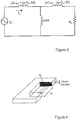
- the reluctance models finally translate to the inductance-based electrical model based on the duality principle as shown in Figure 3 .
- M L 2 M L lk 1 + M .
- Equation (1) 1 R m R lk 1 + 1 . 1 R m R lk 2 + 1
- the magnetic coupling coefficient of Equation (8) can be improved by reducing the ratios and Increasing the reluctance of the leakage flux path ( and ) can be achieved by either increasing the length of the leakage flux path l lk1 and l lk2 (the distance between the core limbs) or reducing the leakage cross-section areas A lk1 . and A lk2 (see Figure 4 ).
- the distance between the core limbs ( l lk1 and l lk2 ) is kept the same.
- a lk1 and A lk2 by reducing the length of the cores limbs as illustrated in the embodiments of Figures 5 and 6 ).
- the size of the air gap increases which results in greater reluctances and accordingly reduced mutual inductance.
- the mutual inductance is then improved by filling the available provided space (due to the shortened core limbs) with a greater number of turns.
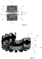
- Figure 5 shows an exemplary configuration of an inductive power transfer coil utilizing the topology of the present invention.
- a first magnetically permeable U core is formed by a base 1 and two limbs 2 and 3 extending from the base 1. Whilst transitions between the base and limbs are shown as angular transitions it will be appreciated that curved transitions may provide improved flux flow. Windings 4 are provided between and above the limbs 2 and 3 of the first U core.
- a second U core is formed by a base 5 and two limbs 6 and 7 extending from the base 5. Windings 8 are provide between and above the limbs 6 and 7 of the second U core.
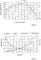
- Figure 6 shows an exemplary slip ring embodiment utilising the topology of Figure 5
- the coil arrangement includes a first coil assembly 9 that is relatively rotatable with respect to a second coil assembly 10, as per a slip ring arrangement.
- the first coil assembly 9 includes a plurality of magnetically permeable cores 11 (only one of which is indicated) arranged along an annular path.
- a first coil 12 is wound following the annular path between and above the limbs of each core 11.
- the second coil assembly 10 includes a plurality of magnetically permeable cores 13 (only one of which is indicated) arranged along an annular path.
- a second coil 14 is wound following the annular path between and above the limbs of each core 13.
- the plurality of cores 11 and 13 could each be replaced by a single core of annular form, although this form may be more expensive to produce. It will also be appreciated that this arrangement may also be implemented in linear form - either with a plurality of cores 11 and 13 in parallel linear arrangements or utilizing single opposed elongate cores. Further, it will be appreciated that rather than having the coil assemblies axially spaced they may be concentrically arranged with the limbs being generally radially directed. Whilst two limbs are shown in this embodiment it will be appreciated that three or more limbs may be used in other applications. It will be appreciated that the design may be implemented with or without a through hole.
- 3D-FEM models were used to compare coil assemblies utilizing cores with limbs ranging in length from a core with no limbs (0%) and a core with full length of limbs (100%) are considered.
- the percentages here representing the ratio of the height of the limb above the base to the height of the limb and winding above the base.
- the results shown in Figure 7 show that the magnetic coupling coefficient changes non-linearly versus with the length of the core limbs.
- the maximum magnetic coupling coefficient of about 0.653 is achieved when the length of the limbs reduced to about 50%. This compares to a value of about 0.58 for a conventional design in which the windings do not extend above the limbs.
- the magnetic coupling coefficient may be improved by about 13% without increasing the size of the coil assemblies.
- any value less than about 90% is advantageous with values below about 70% being more advantageous.
- Ratios between about 20% and about 70% are seen to be particularly advantageous with values between about 40% and about 60% being most advantageous with a maximum at about 50%.
- Figure 8 shows the variation in coupling coefficient for an air gap ranging from about 0.5 mm to about 50 mm. It can be seen in Figure 8 that for small air gaps ( ⁇ about 3.5 mm) the magnetic coupling coefficient of a conventional ("typical") design is greater than the coupling coefficient of the present embodiment ("proposed" design, in which the ratio of the height of the limb above the base to the height of the limb and winding above the base is about 50), as most of the flux lines tend to link the other side. As the air gap increases (> about 3.5 mm), the coupling coefficient of the present embodiment increases and remains greater than that of the "typical" design for larger air gaps.
- the invention may find application in wide range of inductive power transfer applications including slip rings, stationary wireless charging system for applications such as electric vehicles, linear arrangements such as are used for electric vehicles on roadways and automation, biomedical applications, connectors and couplings etc.
Landscapes
- Engineering & Computer Science (AREA)
- Power Engineering (AREA)
- Computer Networks & Wireless Communication (AREA)
- Chemical & Material Sciences (AREA)
- Composite Materials (AREA)
- Physics & Mathematics (AREA)
- Electromagnetism (AREA)
- Current-Collector Devices For Electrically Propelled Vehicles (AREA)
- Magnetic Treatment Devices (AREA)
Claims (15)
- Un bloc de bobine de transfert d'énergie inductive, comprenant :i. un noyau magnétiquement perméable comprenant une base (1) et une paire de branches espacées (2, 3) s'étendant à partir de la base, chaque branche ayant une face d'extrémité distale dans la direction de son extension, la base (1) et la paire de branches espacées (2, 3) formant un noyau en U ; etii. un enroulement (4) situé entre les branches (2, 3), caractérisé en ce que l'enroulement (4) est également situé au-dessus desdites faces d'extrémité distale de la paire de branches espacées (2, 3).
- Un bloc de bobine de transfert d'énergie inductive tel que revendiqué dans la revendication 1, dans lequel le rapport entre la hauteur des branches (2, 3) au-dessus de la base (1) et la hauteur des branches (2, 3) et de l'enroulement (4) au-dessus de la base est choisi dans le groupe constitué par :moins de 90 % ;moins de 70 % ;entre 20 % et 70 % ;entre 40 % et 60 % ; et50 %.
- Un bloc de bobine de transfert d'énergie inductive tel que revendiqué dans l'une des revendications précédentes, comprenant :une pluralité desdites noyaux agencés le long d'un trajet annulaire, ouun unique dit noyau annulaire situé le long d'un trajet annulaire,dans lequel l'enroulement suit le trajet annulaire entre les branches (2, 3) du noyau ou de chaque noyau.
- Un bloc de bobine de transfert d'énergie inductive tel que revendiqué dans la revendication 3, avec un trou traversant au centre du trajet annulaire.
- Un bloc de bobine de transfert d'énergie inductive tel que revendiqué dans la revendication 1, comprenant :un ou plusieurs desdits noyaux disposés le long d'un trajet linéaire,une pluralité desdits noyaux disposés le long d'un trajet linéaire ; ouun unique dit noyau linéaire situé le long d'un trajet linéaire.
- Un bloc de bobine de transfert d'énergie inductive tel que revendiqué dans l'une des revendications 3 à 5, dans lequel l'enroulement est situé entre et au-dessus de chaque noyau.
- Un bloc de bobine de transfert d'énergie inductive tel que revendiqué dans l'une des revendications précédentes, dans lequel chaque noyau possède trois branches (2, 3) ou plus s'étendant à partir de la base.
- Un bloc de bobine de transfert d'énergie inductive tel que revendiqué dans l'une des revendications précédentes, dans lequel la transition de la base (1) à chaque branche (2, 3) est courbe.
- Un agencement de bloc de bobine de transfert d'énergie inductive comprenant :i. un premier bloc de bobine (9) tel que revendiqué dans l'une des revendications précédentes ; etii. un second bloc de bobine (10) possédant un noyau magnétiquement perméable comprenant une base (5) et une paire de branches espacées (6, 7) s'étendant à partir de la base, le second bloc de bobine étant agencé par rapport au premier bloc de bobine (9) de telle manière qu'il y ait un couplage magnétique efficace entre les noyaux magnétiquement perméables (11) du premier et du second bloc de bobine (9, 10).
- Un agencement de bloc de bobine de transfert d'énergie inductive tel que revendiqué dans la revendication 9, dans lequel le premier et le second bloc de bobine (9, 10) sont agencés en relation de mobilité relative.
- Un agencement de bloc de bobine de transfert d'énergie inductive tel que revendiqué dans la revendication 9 ou la revendication 10, dans lequel un entrefer d'air supérieur à 3,5 mm existe entre le premier et le second bloc de bobine (9, 10).
- Un agencement de bloc de bobine de transfert d'énergie inductive tel que revendiqué dans la revendication 9 ou la revendication 10, dans lequel il existe entre le premier et le second bloc de bobine (9, 10) un entrefer d'air supérieur à la distance entre les branches (2, 3) du premier bloc de bobine (9) et entre les branches (6, 7) du second bloc de bobine (10).
- Un agencement de bloc de bobine de transfert d'énergie inductive tel que revendiqué dans l'une des revendications 10 à 12, dans lequel :
chacun du premier et du second bloc de bobine (9, 10) comprend :soit une pluralité desdits noyaux (11, 13) agencés le long d'un trajet annulaire ;soit un unique dit noyau annulaire (11, 13) disposé le long d'un trajet annulaire,dans lequel l'enroulement de chaque bloc de bobine suit le trajet annulaire entre les branches (2, 3) du noyau ou de chaque noyau (11, 13). - Un agencement de bloc de bobine de transfert d'énergie inductive tel que revendiqué dans la revendication 13, dans lequel les branches (2, 3) du premier et du second bloc de bobine (9, 10) sont globalement dirigées radialement par rapport au trajet annulaire.
- Un agencement de bloc de bobine de transfert d'énergie inductive tel que revendiqué dans la revendication 13, dans lequel les branches (2, 3) du premier et du second bloc de bobine (9, 10) sont globalement dirigées axialement par rapport au trajet annulaire.
Applications Claiming Priority (2)
| Application Number | Priority Date | Filing Date | Title |
|---|---|---|---|
| US201462000237P | 2014-05-19 | 2014-05-19 | |
| PCT/NZ2015/050056 WO2015178781A1 (fr) | 2014-05-19 | 2015-05-14 | Noyau magnétiquement perméable et agencement de bobine de transfert de puissance inductive |
Publications (3)
| Publication Number | Publication Date |
|---|---|
| EP3146541A1 EP3146541A1 (fr) | 2017-03-29 |
| EP3146541A4 EP3146541A4 (fr) | 2017-06-14 |
| EP3146541B1 true EP3146541B1 (fr) | 2020-06-03 |
Family
ID=54554339
Family Applications (1)
| Application Number | Title | Priority Date | Filing Date |
|---|---|---|---|
| EP15796688.8A Active EP3146541B1 (fr) | 2014-05-19 | 2015-05-14 | Noyau magnétiquement perméable et agencement de bobine de transfert de puissance inductive |
Country Status (3)
| Country | Link |
|---|---|
| US (1) | US10325719B2 (fr) |
| EP (1) | EP3146541B1 (fr) |
| WO (1) | WO2015178781A1 (fr) |
Families Citing this family (2)
| Publication number | Priority date | Publication date | Assignee | Title |
|---|---|---|---|---|
| CN106158956B (zh) * | 2015-04-08 | 2020-02-11 | 无锡华润上华科技有限公司 | 具有resurf结构的ldmosfet及其制造方法 |
| US10333293B2 (en) * | 2016-12-20 | 2019-06-25 | Witricity Corporation | Method for increasing pad efficiency and robustness |
Family Cites Families (37)
| Publication number | Priority date | Publication date | Assignee | Title |
|---|---|---|---|---|
| BE385703A (fr) * | 1932-01-15 | 1900-01-01 | ||
| US5000178A (en) | 1986-05-23 | 1991-03-19 | Lti Biomedical, Inc. | Shielded electromagnetic transducer |
| JPH03133110A (ja) * | 1989-10-19 | 1991-06-06 | Mitsubishi Electric Corp | 電磁結合接続器 |
| JP3247186B2 (ja) | 1993-03-29 | 2002-01-15 | 江藤電気株式会社 | 可動体側電動駆動手段への給電装置 |
| US5608771A (en) * | 1995-10-23 | 1997-03-04 | General Electric Company | Contactless power transfer system for a rotational load |
| US6151231A (en) | 1998-12-31 | 2000-11-21 | Motorola, Inc. | Circuit and method for reactive energy recirculation control in a series-resonant converter |
| US6320772B1 (en) | 1999-05-26 | 2001-11-20 | Matsushita Electric Industrial Co., Ltd. | Converter circuit having control means with capability to short-circuit converter output |
| JP4127935B2 (ja) | 1999-07-29 | 2008-07-30 | 大日本印刷株式会社 | 信号及び電源伝送装置並びにロータリージョイント |
| JP4681742B2 (ja) | 2001-02-14 | 2011-05-11 | Fdk株式会社 | 非接触カプラ |
| EP1547222B1 (fr) | 2002-06-10 | 2018-10-03 | City University of Hong Kong | Chargeur de batterie inductif plat |
| GB0320960D0 (en) | 2003-09-08 | 2003-10-08 | Splashpower Ltd | Improvements relating to improving flux patterns of inductive charging pads |
| US7233137B2 (en) | 2003-09-30 | 2007-06-19 | Sharp Kabushiki Kaisha | Power supply system |
| US7164591B2 (en) | 2003-10-01 | 2007-01-16 | International Rectifier Corporation | Bridge-less boost (BLB) power factor correction topology controlled with one cycle control |
| JP4096873B2 (ja) | 2003-12-05 | 2008-06-04 | 株式会社ダイフク | 無接触給電設備の誘導受電回路 |
| JP4852829B2 (ja) | 2004-07-28 | 2012-01-11 | セイコーエプソン株式会社 | 非接触電力伝送装置 |
| JP4608282B2 (ja) | 2004-10-28 | 2011-01-12 | 大日本印刷株式会社 | 非接触給電方法及び装置 |
| NZ539770A (en) * | 2005-04-29 | 2007-10-26 | Auckland Uniservices Ltd | Inductively coupled power transfer system |
| US7197113B1 (en) * | 2005-12-01 | 2007-03-27 | General Electric Company | Contactless power transfer system |
| JP5005703B2 (ja) * | 2005-12-02 | 2012-08-22 | コーニンクレッカ フィリップス エレクトロニクス エヌ ヴィ | 結合システム |
| US8169185B2 (en) | 2006-01-31 | 2012-05-01 | Mojo Mobility, Inc. | System and method for inductive charging of portable devices |
| NZ546955A (en) | 2006-05-02 | 2008-09-26 | Auckland Uniservices Ltd | Pick-up apparatus for inductive power transfer systems |
| JP2010530613A (ja) | 2007-05-10 | 2010-09-09 | オークランド ユニサービシズ リミテッド | 複数の電源を利用する電動車両 |
| WO2008140333A2 (fr) | 2007-05-10 | 2008-11-20 | Auckland Uniservices Limited | Véhicule électrique à multiples sources d'énergie |
| WO2009004587A1 (fr) | 2007-07-02 | 2009-01-08 | Alan Simon Levy | Protection de joueur de cartes |
| KR101948276B1 (ko) | 2009-02-05 | 2019-02-14 | 오클랜드 유니서비시즈 리미티드 | 유도 전력 전송 장치 |
| KR100944113B1 (ko) | 2009-02-27 | 2010-02-24 | 한국과학기술원 | 전기자동차용 전원공급 시스템 및 방법 |
| CA2757623A1 (fr) | 2009-04-08 | 2010-10-14 | Access Business Group International Llc | Reseau de bobines a selectionner |
| EP2462679B1 (fr) | 2009-08-07 | 2022-09-28 | Auckland UniServices Limited | Système de transfert de puissance inductive |
| JP5691458B2 (ja) | 2010-03-31 | 2015-04-01 | 日産自動車株式会社 | 非接触給電装置及び非接触給電方法 |
| KR101192370B1 (ko) | 2010-07-23 | 2012-10-17 | 유한회사 한림포스텍 | 무선 전력 통신 시스템, 그리고 그에 사용되는 무선 전력 공급기 및 수신기 |
| US8823318B2 (en) | 2011-07-25 | 2014-09-02 | ConvenientPower HK Ltd. | System and method for operating a mobile device |
| CN103947072A (zh) | 2011-09-07 | 2014-07-23 | 奥克兰联合服务有限公司 | 用于感应功率传输的磁场成形 |
| US9118203B2 (en) | 2011-11-15 | 2015-08-25 | Qualcomm Incorporated | Systems and methods for induction charging with a closed magnetic loop |
| CN104380567A (zh) | 2012-02-16 | 2015-02-25 | 奥克兰联合服务有限公司 | 多线圈通量衬垫 |
| US9236757B2 (en) | 2012-09-28 | 2016-01-12 | Broadcom Corporation | Wireless power transfer adaptation triggers |
| TW201415749A (zh) | 2012-10-12 | 2014-04-16 | Espower Electronics Inc | 多機型無線電源供應系統 |
| CN104798315B (zh) | 2012-11-29 | 2017-06-20 | 皇家飞利浦有限公司 | 无线感应式电力传输 |
-
2015
- 2015-05-14 EP EP15796688.8A patent/EP3146541B1/fr active Active
- 2015-05-14 WO PCT/NZ2015/050056 patent/WO2015178781A1/fr not_active Ceased
- 2015-05-14 US US15/312,398 patent/US10325719B2/en active Active
Non-Patent Citations (1)
| Title |
|---|
| None * |
Also Published As
| Publication number | Publication date |
|---|---|
| EP3146541A4 (fr) | 2017-06-14 |
| WO2015178781A1 (fr) | 2015-11-26 |
| US20170092419A1 (en) | 2017-03-30 |
| EP3146541A1 (fr) | 2017-03-29 |
| US10325719B2 (en) | 2019-06-18 |
Similar Documents
| Publication | Publication Date | Title |
|---|---|---|
| US11837877B2 (en) | Coil module, wireless charging transmitting apparatus, receiving apparatus, system, and terminal | |
| US9490063B2 (en) | Shielded power coupling device | |
| EP2916332B1 (fr) | Dispositif de couplage de puissance blindé | |
| EP2835805B1 (fr) | Bobine pour une inductance toroïdale à entrefer(s) | |
| EP2859562A2 (fr) | Tore doté d'une certaine perméabilité magnétique, et destiné à être employé dans des systèmes de transfert de puissance sans fil | |
| CN101527493A (zh) | 一种动磁式圆筒直线电机 | |
| CN104487337B (zh) | 带有自由链接磁通的三相旋转变压器 | |
| EP3146541B1 (fr) | Noyau magnétiquement perméable et agencement de bobine de transfert de puissance inductive | |
| KR101229631B1 (ko) | 표류 부하손을 절감하는 자기차폐형 변압기 | |
| US11908616B2 (en) | Coil unit for inductively charging a vehicle | |
| CN102136365A (zh) | 三根并联导线单列螺旋式线圈换位方法 | |
| US12358384B2 (en) | Ferrite wings systems and methods for inductive wireless power transfer | |
| US10153085B2 (en) | Low stray-loss transformers and methods of assembling the same | |
| US20160148751A1 (en) | Magnetic component and power transfer device | |
| US10269486B2 (en) | Magnetically permeable core and inductive power transfer coil arrangement | |
| CN114050663B (zh) | 井下旋转导向的能量信号同步传输耦合机构设计方法 | |
| US10840004B2 (en) | Reducing reluctance in magnetic devices | |
| CN202513025U (zh) | 一种带环形屏蔽盒的超高压电流互感器 | |
| EP2682959A2 (fr) | Structures magnétiques pour grand entrefer | |
| Youssef et al. | Performance evaluation of the wireless energy transmission system of the combined DD-Circular charging pad for electric vehicles | |
| RU2619087C2 (ru) | Протяженный по оси цилиндра кольцевой ферромагнитный сердечник высокочастотного трансформатора | |
| JP2013038334A (ja) | 超電導限流器 | |
| EP3349225A1 (fr) | Noyau pour un réacteur shunt électrique | |
| UA120831U (uk) | Електромагнітна система з регулюванням підмагнічування магнітопроводу | |
| CN109274184A (zh) | 旋转电机的定子 |
Legal Events
| Date | Code | Title | Description |
|---|---|---|---|
| STAA | Information on the status of an ep patent application or granted ep patent |
Free format text: STATUS: THE INTERNATIONAL PUBLICATION HAS BEEN MADE |
|
| PUAI | Public reference made under article 153(3) epc to a published international application that has entered the european phase |
Free format text: ORIGINAL CODE: 0009012 |
|
| STAA | Information on the status of an ep patent application or granted ep patent |
Free format text: STATUS: REQUEST FOR EXAMINATION WAS MADE |
|
| 17P | Request for examination filed |
Effective date: 20161209 |
|
| AK | Designated contracting states |
Kind code of ref document: A1 Designated state(s): AL AT BE BG CH CY CZ DE DK EE ES FI FR GB GR HR HU IE IS IT LI LT LU LV MC MK MT NL NO PL PT RO RS SE SI SK SM TR |
|
| AX | Request for extension of the european patent |
Extension state: BA ME |
|
| A4 | Supplementary search report drawn up and despatched |
Effective date: 20170511 |
|
| RIC1 | Information provided on ipc code assigned before grant |
Ipc: H01F 38/18 20060101ALI20170505BHEP Ipc: H02J 5/00 20160101ALI20170505BHEP Ipc: H02J 7/02 20160101ALI20170505BHEP Ipc: H01F 3/10 20060101ALI20170505BHEP Ipc: H01F 38/14 20060101AFI20170505BHEP |
|
| DAV | Request for validation of the european patent (deleted) | ||
| DAX | Request for extension of the european patent (deleted) | ||
| RAP1 | Party data changed (applicant data changed or rights of an application transferred) |
Owner name: POWERBYPROXI |
|
| RAP1 | Party data changed (applicant data changed or rights of an application transferred) |
Owner name: APPLE INC. |
|
| RIN1 | Information on inventor provided before grant (corrected) |
Inventor name: HU, AIGUO Inventor name: ABDOLKHANI, ALI |
|
| RAP1 | Party data changed (applicant data changed or rights of an application transferred) |
Owner name: APPLE INC. |
|
| RIN1 | Information on inventor provided before grant (corrected) |
Inventor name: HU, AIGUO Inventor name: ABDOLKHANI, ALI |
|
| GRAP | Despatch of communication of intention to grant a patent |
Free format text: ORIGINAL CODE: EPIDOSNIGR1 |
|
| STAA | Information on the status of an ep patent application or granted ep patent |
Free format text: STATUS: GRANT OF PATENT IS INTENDED |
|
| INTG | Intention to grant announced |
Effective date: 20191218 |
|
| RIN1 | Information on inventor provided before grant (corrected) |
Inventor name: ABDOLKHANI, ALI Inventor name: HU, AIGUO |
|
| GRAS | Grant fee paid |
Free format text: ORIGINAL CODE: EPIDOSNIGR3 |
|
| GRAA | (expected) grant |
Free format text: ORIGINAL CODE: 0009210 |
|
| STAA | Information on the status of an ep patent application or granted ep patent |
Free format text: STATUS: THE PATENT HAS BEEN GRANTED |
|
| AK | Designated contracting states |
Kind code of ref document: B1 Designated state(s): AL AT BE BG CH CY CZ DE DK EE ES FI FR GB GR HR HU IE IS IT LI LT LU LV MC MK MT NL NO PL PT RO RS SE SI SK SM TR |
|
| REG | Reference to a national code |
Ref country code: GB Ref legal event code: FG4D |
|
| REG | Reference to a national code |
Ref country code: CH Ref legal event code: EP Ref country code: AT Ref legal event code: REF Ref document number: 1277880 Country of ref document: AT Kind code of ref document: T Effective date: 20200615 |
|
| REG | Reference to a national code |
Ref country code: DE Ref legal event code: R096 Ref document number: 602015053839 Country of ref document: DE |
|
| REG | Reference to a national code |
Ref country code: LT Ref legal event code: MG4D |
|
| PG25 | Lapsed in a contracting state [announced via postgrant information from national office to epo] |
Ref country code: GR Free format text: LAPSE BECAUSE OF FAILURE TO SUBMIT A TRANSLATION OF THE DESCRIPTION OR TO PAY THE FEE WITHIN THE PRESCRIBED TIME-LIMIT Effective date: 20200904 Ref country code: NO Free format text: LAPSE BECAUSE OF FAILURE TO SUBMIT A TRANSLATION OF THE DESCRIPTION OR TO PAY THE FEE WITHIN THE PRESCRIBED TIME-LIMIT Effective date: 20200903 Ref country code: SE Free format text: LAPSE BECAUSE OF FAILURE TO SUBMIT A TRANSLATION OF THE DESCRIPTION OR TO PAY THE FEE WITHIN THE PRESCRIBED TIME-LIMIT Effective date: 20200603 Ref country code: FI Free format text: LAPSE BECAUSE OF FAILURE TO SUBMIT A TRANSLATION OF THE DESCRIPTION OR TO PAY THE FEE WITHIN THE PRESCRIBED TIME-LIMIT Effective date: 20200603 Ref country code: LT Free format text: LAPSE BECAUSE OF FAILURE TO SUBMIT A TRANSLATION OF THE DESCRIPTION OR TO PAY THE FEE WITHIN THE PRESCRIBED TIME-LIMIT Effective date: 20200603 |
|
| REG | Reference to a national code |
Ref country code: NL Ref legal event code: MP Effective date: 20200603 |
|
| PG25 | Lapsed in a contracting state [announced via postgrant information from national office to epo] |
Ref country code: HR Free format text: LAPSE BECAUSE OF FAILURE TO SUBMIT A TRANSLATION OF THE DESCRIPTION OR TO PAY THE FEE WITHIN THE PRESCRIBED TIME-LIMIT Effective date: 20200603 Ref country code: LV Free format text: LAPSE BECAUSE OF FAILURE TO SUBMIT A TRANSLATION OF THE DESCRIPTION OR TO PAY THE FEE WITHIN THE PRESCRIBED TIME-LIMIT Effective date: 20200603 Ref country code: BG Free format text: LAPSE BECAUSE OF FAILURE TO SUBMIT A TRANSLATION OF THE DESCRIPTION OR TO PAY THE FEE WITHIN THE PRESCRIBED TIME-LIMIT Effective date: 20200903 Ref country code: RS Free format text: LAPSE BECAUSE OF FAILURE TO SUBMIT A TRANSLATION OF THE DESCRIPTION OR TO PAY THE FEE WITHIN THE PRESCRIBED TIME-LIMIT Effective date: 20200603 |
|
| REG | Reference to a national code |
Ref country code: AT Ref legal event code: MK05 Ref document number: 1277880 Country of ref document: AT Kind code of ref document: T Effective date: 20200603 |
|
| PG25 | Lapsed in a contracting state [announced via postgrant information from national office to epo] |
Ref country code: NL Free format text: LAPSE BECAUSE OF FAILURE TO SUBMIT A TRANSLATION OF THE DESCRIPTION OR TO PAY THE FEE WITHIN THE PRESCRIBED TIME-LIMIT Effective date: 20200603 Ref country code: AL Free format text: LAPSE BECAUSE OF FAILURE TO SUBMIT A TRANSLATION OF THE DESCRIPTION OR TO PAY THE FEE WITHIN THE PRESCRIBED TIME-LIMIT Effective date: 20200603 |
|
| PG25 | Lapsed in a contracting state [announced via postgrant information from national office to epo] |
Ref country code: ES Free format text: LAPSE BECAUSE OF FAILURE TO SUBMIT A TRANSLATION OF THE DESCRIPTION OR TO PAY THE FEE WITHIN THE PRESCRIBED TIME-LIMIT Effective date: 20200603 Ref country code: CZ Free format text: LAPSE BECAUSE OF FAILURE TO SUBMIT A TRANSLATION OF THE DESCRIPTION OR TO PAY THE FEE WITHIN THE PRESCRIBED TIME-LIMIT Effective date: 20200603 Ref country code: PT Free format text: LAPSE BECAUSE OF FAILURE TO SUBMIT A TRANSLATION OF THE DESCRIPTION OR TO PAY THE FEE WITHIN THE PRESCRIBED TIME-LIMIT Effective date: 20201006 Ref country code: AT Free format text: LAPSE BECAUSE OF FAILURE TO SUBMIT A TRANSLATION OF THE DESCRIPTION OR TO PAY THE FEE WITHIN THE PRESCRIBED TIME-LIMIT Effective date: 20200603 Ref country code: EE Free format text: LAPSE BECAUSE OF FAILURE TO SUBMIT A TRANSLATION OF THE DESCRIPTION OR TO PAY THE FEE WITHIN THE PRESCRIBED TIME-LIMIT Effective date: 20200603 Ref country code: IT Free format text: LAPSE BECAUSE OF FAILURE TO SUBMIT A TRANSLATION OF THE DESCRIPTION OR TO PAY THE FEE WITHIN THE PRESCRIBED TIME-LIMIT Effective date: 20200603 Ref country code: SM Free format text: LAPSE BECAUSE OF FAILURE TO SUBMIT A TRANSLATION OF THE DESCRIPTION OR TO PAY THE FEE WITHIN THE PRESCRIBED TIME-LIMIT Effective date: 20200603 Ref country code: RO Free format text: LAPSE BECAUSE OF FAILURE TO SUBMIT A TRANSLATION OF THE DESCRIPTION OR TO PAY THE FEE WITHIN THE PRESCRIBED TIME-LIMIT Effective date: 20200603 |
|
| PG25 | Lapsed in a contracting state [announced via postgrant information from national office to epo] |
Ref country code: SK Free format text: LAPSE BECAUSE OF FAILURE TO SUBMIT A TRANSLATION OF THE DESCRIPTION OR TO PAY THE FEE WITHIN THE PRESCRIBED TIME-LIMIT Effective date: 20200603 Ref country code: PL Free format text: LAPSE BECAUSE OF FAILURE TO SUBMIT A TRANSLATION OF THE DESCRIPTION OR TO PAY THE FEE WITHIN THE PRESCRIBED TIME-LIMIT Effective date: 20200603 Ref country code: IS Free format text: LAPSE BECAUSE OF FAILURE TO SUBMIT A TRANSLATION OF THE DESCRIPTION OR TO PAY THE FEE WITHIN THE PRESCRIBED TIME-LIMIT Effective date: 20201003 |
|
| REG | Reference to a national code |
Ref country code: DE Ref legal event code: R097 Ref document number: 602015053839 Country of ref document: DE |
|
| PLBE | No opposition filed within time limit |
Free format text: ORIGINAL CODE: 0009261 |
|
| STAA | Information on the status of an ep patent application or granted ep patent |
Free format text: STATUS: NO OPPOSITION FILED WITHIN TIME LIMIT |
|
| PG25 | Lapsed in a contracting state [announced via postgrant information from national office to epo] |
Ref country code: DK Free format text: LAPSE BECAUSE OF FAILURE TO SUBMIT A TRANSLATION OF THE DESCRIPTION OR TO PAY THE FEE WITHIN THE PRESCRIBED TIME-LIMIT Effective date: 20200603 |
|
| 26N | No opposition filed |
Effective date: 20210304 |
|
| PG25 | Lapsed in a contracting state [announced via postgrant information from national office to epo] |
Ref country code: SI Free format text: LAPSE BECAUSE OF FAILURE TO SUBMIT A TRANSLATION OF THE DESCRIPTION OR TO PAY THE FEE WITHIN THE PRESCRIBED TIME-LIMIT Effective date: 20200603 |
|
| REG | Reference to a national code |
Ref country code: CH Ref legal event code: PL |
|
| PG25 | Lapsed in a contracting state [announced via postgrant information from national office to epo] |
Ref country code: LI Free format text: LAPSE BECAUSE OF NON-PAYMENT OF DUE FEES Effective date: 20210531 Ref country code: MC Free format text: LAPSE BECAUSE OF FAILURE TO SUBMIT A TRANSLATION OF THE DESCRIPTION OR TO PAY THE FEE WITHIN THE PRESCRIBED TIME-LIMIT Effective date: 20200603 Ref country code: LU Free format text: LAPSE BECAUSE OF NON-PAYMENT OF DUE FEES Effective date: 20210514 Ref country code: CH Free format text: LAPSE BECAUSE OF NON-PAYMENT OF DUE FEES Effective date: 20210531 |
|
| REG | Reference to a national code |
Ref country code: BE Ref legal event code: MM Effective date: 20210531 |
|
| PG25 | Lapsed in a contracting state [announced via postgrant information from national office to epo] |
Ref country code: IE Free format text: LAPSE BECAUSE OF NON-PAYMENT OF DUE FEES Effective date: 20210514 |
|
| PG25 | Lapsed in a contracting state [announced via postgrant information from national office to epo] |
Ref country code: FR Free format text: LAPSE BECAUSE OF NON-PAYMENT OF DUE FEES Effective date: 20210531 |
|
| PG25 | Lapsed in a contracting state [announced via postgrant information from national office to epo] |
Ref country code: BE Free format text: LAPSE BECAUSE OF NON-PAYMENT OF DUE FEES Effective date: 20210531 |
|
| PG25 | Lapsed in a contracting state [announced via postgrant information from national office to epo] |
Ref country code: HU Free format text: LAPSE BECAUSE OF FAILURE TO SUBMIT A TRANSLATION OF THE DESCRIPTION OR TO PAY THE FEE WITHIN THE PRESCRIBED TIME-LIMIT; INVALID AB INITIO Effective date: 20150514 |
|
| PG25 | Lapsed in a contracting state [announced via postgrant information from national office to epo] |
Ref country code: CY Free format text: LAPSE BECAUSE OF FAILURE TO SUBMIT A TRANSLATION OF THE DESCRIPTION OR TO PAY THE FEE WITHIN THE PRESCRIBED TIME-LIMIT Effective date: 20200603 |
|
| P01 | Opt-out of the competence of the unified patent court (upc) registered |
Effective date: 20230526 |
|
| PG25 | Lapsed in a contracting state [announced via postgrant information from national office to epo] |
Ref country code: MK Free format text: LAPSE BECAUSE OF FAILURE TO SUBMIT A TRANSLATION OF THE DESCRIPTION OR TO PAY THE FEE WITHIN THE PRESCRIBED TIME-LIMIT Effective date: 20200603 |
|
| PG25 | Lapsed in a contracting state [announced via postgrant information from national office to epo] |
Ref country code: MT Free format text: LAPSE BECAUSE OF FAILURE TO SUBMIT A TRANSLATION OF THE DESCRIPTION OR TO PAY THE FEE WITHIN THE PRESCRIBED TIME-LIMIT Effective date: 20200603 |
|
| PGFP | Annual fee paid to national office [announced via postgrant information from national office to epo] |
Ref country code: GB Payment date: 20250320 Year of fee payment: 11 |
|
| PGFP | Annual fee paid to national office [announced via postgrant information from national office to epo] |
Ref country code: DE Payment date: 20250319 Year of fee payment: 11 |
|
| PG25 | Lapsed in a contracting state [announced via postgrant information from national office to epo] |
Ref country code: TR Free format text: LAPSE BECAUSE OF FAILURE TO SUBMIT A TRANSLATION OF THE DESCRIPTION OR TO PAY THE FEE WITHIN THE PRESCRIBED TIME-LIMIT Effective date: 20200603 |