EP3146553B1 - Power relais for a vehicle - Google Patents
Power relais for a vehicle Download PDFInfo
- Publication number
- EP3146553B1 EP3146553B1 EP15728403.5A EP15728403A EP3146553B1 EP 3146553 B1 EP3146553 B1 EP 3146553B1 EP 15728403 A EP15728403 A EP 15728403A EP 3146553 B1 EP3146553 B1 EP 3146553B1
- Authority
- EP
- European Patent Office
- Prior art keywords
- power relay
- housing
- connection
- housing pot
- radial
- Prior art date
- Legal status (The legal status is an assumption and is not a legal conclusion. Google has not performed a legal analysis and makes no representation as to the accuracy of the status listed.)
- Active
Links
Images





Classifications
-
- H—ELECTRICITY
- H01—ELECTRIC ELEMENTS
- H01H—ELECTRIC SWITCHES; RELAYS; SELECTORS; EMERGENCY PROTECTIVE DEVICES
- H01H50/00—Details of electromagnetic relays
- H01H50/02—Bases; Casings; Covers
- H01H50/023—Details concerning sealing, e.g. sealing casing with resin
-
- H—ELECTRICITY
- H01—ELECTRIC ELEMENTS
- H01H—ELECTRIC SWITCHES; RELAYS; SELECTORS; EMERGENCY PROTECTIVE DEVICES
- H01H50/00—Details of electromagnetic relays
- H01H50/02—Bases; Casings; Covers
- H01H50/04—Mounting complete relay or separate parts of relay on a base or inside a case
- H01H50/047—Details concerning mounting a relays
-
- H—ELECTRICITY
- H01—ELECTRIC ELEMENTS
- H01H—ELECTRIC SWITCHES; RELAYS; SELECTORS; EMERGENCY PROTECTIVE DEVICES
- H01H1/00—Contacts
- H01H1/60—Auxiliary means structurally associated with the switch for cleaning or lubricating contact-making surfaces
-
- H—ELECTRICITY
- H01—ELECTRIC ELEMENTS
- H01H—ELECTRIC SWITCHES; RELAYS; SELECTORS; EMERGENCY PROTECTIVE DEVICES
- H01H47/00—Circuit arrangements not adapted to a particular application of the relay and designed to obtain desired operating characteristics or to provide energising current
- H01H47/22—Circuit arrangements not adapted to a particular application of the relay and designed to obtain desired operating characteristics or to provide energising current for supplying energising current for relay coil
-
- H—ELECTRICITY
- H01—ELECTRIC ELEMENTS
- H01H—ELECTRIC SWITCHES; RELAYS; SELECTORS; EMERGENCY PROTECTIVE DEVICES
- H01H50/00—Details of electromagnetic relays
- H01H50/02—Bases; Casings; Covers
- H01H50/04—Mounting complete relay or separate parts of relay on a base or inside a case
- H01H50/041—Details concerning assembly of relays
-
- H—ELECTRICITY
- H01—ELECTRIC ELEMENTS
- H01H—ELECTRIC SWITCHES; RELAYS; SELECTORS; EMERGENCY PROTECTIVE DEVICES
- H01H50/00—Details of electromagnetic relays
- H01H50/12—Ventilating; Cooling; Heating
-
- H—ELECTRICITY
- H01—ELECTRIC ELEMENTS
- H01H—ELECTRIC SWITCHES; RELAYS; SELECTORS; EMERGENCY PROTECTIVE DEVICES
- H01H50/00—Details of electromagnetic relays
- H01H50/16—Magnetic circuit arrangements
- H01H50/18—Movable parts of magnetic circuits, e.g. armature
- H01H50/20—Movable parts of magnetic circuits, e.g. armature movable inside coil and substantially lengthwise with respect to axis thereof; movable coaxially with respect to coil
-
- H—ELECTRICITY
- H01—ELECTRIC ELEMENTS
- H01H—ELECTRIC SWITCHES; RELAYS; SELECTORS; EMERGENCY PROTECTIVE DEVICES
- H01H50/00—Details of electromagnetic relays
- H01H50/16—Magnetic circuit arrangements
- H01H50/36—Stationary parts of magnetic circuit, e.g. yoke
-
- H—ELECTRICITY
- H01—ELECTRIC ELEMENTS
- H01H—ELECTRIC SWITCHES; RELAYS; SELECTORS; EMERGENCY PROTECTIVE DEVICES
- H01H9/00—Details of switching devices, not covered by groups H01H1/00 - H01H7/00
- H01H9/02—Bases, casings, or covers
- H01H9/04—Dustproof, splashproof, drip-proof, waterproof, or flameproof casings
- H01H9/042—Explosion-proof cases
- H01H9/043—Explosion-proof cases with pressure-relief devices
-
- H—ELECTRICITY
- H01—ELECTRIC ELEMENTS
- H01H—ELECTRIC SWITCHES; RELAYS; SELECTORS; EMERGENCY PROTECTIVE DEVICES
- H01H50/00—Details of electromagnetic relays
- H01H50/44—Magnetic coils or windings
- H01H2050/446—Details of the insulating support of the coil, e.g. spool, bobbin, former
-
- H—ELECTRICITY
- H01—ELECTRIC ELEMENTS
- H01H—ELECTRIC SWITCHES; RELAYS; SELECTORS; EMERGENCY PROTECTIVE DEVICES
- H01H2231/00—Applications
- H01H2231/026—Car
-
- H—ELECTRICITY
- H01—ELECTRIC ELEMENTS
- H01H—ELECTRIC SWITCHES; RELAYS; SELECTORS; EMERGENCY PROTECTIVE DEVICES
- H01H2235/00—Springs
- H01H2235/01—Spiral spring
-
- H—ELECTRICITY
- H01—ELECTRIC ELEMENTS
- H01H—ELECTRIC SWITCHES; RELAYS; SELECTORS; EMERGENCY PROTECTIVE DEVICES
- H01H47/00—Circuit arrangements not adapted to a particular application of the relay and designed to obtain desired operating characteristics or to provide energising current
- H01H47/001—Functional circuits, e.g. logic, sequencing, interlocking circuits
-
- H—ELECTRICITY
- H01—ELECTRIC ELEMENTS
- H01H—ELECTRIC SWITCHES; RELAYS; SELECTORS; EMERGENCY PROTECTIVE DEVICES
- H01H47/00—Circuit arrangements not adapted to a particular application of the relay and designed to obtain desired operating characteristics or to provide energising current
- H01H47/002—Monitoring or fail-safe circuits
-
- H—ELECTRICITY
- H01—ELECTRIC ELEMENTS
- H01H—ELECTRIC SWITCHES; RELAYS; SELECTORS; EMERGENCY PROTECTIVE DEVICES
- H01H47/00—Circuit arrangements not adapted to a particular application of the relay and designed to obtain desired operating characteristics or to provide energising current
- H01H47/22—Circuit arrangements not adapted to a particular application of the relay and designed to obtain desired operating characteristics or to provide energising current for supplying energising current for relay coil
- H01H47/226—Circuit arrangements not adapted to a particular application of the relay and designed to obtain desired operating characteristics or to provide energising current for supplying energising current for relay coil for bistable relays
-
- H—ELECTRICITY
- H01—ELECTRIC ELEMENTS
- H01H—ELECTRIC SWITCHES; RELAYS; SELECTORS; EMERGENCY PROTECTIVE DEVICES
- H01H50/00—Details of electromagnetic relays
- H01H50/02—Bases; Casings; Covers
- H01H50/021—Bases; Casings; Covers structurally combining a relay and an electronic component, e.g. varistor, RC circuit
-
- H—ELECTRICITY
- H01—ELECTRIC ELEMENTS
- H01H—ELECTRIC SWITCHES; RELAYS; SELECTORS; EMERGENCY PROTECTIVE DEVICES
- H01H50/00—Details of electromagnetic relays
- H01H50/14—Terminal arrangements
-
- H—ELECTRICITY
- H01—ELECTRIC ELEMENTS
- H01H—ELECTRIC SWITCHES; RELAYS; SELECTORS; EMERGENCY PROTECTIVE DEVICES
- H01H50/00—Details of electromagnetic relays
- H01H50/16—Magnetic circuit arrangements
- H01H50/18—Movable parts of magnetic circuits, e.g. armature
- H01H50/30—Mechanical arrangements for preventing or damping vibration or shock, e.g. by balancing of armature
-
- H—ELECTRICITY
- H01—ELECTRIC ELEMENTS
- H01H—ELECTRIC SWITCHES; RELAYS; SELECTORS; EMERGENCY PROTECTIVE DEVICES
- H01H50/00—Details of electromagnetic relays
- H01H50/54—Contact arrangements
- H01H50/546—Contact arrangements for contactors having bridging contacts
Definitions
- the invention relates to a power relay for a vehicle, in particular a commercial vehicle.
- Generic power relays are used in vehicle technology, especially in commercial vehicles.
- the power relays are here used on the one hand to electrically disconnect the vehicle battery from the electrical system.
- Such relays are used to switch electric motors of adjusting devices (e.g., hydraulic pump or lifting platform).
- Such a power relay must be able to switch currents up to a current of about 300 amperes at low voltage, typically 12 to 24 volts, and must be solidly built accordingly.
- Conventional relays used for this purpose typically consist of a cup-shaped body of metal (e.g., iron or steel) in which a magnetic coil, a magnetic yoke, and a magnet armature connected to a contact bridge (double contact) are housed.
- the power relay To connect the power relay to a load circuit to be switched in the vehicle, the power relay typically includes solid metal studs (threaded bolts) typically 0.5 to 1 cm in diameter. Cable lugs of the connection lines of the load circuit to be switched are fixed in a contacting manner by means of nuts (contact nuts) on these connection pins.
- Such power relays are in particular made JP 2006 019148 A .
- the conventional power relays are comparatively heavy and expensive to manufacture.
- Another problem of conventionally. used power relay is that currently a variety of different building variants are used, which are different distances of the CONFIRMATION COPY Connection bolts and different mounting options for the relay housing (eg laterally on the housing pot, on the connection side or on the opposite to this bottom of the relay housing) differ.
- the invention has for its object to provide a particularly rationally manufacturable and easy-to-build power relay for a vehicle, especially a commercial vehicle.
- the power relay comprises a housing which is formed from a connection socket and a housing pot mounted thereon. Two connection bolts are inserted in the connection socket, via which the power relay can be contacted with connecting cables of an external load circuit to be connected.
- the power relay further comprises a coil assembly arranged in the housing with a magnet coil and a corresponding magnet armature.
- the magnet armature is in this case coupled via a force transmission member with a contact bridge and under the action of a magnetic field generated by the magnetic field displaceable in the housing, that the contact bridge is reversibly movable between a closed position and an opening pitch.
- the closed position is in this case characterized in that the contact bridge bridges the connecting pins in an electrically conductive manner, as a result of which the power relay is switched on.
- the open position is characterized in that the contact bridge is de thumbiert of the terminal bolt, so that there is no conductive connection between the terminal bolt and the power relay is thus switched off.
- the housing pot is designed as a plastic injection-molded part. This allows for a significant reduction in manufacturing and material costs as well as significant weight savings as compared to conventional power relays provided with a metal can.
- the connection socket is also preferably a plastic injection-molded component.
- this can optionally be a bistable relay which permanently maintains both the closed position and the open position in the de-energized state of the magnet coil, or it can be a monostable relay.
- the power relay can be designed as normally open or normally closed, wherein the relay automatically assumes the open position when the solenoid coil is not energized, and the closed position in the latter design.
- both bistable and monostable designs of the power relay are realized according to the construction principle of the invention.
- the coil assembly further comprises a magnetic yoke.
- the yoke expediently comprises a torsionally stable structure which is rotatably received in this over the entire axial height of the housing pot.
- the axial height here is the extension of the housing pot along the housing top axis perpendicular to the bottom of the housing pot.
- the torsionally stable structure of the magnetic yoke is formed in an expedient embodiment by a one-piece, U-shaped angled bracket whose legs surround the magnetic coil parallel to its coil axis.
- the housing pot Due to the rotationally fixed receiving the magnetic yoke, the housing pot initiates a torque acting on it, which is caused for example by tightening the contact nuts, in the torsion stable running magnetic yoke.
- the yoke, in particular the bracket must always be twisted, which in turn relieves the housing pot.
- material fatigue or even breakage of the housing pot is counteracted.
- the terminal base is preferably also coupled to the magnetic yoke so as to be secure against rotation, for example by virtue of the magnet yoke engaging in form-fitting manner with corresponding projections in corresponding recesses of the terminal socket.
- torques exerted on the connection socket are not transferred to the magnetic yoke, but only indirectly via the housing pot. Rather, at least a portion of these torques is introduced directly from the terminal socket in the magnetic yoke, which in turn relieves the housing pot, and in particular the connection between the housing pot and the terminal socket.
- the power relay in the context of the invention can be a purely electromechanical component, in which the magnetic coil is activated (energized) solely on the basis of external control signals and deactivated (switched off).
- the power relay additionally comprises a control electronics accommodated in the housing for controlling the magnetic coil.
- the control electronics converts external control signals (which in this case can also be output, for example, as pulse signals, in particular in digital form) into a corresponding control current for the magnetic coil.
- control electronics further includes other functions, such as current or voltage measurement between the terminal pins and / or protection functions, a forced shutdown of the power relay in case of over- and / or undervoltage, overload or - in multi-pole versions of the power relay - a fault current or an asymmetrical current distribution effect.
- other functions such as current or voltage measurement between the terminal pins and / or protection functions, a forced shutdown of the power relay in case of over- and / or undervoltage, overload or - in multi-pole versions of the power relay - a fault current or an asymmetrical current distribution effect.
- the power relay comprises a number of signal terminals, each of which is in each case connectable to an external signal line.
- the signal connections are expediently, as well as the connection bolts for the load current, fixed in the connection socket.
- the signal terminals serve to supply at least one electrical control signal to the power relay and / or to output at least one electrical state signal by the power relay.
- at least one of the signal terminals for supplying an electrical supply voltage or an electrical reference potential, in particular ground, also provided.
- the signal connections are in this case contacted directly with the magnetic coil.
- the control electronics provides additional functions (for example, measuring functions, protective functions, bus communication, etc.).
- the signal supplied via the signal terminals are used in the latter case usually only indirectly to control the solenoid.
- the housing pot engages on the outside with a collar around the radial web of the connection socket, wherein the collar projects axially beyond the radial web.
- the collar of the housing pot thus surrounds the molded onto the terminal base radial bar in the manner of a balustrade.
- a trough-like receptacle (hereinafter referred to briefly as "tub") is formed by the collar and the connection socket for the potting compound. In the assembled state of the power relay, this tub is completely or at least partially filled with the potting compound.
- connection conductor which is preferably formed by a bent sheet metal stamped part
- connection conductors is in this case preferably passed through in the region of the tub through the connection socket.
- the collar of the housing pot is provided in the region of the tub with at least one radial contour.
- the or each radial contour of the collar can be formed by a radial recess (which reduces the material thickness of the collar) or a radial projection (which increases the material thickness of the collar).
- Corresponding to the or each radial contour at least one mating contour is formed on the connection socket in the region of the trough.
- the radial contour and the corresponding mating contour form a form-locking connection with the potting compound, by means of which the connection socket and the housing pot are locked together in the circumferential direction, ie tangentially to the axis of the magnet coil and of the housing pot.
- the radial contour and the corresponding mating contour continue to undercuts, due to which the housing pot and the connection socket by form-locking the potting compound with the radial contour and the mating contour in the radial Direction are locked together.
- the radial contour is designed as a latching nose, which engages over the radial web and thus latched to the housing pot.
- the cause of the high gas pressure may in this case consist in the warming-related expansion of the air in the housing interior and / or in the evaporation of residual moisture of the air taken up in the housing interior.
- the cause of the air heating can in turn be a switching arc or the heating of the current-carrying parts due to the current flow (in particular a short-circuit current).
- the explosion or the uncontrolled bursting of the housing can lead to dangerous situations, in particular a short circuit of live parts with mass and an associated risk of fire or personal injury, and must therefore be excluded.
- an overpressure protection is provided in an advantageous embodiment of the power relay in the housing - and this preferably in the housing pot - which releases a gas discharge opening in the case of a critical overpressure in the housing, and thus a controlled Ensures pressure equalization with the environment.
- the overpressure protection can be formed by a separately manufactured and inserted into the housing pot (or possibly in the connection socket) valve, in particular by a spring-loaded ball valve or a tearing in the overpressure membrane (optionally semi-permeable by nature, ie gas-permeable, but not liquid permeable can).
- the overpressure protection but in the housing (and in particular in the housing pot) integrally integrated, in particular to the housing molded.
- the overpressure protection is formed in particular by a predetermined breaking point, which bursts in the overpressure case and thus releases the gas ejection opening to relieve the remaining housing areas.
- the predetermined breaking point preferably has a curved, for example U-shaped, V-shaped, or trapezoidal, shape and thus surrounds from three sides a tab-like portion (hereinafter "flap") of the housing, which forms the closure of the overpressure protection.
- the fourth side of this tab is expediently designed as a film joint along a connecting line extending between the ends of the predetermined breaking point.
- the breaking point tab By the framed by the breaking point tab in this case a gas discharge opening is formed with a defined shape and size.
- the film joint connecting the predetermined breaking point allows the tab to be bent outwardly from the housing wall when the predetermined breaking point bursts open, but prevents the tab from tearing off in an uncontrolled manner, thereby counteracting possible personal injury or damage to adjacent parts.
- the predetermined breaking point in particular has a keyhole shape, that is to say it is of U-shaped design with a circularly prepared base.
- the power relay is provided in an expedient development with a safety function that generates a warning signal after the failure of the predetermined breaking point and / or the power relay forcibly switches to a safe state.
- the safety function comprises a forced shutdown, by means of which the power relay permanently shuts off - by decontacting the contact bridge from the terminal bolts - and is thus irreversibly shut down.
- the fuse function of the power relay - in adaptation to the particular application - but also include the switching of the power relay. For example, a power relay used as a battery switch in a commercial vehicle must remain switched on even in the event of a fault, since otherwise the electrical supply of the vehicle electrical system - if necessary while driving - would collapse.
- the forced shutdown detects the overpressure case independently of the state of the predetermined breaking point, for example by a separate overpressure sensor which is triggered in a critical overpressure case.
- the forced shutdown is triggered directly by the bursting of the predetermined breaking point.
- an electrical safety line is mechanically coupled to the predetermined breaking point such that the safety line is severed in the event of failure of the predetermined breaking point.
- the fuse line is here - directly or indirectly - in operative connection with the solenoid, so that their severance causes the forced shutdown of the power relay.
- the coil assembly is preferably designed as a self-stable (stable in itself) and contiguous structural unit.
- the coil assembly is thus designed such that it holds together without the surrounding parts of the housing. This makes it possible to assemble the coil assembly outside the housing, which in particular accommodates an automated manufacturing, and to use as a whole in the housing.
- Core element of the self-stable coil assembly is in an advantageous embodiment of the power relay a trained by a plastic injection molded part, one-piece support body on which the magnetic coil is wound directly.
- the carrier body comprises at least one pocket which serves to receive a pole shoe of the magnetic yoke and, if present, at least one permanent magnet. Permanent magnets are provided here in bistable designs of the power relay.
- the or each pocket preferably has a wall with a defined wall thickness between 0.2 mm and 0.5 mm, in particular at about 0.3 mm, by which the corresponding pole piece of the magnetic yoke is spaced from the guided inside the support body magnet armature ,
- a wall with a defined wall thickness between 0.2 mm and 0.5 mm, in particular at about 0.3 mm, by which the corresponding pole piece of the magnetic yoke is spaced from the guided inside the support body magnet armature ,
- the coil assembly is preferably attached to the terminal socket, wherein a snap connection is preferably used for this attachment. This makes it possible to mount all electrically and by mechanical movement cooperating parts of the power relay outside of the housing.
- a coupling rod is provided in an expedient embodiment of the power relay, which extends along a coil axis of the magnetic coil.
- the coupling rod is slidably mounted in a central part of the magnetic yoke.
- the contact bridge is attached to the coupling rod.
- the coupling rod is in this case, in an advantageous embodiment of the invention, slidably mounted on its armature-distant side (thus in the region of the contact bridge) in the connection base.
- the coupling rod dives in particular with a - in the connection base slidably mounted - bearing section through the contact bridge.
- control electronics present in this case are preferably arranged outside the magnetic yoke, and in this case in particular parallel to one of the side faces of the housing pot.
- the control electronics are shielded by the heat generated by the energization of the magnetic coil.
- the control electronics is thus arranged in the cold area of the power relay, whereby the control electronics is spared.
- the housing pot preferably carries both on a side surface and at its bottom each have a mounting surface which is provided with screw holes for receiving fastening screws.
- the power relay can either be mounted directly or - to adapt to different hole distances of the installation environment - via adapter plates by screwing.
- the respectively provided in the mounting surfaces of the housing pot screw openings are preferably realized by threaded sleeves made of metal, which are pressed into openings of the plastic material of the housing pot or encapsulated with the material of the housing pot.
- control electronics are preferably connected to the terminal bolts.
- the control electronics are set up to pick up the electrical voltage dropping between the connecting bolts and to detect them by measurement.
- a supply voltage for the control electronics is preferably tapped off via the connection bolts.
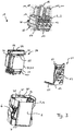
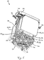
- Power relay 1 shown as a whole comprises a housing 2, which is formed from two parts, namely a terminal socket 3 and a housing pot 4. Both the terminal base 3 and the housing pot 4 are in this case formed as injection-molded plastic parts.
- the terminal base 3 limits the housing 2 to a connection side, at which the power relay 1 can be contacted with an external load circuit and with external control lines.
- This connection side is hereinafter - regardless of the actual orientation of the power relay 1 in the enclosed space - also referred to as the top 5.
- the housing pot 4 encloses with four side walls 6 and a housing bottom 7, the remaining sides of an approximately cuboid housing interior 8 (FIGS. Fig. 12 to 14 ).
- the housing bottom 7 in this case closes off the housing 2 from an underside 9 facing away from the upper side 5 (wherein the term "lower side" is also used independently of the actual orientation of the power relay 1 in the enclosed space).
- connection bolts 10 For connecting two connecting lines of the load circuit to be connected, three solid connecting bolts 10 are fixed in the connecting base 3, each protruding out of the housing 2 with a threaded shaft 11 to the outside.
- the connecting bolt 10 are solid turned parts made of metal which, for example, have a diameter of 0.8 cm in the region of the threaded shaft 11.
- an end-side cable lug of this connection line is placed on the associated threaded shaft 11 and screw-contacted by means of a nut (contact nut).
- the connection bolts 10 may also be formed by sleeves, each with a threaded bore. Instead of contact nuts contact screws for contacting the leads are provided in this case, which are screwed into the threaded holes.
- the connection bolts 10 are fixed in the connection socket 3 by extrusion coating with the plastic material of the connection socket 11.
- a partition wall 12 is formed on the outside of the terminal base 3, which projects into the intermediate space formed between the terminal pin 10.
- the terminal base 3 To control the power relay 1, that is to trigger switching processes by which the power relay 1 - by making an in-house electrically conductive connection between the terminal bolt 10 - turned on or - by disconnecting this electrically conductive connection - is turned off, are on the terminal base 3 further a plurality of (three exemplary here) signal terminals 13 are formed, via the three corresponding external control lines can each be schraubheftiert with an end-side cable lug with the power relay 1.
- Each signal terminal 13 is electrically connected to the housing interior 8 via a connecting conductor 14 in the form of a bent stamped sheet metal part.
- the connection conductors 14 are in this case inserted between the terminal base 3 and the housing pot 4 or also by Encapsulation held in the connection socket 3.
- the signal connections 13 are protected against contact by a separate, snap-on plastic cover 15.
- Fig. 3 shows the power relay 1 in partially dismounted state. It can be seen from this representation that the power relay 1 is formed from four subassemblies which are in each case connected in one another. In addition to the housing parts already described, namely the terminal base 3 with the attached connecting pins 10 and signal terminals 13 and next to the housing pot 4, the power relay 1 accordingly comprises a coil assembly 20 and a hereinafter referred to as board 21 line carrier.
- the power relay 1 is a bistable relay.
- the pole shoes 28 and the leg ends of the bracket 27 are each two platelet-shaped permanent magnets 29 interposed.
- one or two of the permanent magnets 29 assigned to a pole shoe 28 may also be replaced by ferromagnetic plates of the same size.
- the permanent magnets 29 are completely replaced by ferromagnetic material.
- the coil assembly 20 comprises a magnetic coil 30 (FIG. Fig. 4 ), which rests in the framed by the magnetic yoke 25 volume.
- the magnet coil 30 concentrically surrounds the core 26 of the magnet yoke 25 and is itself framed by the yoke 27 and the pole shoes 28.
- the coil assembly 20 comprises two auxiliary conductors 36, each formed of a bent stamped sheet metal part, a damping element 37 and two compression rods surrounding the coupling rod 23, namely a return spring 38 and a contact pressure spring 39 (FIGS. Fig. 12 and 13 ).
- the above enumerated components of the coil assembly 20 are in this case mechanically held together by a carrier body 40 which in the Fig. 7 to 9 is shown isolated.
- the carrier body 40 is a one-piece, multifunctional injection molding component made of plastic.
- the carrier body 40 carries on the one hand the magnetic coil 30, which is wound directly on a central column 41 of the carrier body 40 for this purpose.
- the carrier body 40 holds the magnetic yoke 25 and the magnet armature 24.
- the armature 24 and the core 26 of the magnetic yoke 25 are for this purpose in the interior of the hollow column 41 of the carrier body 40 received (see. Fig. 12 to 14 ).
- the magnet armature 24 is in this case slide-mounted directly on the carrier body 40.
- the yoke 27 of the magnetic yoke 25 is placed on an upper platform 42 of the carrier body 40, so that its legs laterally outside of the magnet coil 30 after protrude down.
- the pole shoes 28 and the permanent magnets 29 of the magnetic yoke 25 are in two opposite in a lower platform 43 of the carrier body 40 introduced pockets 44 a.
- each of the two pockets 44 on the inside - thus the hollow interior of the column 41 through - limited by a thin wall 45 of the support body 40, which has a defined, everywhere constant wall thickness of 0.3 mm.
- a defined gap width between the magnetic yoke 25 and the armature 24 is set.
- the board 21 is formed of two sections 60 and 61, which are hingedly connected to each other via a film hinge 62 and therefore from a plain initial state in the in Fig. 3 shown L-shaped arrangement are bendable.
- the portion 60 carries a control electronics 63.
- the section 61 includes mainly contact points for making electrical contact with the fixed contacts 32 of Switch position contact 31, the coil terminals with the freewheeling diodes 34, the thermal fuse 35, the auxiliary conductor 36 and the solenoid 30th
- the board 21 is optionally also available. However, it carries in this case, no control electronics 63, but only traces for contacting the magnetic coil 30 and the possibly existing electrical functional elements with the signal terminals 13. Alternatively, the board 21 is replaced with purely electromechanical types of power relay 1 by wire conductor.
- the carrier body 40 is first with the solenoid 30, the yoke 25, the armature 24 connected to the coupling rod 23 and the compression springs 38, 39, the contact bridge 22 and the optional electrical functional components (ie the switch position contact 31st , the free-wheeling diodes 34, the thermal fuse 35 and / or the auxiliary conductors 36) and equipped with the damping element 37.
- the coil assembly 20 is thus completed as a self-stable (self-supporting) assembly.
- the coil assembly 20 is clipped from below onto the previously completed in an injection molding connection socket 3.
- the terminal base 3 is at its bottom with molded snap hooks 64 ( Fig. 3 ), which engage on both sides under the upper platform 42 of the carrier body 40.
- the yoke 27 of the magnetic yoke 25 continues to engage with two shaped projections 65 (FIG. Fig. 3 and 4 ) positively into complementary shaped recesses on the underside of the terminal socket 3 a.
- the bracket 27 of the magnetic yoke 25 in the clipped state rotationally fixed with respect to a rotation about the axis of the magnetic coil or the respective axis of the connecting bolt 10 is connected to the terminal socket 3.
- the auxiliary conductors 36 are provided with (voltage tap) terminals 66 (FIG. Fig. 3 and 13 ) soldered.
- the connections 66 are in this case assigned in pairs to the connection bolt 10. One of the terminals 66 is thus contacted with one of the connecting bolts 10, while the other terminal 66 is contacted with the other connecting bolt 10.
- the connections 66 are welded in advance to the respective associated connection bolt 10 and, together with this, are encapsulated with the plastic material of the connection socket 3.
- the housing pot 4 After mounting the coil assembly 20 and the board 21 to the terminal base 3, the housing pot 4 is slipped over the coil assembly 20 and the board 21 and locked with the terminal base 3 and screwed, whereby the housing 2 is closed.
- the bracket 27 of the magnetic yoke 25 is in such a way in the housing pot 4 that extend its legs in the manner of cross beams between two opposite side walls 6 of the housing pot 4 and parallel to the remaining side walls 6 over the entire width of the housing interior 8.
- the bracket 27 is thus over the entire - measured in the direction of the coil axis and the axis of the housing pot 4 - height of the housing pot 4 rotatably received in this.
- the bracket 27 thus stiffened due to its torsionally stable structure the housing pot 4 against axial torques, as they are exercised in particular when tightening the contact nuts on the connecting bolt 10.
- connection base 3 In the closed state of the housing 2, the connection base 3 is provided with a circumferential radial web 70 (FIG. Fig. 3 . 12 and 13 ) on a circumferential shoulder 71 ( Fig. 3 . 12 and 13 ) in the wall of the housing pot 4.
- the housing pot 4 engages in this case with a circumferential, limiting its opening collar 72 ( Fig. 3 . 12 and 13 ) on the outside around the radial web 70 of the terminal socket 3 around and beyond this.
- the collar 72 thus surrounds the upper side of the radial web 70 like a balustrade and forms together with the connection base 3 a - from the Fig. 12 and 13 apparent - trough-shaped structure, which is referred to below as trough 73.
- connection conductors 14 With the potting compound 74, the feedthroughs of the connection conductors 14 are also sealed. For this purpose, the connection conductors 14 are guided through the connection base 3 in the region of the trough 73. The passages of the connecting bolts 10 through the terminal socket 3 are sealed separately from the trough 73 by potting compound.
- each radial projection 80 is provided on both sides with an undercut 81, so that each radial projection (80) has a dovetail-shaped contour when viewed from above. Due to the undercuts 81, the radial projections 80 dig into the potting compound 74, whereby both a rotation of the Housing pot 4 relative to the terminal base 3 and a radial bulge of the side walls 6 of the housing pot 4 is prevented.
- the potting compound 74 is entrained with the housing pot 4 and thereby dissolves from the outside of the terminal socket 3, a number of counter contours are in shape on the top of the terminal socket 3 formed by protrusions 82. The respective inner edges of these projections in turn here forms an undercut 83, which digs into the potting compound 74.
- the power relay 1 is multi-pin, in particular two-pole or three-pole formed.
- one of the number of poles corresponding number of coil assemblies 20 are connected to a common terminal socket 3, wherein in the connection socket 3 in this case, each 2 connector pin 10 are fixed for each coil assembly.
- a separate circuit board 21 may be provided for each coil assembly 20 or a common circuit board for all coil assemblies 20.
- multipole designs of the power relay 1 is preferably a - preferably partitioned by transverse walls - housing pot 4 for common recording of all coil assemblies 20 is provided.
- connection bolts 10 also each form fixed contacts of the main switching device of the power relay 1 provided for switching the load circuit.
- the protruding from the bottom of the terminal socket 3 in the housing interior 8 ends of the connecting bolts 10 are each provided with a contact element 90 for this purpose.
- the corresponding moving contact of the main switching device forms the contact bridge 22, which in each case comprises a counter contact element 91 in opposition to each of the contact elements 90.
- the mating contact elements 91 are electrically short-circuited within the contact bridge 22.
- the Fig. 12 and 13 show the power relay 1 in an open position in which the mating contact elements 91 are lifted from the contact elements 90 (detrustiert), so that there is no electrically conductive connection between the terminal pins 10.
- the magnetic coil 30 is energized.
- a magnetic flux is generated in the magnetic yoke 25, through which the magnet armature 24 is attracted against the core 26 of the magnetic yoke 25.
- the contact bridge 22 is thereby deflected upward through the intermediary of the coupling rod 23, so that the counter contact elements 91 abut against the corresponding contact elements 90. In the thus produced. Closed position of the power relay 1 is formed via the contact bridge 22, a conductive connection between the connecting bolt 10.
- the magnetic coil 30 is energized with reverse polarity.
- the holding force generated by the permanent magnets 29 is compensated, so that the magnet armature 24 withdrawn by the return spring 38 of the core 26 and thus in the open position according to Fig. 12 and 13 is pressed.
- the armature 24 in this case takes over the coupling rod 23 again with the contact bridge 22, whereby the counter contact elements 91 - are disconnected from the corresponding contact elements 90 - with separation of the electrical connection between the connecting pins 10.
- damping element 37 intercepts this movement and thus prevents springing back of the formed from the armature 24, the coupling rod 23 and the contact bridge 22 unit in the direction of the closed position. In addition, the play of the components of the coil assembly 20 is reduced by the damping element 37.
- each of the two switching positions of the power relay 1 is stable even in the de-energized state of the solenoid 30.
- the magnetic coil 30 must be energized only temporarily.
- the coupling rod 23 protrudes with a bearing portion upwards, ie beyond the armature remote side of the contact bridge 22 addition.
- the bearing section emerges here in an aligned bearing opening 92 of the connection socket 3, so that the coupling rod 23 is also slidably mounted in the connection socket 3.
- Fig. 12 shows, the portion 60 of the board 21 in the assembled state of the power relay 1 between a leg of the bracket 27 and the adjacent side wall 6 of the housing pot 4 is arranged.
- the arranged on the portion 60 control electronics 63 is thus shielded by the bracket 27 thermally opposite to the heat generated during the energization of the magnetic coil 30.
- the control electronics 36 is in a cold area of the housing 2, whereby premature aging of the control electronics 63 is prevented.
- the control of the solenoid 30 is carried out either directly via the signal terminals 14 or via the control electronics 63, which in turn is supplied in the illustrated embodiment, via the terminals 66 and the auxiliary conductor 36 with voltage.
- the control electronics 63 controls the solenoid 30 in response to external or internal control commands, which are supplied to the control electronics 63 via the signal terminals 13. Via the connections 66, the electronic control unit 63 furthermore determines, in the switched-on state of the power relay 1, the voltage dropped across the connection bolt 10 as a measure of the load current flowing through the power relay 1 or for the detection of the relay position.
- the electronic control unit 63 optionally implements an overload shutdown and a short-circuit shutdown by automatically moving the power relay 1 into the open position when the detected load current exceeds predetermined threshold values.
- the control electronics 63 optionally also comparatively evaluate the voltages that drop over the connecting pins 10 of the individual poles to the power relay 1 - depending on the design - to switch off on detection of a fault current or an asymmetrical current distribution.
- control electronics 63 optionally has a contact cleaning function.
- the control electronics 63 controls the solenoid 30 at regular time intervals several times at short time intervals successively, so that an artificial contact bounce is generated.
- the contact bridge 22 abuts against the connecting bolts 10 several times, as a result of which any adhering impurities to the contact elements 90 and the mating contact elements 91 are rubbed off.
- the control electronics 63 in this case first checks the electric voltage applied across the terminal bolt 10 and only switches to the contact cleaning mode when this voltage has a vanishing amount, and the power relay 1 can thus be switched load-free.
- this overpressure 100 is formed by a curved groove, which reduces the material thickness of the housing bottom 7 locally and thereby acts as a predetermined breaking point 101. Due to the predetermined breaking point 101, an approximately keyhole-shaped tab 102 is delimited from the housing bottom 7 from three sides. Between the ends of the predetermined breaking point 100, thus at the narrow end of the keyhole-shaped tab 102, a further groove extends, which has a smaller groove depth compared to the predetermined breaking point 101 and therefore acts as a film hinge 103.
- the predetermined breaking point 101 is dimensioned such that they bursts when the pressure in the housing interior 8 exceeds a critical limit of, for example, about 2 to 3 bar. In this case, the tab 102 is bent outwardly about the film hinge 103 and thus releases a gas outlet opening, via which a pressure equalization with the environment takes place.
- the power relay 1 is on the inner wall of the housing bottom 7 across the predetermined breaking point 101 and the tab 102 (not explicitly shown) laid electrical signal line in the form of a vapor-deposited or glued trace whose electrical resistance is queried by the control electronics 36.
- the signal line is thereby automatically cut when bursting the predetermined breaking point 100, which is detected by the control electronics 63 due to the sudden increased volume resistance.
- the control electronics 63 puts the power relay 1 in a safe state.
- the control electronics 63 triggers a permanent forced shutdown of the power relay 1 in order to force an exchange of the power relay 1.
- the housing pot 4 bears on the outside both on a side wall 6 and on the housing bottom 7 each have a mounting surface 110.
- Each mounting surface 110 four screw holes 111 are introduced at which the power relay 1 as intended mounted either directly or via an intermediate adapter plate by means of corresponding mounting screws can be.
- the screw holes 101 are preferably formed by threaded sleeves made of metal, which are pressed or screwed into associated recesses (blind holes) in the plastic material of the housing pot 4 or encapsulated with the plastic material.
Landscapes
- Physics & Mathematics (AREA)
- Electromagnetism (AREA)
- Electromagnets (AREA)
- Switch Cases, Indication, And Locking (AREA)
- Control Of Transmission Device (AREA)
- Fuses (AREA)
Claims (15)
- Relais de puissance (1) pour un véhicule, notamment un véhicule utilitaire, comprenant :- un boîtier (2) qui est composé d'un socle de connexion (3) et d'un capuchon de boîtier (4) placé dessus,- deux boulons de connexion (10) insérés dans le socle de connexion (3) pour le contact avec un circuit de courant de charge,- un bloc bobine (20) disposé dans le boîtier (2) et qui comporte une bobine magnétique (30) et un induit magnétique (24), l'induit magnétique (24) étant couplé à un pont de contact (22) par l'intermédiaire d'un élément de transmission de force (23) et pouvant être déplacé dans le boîtier (2) sous l'action d'un champ magnétique généré par la bobine magnétique (30) de telle sorte que le pont de contact (22) peut être déplacé de manière réversible entre une position fermée, dans laquelle le pont de contact (22) court-circuite électriquement les boulons de connexion (10), et une position ouverte dans laquelle le pont de contact (22) est déconnecté des boulons de connexion (10),le capuchon de boîtier (4) étant conçu comme un composant en matière plastique moulée par injection, le socle de connexion (3) étant relié de manière étanche aux fluides au capuchon de boîtier (4) au moyen d'une masse de remplissage (74), caractérisé en ce que le capuchon de boîtier (4) présente du côté de l'ouverture un épaulement périphérique (71) sur lequel repose le socle de connexion (3) avec une aile radiale périphérique (70), en ce que le capuchon de boîtier (4) entoure par l'extérieur avec une collerette (72) l'aile radiale (70) et dépasse axialement de celle-ci de sorte que la collerette (72) du capuchon de boîtier (4) et le socle de connexion (3) forment un logement (73) en forme de cuvette pour la masse de remplissage (74).
- Relais de puissance (1) selon la revendication 1, dans lequel le bloc bobine (20) est muni d'une culasse magnétique (25) qui présente une structure (27) stable en torsion qui est reçue dans le capuchon de boîtier (4) en étant fixée en rotation sur toute la hauteur axiale de celui-ci.
- Relais de puissance (1) selon la revendication 1 ou 2, dans lequel le socle de connexion (3) est couplé à la culasse magnétique (25) de manière à résister à la torsion.
- Relais de puissance (1) selon l'une des revendications 1 à 3, dans lequel la collerette (72) est munie dans la zone du logement (73) en forme de cuvette d'au moins un contour radial (80) sous la forme d'un évidement radial ou d'une saillie radiale, et le socle de connexion (3) est muni dans la zone du logement (73) en forme de cuvette d'au moins un contour conjugué (82), le capuchon de boîtier (4) et le socle de connexion (3) étant bloqués l'un contre l'autre dans la direction périphérique par formation d'un verrouillage positif de la masse de remplissage (74) avec le contour radial (80) et le contour conjugué (82).
- Relais de puissance (1) selon la revendication 4, dans lequel le contour radial (80) et le contour conjugué (82) sont munis chacun d'au moins une contre-dépouille (81, 83), de sorte que le capuchon de boîtier (4) et le socle de connexion (3) sont bloqués l'un contre l'autre dans la direction radiale par formation d'un verrouillage positif de la masse de remplissage (74) avec le contour radial (80) et le contour conjugué (82).
- Relais de puissance (1) selon l'une des revendications 1 à 5, dans lequel le boîtier (2) est muni d'une protection contre les surpressions (100) qui libère une ouverture de décharge de gaz en cas de surpression critique dans le boîtier (2).
- Relais de puissance (1) selon la revendication 6, dans lequel la protection contre les surpressions (100) est formée par une valve fabriquée séparément et insérée dans le capuchon de boîtier (4) ou le socle de connexion (3), en particulier une valve à bille à ressort ou une membrane.
- Relais de puissance (1) selon la revendication 6, dans lequel la protection contre les surpressions (100) est formée par un point de rupture prédéterminé (101) formé dans le boîtier (2).
- Relais de puissance (1) selon la revendication 8, dans lequel le point de rupture prédéterminé (101) entoure sur trois côtés une partie en forme de languette (102) du boîtier (2), et le quatrième côté de la partie en forme de languette (102) est formé comme une charnière film (103) le long d'une ligne de liaison s'étendant entre les extrémités du point de rupture prédéterminé (101).
- Relais de puissance (1) selon la revendication 8 ou 9, dans lequel une conduite fusible électrique est couplée mécaniquement au point de rupture prédéterminé (101) de telle sorte qu'en cas de défaillance du point de rupture prédéterminé (101), la conduite fusible est coupée ou commutée électriquement, la conduite fusible étant connectée de manière opérationnelle à la bobine magnétique (30) de telle sorte qu'en cas de défaillance du point de rupture prédéterminé (101), la coupure ou la commutation de la conduite fusible provoque une coupure électrique forcée permanente du relais de puissance (1).
- Relais de puissance (1) selon l'une des revendications 1 à 10, dans lequel le bloc bobine (20) est conçu comme une unité structurelle autostable et continue, et le bloc bobine (20) est muni d'un corps support (40) qui est réalisé d'une seule pièce en matière plastique moulée par injection et sur lequel la bobine magnétique (30) est enroulée directement.
- Relais de puissance (1) selon la revendication 11, dans lequel un support (48) pour un fusible thermique (35) destiné à protéger le relais de puissance (1) contre une surchauffe est formé sur le corps support (40).
- Relais de puissance (1) selon l'une des revendications 11 ou 12, dans lequel au moins un support pour un contact fixe (32) d'un contact de position de commutation (31) pour signaler la position du pont de contact (22) est formé sur le corps support (40).
- Relais de puissance (1) selon l'une des revendications 1 à 13, comprenant une électronique de commande (63) qui est configurée pour, dans un mode de nettoyage des contacts, commander la bobine magnétique (30) plusieurs fois à intervalles de temps courts de sorte que le pont de contact (22) tape plusieurs fois contre les boulons de connexion (10).
- Relais de puissance (1) selon l'une des revendications 1 à 14, comprenant une électronique de commande (63) en contact avec les boulons de connexion (10), laquelle électronique de commande étant configurée pour détecter la tension électrique qui chute entre les boulons de connexion (10).
Priority Applications (3)
| Application Number | Priority Date | Filing Date | Title |
|---|---|---|---|
| EP19154808.0A EP3496126B1 (fr) | 2014-05-21 | 2015-05-21 | Relais de puissance pour un véhicule |
| PL15728403T PL3146553T3 (pl) | 2014-05-21 | 2015-05-21 | Przekaźnik mocy do pojazdu |
| PL19154808T PL3496126T3 (pl) | 2014-05-21 | 2015-05-21 | Przekaźnik mocy do pojazdu |
Applications Claiming Priority (2)
| Application Number | Priority Date | Filing Date | Title |
|---|---|---|---|
| DE102014007459.5A DE102014007459A1 (de) | 2014-05-21 | 2014-05-21 | Leistungsrelais für ein Fahrzeug |
| PCT/EP2015/001032 WO2015176818A2 (fr) | 2014-05-21 | 2015-05-21 | Relais de puissance pour véhicule |
Related Child Applications (2)
| Application Number | Title | Priority Date | Filing Date |
|---|---|---|---|
| EP19154808.0A Division-Into EP3496126B1 (fr) | 2014-05-21 | 2015-05-21 | Relais de puissance pour un véhicule |
| EP19154808.0A Division EP3496126B1 (fr) | 2014-05-21 | 2015-05-21 | Relais de puissance pour un véhicule |
Publications (2)
| Publication Number | Publication Date |
|---|---|
| EP3146553A2 EP3146553A2 (fr) | 2017-03-29 |
| EP3146553B1 true EP3146553B1 (fr) | 2019-07-03 |
Family
ID=53385568
Family Applications (2)
| Application Number | Title | Priority Date | Filing Date |
|---|---|---|---|
| EP19154808.0A Active EP3496126B1 (fr) | 2014-05-21 | 2015-05-21 | Relais de puissance pour un véhicule |
| EP15728403.5A Active EP3146553B1 (fr) | 2014-05-21 | 2015-05-21 | Power relais for a vehicle |
Family Applications Before (1)
| Application Number | Title | Priority Date | Filing Date |
|---|---|---|---|
| EP19154808.0A Active EP3496126B1 (fr) | 2014-05-21 | 2015-05-21 | Relais de puissance pour un véhicule |
Country Status (8)
| Country | Link |
|---|---|
| US (1) | US10366852B2 (fr) |
| EP (2) | EP3496126B1 (fr) |
| KR (1) | KR101937274B1 (fr) |
| CN (1) | CN106463307B (fr) |
| DE (1) | DE102014007459A1 (fr) |
| ES (2) | ES2825724T3 (fr) |
| PL (2) | PL3496126T3 (fr) |
| WO (1) | WO2015176818A2 (fr) |
Cited By (2)
| Publication number | Priority date | Publication date | Assignee | Title |
|---|---|---|---|---|
| DE102019102146A1 (de) * | 2019-01-29 | 2020-07-30 | Song Chuan Precision Co., Ltd. | Relais mit Kühlfunktion |
| US12488954B2 (en) | 2022-04-19 | 2025-12-02 | Xiamen Hongfa Electric Power Controls Co., Ltd. | Relay having a pressure relief valve assembly |
Families Citing this family (20)
| Publication number | Priority date | Publication date | Assignee | Title |
|---|---|---|---|---|
| US10566160B2 (en) | 2015-05-18 | 2020-02-18 | Gigavac, Llc | Passive triggering mechanisms for use with switching devices incorporating pyrotechnic features |
| US11239038B2 (en) | 2015-05-18 | 2022-02-01 | Gigavac, Llc | Mechanical fuse device |
| DE102015224780B4 (de) * | 2015-12-10 | 2017-10-05 | Conti Temic Microelectronic Gmbh | Gehäuse für eine Leistungselektronikanordnung, Leistungselektronikanordnung mit dem Gehäuse |
| DE102016107127B4 (de) * | 2016-01-29 | 2025-12-18 | Tdk Electronics Ag | Relais |
| DE102016105544A1 (de) * | 2016-03-24 | 2017-09-28 | Epcos Ag | Vorrichtung zur Messung eines Zustands eines elektrischen Schalters, elektrischer Schalter und Verfahren zur Messung eines Zustands eines elektrischen Schalters |
| JP6599030B2 (ja) * | 2017-07-26 | 2019-10-30 | 三菱電機株式会社 | 開閉器 |
| JP6795552B2 (ja) * | 2018-06-26 | 2020-12-02 | 住友電装株式会社 | 電力中継装置 |
| FR3085229B1 (fr) * | 2018-08-27 | 2021-03-05 | Valeo Equip Electr Moteur | Contacteur de demarreur comprenant un dispositif d'etancheite,et demarreur comprenant un tel contacteur |
| JP6988785B2 (ja) * | 2018-12-28 | 2022-01-05 | オムロン株式会社 | 継電器状態予測装置、継電器状態予測システム、継電器状態予測方法、およびプログラム |
| CN110310865B (zh) * | 2019-07-22 | 2024-02-20 | 三友联众集团股份有限公司 | 一种用于继电器的触头导通构造 |
| US11443910B2 (en) | 2019-09-27 | 2022-09-13 | Gigavac, Llc | Contact levitation triggering mechanisms for use with switching devices incorporating pyrotechnic features |
| FR3103309B1 (fr) * | 2019-11-19 | 2023-10-27 | Gigavac Llc | Dispositifs de commutation incorporant un disque de rupture |
| CN113948341B (zh) * | 2020-07-16 | 2025-06-27 | 施耐德电器工业公司 | 用于双稳态继电器的机械操作组件和双稳态继电器组件 |
| JP7521446B2 (ja) * | 2021-02-03 | 2024-07-24 | オムロン株式会社 | タブ端子を備えるパワーリレー |
| DE102021112268A1 (de) | 2021-05-11 | 2022-11-17 | Bayerische Motoren Werke Aktiengesellschaft | Schalteinrichtung für ein mehrpoliges Hochvolt-Bordnetz eines elektrisch antreibbaren Kraftfahrzeugs, elektronische Steuereinheit sowie Kraftfahrzeug |
| CN113506707B (zh) * | 2021-05-27 | 2024-06-18 | 中汇瑞德电子(芜湖)有限公司 | 一种控制继电器盘压板 |
| CN113838707B (zh) * | 2021-09-01 | 2024-04-05 | 东风时代(武汉)电池系统有限公司 | 集成电流采集功能的继电器及动力电池包 |
| DE102022116095A1 (de) * | 2022-06-28 | 2023-12-28 | Sysko AG Systeme & Komponenten | Treiberspulenvorrichtung |
| BE1030869B1 (de) * | 2022-09-12 | 2024-04-09 | Phoenix Contact Gmbh & Co | Verfahren zur Ansteuerung eines elektromechanischen Schaltelements |
| CN118969558A (zh) * | 2024-06-27 | 2024-11-15 | 乐清市路航电气有限公司 | 一种远程自动调节的继电器 |
Citations (3)
| Publication number | Priority date | Publication date | Assignee | Title |
|---|---|---|---|---|
| WO2002047101A1 (fr) * | 2000-12-07 | 2002-06-13 | Robert Bosch Gmbh | Procede de revetement d'un relais, et relais fabrique selon ce procede |
| US20020097119A1 (en) * | 1996-02-27 | 2002-07-25 | Molyneux Michael H. | Hermetically sealed electromagnetic relay |
| JP2006019148A (ja) * | 2004-07-01 | 2006-01-19 | Matsushita Electric Works Ltd | 電磁開閉装置 |
Family Cites Families (21)
| Publication number | Priority date | Publication date | Assignee | Title |
|---|---|---|---|---|
| DE523498C (de) * | 1931-04-24 | Siemens Schuckertwerke Akt Ges | Gekapselter Schaltapparat ohne OElfuellung | |
| US4427863A (en) * | 1982-03-22 | 1984-01-24 | Izumi Denki Corporation | Small-sized relay and method for fabricating the same |
| DE8531352U1 (de) * | 1985-11-06 | 1986-01-02 | Siemens AG, 1000 Berlin und 8000 München | Lichtbogenlöschkammer |
| DE3844442A1 (de) * | 1988-12-31 | 1990-07-05 | Bosch Gmbh Robert | Batterieladesystem mit fehleranzeige |
| JP3457340B2 (ja) * | 1992-08-27 | 2003-10-14 | 三菱電機株式会社 | 電磁コイル |
| DE4418740A1 (de) * | 1994-05-28 | 1995-11-30 | Bosch Gmbh Robert | Maschine beziehungsweise elektrisches Gerät mit einer Belüftungs- und Abdichtungsvorrichtung eines abgeschlossenen Innenraums |
| CN2226800Y (zh) * | 1995-05-26 | 1996-05-08 | 中外合资宁波福特继电器有限公司 | 小型大功率继电器的线圈骨架 |
| DE19542142A1 (de) * | 1995-11-11 | 1997-05-15 | Bosch Gmbh Robert | Einrückrelais für Andrehvorrichtung von Brennkraftmaschinen |
| DE19951116A1 (de) | 1999-10-23 | 2001-04-26 | Bosch Gmbh Robert | Relais, insbesondere für eine Startvorrichtung |
| AU2002365525A1 (en) * | 2001-11-29 | 2003-06-10 | Matsushita Electric Works, Ltd. | Elecromagnetic switching apparatus |
| JP3988526B2 (ja) * | 2002-05-14 | 2007-10-10 | 三菱電機株式会社 | スタータ制御装置および制御装置付スタータ |
| JP2005026182A (ja) * | 2003-07-02 | 2005-01-27 | Matsushita Electric Works Ltd | 電磁開閉装置 |
| JP2005038705A (ja) * | 2003-07-15 | 2005-02-10 | Matsushita Electric Works Ltd | 封止接点装置 |
| JP2006170076A (ja) * | 2004-12-15 | 2006-06-29 | Denso Corp | スタータ用マグネットスイッチ及びその製造方法 |
| JP2007335117A (ja) | 2006-06-12 | 2007-12-27 | Denso Corp | 電磁スイッチ |
| KR101004465B1 (ko) * | 2008-09-05 | 2010-12-31 | 엘에스산전 주식회사 | 계전기 |
| AU2009339409B2 (en) | 2009-02-04 | 2013-07-25 | Hongfa Holdings U.S., Inc. | Electromagnetic relay assembly |
| DE102009047080B4 (de) * | 2009-11-24 | 2012-03-29 | Tyco Electronics Amp Gmbh | Elektrischer Schalter |
| DE102010018755A1 (de) | 2010-04-29 | 2011-11-03 | Kissling Elektrotechnik Gmbh | Relais mit integrierter Sicherheitsbeschaltung |
| DE102010018738A1 (de) | 2010-04-29 | 2011-11-03 | Kissling Elektrotechnik Gmbh | Bistabiles Relais |
| WO2012060090A1 (fr) * | 2010-11-01 | 2012-05-10 | 日本特殊陶業株式会社 | Relais |
-
2014
- 2014-05-21 DE DE102014007459.5A patent/DE102014007459A1/de not_active Withdrawn
-
2015
- 2015-05-21 KR KR1020167035207A patent/KR101937274B1/ko active Active
- 2015-05-21 ES ES19154808T patent/ES2825724T3/es active Active
- 2015-05-21 EP EP19154808.0A patent/EP3496126B1/fr active Active
- 2015-05-21 CN CN201580025892.3A patent/CN106463307B/zh active Active
- 2015-05-21 PL PL19154808T patent/PL3496126T3/pl unknown
- 2015-05-21 WO PCT/EP2015/001032 patent/WO2015176818A2/fr not_active Ceased
- 2015-05-21 ES ES15728403T patent/ES2747992T3/es active Active
- 2015-05-21 EP EP15728403.5A patent/EP3146553B1/fr active Active
- 2015-05-21 PL PL15728403T patent/PL3146553T3/pl unknown
-
2016
- 2016-11-21 US US15/357,156 patent/US10366852B2/en active Active
Patent Citations (3)
| Publication number | Priority date | Publication date | Assignee | Title |
|---|---|---|---|---|
| US20020097119A1 (en) * | 1996-02-27 | 2002-07-25 | Molyneux Michael H. | Hermetically sealed electromagnetic relay |
| WO2002047101A1 (fr) * | 2000-12-07 | 2002-06-13 | Robert Bosch Gmbh | Procede de revetement d'un relais, et relais fabrique selon ce procede |
| JP2006019148A (ja) * | 2004-07-01 | 2006-01-19 | Matsushita Electric Works Ltd | 電磁開閉装置 |
Cited By (3)
| Publication number | Priority date | Publication date | Assignee | Title |
|---|---|---|---|---|
| DE102019102146A1 (de) * | 2019-01-29 | 2020-07-30 | Song Chuan Precision Co., Ltd. | Relais mit Kühlfunktion |
| DE102019102146B4 (de) * | 2019-01-29 | 2021-06-17 | Song Chuan Precision Co., Ltd. | Relais mit Kühlfunktion |
| US12488954B2 (en) | 2022-04-19 | 2025-12-02 | Xiamen Hongfa Electric Power Controls Co., Ltd. | Relay having a pressure relief valve assembly |
Also Published As
| Publication number | Publication date |
|---|---|
| EP3496126A1 (fr) | 2019-06-12 |
| EP3496126B1 (fr) | 2020-08-05 |
| CN106463307A (zh) | 2017-02-22 |
| PL3496126T3 (pl) | 2021-02-08 |
| WO2015176818A3 (fr) | 2016-02-04 |
| PL3146553T3 (pl) | 2019-12-31 |
| US10366852B2 (en) | 2019-07-30 |
| US20170069450A1 (en) | 2017-03-09 |
| KR101937274B1 (ko) | 2019-01-11 |
| CN106463307B (zh) | 2018-11-13 |
| WO2015176818A2 (fr) | 2015-11-26 |
| KR20170005857A (ko) | 2017-01-16 |
| ES2825724T3 (es) | 2021-05-17 |
| DE102014007459A1 (de) | 2015-11-26 |
| EP3146553A2 (fr) | 2017-03-29 |
| ES2747992T3 (es) | 2020-03-12 |
Similar Documents
| Publication | Publication Date | Title |
|---|---|---|
| EP3146553B1 (fr) | Power relais for a vehicle | |
| EP2686541B1 (fr) | Système de limitation du courant de démarrage, procédé de limitation du courant de démarrage et utilisation d'un système de limitation du courant de démarrage | |
| WO2013135369A1 (fr) | Appareil de protection contre les surtensions | |
| EP2587513A1 (fr) | Commutateur d'installation doté d'une unité de capteur de courant | |
| DE102016114176B3 (de) | Elektromechanischer Schutzschalter für einen Batterieverteilerkasten eines Kraftfahrzeugs sowie entsprechenden Batterieverteilerkasten | |
| EP2070168B1 (fr) | Parafoudre comportant un boitier et au moins un element d'evacuation | |
| EP3086351A1 (fr) | Relais de puissance pour un vehicule automobile | |
| DE102008011226A1 (de) | Strom-Überlastschutz einer elektrischen Maschine | |
| EP1169770A1 (fr) | Fusible electrique pour alternateurs a courant triphase avec redresseur | |
| EP3146554B1 (fr) | Relais de puissance pour véhicule | |
| EP0114231A1 (fr) | Dispositif de protection contre la surintensité | |
| DE9403259U1 (de) | Gehäuseaufbau für einen Niederspannungs-Schutzschalter mit Hilfsschalterblock | |
| DE102016223166A1 (de) | Schaltvorrichtung zum elektrischen Zu- und/oder Abschalten von einem Batteriesystem | |
| EP1306927B1 (fr) | Accumulateur électrique | |
| DE102011082191A1 (de) | Isolationsvorrichtung und Schutzschaltgerät | |
| EP0729166A1 (fr) | Appareils électriques | |
| EP2690282B1 (fr) | Système de limitation du courant de démarrage, procédé pour limiter un courant de démarrage ainsi qu'utilisation d'un système de limitation du courant de démarrage | |
| DE202015009124U1 (de) | Leistungsrelais für ein Fahrzeug | |
| DE102017221937A1 (de) | Anordnung zur elektrischen Überwachung des Schaltzustandes einer Schmelzsicherung | |
| DE29713363U1 (de) | Formgehäuse für einen Auswertemodul zum Motorvollschutz | |
| WO2025031749A1 (fr) | Connecteur de module comportant un manchon isolant interne pour un module de batterie, borne de module et dispositif de connexion | |
| EP2573787A1 (fr) | Commutateur de puissance doté d'une stabilisation de boîtier optimisée, notamment à puissance de commutation élevée | |
| DE102012202601B4 (de) | Schutzabdeckung für Batteriepole einer Fahrzeugbatterie eines Kraftfahrzeuges | |
| EP1346389A1 (fr) | Fusible electrique pour machines electriques | |
| EP2573786A1 (fr) | Commutateur de puissance doté d'une stabilisation de boîtier optimisée, notamment à puissances de commutation élevées |
Legal Events
| Date | Code | Title | Description |
|---|---|---|---|
| STAA | Information on the status of an ep patent application or granted ep patent |
Free format text: STATUS: THE INTERNATIONAL PUBLICATION HAS BEEN MADE |
|
| PUAI | Public reference made under article 153(3) epc to a published international application that has entered the european phase |
Free format text: ORIGINAL CODE: 0009012 |
|
| STAA | Information on the status of an ep patent application or granted ep patent |
Free format text: STATUS: REQUEST FOR EXAMINATION WAS MADE |
|
| 17P | Request for examination filed |
Effective date: 20161201 |
|
| AK | Designated contracting states |
Kind code of ref document: A2 Designated state(s): AL AT BE BG CH CY CZ DE DK EE ES FI FR GB GR HR HU IE IS IT LI LT LU LV MC MK MT NL NO PL PT RO RS SE SI SK SM TR |
|
| AX | Request for extension of the european patent |
Extension state: BA ME |
|
| DAV | Request for validation of the european patent (deleted) | ||
| DAX | Request for extension of the european patent (deleted) | ||
| STAA | Information on the status of an ep patent application or granted ep patent |
Free format text: STATUS: EXAMINATION IS IN PROGRESS |
|
| 17Q | First examination report despatched |
Effective date: 20180608 |
|
| STAA | Information on the status of an ep patent application or granted ep patent |
Free format text: STATUS: REQUEST FOR EXAMINATION WAS MADE |
|
| PUAG | Search results despatched under rule 164(2) epc together with communication from examining division |
Free format text: ORIGINAL CODE: 0009017 |
|
| GRAP | Despatch of communication of intention to grant a patent |
Free format text: ORIGINAL CODE: EPIDOSNIGR1 |
|
| STAA | Information on the status of an ep patent application or granted ep patent |
Free format text: STATUS: GRANT OF PATENT IS INTENDED |
|
| RIC1 | Information provided on ipc code assigned before grant |
Ipc: H01H 50/12 20060101ALI20181025BHEP Ipc: H01H 50/36 20060101ALI20181025BHEP Ipc: H01H 47/22 20060101ALI20181025BHEP Ipc: H01H 50/54 20060101ALN20181025BHEP Ipc: H01H 50/44 20060101ALN20181025BHEP Ipc: H01H 50/14 20060101ALN20181025BHEP Ipc: H01H 50/02 20060101AFI20181025BHEP Ipc: H01H 50/30 20060101ALN20181025BHEP Ipc: H01H 50/04 20060101ALI20181025BHEP |
|
| B565 | Issuance of search results under rule 164(2) epc |
Effective date: 20181127 |
|
| INTG | Intention to grant announced |
Effective date: 20181127 |
|
| RIC1 | Information provided on ipc code assigned before grant |
Ipc: H01H 50/54 20060101ALN20181116BHEP Ipc: H01H 50/14 20060101ALN20181116BHEP Ipc: H01H 50/30 20060101ALN20181116BHEP Ipc: H01H 47/22 20060101ALI20181116BHEP Ipc: H01H 50/36 20060101ALI20181116BHEP Ipc: H01H 50/12 20060101ALI20181116BHEP Ipc: H01H 50/44 20060101ALN20181116BHEP Ipc: H01H 50/02 20060101AFI20181116BHEP Ipc: H01H 50/04 20060101ALI20181116BHEP |
|
| GRAS | Grant fee paid |
Free format text: ORIGINAL CODE: EPIDOSNIGR3 |
|
| GRAJ | Information related to disapproval of communication of intention to grant by the applicant or resumption of examination proceedings by the epo deleted |
Free format text: ORIGINAL CODE: EPIDOSDIGR1 |
|
| GRAL | Information related to payment of fee for publishing/printing deleted |
Free format text: ORIGINAL CODE: EPIDOSDIGR3 |
|
| STAA | Information on the status of an ep patent application or granted ep patent |
Free format text: STATUS: REQUEST FOR EXAMINATION WAS MADE |
|
| GRAR | Information related to intention to grant a patent recorded |
Free format text: ORIGINAL CODE: EPIDOSNIGR71 |
|
| STAA | Information on the status of an ep patent application or granted ep patent |
Free format text: STATUS: GRANT OF PATENT IS INTENDED |
|
| INTC | Intention to grant announced (deleted) | ||
| RIC1 | Information provided on ipc code assigned before grant |
Ipc: H01H 50/30 20060101ALN20190326BHEP Ipc: H01H 50/12 20060101ALI20190326BHEP Ipc: H01H 50/54 20060101ALN20190326BHEP Ipc: H01H 47/22 20060101ALI20190326BHEP Ipc: H01H 50/44 20060101ALN20190326BHEP Ipc: H01H 50/04 20060101ALI20190326BHEP Ipc: H01H 50/36 20060101ALI20190326BHEP Ipc: H01H 50/02 20060101AFI20190326BHEP Ipc: H01H 50/14 20060101ALN20190326BHEP |
|
| INTG | Intention to grant announced |
Effective date: 20190412 |
|
| GRAA | (expected) grant |
Free format text: ORIGINAL CODE: 0009210 |
|
| STAA | Information on the status of an ep patent application or granted ep patent |
Free format text: STATUS: THE PATENT HAS BEEN GRANTED |
|
| AK | Designated contracting states |
Kind code of ref document: B1 Designated state(s): AL AT BE BG CH CY CZ DE DK EE ES FI FR GB GR HR HU IE IS IT LI LT LU LV MC MK MT NL NO PL PT RO RS SE SI SK SM TR |
|
| REG | Reference to a national code |
Ref country code: GB Ref legal event code: FG4D Free format text: NOT ENGLISH |
|
| REG | Reference to a national code |
Ref country code: CH Ref legal event code: EP Ref country code: AT Ref legal event code: REF Ref document number: 1151985 Country of ref document: AT Kind code of ref document: T Effective date: 20190715 |
|
| REG | Reference to a national code |
Ref country code: IE Ref legal event code: FG4D Free format text: LANGUAGE OF EP DOCUMENT: GERMAN |
|
| REG | Reference to a national code |
Ref country code: DE Ref legal event code: R096 Ref document number: 502015009529 Country of ref document: DE |
|
| REG | Reference to a national code |
Ref country code: SE Ref legal event code: TRGR |
|
| REG | Reference to a national code |
Ref country code: NL Ref legal event code: FP |
|
| REG | Reference to a national code |
Ref country code: LT Ref legal event code: MG4D |
|
| PG25 | Lapsed in a contracting state [announced via postgrant information from national office to epo] |
Ref country code: CZ Free format text: LAPSE BECAUSE OF FAILURE TO SUBMIT A TRANSLATION OF THE DESCRIPTION OR TO PAY THE FEE WITHIN THE PRESCRIBED TIME-LIMIT Effective date: 20190703 Ref country code: NO Free format text: LAPSE BECAUSE OF FAILURE TO SUBMIT A TRANSLATION OF THE DESCRIPTION OR TO PAY THE FEE WITHIN THE PRESCRIBED TIME-LIMIT Effective date: 20191003 Ref country code: LT Free format text: LAPSE BECAUSE OF FAILURE TO SUBMIT A TRANSLATION OF THE DESCRIPTION OR TO PAY THE FEE WITHIN THE PRESCRIBED TIME-LIMIT Effective date: 20190703 Ref country code: FI Free format text: LAPSE BECAUSE OF FAILURE TO SUBMIT A TRANSLATION OF THE DESCRIPTION OR TO PAY THE FEE WITHIN THE PRESCRIBED TIME-LIMIT Effective date: 20190703 Ref country code: BG Free format text: LAPSE BECAUSE OF FAILURE TO SUBMIT A TRANSLATION OF THE DESCRIPTION OR TO PAY THE FEE WITHIN THE PRESCRIBED TIME-LIMIT Effective date: 20191003 Ref country code: PT Free format text: LAPSE BECAUSE OF FAILURE TO SUBMIT A TRANSLATION OF THE DESCRIPTION OR TO PAY THE FEE WITHIN THE PRESCRIBED TIME-LIMIT Effective date: 20191104 Ref country code: HR Free format text: LAPSE BECAUSE OF FAILURE TO SUBMIT A TRANSLATION OF THE DESCRIPTION OR TO PAY THE FEE WITHIN THE PRESCRIBED TIME-LIMIT Effective date: 20190703 |
|
| PG25 | Lapsed in a contracting state [announced via postgrant information from national office to epo] |
Ref country code: GR Free format text: LAPSE BECAUSE OF FAILURE TO SUBMIT A TRANSLATION OF THE DESCRIPTION OR TO PAY THE FEE WITHIN THE PRESCRIBED TIME-LIMIT Effective date: 20191004 Ref country code: LV Free format text: LAPSE BECAUSE OF FAILURE TO SUBMIT A TRANSLATION OF THE DESCRIPTION OR TO PAY THE FEE WITHIN THE PRESCRIBED TIME-LIMIT Effective date: 20190703 Ref country code: AL Free format text: LAPSE BECAUSE OF FAILURE TO SUBMIT A TRANSLATION OF THE DESCRIPTION OR TO PAY THE FEE WITHIN THE PRESCRIBED TIME-LIMIT Effective date: 20190703 Ref country code: RS Free format text: LAPSE BECAUSE OF FAILURE TO SUBMIT A TRANSLATION OF THE DESCRIPTION OR TO PAY THE FEE WITHIN THE PRESCRIBED TIME-LIMIT Effective date: 20190703 Ref country code: IS Free format text: LAPSE BECAUSE OF FAILURE TO SUBMIT A TRANSLATION OF THE DESCRIPTION OR TO PAY THE FEE WITHIN THE PRESCRIBED TIME-LIMIT Effective date: 20191103 |
|
| REG | Reference to a national code |
Ref country code: ES Ref legal event code: FG2A Ref document number: 2747992 Country of ref document: ES Kind code of ref document: T3 Effective date: 20200312 |
|
| PG25 | Lapsed in a contracting state [announced via postgrant information from national office to epo] |
Ref country code: TR Free format text: LAPSE BECAUSE OF FAILURE TO SUBMIT A TRANSLATION OF THE DESCRIPTION OR TO PAY THE FEE WITHIN THE PRESCRIBED TIME-LIMIT Effective date: 20190703 |
|
| PG25 | Lapsed in a contracting state [announced via postgrant information from national office to epo] |
Ref country code: IT Free format text: LAPSE BECAUSE OF FAILURE TO SUBMIT A TRANSLATION OF THE DESCRIPTION OR TO PAY THE FEE WITHIN THE PRESCRIBED TIME-LIMIT Effective date: 20190703 Ref country code: DK Free format text: LAPSE BECAUSE OF FAILURE TO SUBMIT A TRANSLATION OF THE DESCRIPTION OR TO PAY THE FEE WITHIN THE PRESCRIBED TIME-LIMIT Effective date: 20190703 Ref country code: EE Free format text: LAPSE BECAUSE OF FAILURE TO SUBMIT A TRANSLATION OF THE DESCRIPTION OR TO PAY THE FEE WITHIN THE PRESCRIBED TIME-LIMIT Effective date: 20190703 Ref country code: RO Free format text: LAPSE BECAUSE OF FAILURE TO SUBMIT A TRANSLATION OF THE DESCRIPTION OR TO PAY THE FEE WITHIN THE PRESCRIBED TIME-LIMIT Effective date: 20190703 |
|
| PG25 | Lapsed in a contracting state [announced via postgrant information from national office to epo] |
Ref country code: SM Free format text: LAPSE BECAUSE OF FAILURE TO SUBMIT A TRANSLATION OF THE DESCRIPTION OR TO PAY THE FEE WITHIN THE PRESCRIBED TIME-LIMIT Effective date: 20190703 Ref country code: IS Free format text: LAPSE BECAUSE OF FAILURE TO SUBMIT A TRANSLATION OF THE DESCRIPTION OR TO PAY THE FEE WITHIN THE PRESCRIBED TIME-LIMIT Effective date: 20200224 Ref country code: SK Free format text: LAPSE BECAUSE OF FAILURE TO SUBMIT A TRANSLATION OF THE DESCRIPTION OR TO PAY THE FEE WITHIN THE PRESCRIBED TIME-LIMIT Effective date: 20190703 |
|
| REG | Reference to a national code |
Ref country code: DE Ref legal event code: R097 Ref document number: 502015009529 Country of ref document: DE |
|
| PLBE | No opposition filed within time limit |
Free format text: ORIGINAL CODE: 0009261 |
|
| STAA | Information on the status of an ep patent application or granted ep patent |
Free format text: STATUS: NO OPPOSITION FILED WITHIN TIME LIMIT |
|
| PG2D | Information on lapse in contracting state deleted |
Ref country code: IS |
|
| 26N | No opposition filed |
Effective date: 20200603 |
|
| PG25 | Lapsed in a contracting state [announced via postgrant information from national office to epo] |
Ref country code: SI Free format text: LAPSE BECAUSE OF FAILURE TO SUBMIT A TRANSLATION OF THE DESCRIPTION OR TO PAY THE FEE WITHIN THE PRESCRIBED TIME-LIMIT Effective date: 20190703 |
|
| PGFP | Annual fee paid to national office [announced via postgrant information from national office to epo] |
Ref country code: AT Payment date: 20200515 Year of fee payment: 6 |
|
| PG25 | Lapsed in a contracting state [announced via postgrant information from national office to epo] |
Ref country code: SE Free format text: LAPSE BECAUSE OF NON-PAYMENT OF DUE FEES Effective date: 20200522 Ref country code: MC Free format text: LAPSE BECAUSE OF FAILURE TO SUBMIT A TRANSLATION OF THE DESCRIPTION OR TO PAY THE FEE WITHIN THE PRESCRIBED TIME-LIMIT Effective date: 20190703 Ref country code: CH Free format text: LAPSE BECAUSE OF NON-PAYMENT OF DUE FEES Effective date: 20200531 Ref country code: LI Free format text: LAPSE BECAUSE OF NON-PAYMENT OF DUE FEES Effective date: 20200531 |
|
| REG | Reference to a national code |
Ref country code: BE Ref legal event code: MM Effective date: 20200531 |
|
| PG25 | Lapsed in a contracting state [announced via postgrant information from national office to epo] |
Ref country code: LU Free format text: LAPSE BECAUSE OF NON-PAYMENT OF DUE FEES Effective date: 20200521 |
|
| PG25 | Lapsed in a contracting state [announced via postgrant information from national office to epo] |
Ref country code: IE Free format text: LAPSE BECAUSE OF NON-PAYMENT OF DUE FEES Effective date: 20200521 |
|
| PG25 | Lapsed in a contracting state [announced via postgrant information from national office to epo] |
Ref country code: BE Free format text: LAPSE BECAUSE OF NON-PAYMENT OF DUE FEES Effective date: 20200531 |
|
| REG | Reference to a national code |
Ref country code: AT Ref legal event code: MM01 Ref document number: 1151985 Country of ref document: AT Kind code of ref document: T Effective date: 20210521 |
|
| PG25 | Lapsed in a contracting state [announced via postgrant information from national office to epo] |
Ref country code: AT Free format text: LAPSE BECAUSE OF NON-PAYMENT OF DUE FEES Effective date: 20210521 |
|
| PG25 | Lapsed in a contracting state [announced via postgrant information from national office to epo] |
Ref country code: MT Free format text: LAPSE BECAUSE OF FAILURE TO SUBMIT A TRANSLATION OF THE DESCRIPTION OR TO PAY THE FEE WITHIN THE PRESCRIBED TIME-LIMIT Effective date: 20190703 Ref country code: CY Free format text: LAPSE BECAUSE OF FAILURE TO SUBMIT A TRANSLATION OF THE DESCRIPTION OR TO PAY THE FEE WITHIN THE PRESCRIBED TIME-LIMIT Effective date: 20190703 |
|
| PG25 | Lapsed in a contracting state [announced via postgrant information from national office to epo] |
Ref country code: MK Free format text: LAPSE BECAUSE OF FAILURE TO SUBMIT A TRANSLATION OF THE DESCRIPTION OR TO PAY THE FEE WITHIN THE PRESCRIBED TIME-LIMIT Effective date: 20190703 |
|
| PG25 | Lapsed in a contracting state [announced via postgrant information from national office to epo] |
Ref country code: PL Free format text: LAPSE BECAUSE OF NON-PAYMENT OF DUE FEES Effective date: 20200521 |
|
| PGFP | Annual fee paid to national office [announced via postgrant information from national office to epo] |
Ref country code: NL Payment date: 20250522 Year of fee payment: 11 |
|
| PGFP | Annual fee paid to national office [announced via postgrant information from national office to epo] |
Ref country code: DE Payment date: 20250528 Year of fee payment: 11 |
|
| PGFP | Annual fee paid to national office [announced via postgrant information from national office to epo] |
Ref country code: GB Payment date: 20250522 Year of fee payment: 11 Ref country code: ES Payment date: 20250616 Year of fee payment: 11 |
|
| PGFP | Annual fee paid to national office [announced via postgrant information from national office to epo] |
Ref country code: FR Payment date: 20250521 Year of fee payment: 11 |