EP3146577B1 - Battery grid, battery cell comprising the battery grids and storage battery comprising the battery cells - Google Patents
Battery grid, battery cell comprising the battery grids and storage battery comprising the battery cells Download PDFInfo
- Publication number
- EP3146577B1 EP3146577B1 EP15744330.0A EP15744330A EP3146577B1 EP 3146577 B1 EP3146577 B1 EP 3146577B1 EP 15744330 A EP15744330 A EP 15744330A EP 3146577 B1 EP3146577 B1 EP 3146577B1
- Authority
- EP
- European Patent Office
- Prior art keywords
- battery
- grid
- lugs
- grids
- arms
- Prior art date
- Legal status (The legal status is an assumption and is not a legal conclusion. Google has not performed a legal analysis and makes no representation as to the accuracy of the status listed.)
- Active
Links
Images




Classifications
-
- B—PERFORMING OPERATIONS; TRANSPORTING
- B22—CASTING; POWDER METALLURGY
- B22D—CASTING OF METALS; CASTING OF OTHER SUBSTANCES BY THE SAME PROCESSES OR DEVICES
- B22D25/00—Special casting characterised by the nature of the product
- B22D25/02—Special casting characterised by the nature of the product by its peculiarity of shape; of works of art
- B22D25/04—Casting metal electric battery plates or the like
-
- H—ELECTRICITY
- H01—ELECTRIC ELEMENTS
- H01M—PROCESSES OR MEANS, e.g. BATTERIES, FOR THE DIRECT CONVERSION OF CHEMICAL ENERGY INTO ELECTRICAL ENERGY
- H01M4/00—Electrodes
- H01M4/02—Electrodes composed of, or comprising, active material
- H01M4/64—Carriers or collectors
- H01M4/70—Carriers or collectors characterised by shape or form
- H01M4/72—Grids
- H01M4/73—Grids for lead-acid accumulators, e.g. frame plates
-
- H—ELECTRICITY
- H01—ELECTRIC ELEMENTS
- H01M—PROCESSES OR MEANS, e.g. BATTERIES, FOR THE DIRECT CONVERSION OF CHEMICAL ENERGY INTO ELECTRICAL ENERGY
- H01M10/00—Secondary cells; Manufacture thereof
- H01M10/06—Lead-acid accumulators
- H01M10/12—Construction or manufacture
- H01M10/14—Assembling a group of electrodes or separators
-
- H—ELECTRICITY
- H01—ELECTRIC ELEMENTS
- H01M—PROCESSES OR MEANS, e.g. BATTERIES, FOR THE DIRECT CONVERSION OF CHEMICAL ENERGY INTO ELECTRICAL ENERGY
- H01M4/00—Electrodes
- H01M4/02—Electrodes composed of, or comprising, active material
- H01M4/14—Electrodes for lead-acid accumulators
-
- H—ELECTRICITY
- H01—ELECTRIC ELEMENTS
- H01M—PROCESSES OR MEANS, e.g. BATTERIES, FOR THE DIRECT CONVERSION OF CHEMICAL ENERGY INTO ELECTRICAL ENERGY
- H01M4/00—Electrodes
- H01M4/02—Electrodes composed of, or comprising, active material
- H01M4/14—Electrodes for lead-acid accumulators
- H01M4/16—Processes of manufacture
-
- H—ELECTRICITY
- H01—ELECTRIC ELEMENTS
- H01M—PROCESSES OR MEANS, e.g. BATTERIES, FOR THE DIRECT CONVERSION OF CHEMICAL ENERGY INTO ELECTRICAL ENERGY
- H01M4/00—Electrodes
- H01M4/02—Electrodes composed of, or comprising, active material
- H01M4/14—Electrodes for lead-acid accumulators
- H01M4/16—Processes of manufacture
- H01M4/20—Processes of manufacture of pasted electrodes
-
- H—ELECTRICITY
- H01—ELECTRIC ELEMENTS
- H01M—PROCESSES OR MEANS, e.g. BATTERIES, FOR THE DIRECT CONVERSION OF CHEMICAL ENERGY INTO ELECTRICAL ENERGY
- H01M4/00—Electrodes
- H01M4/02—Electrodes composed of, or comprising, active material
- H01M4/64—Carriers or collectors
- H01M4/82—Multi-step processes for manufacturing carriers for lead-acid accumulators
- H01M4/84—Multi-step processes for manufacturing carriers for lead-acid accumulators involving casting
-
- H—ELECTRICITY
- H01—ELECTRIC ELEMENTS
- H01M—PROCESSES OR MEANS, e.g. BATTERIES, FOR THE DIRECT CONVERSION OF CHEMICAL ENERGY INTO ELECTRICAL ENERGY
- H01M2220/00—Batteries for particular applications
- H01M2220/20—Batteries in motive systems, e.g. vehicle, ship, plane
-
- Y—GENERAL TAGGING OF NEW TECHNOLOGICAL DEVELOPMENTS; GENERAL TAGGING OF CROSS-SECTIONAL TECHNOLOGIES SPANNING OVER SEVERAL SECTIONS OF THE IPC; TECHNICAL SUBJECTS COVERED BY FORMER USPC CROSS-REFERENCE ART COLLECTIONS [XRACs] AND DIGESTS
- Y02—TECHNOLOGIES OR APPLICATIONS FOR MITIGATION OR ADAPTATION AGAINST CLIMATE CHANGE
- Y02E—REDUCTION OF GREENHOUSE GAS [GHG] EMISSIONS, RELATED TO ENERGY GENERATION, TRANSMISSION OR DISTRIBUTION
- Y02E60/00—Enabling technologies; Technologies with a potential or indirect contribution to GHG emissions mitigation
- Y02E60/10—Energy storage using batteries
-
- Y—GENERAL TAGGING OF NEW TECHNOLOGICAL DEVELOPMENTS; GENERAL TAGGING OF CROSS-SECTIONAL TECHNOLOGIES SPANNING OVER SEVERAL SECTIONS OF THE IPC; TECHNICAL SUBJECTS COVERED BY FORMER USPC CROSS-REFERENCE ART COLLECTIONS [XRACs] AND DIGESTS
- Y02—TECHNOLOGIES OR APPLICATIONS FOR MITIGATION OR ADAPTATION AGAINST CLIMATE CHANGE
- Y02P—CLIMATE CHANGE MITIGATION TECHNOLOGIES IN THE PRODUCTION OR PROCESSING OF GOODS
- Y02P70/00—Climate change mitigation technologies in the production process for final industrial or consumer products
- Y02P70/50—Manufacturing or production processes characterised by the final manufactured product
-
- Y—GENERAL TAGGING OF NEW TECHNOLOGICAL DEVELOPMENTS; GENERAL TAGGING OF CROSS-SECTIONAL TECHNOLOGIES SPANNING OVER SEVERAL SECTIONS OF THE IPC; TECHNICAL SUBJECTS COVERED BY FORMER USPC CROSS-REFERENCE ART COLLECTIONS [XRACs] AND DIGESTS
- Y02—TECHNOLOGIES OR APPLICATIONS FOR MITIGATION OR ADAPTATION AGAINST CLIMATE CHANGE
- Y02T—CLIMATE CHANGE MITIGATION TECHNOLOGIES RELATED TO TRANSPORTATION
- Y02T10/00—Road transport of goods or passengers
- Y02T10/60—Other road transportation technologies with climate change mitigation effect
- Y02T10/70—Energy storage systems for electromobility, e.g. batteries
Definitions
- the invention relates to a battery grid comprising a grid structure composed of grid arms and bordering arms made of lead or lead alloy, a supporting element and lugs, and lead paste applied on the surface of the supporting element between the grid arms and the bordering arms.
- the invention also relates to a battery cell comprising positive and negative polarity battery grids and separator plates placed between the battery grids, the battery cell is placed in a battery housing filled with battery acid.
- the invention further relates to a storage battery comprising battery cells filled with acid.
- a high capacity storage battery essentially requires a stable, contoured grid the material, the thickness and loading capacity of which is much better than that of the known batteries.
- the electric vehicle industry basically uses, stores and charges clean energy. Almost all component parts - safety and comfort equipment from the ABS break system to the sliding roof - of the high-tech vehicles are controlled by computers. Therefore the reliable energy source ensuring safe operation is a fundamental condition. Lack of this the vehicle cannot be started, parked or stopped. Today's batteries are not suitable for this task even if the engine of the vehicle is petrol or diesel powered.
- the casting die In case of gravity casting the casting die consists of two bulky parts which are kept on steady temperature. With the two parts closed together molten lead is filled from above which rapidly congeals in the grid pattern cut in the inner surface of the casting die when temperature is set properly. After opening up the casting die the complete grid can be taken out.
- lead-antimony alloy must be produced using melting, which destroys nature, harmful and requires much energy because the whole amount of lead must be melted. Unalloyed lead without antimony is not able to fill in the casting die consequently the technology and an apparatus of this kind cannot be used with pure unalloyed lead. Because of the presence of antimony the material becomes bimetallic in such a manner that the internal material structure will continuously corrode.
- stretch rolling is a substantially more efficient method.
- lead must be alloyed with calcium.
- This base material is brought through a multistage rolling train until at last its proper thinness is obtained.
- the sheet lead produced in this way then comes to a stretching apparatus where during continuous drawing, after performing evenly spaced cuttings it is also drawn laterally. In this way the final mesh grid is produced, then it is provided with positive or negative electrode active mass material, cut to size and after drying it is ready for installation.
- the method of making calcium-lead alloy is expensive and dangerous. However, lead cannot be stretched without it because it will break. Alloying in this case also involves melting of the whole amount of material. As it is manufactured and cut into pieces in the form of a strip, the grid does not have a frame at the side.
- Another method in which casting is performed between a pair of cylinders also has certain technological shortcomings.
- the molten lead is introduced into the grid patterns etched in the superficies of the cylinders rotated inversely at a constant speed and equivalent revolutions per minute.
- the lead congeals in the recessed patterns and leaves from between the cylinders as the finished product, the grid.
- the problem with this solution is that sudden change of physical state must be ensured.
- the molten lead is applied on the curvatures of the cylinders above their centre lines and is pressed in between the grid patterns from above - this is the casting phase. During rotation the two sides of the same cylinder execute two different technological phases.
- the cylinder To function properly, the cylinder must operate at a relatively high revolution per minute while a great temperature difference must be ensured for the two sides. A sudden loss of heat is needed for changing the physical state i.e. for setting which cannot be realized even if applying a cold medium immediately.
- the lead grid is cast by means of a surface treated profiled steel strip and an inversely rotated surface treated metal cylinder the diameter of which is fairly large.
- the disadvantage of this method is that the mass, the material and the properties of the strip and the cylinder are different consequently heating of them to the same temperature and keeping them at uniform temperature are problematic. Further, uniform hardening at the various critical points cannot be ensured.
- Another problem is cooling at the output side where change of physical state should take place. It cannot be solved safely. The biggest problem is that the required optimal operating temperature for the next cycle cannot be realized. Heat transmission at this point cannot be solved. The side of the cylinder where the grid leaves after casting is cooled continuously for setting while the other side of the same cylinder arrives in the casting phase where its temperature must be correct for casting.
- the temperature difference between the two sides of the shaping cylinder is great therefore they cannot be heated and cooled simultaneously in a short time.
- the molten material should be cooled down considerably for solidification - this is the setting phase. This cannot be realized along such a short portion of the superficies of the cylinder in such a short time.
- heat tunnel is needed.
- a cylinder and a shaping strip are used for casting continuous closure between the superficies of the cylinder and the strip during casting phase is difficult to ensure.
- Patent application WO 03/038933 of the present applicant describes a grid for lead battery, method and apparatus for manufacturing the same and a battery plate. Charging and discharging of the battery provided with the battery plate according to the invention is uneconomical because of the single lug and the grid design. It is more difficult to charge and can be loaded with less current.
- the newly designed battery grid according to the present invention is produced essentially as it is described in WO 03/038933 . However, for the sake of completeness the apparatus and method are described in the present invention, too. By using number of lugs the charging time is significantly decreased while loadability is increased. The tracing of the grid-lines improve the current distribution during charge and discharge.
- Battery grid having number of lugs has not been produced earlier as connecting of the lugs appropriately and coupling them to the output of the battery have not been solved.
- the battery grid described in patent application WO 03/079481 is provided with two lugs; however, only one lug is used. This arrangement is not suitable for series connection of the cells built with grids. It is clear from the description that the idea of using more than one lug did not even occur to the inventor. The document teaches battery with gel blanket.
- the solution according to WO 03/079481 relates to AGM (Absorbed Glass Matt) batteries. It has a boron-silicate separator between the battery plates in order to prevent cell short circuit between or under the plates. Most of the AGM batteries are suitable for gas recombination which means that the loss of fluid is minimal during charge/discharge.
- Patent application US 6232018 describes an electrode plate for lead acid accumulator and its producing method.
- the electrode plate comprises a woven base made of fibres containing 60-90 wt% cadmium and lead alloy mixed homogeneously.
- a grid structure having a plurality of strips extending radially and connected to the lug is fixed to the base.
- the battery grids are connected through the lugs of the grid structure.
- the lead and lead alloy fibres are cut into short sections and are poured into a sticky solution and they are mixed with each other homogeneously.
- Patent application US 4744540 describes a casting mould for manufacturing grid plate for lead batteries comprising easily interchangeable mould inserts for each half of a two-part, external metallic mould holder.
- the mould inserts are made of a highly porous microfiber nonwoven material, having good thermal insulating properties, high permeability to air and non-wettability by lead.
- the casting mould inserts are manufactured in a process which involves fixing of the non-woven material with a curable binder either during or after shaping of the negative for the grid plate, so that the resulting parts assume a cardboard-like consistency.
- US 839711 discloses Planté battery plates comprising frames A for holding a plurality of independent grills H. For each frame, two lugs F and G are provided.
- GB 129425 discloses grids or plates made of lead or lead antimony alloy for lead-acid batteries. As shown in Fig. 1 , such grids consist of radially extending bars, which are intersected by concentric arcs. In this way, the active material paste is better held in position and the grids can sustain heavy charge/discharge rate.
- GB 1314243 discloses a grid for a lead-acid cell, wherein said grid consists of a plurality of regions defined by a combination of concentric circular bars and radial bars. Such a geometry is beneficial for avoiding a non-uniform growth of lead oxide that can result in the active material to drop off the grid itself with a consequent capacity loss.
- EP 2693529 discloses grids for a lead-acid battery, in which both electrode active materials that are pasted to the corresponding electrode grids are further supported by a nonwoven fibre mat. These solutions are entirely different from the solution of the present invention and they are not suitable for realizing a new grid structure of the present invention.
- the aim of the present invention is to make charging of the battery possible in a considerably shorter time and to ensure a greater loadability.
- the internal active surface of the grid the armature and the current paths are split. Extracting and recharging of the energy should be performed by using the whole surface not only through a single lug point and its unidirectional current path.
- the invention is a battery grid comprising a grid structure composed of grid arms and bordering arms made of lead or lead alloy, a supporting element and lugs, and lead pasteapplied on the surface of the supporting element between the grid arms and the bordering arms.
- the supporting element comprises fibreglass based material.
- In the grid structure more than one lug is arranged in a given distance - preferably equidistant - from each other along the bordering arm. From the lugs grid arms the number of which equals to the number of the lugs are directed to the geometrical centre point of the battery grid.
- Within the bordering arms between the grid arms which are connected to the lugs further internal grid arms are formed.
- the grid arms are in galvanic connection with each other, with the bordering arms and the lugs.
- the invention is a battery cell comprising positive and negative polarity battery grids placed in a battery housing filled with battery acid. Between the battery grids separator plates are placed.
- the battery cell is composed of pairs of battery grids comprising a first battery grid and a second battery grid.
- the pair of battery grids comprises two identically formed battery grids placed on each other reversely in such a manner that their bordering arms overlap each other but the lugs of the reversed battery grid and the lugs of the normally positioned battery grid do not overlap each other. That is, the lugs of the essentially overlapping battery grids are freely accessible.
- the separator plates are inserted in between the battery grids.
- the battery cell comprises several pairs of battery grids insulated from each other by the separator plates.
- the overlapping pairs of battery grids are arranged in parallel planes, on a common axis which is vertical to their planes.
- the overlapping lugs of each of the first battery grids are connected with each other galvanically by means of a joining element.
- the overlapping lugs of each of the second battery grids are also connected with each other galvanically by means of a joining element.
- the joining elements connected to the same battery grid are also connected with each other.
- the battery grid system built in this manner is placed in the battery housing filled with battery acid.
- the connected lugs of the first battery grids and the connected lugs of the second battery grids are polarized differently, either positively or negatively.
- the invention is a storage battery composed of the above described battery cells filled with acid.
- the storage battery contains several battery cells electrically connected with each other serially or parallel according to their polarity.
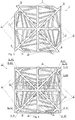
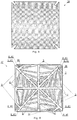
- the present inventions are based on the embodiment of the battery grid 1 ( Figures 1 - 3 ).
- the manufacturing method of the battery grid 1 has been taught earlier in our patent application WO 03/038933 , however, for the sake of completeness this method is described also in the present description together with the apparatus comprising the grid structure manufacturing machine 33 ( Figures 9 - 10 ) and the pasting machine 34 ( Figures 11 - 12 ) for implementing the method.
- the battery grid 1 comprises a grid structure 4 composed of grid arms 2 and bordering arms 3 made of molten lead or lead alloy19, supporting element 5 and lugs 6, as well as lead paste 7 applied on the surface of the supporting element 5 between the grid arms 2 and bordering arms 3.
- the supporting element 5 comprises fibreglass based material.
- the grid structure 4 is fixed to the supporting element 5 through chemical bond formed between the molten lead or lead alloy 19 and the fibreglass material of the supporting element 5.
- the lead paste 7 is secured to the supporting element 5 through chemical bond formed between lead paste 7 and the fiberglass material of the supporting element 5.
- more than one lug 6 is arranged in a given distance - preferably equidistant - from each other along the bordering arm 3. From the lugs 6 grid arms 2 the number of which equals to the number of the lugs 6 are directed preferably to the geometrical centre point of the battery grid 1. Within the bordering arms 3, between the grid arms 2 which are connected to the lugs 6 further internal grid arms 2 are formed. The grid arms 2 are in galvanic connection with each other, with the bordering arms 3 and the lugs 6.
- a disadvantage of the known grids is that when they are exposed merely to a slight mechanical force or because of internal corrosion occurring in the course of time, falling out of the mass consequently short-cut is inevitable.
- the grid structure 4 and lead paste 7 forms such strong chemical bond with the supporting element 5 that the applied lead paste practically cannot be removed. In this manner the internal corrosion is prevented thereby the paste can be retained in its place for a very long time.
- battery grid 1 is centrally symmetric having bordering arms 3 shaping a square in which grid arms 2 are arranged.
- the bordering arms 3 may shape other forms, e.g. a circle or a regular polygon.
- the lugs 6 of battery grid 1 are formed in such a manner that when battery grid 1 is reversely positioned on a normally positioned battery grid 1, the lugs 6 of the reversely positioned battery grid 1 and the lugs 6 of the normally positioned battery grid 1 do not overlap each other ( Figure 4 ).
- Grid structure 4 may also be fixed to one side of the supporting element 5.
- Grid structure 4 not necessarily has the same thickness on the two sides of supporting element 5; grid structure 4 may be fixed to supporting element 5 symmetrically or asymmetrically.
- In the battery grid 1 perpendicular to the plane of the battery grid 1 at least one through bore 9 is formed.
- the apparatus for producing battery grid 1 is applicable for producing the battery grid structure 4 made of molten lead or lead alloy 19 on the fibreglass based supporting element 5, and for coating the supporting element 5 between the grid structure 4 with lead paste 7.
- the apparatus comprises a manufacturing machine 33 producing the grid structure 4 ( Figure 9 ) and a pasting machine 34 producing the battery grid 1 ( Figure 12 ).
- a pair of pressing cylinders 10 having parallel shafts rotated inversely at a constant speed and kept warm are arranged in manufacturing machine 33.
- On the superficies 11 of pressing cylinders 10 an endless first pressing belt 15 and second pressing belt 16 moving at a speed corresponding to the circumferential speed of the pressing cylinders 10 is arranged respectively. In the material of the pressing belts 15, 16 patterns 12 are formed.
- Patterns 12 represent the negative patterns of grid arms 2 and bordering arms 3 of battery grid 1.
- Patterns 12 of the first pressing belt 15 are the reflected images of the patterns 12 of the second pressing belt 16.
- the individual patterns 12 formed in first pressing belt 15 are arranged in such a manner that they overlap the respective patterns 12 in the second pressing belt 16.
- On opposite sides of the pressing belts 15, 16 a heating tunnel 13 is arranged which heats the pressing belts 15, 16 to a temperature of 150 - 350 °C.
- a cooling tunnel 21 is provided for cooling the sides of the pressing belts 15, 16 facing each other.
- the fibreglass based supporting element 5 is guided through between the pressing belts 15, 16.
- molten lead or lead alloy 19 is fed through a pipe 18 in between the pressing belts 15, 16, basically into the patterns 12 coated with some non-stick material so that molten lead or lead alloy 19 does not stick to patterns 12.
- Molten lead or lead alloy 19 is fixed to supporting element 5 in the form of the grid structure 4 of the battery grid 1 as determined by patterns 12 through the chemical bond formed between the supporting element 5 and the molten lead or lead alloy 19.
- Battery grid net 20 produced between pressing belts 15, 16 in this manner is guided through the cooling tunnel 21. Then it is guided in between forced coupled pasting cylinders 22, 23 of the pasting machine 34.
- the pasting machine 34 has a first pasting cylinder 22 and a second pasting cylinder 23 having parallel shafts rotating inversely.
- plane figures 26 having an outline 25 agreeing with the perimeter of the battery grid 1 are formed as recesses 27 and/or protrusions 28.
- the distance 29 between the plane figures 26 corresponds to the distance 29 between the battery grids 1 in the battery grid net 20.
- cutting edge 31 is provided.
- Pasting cylinders 22, 23 are matched to each other in such a manner that the plane figures 26 formed on the superficies 24 of the first pasting cylinder 22 overlap the respective plane figures 26 formed on the second pasting cylinder 23.
- the total depth of the overlapping plane figures 26 of the first and second pasting cylinders 22, 23 corresponds to the thickness 30 of battery grid 1.
- Battery grids 1 arranged in the battery grid net 20 are guided in between the plane figures 26 provided on the superficies 24 of the pasting cylinders 22, 23 while lead paste 7 is fed in between pasting cylinders 22, 23 from a paste feeder 32. Molten lead 19 is pressed into the grid structure 4 of battery grid 1 by means of pasting cylinders 22, 23.
- the first pressing belt 15 and the second pressing belt 16 move on the superficies 11 of the pair of the inversely rotated pressing cylinders 10 having parallel shafts at a speed corresponding to the speed of the superficies 11.
- Pressing belts 15, 16 provided with patterns 12 presenting the negative pattern of the grid structure 4 of battery grid 1 are guided through heating tunnel 13 at 150 - 350 °C.
- the fibreglass based supporting element 5 is introduced in between the first pressing belt 15 and the second pressing belt 16 while the molten lead or lead alloy 19 is fed between the belts 15, 16 through a pipe 18 by means of a liquid metal pump, basically into the patterns 12 coated with some non-stick material so that molten lead or lead alloy 19 does not stick to patterns 12. Flowing of the molten lead 19 to the sides is prevented by means of flanges 43. Molten lead or lead alloy 19 is fixed to supporting element 5 through chemical bond formed between the supporting element 5 and the molten lead or lead alloy 19. Battery grid net 20 produced in this manner is gradually cooled down by guiding it through the cooling tunnel 21 so that the grid structure 4 of battery grid 1 solidifies.
- the battery grid net 20 is guided in between the forced coupled, inversely rotated first pasting cylinder 22 and second pasting cylinder 23 having parallel shafts.
- Battery grid net 20 is guided through pasting cylinders 22, 23 in such a manner that the battery grids 1 arranged in battery grid net 20 get in between the plane figures 26 formed on the superficies 24 of the pasting cylinders 22, 23.
- lead paste 7 is fed from paste feeder 32 onto battery grid 20 and is pressed into the grid structure 4 of battery grid 1 by means of pasting cylinders 22, 23.
- lead paste 7 is fixed to supporting element 5 through chemical bond formed between the fibreglass based supporting element 5 and lead paste 7.
- Battery grid 1 provided with the lead paste 7 is cut out by means of cutting edges 31.
- the heat controlled heating tunnel 13 and cooling tunnel 21 make it possible to cast a grid structure 4 having optional thickness 30, even a thickness of 0.10 mm.
- After winding off the fibreglass based supporting element 5 from the coil it is guided over a guiding cylinder and through the endless pressing belts 15, 16 while molten lead 19 flows into the trough between pressing belts 15, 16.
- At the ends of the trough flanges 43 are positioned in order to keep molten lead 19 in between the pressing belts 15, 16.
- the recesses formed by the patterns 12 etched or pressed in pressing belts 15, 16 i.e. by means of the negative grid patterns supporting element 5 can be drawn in at a constant speed.
- the surface of the entering fibreglass based supporting element 5 is treated with heat (at 250 - 300 °C) for a few tenths of a second.
- Supporting element 5 is guided from above through the space formed by the inversely rotating pressing belts 15, 16 and the continuously heat controlled flanges 43.
- pressing belts 15, 16 and the matching flanges 43 define a basin. Because of lead fume this system is covered with a closed unit. From melting apparatus arranged in the vicinity of the system molten lead with a determined temperature is pressed onto the inversely rotated pressing belts 15, 16 by means of a pump through two parallel pipes 18 having appropriate diameters and evenly spaced perforations.
- a level and heat sensor is provided for setting the optimal dosing speed and amount of lead to be fed.
- the known apparatuses are not shown in the Figures.
- lead and in all of its alloys there is always some oxygen present in the form of lead-oxide at molecular thickness of layer. With free silicate anions that can be found on the surface of the fibreglass, this layer forms lead-silicates. This process creates a strong mechanical bond between the lead material of the grid and the fibreglass as well as between the lead paste and the fibreglass. This bond will continuously grow stronger hour by hour, so a week seasoning may be beneficial.
- the fibreglass based material of the supporting element 5 will form a strong physical and chemical bond with the molten lead or lead alloy 19 while the superficies 11 prevent it from adhering onto the remaining surface, it will peel off. In this way all of the parameters of the product can be determined precisely in advance.
- the battery grid 1 is not hardened yet. Therefore by means of pressing cylinders 10 the pressing belts 15, 16 having the molten lead 19 and the fibreglass based supporting element 5 in between run into and travel through cooling tunnel 19.
- the patterns 12 are continuously kept tightly closed the profile is entirely and hermetically filled with the molten lead 19. Cooling tunnel 21 is controlled by zones. Getting closer to the end of the process the individual zones cool the pressing belts 15, 16 by continuously decreasing direct contact heat transfer.
- the sheet-like fibreglass based supporting element 5 optional number of grid structure may be produced parallel with each other depending on the width of the pressing belts 15, 16 and the supporting element 5.
- the grid structures 4 produced in this manner have an even and uniform thickness 30 corresponding to the patterns 12 etched into the superficies of pressing belts 15, 16.
- Supporting element 5 comes into the mid-plane of the grid structure 4. However, if required, it may be positioned only on one of its sides or shifted from its mid-plane.
- Battery grid net 20 may be re-wound for further transportation or may be directed to the pasting machine 34 where it can be coated again continuously with lead paste 7. Then battery grids 1 may be cut to size either before drying or at any time following it. With optimal measurement with a machine having a width of 2 metres in which a pair of 150 cm wide pressing belts 15, 16 running on the superficies 11 of a pair of pressing cylinders 10 each having a diameter of 30 cm is used then guided through the heat treating tunnels at low rpm, approximately 400 000 grid per hour can be produced.
- the lead mass can be decreased to one-third of the presently used lead mass.
- the entire surface of the supporting element 5 in grid structure 4 forms a strong physical and at the same time definite chemical bond with the lead paste 7. Practically, the two materials cannot be pulled apart again and the lead paste can be retained definitely.
- Synchronized rotation of the two pasting cylinders 22, 23 is ensured by the common driving shaft and a pair of cogwheels driven by motor 17.
- the finished battery grid net 20 leaving the production line is guided in a form-fitting way to the first pasting cylinders 22 of the pair of pasting cylinders 22, 23 whose revolution per minute and diameter equals to that of the pressing cylinders 10 of manufacturing machine 33 so that each of the grid structures 4 fit in a respective recess 27. Then it is rotated so as to match against a respective positive pattern that is a protrusion 28 of the second pasting cylinder 23. Simultaneously with synchronized rotating of the cylinders properly mixed lead paste 7 is introduced in between pasting cylinders 22, 23 from a paste feeder 32 positioned above.
- protrusion 28 rolls into recess 27 and presses the properly dense lead paste into the grid structure 4.
- the space created between recess 27 and protrusion 28 determines the total thickness 30 of the grid structure 4 coated with lead paste 7.
- paste cylinders 22, 23 work as a cutter, too.
- hard metal can be used for example hard chromium plated steel.
- the angularly properly formed cutting edges 31 precisely meet and cut the material when cylinders 22, 23 lock up, so battery grids 1 pasted with the lead are punched out from battery grid net 20.
- the pattern halves come apart and battery grids 1 from the parting halves get onto a moving conveyor belt 14 positioned underneath.
- the fibreglass based supporting element 5 which remains after punching out of the battery grids 1, which is now holed like a net, is wound up by means of a separately driven cylinder positioned above the belt. 100% of this remaining material may be reused.
- the present invention also relates to a battery cell 35 formed from the battery grids 1 ( Figure 7 ).
- the battery cell 35 comprises positive and negative polarity battery grids 1 placed in a battery housing 36 filled with battery acid. Between the battery grids 1 separator plates 38 ( Figure 5 ) are placed.
- the pair of battery grids 37 comprises two identically formed battery grids, namely a first battery grid 44 and a second battery grid 45 placed on each other reversely in such a manner that their bordering arms 3 overlap each other but the lugs 6 of the battery grids 1 are formed in such a manner that lugs 41 of the reversed second battery grid 45 and the lugs 40 of the first battery grid 44 do not overlap each other.
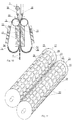
- the separator plates 38 are inserted in between the battery grids 1 ( Figure 6 ).
- the battery cell 35 comprises several pairs of battery grids 37 insulated from each other by the separator plates 38 ( Figure 7 ).
- the separator plates 38 between the pairs of battery grids 37 are not shown in Figure 7 but naturally, the individual pairs of battery grids 37 are insulated from each other by means of separator plates 38 as it is shown in Figure 6 .
- the overlapping pairs of battery grids 37 are arranged in parallel planes, on a common axis which is vertical to their planes in such a manner that lugs 6, 40 of each of the first battery grids 44 are connected with each other galvanically and lugs 6, 41 of each of the second battery grids 45 are also connected with each other galvanically by means of the joining element 8.
- the battery grid system 39 built in this manner is placed in the battery housing 36 filled with battery acid.
- the lugs 40 connected to joining element 8 and lugs 41 connected to joining element 8 respectively are polarized differently, either positively or negatively.
- the joining elements 8 having the same polarity are also connected to each other (this is not shown in the Figures as it is clear for those skilled in the art).
- the present invention further relates to a storage battery 42 comprising the above described battery cells 35 ( Figure 8 ).
- the storage battery 42 comprises several battery cells 35 formed from battery grid systems 39 and placed in a battery housing 36.
- the battery cells 35 in the storage battery 42 are electrically connected with each other serially or parallel according to their polarity.
- the same polarity joining elements 8 are also coupled with each other (this is not shown in the Figures as it is clear for those skilled in the art).
- Storage battery 42 preferably comprises optional number of approximately 2 V battery cells 35, depending on the amount of voltage required for the storage battery.
- the whole amount of active energy on the surface of battery grid 1 can be accessed.
- the whole amount of active energy stored on battery grid 1 can be utilized, drawn out, transferred or charged in a greater extent.
- the charging time of the storage battery 42 and also delivery of current is decreased significantly. With the application of separator plates 38 space is gained, the chemical processes can take place in a shorter time between the grids.
- the advantage of the present invention is that industrial production of a grid having an optional thickness, even a thickness of 0.1 mm becomes possible. Practically, the environmentally harmful and expensive technology, casting of the lead grid, production of calcium or other pre-alloy can be replaced by the solution of the present invention.
- the pure lead or lead alloy material of the grid is reinforced with a fibreglass insert.
- the mechanical strength of the battery grid formed on the fibreglass based supporting element is orders of magnitude better than in case of any known solutions.
- the lead paste is retained on the entire surface of the supporting element.
- the fibreglass based supporting element will keep the lead mass through strong physical and chemical bond so coming off or peeling off the lead mass from the grid is prevented. Even external or internal mechanical deformation, sudden deflecting force will not cause coming off the lead mass.
- the fibreglass based supporting element is not fragile. All the parameters of the battery grid according to the invention can be optionally chosen. Transportation or further processing becomes significantly faster, easier and more economical. Safe and cheap mass production of precise, 0.1 - 0.5 mm thin or thicker grids becomes possible.
- the module system ensures that a cell can be replaced quickly and easily in case of its failure.
- the storage battery according to the present invention is resistant to general physical impacts. The cost of manufacture is significantly decreased. By dividing the surface of the grid into segments the current paths in the battery grid are optimized. In this manner the energy generated during the same time on the different surface areas of the battery grid can be accessed simultaneously through several current paths. Further, the through-bore in the middle of the grid structure increases the space of acid and promotes the chemical processes.
- the whole amount of the active energy of the surface of the battery grid can be utilized, drawn out, transferred or charged as opposed to the known battery grids.
- the known battery grids have only one lug which involves great loss of current.
- By providing several lugs the energy generated on the surface of the grid can be accessed through several paths.
- the battery can receive the energy through several lugs.
- the charging time and also delivery of current is decreased significantly.
- the storage battery according to the present invention may be charged even in half an hour due to the several lugs.
- filling in the patterns is performed at optimal temperature which is essential for producing a 0.1 - 0.5 mm thick grid.
- Heat stabilization is solved at the output which is also essential for producing a 0.1 - 0.5 mm thick grid. Due to the precise technology exactly the same grids can be produced. In this manner the internal energy compensation between the cells can be eliminated.
- the current paths can be divided optimally within the grid, as a result of which each of the lugs and the internal surface are evenly, simultaneously engaged in charging as well as discharging. The method is significantly cheaper, faster than the known methods. It is environmentally safe, and provides a much higher quality.
Landscapes
- Chemical & Material Sciences (AREA)
- Chemical Kinetics & Catalysis (AREA)
- Electrochemistry (AREA)
- General Chemical & Material Sciences (AREA)
- Engineering & Computer Science (AREA)
- Manufacturing & Machinery (AREA)
- Mechanical Engineering (AREA)
- Cell Electrode Carriers And Collectors (AREA)
Priority Applications (2)
| Application Number | Priority Date | Filing Date | Title |
|---|---|---|---|
| PL15744330T PL3146577T3 (pl) | 2014-05-20 | 2015-05-19 | Kratka akumulatorowa, ogniwo akumulatorowe zawierające kratki akumulatorowe oraz bateria akumulatorowa zawierająca ogniwa akumulatorowe |
| RS20181173A RS57855B1 (sr) | 2014-05-20 | 2015-05-19 | Baterijska rešetka, baterijska ćelija koja obuhvata baterijske rešetke i akumulatorska baterija koja obuhvata baterijske ćelije |
Applications Claiming Priority (2)
| Application Number | Priority Date | Filing Date | Title |
|---|---|---|---|
| HU1400252A HU230572B1 (hu) | 2014-05-20 | 2014-05-20 | Akkumulátorrács kialakítás, az akkumulátorrácsokkal kialakított akkumulátor cella és az akkumulátor cellákkal kialakított akkumulátor |
| PCT/HU2015/000046 WO2015177578A1 (en) | 2014-05-20 | 2015-05-19 | Battery grid, battery cell comprising the battery grids and storage battery comprising the battery cells |
Publications (2)
| Publication Number | Publication Date |
|---|---|
| EP3146577A1 EP3146577A1 (en) | 2017-03-29 |
| EP3146577B1 true EP3146577B1 (en) | 2018-07-11 |
Family
ID=89991494
Family Applications (1)
| Application Number | Title | Priority Date | Filing Date |
|---|---|---|---|
| EP15744330.0A Active EP3146577B1 (en) | 2014-05-20 | 2015-05-19 | Battery grid, battery cell comprising the battery grids and storage battery comprising the battery cells |
Country Status (8)
| Country | Link |
|---|---|
| US (1) | US10199656B2 (pl) |
| EP (1) | EP3146577B1 (pl) |
| AU (1) | AU2015263063B2 (pl) |
| ES (1) | ES2690448T3 (pl) |
| HU (1) | HU230572B1 (pl) |
| PL (1) | PL3146577T3 (pl) |
| RS (1) | RS57855B1 (pl) |
| WO (1) | WO2015177578A1 (pl) |
Families Citing this family (5)
| Publication number | Priority date | Publication date | Assignee | Title |
|---|---|---|---|---|
| CN108336368B (zh) * | 2017-12-28 | 2020-09-01 | 广州倬粤动力新能源有限公司 | 板栅的包芯编织方法 |
| CN109980175A (zh) * | 2017-12-28 | 2019-07-05 | 广州倬粤动力新能源有限公司 | 环保碳金水平电池极板组装方法 |
| CN111916683A (zh) * | 2020-07-03 | 2020-11-10 | 界首市南都华宇电源有限公司 | 一种带有铸板余热利用功能的极板固化系统 |
| CN113991183B (zh) * | 2021-10-27 | 2024-03-08 | 上汽时代动力电池系统有限公司 | 一种锂电池结构胶快速摊开设备 |
| CN117497914B (zh) * | 2023-11-09 | 2024-06-28 | 天津大学 | 一种电池簇精细化热管理装置及其控制方法 |
Citations (2)
| Publication number | Priority date | Publication date | Assignee | Title |
|---|---|---|---|---|
| EP2693529A1 (en) * | 2012-07-31 | 2014-02-05 | Johns Manville | Fiber mat for battery plate reinforcement |
| WO2014036090A1 (en) * | 2012-08-28 | 2014-03-06 | Applied Materials, Inc. | Solid state battery fabrication |
Family Cites Families (17)
| Publication number | Priority date | Publication date | Assignee | Title |
|---|---|---|---|---|
| US839711A (en) | 1906-08-15 | 1906-12-25 | Gen Storage Battery Company | Storage-battery plate. |
| GB129425A (en) | 1918-07-08 | 1919-07-08 | Sidney James Williams | Improvements in Electric Accumulators. |
| US3556854A (en) * | 1968-11-29 | 1971-01-19 | Gen Motors Corp | Lead acid storage battery having a grid with divergent fingers |
| US3556853A (en) * | 1969-06-05 | 1971-01-19 | Bell Telephone Labor Inc | Grid for lead-acid cell |
| DE3533581A1 (de) | 1985-09-20 | 1987-04-02 | Varta Batterie | Giessform zur herstellung von gitterplatten fuer bleiakkumulatoren |
| CA2118866A1 (en) * | 1993-06-21 | 1994-12-22 | Clarence A. Meadows | Bipolar battery housing and method |
| US6232018B1 (en) | 1995-08-14 | 2001-05-15 | Baotou Science & Technology Service Corporation | Electrode plate for a lead acid accumulator and its producing method |
| US20020150822A1 (en) * | 2001-02-02 | 2002-10-17 | Marlow John V. | Lightweight composite grid for battery plates |
| WO2003038933A2 (en) | 2001-10-27 | 2003-05-08 | Sarosi Gyoergy Andras | Grid for lead battery, method of manufacturing, and battery plate |
| WO2003079481A1 (en) | 2002-03-05 | 2003-09-25 | Knauer Davis J | Battery with gel blanket |
| EP2389698B1 (en) * | 2009-01-21 | 2017-10-04 | Advanced Battery Concepts, Llc | Bipolar battery assembly |
| US20110206956A1 (en) * | 2010-02-22 | 2011-08-25 | Lineage Power Corporation | Round cell battery |
| CN102640334B (zh) * | 2010-10-18 | 2014-09-17 | 新神户电机株式会社 | 铅蓄电池 |
| US9368800B2 (en) * | 2011-09-12 | 2016-06-14 | Oak Press Solutions Inc. | Stamped battery grid with kinked grid wires |
| US9595360B2 (en) * | 2012-01-13 | 2017-03-14 | Energy Power Systems LLC | Metallic alloys having amorphous, nano-crystalline, or microcrystalline structure |
| US9263721B2 (en) * | 2012-01-13 | 2016-02-16 | Energy Power Systems LLC | Lead-acid battery design having versatile form factor |
| EP2747179B1 (en) * | 2012-09-10 | 2017-09-27 | GS Yuasa International Ltd. | Lattice for storage battery, method for producing lattice for storage battery, and storage battery using lattice for storage battery |
-
2014
- 2014-05-20 HU HU1400252A patent/HU230572B1/hu unknown
-
2015
- 2015-05-19 US US15/312,989 patent/US10199656B2/en active Active
- 2015-05-19 RS RS20181173A patent/RS57855B1/sr unknown
- 2015-05-19 EP EP15744330.0A patent/EP3146577B1/en active Active
- 2015-05-19 WO PCT/HU2015/000046 patent/WO2015177578A1/en not_active Ceased
- 2015-05-19 AU AU2015263063A patent/AU2015263063B2/en not_active Ceased
- 2015-05-19 PL PL15744330T patent/PL3146577T3/pl unknown
- 2015-05-19 ES ES15744330.0T patent/ES2690448T3/es active Active
Patent Citations (2)
| Publication number | Priority date | Publication date | Assignee | Title |
|---|---|---|---|---|
| EP2693529A1 (en) * | 2012-07-31 | 2014-02-05 | Johns Manville | Fiber mat for battery plate reinforcement |
| WO2014036090A1 (en) * | 2012-08-28 | 2014-03-06 | Applied Materials, Inc. | Solid state battery fabrication |
Also Published As
| Publication number | Publication date |
|---|---|
| AU2015263063A1 (en) | 2017-01-12 |
| US20170179496A1 (en) | 2017-06-22 |
| PL3146577T3 (pl) | 2018-12-31 |
| WO2015177578A1 (en) | 2015-11-26 |
| AU2015263063B2 (en) | 2019-11-21 |
| HU230572B1 (hu) | 2016-12-28 |
| ES2690448T3 (es) | 2018-11-21 |
| HUP1400252A2 (en) | 2015-11-30 |
| RS57855B1 (sr) | 2018-12-31 |
| US10199656B2 (en) | 2019-02-05 |
| EP3146577A1 (en) | 2017-03-29 |
Similar Documents
| Publication | Publication Date | Title |
|---|---|---|
| EP3146577B1 (en) | Battery grid, battery cell comprising the battery grids and storage battery comprising the battery cells | |
| US11539051B2 (en) | Battery grid with varied corrosion resistance | |
| TW461134B (en) | Battery grids | |
| WO1996010272A1 (en) | Multi-layered battery grids and method | |
| CA2010766A1 (en) | Method for the manufacture of lead-acid batteries and an associated apparatus and associated lead-acid battery | |
| KR20140029808A (ko) | 전극 조립체의 권취 장치 | |
| KR20130088476A (ko) | 전극판 제조 시스템 및 전극판 제조 방법 | |
| KR102175388B1 (ko) | 이차전지용 전극의 제조방법 및 제조장치 | |
| KR101956935B1 (ko) | 권취 장치 및 이를 이용한 권취 방법 | |
| KR100646550B1 (ko) | 이차 전지의 전극판과 이차 전지의 전극판 코팅 장치 | |
| WO2003038933A2 (en) | Grid for lead battery, method of manufacturing, and battery plate | |
| US4299259A (en) | Lead storage battery plates and method of making the same | |
| CN106654387A (zh) | 无枝晶积累的锂负极电池及其运行方法 | |
| KR100250381B1 (ko) | 축전지용 극판에 활물질을 지지하는 방법 및 그 축전지 | |
| US5001025A (en) | Method for electrochemically treating battery plate stock and related product | |
| CN212991149U (zh) | 一种锂电池卷绕机 | |
| KR102154014B1 (ko) | 전기화학소자용 전극 조립체 및 이를 포함하는 전기화학소자 | |
| CN111193077A (zh) | 一种铅酸蓄电池加胶方法 | |
| EP4659934A1 (en) | Secondary battery manufacturing method and secondary battery manufacturing apparatus | |
| KR102920239B1 (ko) | 전극조립체 제조 방법 | |
| EP4648116A1 (en) | Electrode production apparatus and battery cell comprising electrodes produced thereby, and battery pack and vehicle comprising battery cells | |
| KR20260059824A (ko) | 전극 생산 장치 및 이를 사용하여 생산된 전극을 포함하는 배터리 셀 및, 배터리 셀을 포함하는 배터리 팩 및 자동차 | |
| CN103050736A (zh) | 一种锂离子电池的装配方法 | |
| WO2000063987A1 (en) | Lightweight industrial grid and plate, battery incorporating same, and method of making the plate |
Legal Events
| Date | Code | Title | Description |
|---|---|---|---|
| STAA | Information on the status of an ep patent application or granted ep patent |
Free format text: STATUS: THE INTERNATIONAL PUBLICATION HAS BEEN MADE |
|
| PUAI | Public reference made under article 153(3) epc to a published international application that has entered the european phase |
Free format text: ORIGINAL CODE: 0009012 |
|
| STAA | Information on the status of an ep patent application or granted ep patent |
Free format text: STATUS: REQUEST FOR EXAMINATION WAS MADE |
|
| 17P | Request for examination filed |
Effective date: 20161216 |
|
| AK | Designated contracting states |
Kind code of ref document: A1 Designated state(s): AL AT BE BG CH CY CZ DE DK EE ES FI FR GB GR HR HU IE IS IT LI LT LU LV MC MK MT NL NO PL PT RO RS SE SI SK SM TR |
|
| AX | Request for extension of the european patent |
Extension state: BA ME |
|
| DAV | Request for validation of the european patent (deleted) | ||
| DAX | Request for extension of the european patent (deleted) | ||
| REG | Reference to a national code |
Ref country code: DE Ref legal event code: R079 Ref document number: 602015013481 Country of ref document: DE Free format text: PREVIOUS MAIN CLASS: H01M0004160000 Ipc: H01M0002280000 |
|
| GRAP | Despatch of communication of intention to grant a patent |
Free format text: ORIGINAL CODE: EPIDOSNIGR1 |
|
| STAA | Information on the status of an ep patent application or granted ep patent |
Free format text: STATUS: GRANT OF PATENT IS INTENDED |
|
| RIC1 | Information provided on ipc code assigned before grant |
Ipc: H01M 4/16 20060101ALI20180111BHEP Ipc: H01M 4/14 20060101ALI20180111BHEP Ipc: H01M 4/84 20060101ALI20180111BHEP Ipc: H01M 10/14 20060101ALI20180111BHEP Ipc: H01M 4/73 20060101ALI20180111BHEP Ipc: H01M 2/28 20060101AFI20180111BHEP |
|
| INTG | Intention to grant announced |
Effective date: 20180207 |
|
| GRAS | Grant fee paid |
Free format text: ORIGINAL CODE: EPIDOSNIGR3 |
|
| GRAA | (expected) grant |
Free format text: ORIGINAL CODE: 0009210 |
|
| STAA | Information on the status of an ep patent application or granted ep patent |
Free format text: STATUS: THE PATENT HAS BEEN GRANTED |
|
| AK | Designated contracting states |
Kind code of ref document: B1 Designated state(s): AL AT BE BG CH CY CZ DE DK EE ES FI FR GB GR HR HU IE IS IT LI LT LU LV MC MK MT NL NO PL PT RO RS SE SI SK SM TR |
|
| REG | Reference to a national code |
Ref country code: GB Ref legal event code: FG4D |
|
| REG | Reference to a national code |
Ref country code: CH Ref legal event code: EP |
|
| REG | Reference to a national code |
Ref country code: AT Ref legal event code: REF Ref document number: 1017840 Country of ref document: AT Kind code of ref document: T Effective date: 20180715 |
|
| REG | Reference to a national code |
Ref country code: IE Ref legal event code: FG4D |
|
| REG | Reference to a national code |
Ref country code: DE Ref legal event code: R096 Ref document number: 602015013481 Country of ref document: DE |
|
| REG | Reference to a national code |
Ref country code: SE Ref legal event code: TRGR |
|
| REG | Reference to a national code |
Ref country code: NL Ref legal event code: FP |
|
| REG | Reference to a national code |
Ref country code: ES Ref legal event code: FG2A Ref document number: 2690448 Country of ref document: ES Kind code of ref document: T3 Effective date: 20181121 |
|
| REG | Reference to a national code |
Ref country code: LT Ref legal event code: MG4D |
|
| REG | Reference to a national code |
Ref country code: AT Ref legal event code: MK05 Ref document number: 1017840 Country of ref document: AT Kind code of ref document: T Effective date: 20180711 |
|
| PG25 | Lapsed in a contracting state [announced via postgrant information from national office to epo] |
Ref country code: BG Free format text: LAPSE BECAUSE OF FAILURE TO SUBMIT A TRANSLATION OF THE DESCRIPTION OR TO PAY THE FEE WITHIN THE PRESCRIBED TIME-LIMIT Effective date: 20181011 Ref country code: LT Free format text: LAPSE BECAUSE OF FAILURE TO SUBMIT A TRANSLATION OF THE DESCRIPTION OR TO PAY THE FEE WITHIN THE PRESCRIBED TIME-LIMIT Effective date: 20180711 Ref country code: FI Free format text: LAPSE BECAUSE OF FAILURE TO SUBMIT A TRANSLATION OF THE DESCRIPTION OR TO PAY THE FEE WITHIN THE PRESCRIBED TIME-LIMIT Effective date: 20180711 Ref country code: IS Free format text: LAPSE BECAUSE OF FAILURE TO SUBMIT A TRANSLATION OF THE DESCRIPTION OR TO PAY THE FEE WITHIN THE PRESCRIBED TIME-LIMIT Effective date: 20181111 Ref country code: GR Free format text: LAPSE BECAUSE OF FAILURE TO SUBMIT A TRANSLATION OF THE DESCRIPTION OR TO PAY THE FEE WITHIN THE PRESCRIBED TIME-LIMIT Effective date: 20181012 Ref country code: NO Free format text: LAPSE BECAUSE OF FAILURE TO SUBMIT A TRANSLATION OF THE DESCRIPTION OR TO PAY THE FEE WITHIN THE PRESCRIBED TIME-LIMIT Effective date: 20181011 Ref country code: AT Free format text: LAPSE BECAUSE OF FAILURE TO SUBMIT A TRANSLATION OF THE DESCRIPTION OR TO PAY THE FEE WITHIN THE PRESCRIBED TIME-LIMIT Effective date: 20180711 |
|
| PG25 | Lapsed in a contracting state [announced via postgrant information from national office to epo] |
Ref country code: HR Free format text: LAPSE BECAUSE OF FAILURE TO SUBMIT A TRANSLATION OF THE DESCRIPTION OR TO PAY THE FEE WITHIN THE PRESCRIBED TIME-LIMIT Effective date: 20180711 Ref country code: AL Free format text: LAPSE BECAUSE OF FAILURE TO SUBMIT A TRANSLATION OF THE DESCRIPTION OR TO PAY THE FEE WITHIN THE PRESCRIBED TIME-LIMIT Effective date: 20180711 Ref country code: LV Free format text: LAPSE BECAUSE OF FAILURE TO SUBMIT A TRANSLATION OF THE DESCRIPTION OR TO PAY THE FEE WITHIN THE PRESCRIBED TIME-LIMIT Effective date: 20180711 |
|
| REG | Reference to a national code |
Ref country code: SK Ref legal event code: T3 Ref document number: E 28936 Country of ref document: SK |
|
| REG | Reference to a national code |
Ref country code: DE Ref legal event code: R097 Ref document number: 602015013481 Country of ref document: DE |
|
| PG25 | Lapsed in a contracting state [announced via postgrant information from national office to epo] |
Ref country code: CZ Free format text: LAPSE BECAUSE OF FAILURE TO SUBMIT A TRANSLATION OF THE DESCRIPTION OR TO PAY THE FEE WITHIN THE PRESCRIBED TIME-LIMIT Effective date: 20180711 Ref country code: RO Free format text: LAPSE BECAUSE OF FAILURE TO SUBMIT A TRANSLATION OF THE DESCRIPTION OR TO PAY THE FEE WITHIN THE PRESCRIBED TIME-LIMIT Effective date: 20180711 Ref country code: EE Free format text: LAPSE BECAUSE OF FAILURE TO SUBMIT A TRANSLATION OF THE DESCRIPTION OR TO PAY THE FEE WITHIN THE PRESCRIBED TIME-LIMIT Effective date: 20180711 |
|
| PLBE | No opposition filed within time limit |
Free format text: ORIGINAL CODE: 0009261 |
|
| STAA | Information on the status of an ep patent application or granted ep patent |
Free format text: STATUS: NO OPPOSITION FILED WITHIN TIME LIMIT |
|
| PG25 | Lapsed in a contracting state [announced via postgrant information from national office to epo] |
Ref country code: SM Free format text: LAPSE BECAUSE OF FAILURE TO SUBMIT A TRANSLATION OF THE DESCRIPTION OR TO PAY THE FEE WITHIN THE PRESCRIBED TIME-LIMIT Effective date: 20180711 Ref country code: DK Free format text: LAPSE BECAUSE OF FAILURE TO SUBMIT A TRANSLATION OF THE DESCRIPTION OR TO PAY THE FEE WITHIN THE PRESCRIBED TIME-LIMIT Effective date: 20180711 |
|
| 26N | No opposition filed |
Effective date: 20190412 |
|
| PG25 | Lapsed in a contracting state [announced via postgrant information from national office to epo] |
Ref country code: SI Free format text: LAPSE BECAUSE OF FAILURE TO SUBMIT A TRANSLATION OF THE DESCRIPTION OR TO PAY THE FEE WITHIN THE PRESCRIBED TIME-LIMIT Effective date: 20180711 |
|
| REG | Reference to a national code |
Ref country code: CH Ref legal event code: PL |
|
| PG25 | Lapsed in a contracting state [announced via postgrant information from national office to epo] |
Ref country code: MC Free format text: LAPSE BECAUSE OF FAILURE TO SUBMIT A TRANSLATION OF THE DESCRIPTION OR TO PAY THE FEE WITHIN THE PRESCRIBED TIME-LIMIT Effective date: 20180711 Ref country code: CH Free format text: LAPSE BECAUSE OF NON-PAYMENT OF DUE FEES Effective date: 20190531 Ref country code: LI Free format text: LAPSE BECAUSE OF NON-PAYMENT OF DUE FEES Effective date: 20190531 |
|
| REG | Reference to a national code |
Ref country code: BE Ref legal event code: MM Effective date: 20190531 |
|
| PG25 | Lapsed in a contracting state [announced via postgrant information from national office to epo] |
Ref country code: LU Free format text: LAPSE BECAUSE OF NON-PAYMENT OF DUE FEES Effective date: 20190519 |
|
| PG25 | Lapsed in a contracting state [announced via postgrant information from national office to epo] |
Ref country code: IE Free format text: LAPSE BECAUSE OF NON-PAYMENT OF DUE FEES Effective date: 20190519 |
|
| PG25 | Lapsed in a contracting state [announced via postgrant information from national office to epo] |
Ref country code: BE Free format text: LAPSE BECAUSE OF NON-PAYMENT OF DUE FEES Effective date: 20190531 |
|
| PG25 | Lapsed in a contracting state [announced via postgrant information from national office to epo] |
Ref country code: PT Free format text: LAPSE BECAUSE OF FAILURE TO SUBMIT A TRANSLATION OF THE DESCRIPTION OR TO PAY THE FEE WITHIN THE PRESCRIBED TIME-LIMIT Effective date: 20181111 |
|
| REG | Reference to a national code |
Ref country code: DE Ref legal event code: R079 Ref document number: 602015013481 Country of ref document: DE Free format text: PREVIOUS MAIN CLASS: H01M0002280000 Ipc: H01M0050541000 |
|
| PG25 | Lapsed in a contracting state [announced via postgrant information from national office to epo] |
Ref country code: CY Free format text: LAPSE BECAUSE OF FAILURE TO SUBMIT A TRANSLATION OF THE DESCRIPTION OR TO PAY THE FEE WITHIN THE PRESCRIBED TIME-LIMIT Effective date: 20180711 |
|
| PG25 | Lapsed in a contracting state [announced via postgrant information from national office to epo] |
Ref country code: HU Free format text: LAPSE BECAUSE OF FAILURE TO SUBMIT A TRANSLATION OF THE DESCRIPTION OR TO PAY THE FEE WITHIN THE PRESCRIBED TIME-LIMIT; INVALID AB INITIO Effective date: 20150519 Ref country code: MT Free format text: LAPSE BECAUSE OF FAILURE TO SUBMIT A TRANSLATION OF THE DESCRIPTION OR TO PAY THE FEE WITHIN THE PRESCRIBED TIME-LIMIT Effective date: 20180711 |
|
| PG25 | Lapsed in a contracting state [announced via postgrant information from national office to epo] |
Ref country code: MK Free format text: LAPSE BECAUSE OF FAILURE TO SUBMIT A TRANSLATION OF THE DESCRIPTION OR TO PAY THE FEE WITHIN THE PRESCRIBED TIME-LIMIT Effective date: 20180711 |
|
| PGFP | Annual fee paid to national office [announced via postgrant information from national office to epo] |
Ref country code: NL Payment date: 20250526 Year of fee payment: 11 |
|
| PGFP | Annual fee paid to national office [announced via postgrant information from national office to epo] |
Ref country code: PL Payment date: 20250429 Year of fee payment: 11 Ref country code: DE Payment date: 20250528 Year of fee payment: 11 |
|
| PGFP | Annual fee paid to national office [announced via postgrant information from national office to epo] |
Ref country code: GB Payment date: 20250520 Year of fee payment: 11 Ref country code: ES Payment date: 20250612 Year of fee payment: 11 |
|
| PGFP | Annual fee paid to national office [announced via postgrant information from national office to epo] |
Ref country code: RS Payment date: 20250430 Year of fee payment: 11 |
|
| PGFP | Annual fee paid to national office [announced via postgrant information from national office to epo] |
Ref country code: IT Payment date: 20250522 Year of fee payment: 11 |
|
| PGFP | Annual fee paid to national office [announced via postgrant information from national office to epo] |
Ref country code: FR Payment date: 20250526 Year of fee payment: 11 |
|
| PGFP | Annual fee paid to national office [announced via postgrant information from national office to epo] |
Ref country code: TR Payment date: 20250430 Year of fee payment: 11 Ref country code: SK Payment date: 20250429 Year of fee payment: 11 |
|
| PGFP | Annual fee paid to national office [announced via postgrant information from national office to epo] |
Ref country code: SE Payment date: 20250526 Year of fee payment: 11 |