EP3146715B1 - Systèmes et procédés de visualisation chirurgicale par réalité induite - Google Patents
Systèmes et procédés de visualisation chirurgicale par réalité induite Download PDFInfo
- Publication number
- EP3146715B1 EP3146715B1 EP15795790.3A EP15795790A EP3146715B1 EP 3146715 B1 EP3146715 B1 EP 3146715B1 EP 15795790 A EP15795790 A EP 15795790A EP 3146715 B1 EP3146715 B1 EP 3146715B1
- Authority
- EP
- European Patent Office
- Prior art keywords
- image
- virtual camera
- view
- field
- sensor elements
- Prior art date
- Legal status (The legal status is an assumption and is not a legal conclusion. Google has not performed a legal analysis and makes no representation as to the accuracy of the status listed.)
- Active
Links
Images


Classifications
-
- H—ELECTRICITY
- H04—ELECTRIC COMMUNICATION TECHNIQUE
- H04N—PICTORIAL COMMUNICATION, e.g. TELEVISION
- H04N13/00—Stereoscopic video systems; Multi-view video systems; Details thereof
- H04N13/30—Image reproducers
- H04N13/332—Displays for viewing with the aid of special glasses or head-mounted displays [HMD]
- H04N13/344—Displays for viewing with the aid of special glasses or head-mounted displays [HMD] with head-mounted left-right displays
-
- A—HUMAN NECESSITIES
- A61—MEDICAL OR VETERINARY SCIENCE; HYGIENE
- A61B—DIAGNOSIS; SURGERY; IDENTIFICATION
- A61B1/00—Instruments for performing medical examinations of the interior of cavities or tubes of the body by visual or photographical inspection, e.g. endoscopes; Illuminating arrangements therefor
- A61B1/00002—Operational features of endoscopes
- A61B1/00004—Operational features of endoscopes characterised by electronic signal processing
- A61B1/00006—Operational features of endoscopes characterised by electronic signal processing of control signals
-
- A—HUMAN NECESSITIES
- A61—MEDICAL OR VETERINARY SCIENCE; HYGIENE
- A61B—DIAGNOSIS; SURGERY; IDENTIFICATION
- A61B1/00—Instruments for performing medical examinations of the interior of cavities or tubes of the body by visual or photographical inspection, e.g. endoscopes; Illuminating arrangements therefor
- A61B1/00002—Operational features of endoscopes
- A61B1/00004—Operational features of endoscopes characterised by electronic signal processing
- A61B1/00009—Operational features of endoscopes characterised by electronic signal processing of image signals during a use of endoscope
- A61B1/000094—Operational features of endoscopes characterised by electronic signal processing of image signals during a use of endoscope extracting biological structures
-
- A—HUMAN NECESSITIES
- A61—MEDICAL OR VETERINARY SCIENCE; HYGIENE
- A61B—DIAGNOSIS; SURGERY; IDENTIFICATION
- A61B1/00—Instruments for performing medical examinations of the interior of cavities or tubes of the body by visual or photographical inspection, e.g. endoscopes; Illuminating arrangements therefor
- A61B1/00002—Operational features of endoscopes
- A61B1/00039—Operational features of endoscopes provided with input arrangements for the user
- A61B1/00042—Operational features of endoscopes provided with input arrangements for the user for mechanical operation
-
- A—HUMAN NECESSITIES
- A61—MEDICAL OR VETERINARY SCIENCE; HYGIENE
- A61B—DIAGNOSIS; SURGERY; IDENTIFICATION
- A61B1/00—Instruments for performing medical examinations of the interior of cavities or tubes of the body by visual or photographical inspection, e.g. endoscopes; Illuminating arrangements therefor
- A61B1/00163—Optical arrangements
- A61B1/00174—Optical arrangements characterised by the viewing angles
- A61B1/00181—Optical arrangements characterised by the viewing angles for multiple fixed viewing angles
-
- A—HUMAN NECESSITIES
- A61—MEDICAL OR VETERINARY SCIENCE; HYGIENE
- A61B—DIAGNOSIS; SURGERY; IDENTIFICATION
- A61B1/00—Instruments for performing medical examinations of the interior of cavities or tubes of the body by visual or photographical inspection, e.g. endoscopes; Illuminating arrangements therefor
- A61B1/00163—Optical arrangements
- A61B1/00188—Optical arrangements with focusing or zooming features
-
- A—HUMAN NECESSITIES
- A61—MEDICAL OR VETERINARY SCIENCE; HYGIENE
- A61B—DIAGNOSIS; SURGERY; IDENTIFICATION
- A61B1/00—Instruments for performing medical examinations of the interior of cavities or tubes of the body by visual or photographical inspection, e.g. endoscopes; Illuminating arrangements therefor
- A61B1/00163—Optical arrangements
- A61B1/00193—Optical arrangements adapted for stereoscopic vision
-
- A—HUMAN NECESSITIES
- A61—MEDICAL OR VETERINARY SCIENCE; HYGIENE
- A61B—DIAGNOSIS; SURGERY; IDENTIFICATION
- A61B1/00—Instruments for performing medical examinations of the interior of cavities or tubes of the body by visual or photographical inspection, e.g. endoscopes; Illuminating arrangements therefor
- A61B1/04—Instruments for performing medical examinations of the interior of cavities or tubes of the body by visual or photographical inspection, e.g. endoscopes; Illuminating arrangements therefor combined with photographic or television appliances
- A61B1/045—Control thereof
-
- A—HUMAN NECESSITIES
- A61—MEDICAL OR VETERINARY SCIENCE; HYGIENE
- A61B—DIAGNOSIS; SURGERY; IDENTIFICATION
- A61B1/00—Instruments for performing medical examinations of the interior of cavities or tubes of the body by visual or photographical inspection, e.g. endoscopes; Illuminating arrangements therefor
- A61B1/04—Instruments for performing medical examinations of the interior of cavities or tubes of the body by visual or photographical inspection, e.g. endoscopes; Illuminating arrangements therefor combined with photographic or television appliances
- A61B1/05—Instruments for performing medical examinations of the interior of cavities or tubes of the body by visual or photographical inspection, e.g. endoscopes; Illuminating arrangements therefor combined with photographic or television appliances characterised by the image sensor, e.g. camera, being in the distal end portion
-
- A—HUMAN NECESSITIES
- A61—MEDICAL OR VETERINARY SCIENCE; HYGIENE
- A61B—DIAGNOSIS; SURGERY; IDENTIFICATION
- A61B34/00—Computer-aided surgery; Manipulators or robots specially adapted for use in surgery
- A61B34/20—Surgical navigation systems; Devices for tracking or guiding surgical instruments, e.g. for frameless stereotaxis
-
- A—HUMAN NECESSITIES
- A61—MEDICAL OR VETERINARY SCIENCE; HYGIENE
- A61B—DIAGNOSIS; SURGERY; IDENTIFICATION
- A61B90/00—Instruments, implements or accessories specially adapted for surgery or diagnosis and not covered by any of the groups A61B1/00 - A61B50/00, e.g. for luxation treatment or for protecting wound edges
- A61B90/36—Image-producing devices or illumination devices not otherwise provided for
- A61B90/361—Image-producing devices, e.g. surgical cameras
-
- A—HUMAN NECESSITIES
- A61—MEDICAL OR VETERINARY SCIENCE; HYGIENE
- A61B—DIAGNOSIS; SURGERY; IDENTIFICATION
- A61B90/00—Instruments, implements or accessories specially adapted for surgery or diagnosis and not covered by any of the groups A61B1/00 - A61B50/00, e.g. for luxation treatment or for protecting wound edges
- A61B90/36—Image-producing devices or illumination devices not otherwise provided for
- A61B90/37—Surgical systems with images on a monitor during operation
-
- G—PHYSICS
- G06—COMPUTING OR CALCULATING; COUNTING
- G06F—ELECTRIC DIGITAL DATA PROCESSING
- G06F3/00—Input arrangements for transferring data to be processed into a form capable of being handled by the computer; Output arrangements for transferring data from processing unit to output unit, e.g. interface arrangements
- G06F3/01—Input arrangements or combined input and output arrangements for interaction between user and computer
- G06F3/011—Arrangements for interaction with the human body, e.g. for user immersion in virtual reality
-
- G—PHYSICS
- G06—COMPUTING OR CALCULATING; COUNTING
- G06F—ELECTRIC DIGITAL DATA PROCESSING
- G06F3/00—Input arrangements for transferring data to be processed into a form capable of being handled by the computer; Output arrangements for transferring data from processing unit to output unit, e.g. interface arrangements
- G06F3/14—Digital output to display device ; Cooperation and interconnection of the display device with other functional units
- G06F3/1454—Digital output to display device ; Cooperation and interconnection of the display device with other functional units involving copying of the display data of a local workstation or window to a remote workstation or window so that an actual copy of the data is displayed simultaneously on two or more displays, e.g. teledisplay
-
- H—ELECTRICITY
- H04—ELECTRIC COMMUNICATION TECHNIQUE
- H04N—PICTORIAL COMMUNICATION, e.g. TELEVISION
- H04N13/00—Stereoscopic video systems; Multi-view video systems; Details thereof
-
- H—ELECTRICITY
- H04—ELECTRIC COMMUNICATION TECHNIQUE
- H04N—PICTORIAL COMMUNICATION, e.g. TELEVISION
- H04N13/00—Stereoscopic video systems; Multi-view video systems; Details thereof
- H04N13/10—Processing, recording or transmission of stereoscopic or multi-view image signals
- H04N13/106—Processing image signals
- H04N13/111—Transformation of image signals corresponding to virtual viewpoints, e.g. spatial image interpolation
-
- H—ELECTRICITY
- H04—ELECTRIC COMMUNICATION TECHNIQUE
- H04N—PICTORIAL COMMUNICATION, e.g. TELEVISION
- H04N13/00—Stereoscopic video systems; Multi-view video systems; Details thereof
- H04N13/10—Processing, recording or transmission of stereoscopic or multi-view image signals
- H04N13/106—Processing image signals
- H04N13/156—Mixing image signals
-
- H—ELECTRICITY
- H04—ELECTRIC COMMUNICATION TECHNIQUE
- H04N—PICTORIAL COMMUNICATION, e.g. TELEVISION
- H04N13/00—Stereoscopic video systems; Multi-view video systems; Details thereof
- H04N13/20—Image signal generators
- H04N13/204—Image signal generators using stereoscopic image cameras
- H04N13/239—Image signal generators using stereoscopic image cameras using two two-dimensional [2D] image sensors having a relative position equal to or related to the interocular distance
-
- H—ELECTRICITY
- H04—ELECTRIC COMMUNICATION TECHNIQUE
- H04N—PICTORIAL COMMUNICATION, e.g. TELEVISION
- H04N23/00—Cameras or camera modules comprising electronic image sensors; Control thereof
- H04N23/95—Computational photography systems, e.g. light-field imaging systems
- H04N23/957—Light-field or plenoptic cameras or camera modules
-
- A—HUMAN NECESSITIES
- A61—MEDICAL OR VETERINARY SCIENCE; HYGIENE
- A61B—DIAGNOSIS; SURGERY; IDENTIFICATION
- A61B1/00—Instruments for performing medical examinations of the interior of cavities or tubes of the body by visual or photographical inspection, e.g. endoscopes; Illuminating arrangements therefor
- A61B1/00002—Operational features of endoscopes
- A61B1/00043—Operational features of endoscopes provided with output arrangements
- A61B1/00045—Display arrangement
-
- A—HUMAN NECESSITIES
- A61—MEDICAL OR VETERINARY SCIENCE; HYGIENE
- A61B—DIAGNOSIS; SURGERY; IDENTIFICATION
- A61B17/00—Surgical instruments, devices or methods
- A61B2017/00017—Electrical control of surgical instruments
- A61B2017/00203—Electrical control of surgical instruments with speech control or speech recognition
-
- A—HUMAN NECESSITIES
- A61—MEDICAL OR VETERINARY SCIENCE; HYGIENE
- A61B—DIAGNOSIS; SURGERY; IDENTIFICATION
- A61B17/00—Surgical instruments, devices or methods
- A61B2017/00017—Electrical control of surgical instruments
- A61B2017/00216—Electrical control of surgical instruments with eye tracking or head position tracking control
-
- A—HUMAN NECESSITIES
- A61—MEDICAL OR VETERINARY SCIENCE; HYGIENE
- A61B—DIAGNOSIS; SURGERY; IDENTIFICATION
- A61B34/00—Computer-aided surgery; Manipulators or robots specially adapted for use in surgery
- A61B34/20—Surgical navigation systems; Devices for tracking or guiding surgical instruments, e.g. for frameless stereotaxis
- A61B2034/2046—Tracking techniques
- A61B2034/2048—Tracking techniques using an accelerometer or inertia sensor
-
- A—HUMAN NECESSITIES
- A61—MEDICAL OR VETERINARY SCIENCE; HYGIENE
- A61B—DIAGNOSIS; SURGERY; IDENTIFICATION
- A61B34/00—Computer-aided surgery; Manipulators or robots specially adapted for use in surgery
- A61B34/20—Surgical navigation systems; Devices for tracking or guiding surgical instruments, e.g. for frameless stereotaxis
- A61B2034/2046—Tracking techniques
- A61B2034/2051—Electromagnetic tracking systems
-
- A—HUMAN NECESSITIES
- A61—MEDICAL OR VETERINARY SCIENCE; HYGIENE
- A61B—DIAGNOSIS; SURGERY; IDENTIFICATION
- A61B34/00—Computer-aided surgery; Manipulators or robots specially adapted for use in surgery
- A61B34/20—Surgical navigation systems; Devices for tracking or guiding surgical instruments, e.g. for frameless stereotaxis
- A61B2034/2046—Tracking techniques
- A61B2034/2055—Optical tracking systems
-
- A—HUMAN NECESSITIES
- A61—MEDICAL OR VETERINARY SCIENCE; HYGIENE
- A61B—DIAGNOSIS; SURGERY; IDENTIFICATION
- A61B90/00—Instruments, implements or accessories specially adapted for surgery or diagnosis and not covered by any of the groups A61B1/00 - A61B50/00, e.g. for luxation treatment or for protecting wound edges
- A61B90/30—Devices for illuminating a surgical field, the devices having an interrelation with other surgical devices or with a surgical procedure
- A61B2090/309—Devices for illuminating a surgical field, the devices having an interrelation with other surgical devices or with a surgical procedure using white LEDs
-
- A—HUMAN NECESSITIES
- A61—MEDICAL OR VETERINARY SCIENCE; HYGIENE
- A61B—DIAGNOSIS; SURGERY; IDENTIFICATION
- A61B90/00—Instruments, implements or accessories specially adapted for surgery or diagnosis and not covered by any of the groups A61B1/00 - A61B50/00, e.g. for luxation treatment or for protecting wound edges
- A61B90/36—Image-producing devices or illumination devices not otherwise provided for
- A61B2090/363—Use of fiducial points
-
- A—HUMAN NECESSITIES
- A61—MEDICAL OR VETERINARY SCIENCE; HYGIENE
- A61B—DIAGNOSIS; SURGERY; IDENTIFICATION
- A61B90/00—Instruments, implements or accessories specially adapted for surgery or diagnosis and not covered by any of the groups A61B1/00 - A61B50/00, e.g. for luxation treatment or for protecting wound edges
- A61B90/36—Image-producing devices or illumination devices not otherwise provided for
- A61B2090/364—Correlation of different images or relation of image positions in respect to the body
- A61B2090/365—Correlation of different images or relation of image positions in respect to the body augmented reality, i.e. correlating a live optical image with another image
-
- A—HUMAN NECESSITIES
- A61—MEDICAL OR VETERINARY SCIENCE; HYGIENE
- A61B—DIAGNOSIS; SURGERY; IDENTIFICATION
- A61B90/00—Instruments, implements or accessories specially adapted for surgery or diagnosis and not covered by any of the groups A61B1/00 - A61B50/00, e.g. for luxation treatment or for protecting wound edges
- A61B90/36—Image-producing devices or illumination devices not otherwise provided for
- A61B2090/364—Correlation of different images or relation of image positions in respect to the body
- A61B2090/367—Correlation of different images or relation of image positions in respect to the body creating a 3D dataset from 2D images using position information
-
- A—HUMAN NECESSITIES
- A61—MEDICAL OR VETERINARY SCIENCE; HYGIENE
- A61B—DIAGNOSIS; SURGERY; IDENTIFICATION
- A61B90/00—Instruments, implements or accessories specially adapted for surgery or diagnosis and not covered by any of the groups A61B1/00 - A61B50/00, e.g. for luxation treatment or for protecting wound edges
- A61B90/36—Image-producing devices or illumination devices not otherwise provided for
- A61B90/37—Surgical systems with images on a monitor during operation
- A61B2090/371—Surgical systems with images on a monitor during operation with simultaneous use of two cameras
-
- A—HUMAN NECESSITIES
- A61—MEDICAL OR VETERINARY SCIENCE; HYGIENE
- A61B—DIAGNOSIS; SURGERY; IDENTIFICATION
- A61B90/00—Instruments, implements or accessories specially adapted for surgery or diagnosis and not covered by any of the groups A61B1/00 - A61B50/00, e.g. for luxation treatment or for protecting wound edges
- A61B90/36—Image-producing devices or illumination devices not otherwise provided for
- A61B90/37—Surgical systems with images on a monitor during operation
- A61B2090/372—Details of monitor hardware
-
- A—HUMAN NECESSITIES
- A61—MEDICAL OR VETERINARY SCIENCE; HYGIENE
- A61B—DIAGNOSIS; SURGERY; IDENTIFICATION
- A61B90/00—Instruments, implements or accessories specially adapted for surgery or diagnosis and not covered by any of the groups A61B1/00 - A61B50/00, e.g. for luxation treatment or for protecting wound edges
- A61B90/50—Supports for surgical instruments, e.g. articulated arms
- A61B2090/502—Headgear, e.g. helmet, spectacles
Definitions
- the present technology is generally related to mediated-reality surgical visualization and associated systems and methods.
- several embodiments are directed to head-mounted displays configured to provide mediated-reality output to a wearer for use in surgical applications.
- Traditional surgical loupes suffer from a number of drawbacks. They are customized for each individual surgeon, based on the surgeon's corrective vision requirements and interpupillary distance, and so cannot be shared among surgeons. Traditional surgical loupes are also restricted to a single level of magnification, forcing the surgeon to adapt all of her actions to that level of magnification, or to frequently look "outside" the loupes at odd angles to perform actions where magnification is unhelpful or even detrimental. Traditional loupes provide a sharp image only within a very shallow depth of field, while also offering a relatively narrow field of view. Blind spots are another problem, due to the bulky construction of traditional surgical loupes.
- US2010/045783 discloses methods and systems for dynamic virtual convergence and a video see through head mountable display that uses dynamic virtual convergence are disclosed.
- a dynamic virtual convergence algorithm includes sampling an image with two cameras. The cameras each have a field of view that is larger than a field of view of displays used to display images sampled by the cameras.
- a heuristic is used to estimate the gaze distance of the viewer. The display frustums are transformed so that they converge at the estimated gaze distance.
- the images sampled by the cameras are then reprojected into the transformed display frustums.
- the reprojected images are displayed to the user to simulate viewing of close range objects.
- US2005/203380 discloses a method for augmented reality navigation of a medical intervention includes providing a stereoscopic head mounted display, the display including a pair of stereo viewing cameras, at least one tracking camera, and a stereoscopic guidance display.
- the patient's body pose is determined from a rigid body transformation between the tracking camera and frame markers on the scanning table, and the pose of an intervention instrument with respect to the table is determined.
- a visual representation of the patient overlaid with an image of the intervention target, the instrument, and a path for guiding the instrument to perform said medical intervention is displayed in the stereoscopic guidance display.
- EP1027627 discloses eyeglass interface system which integrates interface systems within eyewear.
- the system includes a display assembly and one or more audio and/or video assemblies mounted to an eyeglass frame.
- the display assembly is mounted to one temple and provides an image which can be viewed by the user.
- the audio or video assembly is mounted to the other temple and is in communication with the display assembly.
- the audio or video assembly may comprise such as microphone and/or speakers.
- a plenoptic camera apparatus includes a main lens unit configured to collect rays emitted from a subject.
- the plenoptic camera apparatus includes an image sensor unit adapted to capture images formed from the collected rays through one or more convertible lens device units.
- the convertible lens device units are positioned between the main lens unit and the image sensor unit and configured to provide individual curvature adjustment.
- the plenoptic camera apparatus includes a control unit configured to control the convertible lens device units to switch to a high-resolution imaging lens or a plenoptic imaging lens array, based on a user's selection, and control driving of the convertible lens device units to compensate for a partial aberration caused by the main lens unit.
- a head-mounted display assembly can include a stereoscopic display device configured to display a three-dimensional image to a user wearing the assembly.
- An imaging device can be coupled to the head-mounted display assembly and configured to capture images to be displayed to the user. Additional image data from other imagers can be incorporated or synthesized into the display.
- mediated-reality refers to the ability to add to, subtract from, or otherwise manipulate the perception of reality through the use of a wearable display.
- “Mediated reality” display includes at least "virtual reality” as well as “augmented reality” type displays.
- Figures 1A and 1B are front perspective and rear perspective views, respectively, of a head-mounted display assembly 100 with an integrated imaging device 101.
- the assembly 100 comprises a frame 103 having a forward surface 105 and a rearward surface 107 opposite the forward surface 105.
- the imaging device 101 is disposed over the forward surface 105 and faces forward.
- a display device 109 is disposed over the rearward surface 107 and outwardly away from the rearward surface 107 (and in a direction opposite to the imaging device 101).
- the assembly 100 is generally configured to be worn over a user's head (not shown), and in particular over a user's eyes such that the display device 109 displays an image towards the user's eyes.
- the frame 103 is formed generally similar to standard eyewear, with orbitals joined by a bridge and temple arms extending rearwardly to engage a wearer's ears.
- the frame 103 can assume other forms; for example, a strap can replace the temple arms or, in some embodiments, a partial helmet can be used to mount the assembly 100 to a wearer's head.
- the frame 103 includes a right-eye portion 104a and a left-eye portion 104b. When worn by a user, the right-eye portion 104a is configured to generally be positioned over a user's right eye, while the left-eye portion 104b is configured to generally be positioned over a user's left eye.
- the assembly 100 can generally be opaque, such that a user wearing the assembly 100 will be unable to see through the frame 103. In other embodiments, however, the assembly 100 can be transparent or semitransparent, so that a user can see through the frame 103 while wearing the assembly 100.
- the assembly 100 can be configured to be worn over a user's standard eyeglasses.
- the assembly 100 can include tempered glass or other sufficiently sturdy material to meet OSHA regulations for eye protection in the surgical operating room.
- the imaging device 101 includes a first imager 113a and a second imager 113b.
- the first and second imagers 113a-b can be, for example, digital video cameras such as CCD or CMOS image sensor and associated optics.
- each of the imagers 113a-b can include an array of cameras having different optics (e.g., differing magnification factors).
- the particular camera of the array can be selected for active viewing based on the user's desired viewing parameters.
- intermediate zoom levels between those provided by the separate cameras themselves can be computed. For example, if a zoom level of 4.0 is desired, an image captured from a 4.6 magnification camera can be down-sampled to provide a new, smaller image with this level of magnification.
- An image from a lower magnification camera (e.g., a 3.3 magnification image) has a wider field of view, and may be up-sampled to fill in the outer portions of the desired 4.0 magnification image.
- features from a first camera such as a 3.3 magnification camera
- features from the second camera e.g., a 4.6 magnification camera.
- features such as SIFT or SURF may be used.
- each camera may be equipped with a lenslet array between the image sensor and the main lens.
- This lenslet array allows capture of "light fields,” from which images with different focus planes and different viewpoints (parallax) can be computed. Using light field parallax adjustment techniques, differences in image point of view between the various cameras can be compensated away, so that as the zoom level changes, the point of view does not.
- so-called "origami lenses,” or annular folded optics can be used to provide high magnification with low weight and volume.
- the first and second imagers 113a-b include one or more plenoptic cameras (also referred to as light field cameras). For example, instead of multiple lenses with different degrees of magnification, a plenoptic camera alone may be used for each imager.
- the first and second imagers 113a-b can each include a single plenoptic camera: a lens, a lenslet array, and an image sensor. By sampling the light field appropriately, images with varying degrees of magnification can be extracted.
- a single plenoptic camera can be utilized to simulate two separate imagers from within the plenoptic camera. The use of plenoptic cameras is described in more detail below with respect to Figures 4A-I .
- the first imager 113a is disposed over the right-eye portion 104a of the frame 103, while the second imager 113b is disposed over the left-eye portion 104b of the frame 103.
- the first and second imagers 113a-b are oriented forwardly such that when the assembly 100 is worn by a user, the first and second imagers 113a-b can capture video in the natural field of view of the user. For example, given a user's head position when wearing the assembly 100, she would naturally have a certain field of view when her eyes are looking straight ahead.
- the first and second imagers 113a-b can be oriented so as to capture this field of view or a similar field of view when the user dons the assembly 100.
- the first and second imagers 113a-b can be oriented to capture a modified field of view.
- the imagers 113a-b may be configured to capture a downwardly oriented field of view.
- the first and second imagers 113a-b can be electrically coupled to first and second control electronics 115a-b, respectively.
- the control electronics 115a-b can include, for example, a microprocessor chip or other suitable electronics for receiving data output from and providing control input to the first and second imagers 113a-b.
- the control electronics 115a-b can also be configured to provide wired or wireless communication over a network with other components, as described in more detail below with respect to Figure 2 .
- the control electronics 115a-b are coupled to the frame 103. In other embodiments, however, the control electronics 115a-b can be integrated into a single component or chip, and in some embodiments the control electronics 115a-b are not physically attached to the frame 103.
- the control electronics 115a-b can be configured to receive data output from the respective imagers 113a-b, and can also be configured to control operation of the imagers 113a-b (e.g., to initiate imaging, to control a physical zoom, autofocus, and/or to operate an integrated lighting source).
- the control electronics 115a-b can be configured to process the data output from the imagers 113a-b, for example, to provide a digital zoom, to autofocus, and to adjust image parameters such as saturation, brightness, etc.
- image processing can be performed on external devices and communicated to the control electronics 115a-b via a wired or wireless communication link.
- output from the imagers 113a-b can be processed to integrate additional data such as pre-existing images (e.g., X-ray images, fluoroscopy, MRI or CT scans, anatomical diagram data, etc.), other images being simultaneously captured (e.g., by endoscopes or other images disposed around the surgical site), patient vital data, etc. Additionally, further manipulation can allow for selective enlargement of regions within the field of view, as described in more detail below with respect to Figures 4A-I .
- pre-existing images e.g., X-ray images, fluoroscopy, MRI or CT scans, anatomical diagram data, etc.
- other images being simultaneously captured (e.g., by endoscopes or other images disposed around the surgical site), patient vital data, etc.
- further manipulation can allow for selective enlargement of regions within the field of view, as described in more detail below with respect to Figures 4A-I .
- a fiducial marker 117 can be disposed over the forward surface 105 of the frame 103.
- the fiducial marker 117 can be used for motion tracking of the assembly 100.
- the fiducial marker 117 can be one or more infrared light sources that are detected by an infrared-light camera system.
- the fiducial marker 117 can be a magnetic or electromagnetic probe, a reflective element, or any other component that can be used to track the position of the assembly 100 in space.
- the fiducial marker 117 can include or be coupled to an internal compass and/or accelerometer for tracking movement and orientation of the assembly 100.
- a display device 109 is disposed and faces rearwardly.
- the display device 109 includes first and second displays 119a-b.
- the displays 119a-b can include, for example, LCD screens, holographic displays, plasma screens, projection displays, or any other kind of display having a relatively thin form factor that can be used in a heads-up display environment.
- the first display 119a is disposed within the right-eye portion 104a of the frame 103, while the second display 119b is disposed within the left-eye portion 104b of the frame 103.
- the first and second displays 119a-b are oriented rearwardly such that when the assembly 100 is worn by a user, the first and second displays 119a-b are viewable by the user with the user's right and left eyes, respectively.
- the use of a separate display for each eye allows for stereoscopic display.
- Stereoscopic display involves presenting slightly different 2-dimensional images separately to the left eye and the right eye. Because of the offset between the two images, the user perceives 3-dimensional depth.
- the first and second displays 119a-b can be electrically coupled to the first and second control electronics 115a-b, respectively.
- the control electronics 115a-b can be configured to provide input to and to control operation of the displays 119a-b.
- the control electronics 115a-b can be configured to provide a display input to the displays 119a-b, for example, processed image data that has been obtained from the imagers 113a-b. For example, in in one embodiment image data from the first imager 113a is communicated to the first display 119a via the first control electronics 115a, and similarly, image data from the second imager 113b is communicated to the second display 119b via the second control electronics 115b.
- the user can be presented with a stereoscopic image that mimics what the user would see without wearing the assembly 100.
- the image data obtained from the imagers 113a-b can be processed, for example, digitally zoomed, so that the user is presented with a zoomed view via the displays 119a-b.
- First and second eye trackers 121a-b are disposed over the rearward surface 107 of the frame 103, adjacent to the first and second displays 119a-b.
- the first eye tracker 121a can be positioned within the right-eye portion 104a of the frame 103, and can be oriented and configured to track the movement of a user's right eye while a user wears the assembly 100.
- the second eye tracker 121b can be positioned within the left-eye portion 104b of the frame 103, and can be oriented and configured to track the movement of a user's left eye while a user wears the assembly 100.
- the first and second eye trackers 121a-b can be configured to determine movement of a user's eyes and can communicate electronically with the control electronics 115a-b. In some embodiments, the user's eye movement can be used to provide input control to the control electronics 115a-b. For example, a visual menu can be overlaid over a portion of the image displayed to the user via the displays 119a-b. A user can indicate selection of an item from the menu by focusing her eyes on that item. Eye trackers 121a-b can determine the item that the user is focusing on, and can provide this indication of item selection to the control electronics 115a-b. For example, this feature allows a user to control the level of zoom applied to particular images.
- a microphone or physical button(s) can be present on the assembly 100, and can receive user input either via spoken commands or physical contact with buttons.
- other forms of input can be used, such as gesture recognition via the imagers 113a-b, assistant control, etc.
- the technology described herein may be applied to endoscope systems.
- the multiple cameras may be mounted on the tip of the endoscopic instrument.
- a single main lens plus a lenslet array may be mounted on the tip of the endoscopic instrument.
- light field rendering techniques such as refocusing, rendering stereo images from two different perspectives, or zooming may be applied.
- the collected images may be displayed through the wearable head-mounted display assembly 100.
- FIG. 2 is a schematic representation of a mediated-reality surgical visualization system configured in accordance with an embodiment of the present technology.
- the system includes a number of components in communication with one another via a communication link 201 which can be, for example, a public internet, private network such as an intranet, or other network. Connection between each component and the communication link 201 can be wireless (e.g., WiFi, Bluetooth, NFC, GSM, cellular communication such as CDMA, 3G, or 4G, etc.) or wired (e.g., Ethernet, FireWire cable, USB cable, etc.).
- the head-mounted display assembly 100 is coupled to the communication link 201.
- the assembly 100 can be configured to capture images via imaging device 101 and to display images to a user wearing the assembly via integrated display device 109.
- the assembly 100 additionally includes a fiducial marker 117 that can be tracked by a tracker 203.
- the tracker 203 can determine the position and movement of the fiducial marker 117 via optical tracking, sonic or electromagnetic detection, or any other suitable approach to position tracking.
- the tracker 203 can be configured to use during surgery to track the position of the patient and certain anatomical features.
- the tracker 203 can be part of a surgical navigation system such as Medtronic's StealthStation ® surgical navigation system.
- Such systems can identify the position of probes around the surgical site and can also interface with other intraoperative imaging systems such as MRI, CT, fluoroscopy, etc.
- the tracker 203 can also track the position of additional imagers 205, for example, other cameras on articulated arms around the surgical site, endoscopes, cameras mounted on retractors, etc.
- the additional imagers 205 can likewise be equipped with probes or fiducial markers to allow the tracker 203 to detect position and orientation.
- the position information obtained by the tracker 203 can be used to determine the position and orientation of the additional imagers 205 with respect to the assembly 100 and with respect to the surgical site.
- the additional imagers 205 can be selectively activated depending on the position and/or operation of the head-mounted display assembly 100. For example, when a user wearing the assembly 100 is looking at a certain area that is within the field of view of an additional imager 205, that additional imager 205 can be activated and the data can be recorded for synthesis with image data from the assembly 100. In some embodiments, the additional imagers 205 can be controlled to change their position and/or orientation depending on the position and/or operation of the head-mounted display assembly 100, for example by rotating an additional imager 205 to capture a field of view that overlaps with the field of view of the assembly 100.
- a computing component 207 includes a plurality of modules for interacting with the other components via communication link 201.
- the computing component 207 includes, for example, a display module 209, a motion tracking module 211, a registration module 213, and an image capture module 215.
- the computing component 207 can include a processor such as a CPU which can perform operations in accordance with computer-executable instructions stored on a computer-readable medium.
- the display module, motion tracking module, registration module, and image capture module may each be implemented in separate computing devices each having a processor configured to perform operations. In some embodiments, two or more of these modules can be contained in a single computing device.
- the computing component 207 is also in communication with a database 217.
- the display module 209 can be configured to provide display output information to the assembly 100 for presentation to the user via the display device 109. As noted above, this can include stereoscopic display, in which different images are provided to each eye via first and second display devices 119a-b ( Figure 1B ).
- the display output provided to the assembly 100 can include a real-time or near-real-time feed of video captured by the imaging device 101 of the assembly 100.
- the display output can include integration of other data, for example, pre-operative image data (e.g., CT, MRI, X-ray, fluoroscopy), standard anatomical images (e.g., textbook anatomical diagrams or cadaver-derived images), or current patient vital signs (e.g., EKG, EEG, SSEP, MEP).
- This additional data can be stored, for example, in the database 217 for access by the computing component 207.
- additional real-time image data can be obtained from the additional imagers 205 and presented to a user via display device 109 of the assembly 100 (e.g., real-time image data from other cameras on articulated arms around the surgical site, endoscopes, cameras mounted on retractors, etc.).
- Such additional data can be integrated for display; for example, it can be provided as a picture-in-picture or other overlay over the display of the real-time images from the imaging device 101.
- the additional data can be integrated into the display of the real-time images from the imaging device 101; for example, X-ray data can be integrated into the display such that the user views both real-time images from the imaging device 101a and X-ray data together as a unified image.
- the additional image data e.g., X-ray, MRI, etc.
- the additional image data can be processed and manipulated based on the position and orientation of the assembly 100.
- textbook anatomical diagrams or other reference images can be manipulated and warped so as to be correctly oriented onto the captured image. This can enable a surgeon, during operation, to visualize anatomical labels from preexisting images that are superimposed on top of real-time image data.
- the user can toggle between different views via voice command, eye movement to select a menu item, assistant control, or other input. For example, a user can toggle between a real-time feed of images from the imaging devices 101 and a real-time feed of images captured from one or more additional imagers 205.
- the motion tracking module 211 can be configured to determine the position and orientation of the assembly 100 as well as any additional imagers 205, with respect to the surgical site. As noted above, the tracker 203 can track the position of the assembly 100 and additional imagers 205 optically or via other techniques. This position and orientation data can be used to provide appropriate display output via display module 209.
- the registration module 213 can be configured to register all image data in the surgical frame. For example, position and orientation data for the assembly 100 and additional imagers 205 can be received from the motion tracking module 211. Additional image data, for example, pre-operative images, can be received from the database 217 or from another source. The additional image data (e.g., X-ray, MRI, CT, fluoroscopy, anatomical diagrams, etc.) will typically not have been recorded from the perspective of either the assembly 100 or of any of the additional imagers 205. As a result, the supplemental image data must be processed and manipulated to be presented to the user via display device 109 of the assembly 100 with the appropriate perspective.
- position and orientation data for the assembly 100 and additional imagers 205 can be received from the motion tracking module 211.
- Additional image data for example, pre-operative images, can be received from the database 217 or from another source.
- the additional image data e.g., X-ray, MRI, CT, fluoroscopy, anatomical diagrams
- the registration module 213 can register the supplemental image data in the surgical frame of reference by comparing anatomical or artificial fiducial markers as detected in the pre-operative images and those same anatomical or artificial fiducial markers as detected by the surgical navigation system, the assembly 100, or other additional imagers 205.
- the image capture module 215 can be configured to capture image data from the imaging device 101 of the assembly 100 and also from any additional imagers 205.
- the images captured can include continuous streaming video and/or still images.
- the imaging device 101, and optionally also one or more of the additional imagers 205, are plenoptic camerasand the image capture module 215 can be configured to receive the light field data and to process the data to render particular images. Such image processing for plenoptic cameras is described in more detail below with respect to Figures 4A-I .
- Figure 3 illustrates a mediated-reality surgical visualization system in operation.
- a surgeon 301 wears the head-mounted display assembly 100 during operation on a surgical site 303 of a patient.
- the tracker 203 follows the movement and position of the assembly 100.
- the tracker 203 can determine the position and movement of the fiducial marker on the assembly 100 via optical tracking, sonic or electromagnetic detection, or any other suitable approach to position tracking.
- the tracker 203 can be part of a surgical navigation system such as Medtronic's StealthStation ® surgical navigation system.
- the tracker 203 can also track the position of additional imagers, for example, other cameras on articulated arms around the surgical site, endoscopes, cameras mounted on retractors, etc.
- surgeon 301 While the surgeon 301 is operating, images captured via the imaging device 101 of the assembly 100 are processed and displayed stereoscopically to the surgeon via an integrated display device 109 ( Figure 1B ) within the assembly 100. The result is a mediated-reality representation of the surgeon's field of view. As noted above, additional image data or other data can be integrated and displayed to the surgeon as well.
- the display data being presented to the surgeon 301 can be streamed to a remote user 305, either simultaneously in real time or at a time delay.
- the remote user 305 can likewise don a head-mounted display assembly 307 configured with integrated stereoscopic display, or the display data can be presented to the remote user 305 via an external display.
- the remote user 305 can control a surgical robot remotely, allowing telesurgery to be performed while providing the remote user 305 with the sense of presence and perspective to improve the surgical visualization.
- multiple remote users can simultaneously view the surgical site from different viewpoints as rendered from multiple different plenoptic cameras and other imaging devices disposed around the surgical site.
- the assembly 100 may respond to voice commands or even track the surgeon's eyes—thus enabling the surgeon 301 to switch between feeds and tweak the level of magnification being employed.
- a heads-up display with the patient's vital signs (EKG, EEG, SSEPs, MEPs), imaging (CT, MRI, etc.), and any other information the surgeon desires may scroll at the surgeon's request, eliminating the need to interrupt the flow of the operation to assess external monitors or query the anesthesia team.
- Wireless networking may infuse the assembly 100 with the ability to communicate with processors (e.g., the computing component 207) that can augment the visual work environment for the surgeon with everything from simple tools like autofocus to fluorescence video angiography and tumor "paint.”
- the assembly 100 can replace the need for expensive surgical microscopes and even the remote robotic workstations of the near future—presenting an economical alternative to the current system of "bespoke" glass loupes used in conjunction with microscopes and endoscopes.
- the head-mounted display assembly 100 can aggregate multiple streams of visual information and send it not just to the surgeon for visualization, but to remote processing power (e.g., the computing component 207 ( Figure 2 )) for real-time analysis and modification.
- the system can utilize pattern recognition to assist in identification of anatomical structures and sources of bleeding requiring attention, thus acting as a digital surgical assistant.
- Real-time overlay of textbook or adaptive anatomy may assist in identifying structures and/or act as a teaching aid to resident physicians and other learners.
- the system can be equipped with additional technology for interacting with the surgical field; for example, the assembly 100 can include LiDAR that may assist in analyzing tissue properties or mapping the surgical field in real time, thus assisting the surgeon in making decisions about extent of resection, etc.
- the assembly 100 can be integrated with a high-intensity LED headlamp that can be "taught” (e.g., via machine-learning techniques) how to best illuminate certain operative situations or provide a different wavelength of light to interact with bio-fluorescent agents.
- the data recorded from the imaging device 101 and other imagers can be used to later generate different viewpoints and visualizations of the surgical site. For example, for later playback of the recorded data, an image having a different magnification, different integration of additional image data, and/or a different point of view can be generated. This can be particularly useful for review of the procedure or for training purposes.
- FIGS 4A-4I are schematic illustrations of plenoptic cameras configured for use in a mediated-reality surgical visualization system in accordance with embodiments of the present technology.
- one or more plenoptic cameras are used as the first and second imagers 113a-b coupled to the head-mounted display assembly 100.
- images with different focus planes and different viewpoints can be computed.
- a plenoptic camera 401 includes a main lens 403, an image sensor 405, and an array of microlenses or lenslets 407 disposed therebetween.
- Light focused by the main lens 403 intersects at the image plane and passes to the lenslets 407, where it is focused to a point on the sensor 405.
- the array of lenslets 407 results in capturing a number of different images from slightly different positions and, therefore, different perspectives. By processing these multiple images, composite images from varying viewpoints and focal lengths can be extracted to reach a certain depth of field.
- the array of lenslets 407 and associated sensor 405 can be substituted for an array of individual separate cameras.
- Figure 4B is a schematic illustration of rendering of a virtual camera using a plenoptic camera.
- An array of sensor elements 405 (four are shown as sensor elements 405a-d) correspond to different portions of the sensor 405 that receive light from different lenslets 407 ( Figure 4A ).
- the virtual camera 409 indicates the point of view to be rendered by processing image data captured via the plenoptic camera.
- the virtual camera 409 is "positioned" in front of the sensor elements 405a-d. To render the virtual camera 409, only light that would have passed through that position is used to generate the resulting image.
- virtual camera 409 is outside of the "field of view" of the sensor element 405a, and accordingly data from the sensor element 405a is not used to render the image from the virtual camera 409.
- the virtual camera 409 does fall within the "field of view" of the other sensor elements 405b-d, and accordingly data from these sensor elements 405b-d are combined to generate the image from the rendered virtual camera. It will be appreciated that although only four sensor elements 405a-d are shown, the array may include a different number of sensor elements 405.
- Figure 4C illustrates a similar rendering of a virtual camera but with the "position" of the virtual camera being behind the sensor elements 405a-d.
- the sensor elements 405a, c, and d are outside the "field of view” of the virtual camera 409, so data from these sensor elements are not used to render the image from the virtual camera 409.
- two separate virtual cameras 409a and 409b are rendered using data from sensor elements 405a-d.
- This configuration can be used to generate two "virtual cameras” that would correspond to the position of a user's eyes when wearing the head-mounted display assembly 100. For example, a user wearing the assembly 100 would have the imaging device 101 disposed in front of her eyes.
- the sensor elements 405a-d are also disposed in front of the user's eyes.
- the virtual cameras 409a-b can be rendered at positions corresponding to the user's left and right eyes.
- the use of eye trackers 121a-b ( Figure 1B ) can be used to determine the lateral position of the user's eyes and interpupillary distance. This allows a single hardware configuration to be customized via software for a variety of different interpupillary distances for various different users. In some embodiments, the interpupillary distance can be input by the user rather than being detected by eye trackers 121a-b.
- plenoptic cameras can also allow the system to reduce perceived latency as the assembly moves and captures a new field of view.
- Plenoptic cameras can capture and transmit information to form a spatial buffer around each virtual camera. During movement, the local virtual cameras can be moved into the spatial buffer regions without waiting for remote sensing to receive commands, physically move to the desired location, and send new image data. As a result, the physical scene objects captured by the moved virtual cameras will have some latency, but the viewpoint latency can be significantly reduced.
- Figure 4E is a schematic illustration of enlargement using a plenoptic camera.
- Area 411a indicates a region of interest to be enlarged as indicated by the enlarged region 411b within the image space.
- Light rays passing through the region of interest 411a are redirected to reflect an enlarged region 411b, whereas those light rays passing through the actual enlarged region 411b but not through the region of interest 411a, for example, light ray 413, are not redirected.
- Light such as from light ray 413 can be either rendered transparently or else not rendered at all.
- FIG. 4F and 4G This same enlargement technique is illustrated in Figures 4F and 4G as the rendering of a virtual camera 409 closer to the region 411a.
- the region 411a is enlarged to encompass the area of region 411b.
- Figure 4G illustrates both this enlargement (indicated by light rays 415) and a conventional zoom (indicated by light rays 417).
- enlargement and zoom are the same at the focal plane 419, but zoomed objects have incorrect foreshortening.
- Enlarged volumes can be fixed to the position in space, rather than a particular angular area of a view.
- a tumor or other portion of the surgical site can be enlarged, and as the user moves her head while wearing the head-mounted display assembly 100, the image can be manipulated such that the area of enlargement remains fixed to correspond to the physical location of the tumor.
- the regions "behind" the enlarged area can be rendered transparently so that the user can still perceive that area that is being obscured by the enlargement of the area of interest.
- the enlarged volume does not need to be rendered at its physical location, but rather can be positioned independently from the captured volume.
- the enlarged view can be rendered closer to the surgeon and at a different angle.
- the position of external tools can be tracked for input.
- the tip of a scalpel or other surgical tool can be tracked (e.g., using the tracker 203), and the enlarged volume can be located at the tip of the scalpel or other surgical tool.
- the surgical tool can include haptic feedback or physical controls for the system or other surgical systems.
- the controls for those tools can be modified depending on the visualization mode. For example, when the tool is disposed inside the physical volume to be visually transformed (e.g., enlarged), the controls for the tool can be modified to compensate for the visual scaling, rotation, etc. This allows for the controls to remain the same inside the visually transformed view and the surrounding view. This modification of the tool control can aid surgeons during remote operation to better control the tools even as visualization of the tools and the surgical site are modified.
- Information from additional cameras in the environment located close to points of interest can be fused with images from the imagers coupled to the head-mounted display, thereby improving the ability to enlarge regions of interest.
- Depth information can be generated or gained from a depth sensor and used to bring the entirety of the scene into focus by co-locating the focal plane with the physical geometry of the scene.
- data can be rendered and visualized in the environment.
- the use of light fields can allow for viewing around occlusions and can remove specular reflections.
- processing of light fields can also be used to increase the contrast between tissue types.
- Figure 4H illustrates selective activation of sensor elements 405n depending on the virtual camera 409 being rendered. As illustrated, only sensor elements 405a-c of the array of the sensor elements are needed to render the virtual camera 409. Accordingly, the other sensor elements can be deactivated. This reduces required power and data by not capturing and transmitting unused information.
- Figure 4I illustrates an alternative configuration of a lenslet array 421 for a plenoptic camera.
- a first plurality of lenslets 423 has a first curvature and is spaced at a first distance from the image sensor
- a second plurality of lenslets 425 has a second curvature and is spaced at a second distance from the image sensor.
- the first plurality of lenslets 423 and the second plurality of lenslets 425 are interspersed.
- the first plurality of lenslets 423 can be disposed together, and the second plurality of lenslets 425 can also be disposed together but separated from the first plurality of lenslets.
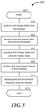
- Figure 5 is a block diagram of a method for providing a mediated-reality display for surgical visualization according to one embodiment of the present technology.
- the routine 600 begins in block 601.
- first image data is received from a first imager 113a
- second image data is received from a second imager 113b.
- the first imager 113a can be positioned over a user's right eye when wearing a head-mounted display assembly
- the second imager 113b can be positioned over the user's left eye when wearing the head-mounted display assembly 100.
- the routine 600 continues in block 607 with processing the first image data and the second image data.
- the processing can be performed by remote electronics (e.g., computing component 207) in wired or wireless communication with the head-mounted display assembly 100. Or in some embodiments, the processing can be performed via control electronics 115a-b carried by the assembly 100.
- the first processed image is displayed at a first display 119a
- a second processed image is displayed at a second display 119b.
- the first display 119a can be configured to display the first processed image to the user's right eye when wearing the assembly 100
- the second display 119b can be configured to display the second processed image to the user's left eye when wearing the assembly 100.
- the first and second processed images can be presented for stereoscopic effect, such that the user perceives a three-dimensional depth of field when viewing both processed images simultaneously.
- a mediated-reality visualization system including a head-mounted display assembly with an integrated display device and an integrated image capture device can be used in construction, manufacturing, the service industry, gaming, entertainment, and a variety of other contexts.
Landscapes
- Health & Medical Sciences (AREA)
- Life Sciences & Earth Sciences (AREA)
- Engineering & Computer Science (AREA)
- Surgery (AREA)
- Nuclear Medicine, Radiotherapy & Molecular Imaging (AREA)
- Medical Informatics (AREA)
- Biomedical Technology (AREA)
- Heart & Thoracic Surgery (AREA)
- Molecular Biology (AREA)
- Animal Behavior & Ethology (AREA)
- General Health & Medical Sciences (AREA)
- Public Health (AREA)
- Veterinary Medicine (AREA)
- Pathology (AREA)
- Physics & Mathematics (AREA)
- Radiology & Medical Imaging (AREA)
- Biophysics (AREA)
- Optics & Photonics (AREA)
- Signal Processing (AREA)
- Multimedia (AREA)
- Theoretical Computer Science (AREA)
- General Engineering & Computer Science (AREA)
- Oral & Maxillofacial Surgery (AREA)
- Human Computer Interaction (AREA)
- General Physics & Mathematics (AREA)
- Mechanical Engineering (AREA)
- Gynecology & Obstetrics (AREA)
- Robotics (AREA)
- Computing Systems (AREA)
- Testing, Inspecting, Measuring Of Stereoscopic Televisions And Televisions (AREA)
- Endoscopes (AREA)
- Closed-Circuit Television Systems (AREA)
- Stereoscopic And Panoramic Photography (AREA)
- Studio Devices (AREA)
Claims (15)
- Système de visualisation chirurgicale par réalité induite, comprenant :
un ensemble d'affichage au mécanisme monté sur la tête (100) comportant :une monture (103) configurée pour être portée sur la tête d'un utilisateur ;un dispositif de capture d'images (113a, 113b) couplé à la monture (103), le dispositif de capture d'images (113a, 113b) étant une caméra plénoptique intégrant un capteur d'images (405) et un réseau d'éléments capteurs (405a-d) correspondant à différentes parties du capteur d'images (405) qui reçoivent la lumière émise par différentes lentilles (407), chaque partie des éléments capteurs (405a-d) ayant un différent champ de vision ;un dispositif d'affichage (109) couplé à la monture (103), le dispositif d'affichage (109) étant configuré pour afficher une image en direction d'un œil de l'utilisateur ;un dispositif informatique (207) en communication avec le dispositif d'affichage (109) et le dispositif de capture d'images (113a, 113b), le dispositif informatique (207) étant configuré pour :recevoir des données d'image en provenance du dispositif de capture d'images (113a, 113b) ;définir un rendu avec une caméra virtuelle (409) ayant un positionnement et un champ de vision, et dans lequel seules des données d'une partie des éléments capteurs (405a-d) pour lesquelles le positionnement de la caméra virtuelle (409) se situe dans le champ de vision de la partie des éléments capteurs (405a-d), ou pour lesquelles le champ de vision de la partie des éléments capteurs (405a-d) se situe dans le champ de vision de la caméra virtuelle (409), sont utilisées pour définir un rendu d'image à partir de la caméra virtuelle (409), dans lequel il se peut que la caméra virtuelle (409) soit positionnée devant les éléments capteurs (405a-d), ou que la caméra virtuelle (409) soit positionnée derrière les éléments capteurs (405ad) ; etprésenter une image correspondant à la caméra virtuelle (409) à partir des données d'image sur le dispositif d'affichage (109). - Système de visualisation chirurgicale par réalité induite selon la revendication 1, dans lequel le dispositif informatique (207) est configuré de sorte à présenter l'image en temps réel.
- Système de visualisation chirurgicale par réalité induite selon la revendication 1, comprenant en outre au moins un second dispositif de capture d'images (203) situé à distance de l'ensemble d'affichage au mécanisme monté sur la tête (100), dans lequel le dispositif informatique (207) est en outre configuré de sorte à :
recevoir des données d'image supplémentaires en provenance du second dispositif de capture d'images (203) ; et présenter une image au moins en partie à partir des données d'images supplémentaires sur le dispositif d'affichage (109). - Système de visualisation chirurgicale par réalité induite selon la revendication 1, dans lequel le dispositif de capture d'images (113a, 113b) comprend au moins une caméra plénoptique.
- Système de visualisation chirurgicale par réalité induite selon l'une quelconque des revendications précédentes, dans lequel le dispositif informatique (207) est configuré pour définir un rendu avec au moins une caméra virtuelle (409) à un emplacement correspondant à un positionnement de l'œil d'un utilisateur lorsque ce dernier porte la monture.
- Système de visualisation chirurgicale par réalité induite selon l'une quelconque des revendications précédentes, dans lequel le rendu avec au moins une caméra virtuelle (409) comprend le rendu d'une vision élargie d'une partie d'un champ lumineux capturé.
- Système de visualisation chirurgicale par réalité induite selon l'une quelconque des revendications précédentes, dans lequel le positionnement de la caméra virtuelle (409) se situe devant les éléments capteurs (405a-d), et dans lequel seules des données des parties des éléments capteurs (405a-d), pour lesquelles le positionnement de la caméra virtuelle (409) se situe dans le champ de vision desdites parties des éléments capteurs (405a-d), sont utilisées pour définir un rendu d'image à partir de la caméra virtuelle (409).
- Système de visualisation chirurgicale par réalité induite selon l'une quelconque des revendications 1 à 6, dans lequel le positionnement de la caméra virtuelle (409) se situe derrière les éléments capteurs (405a-d), et dans lequel seules des données des parties des éléments capteurs (405a-d) pour lesquelles le champ de vision desdites parties des éléments capteurs (405a-d) se situe dans le champ de vision de la caméra virtuelle (409), sont utilisées pour définir un rendu d'image à partir de la caméra virtuelle (409).
- Procédé de visualisation chirurgicale par réalité induite, le procédé consistant à :fournir un afficheur au mécanisme monté sur la tête (100) comportant une monture (103) configurée pour être portée sur la tête d'un utilisateur, un premier et un second imageurs (113a, 113b) couplés à la monture (103), et un premier et un second afficheurs (119a, 119b) couplés à la monture (103) ;recevoir des premières données d'image en provenance du premier imageur (113a), qui est une caméra plénoptique intégrant un premier capteur d'images (405), et un réseau de premiers éléments capteurs (405a-d) correspondant à différentes parties du premier capteur d'images (405) qui reçoivent la lumière émise par différentes lentilles (407), chaque partie des premiers éléments capteurs (405a-d) ayant un différent champ de vision ;recevoir des secondes données d'image en provenance du second imageur (113b), qui est une caméra plénoptique intégrant un second capteur d'images (405), et un réseau de seconds éléments capteurs (405a-d) correspondant à différentes parties du second capteur d'images (405) qui reçoivent la lumière émise par différentes lentilles (407), chaque partie des seconds éléments capteurs (405a-d) ayant un différent champ de vision ;traiter les premières données d'image et les secondes données d'image ;définir un rendu avec une première caméra virtuelle (409) ayant un positionnement et un champ de vision, et dans lequel seules des données d'une partie des premiers éléments capteurs (405a-d) pour lesquelles le positionnement de la première caméra virtuelle (409) se situe dans le champ de vision de la partie des premiers éléments capteurs (405a-d), ou pour lesquelles le champ de vision de la partie des premiers éléments capteurs(405a-d) se situe dans le champ de vision de la première caméra virtuelle (409), sont utilisées pour définir un rendu d'image à partir de la première caméra virtuelle (409), dans lequel il se peut que la première caméra virtuelle (409) soit positionnée devant les éléments capteurs (405a-d), ou que la première caméra virtuelle (409) soit positionnée derrière les éléments capteurs (405a-d) ;afficher une image correspondant à la caméra virtuelle (409) à partir des premières données d'image traitées sur le premier afficheur (109) ;définir un rendu avec une seconde caméra virtuelle (409) ayant un positionnement et un champ de vision, et dans lequel seules des données d'une partie des seconds éléments capteurs (405a-d) pour lesquelles le positionnement de la seconde caméra virtuelle (409) se situe dans le champ de vision de la partie des seconds éléments capteurs (405a-d), ou pour lesquelles le champ de vision de la partie des seconds éléments capteurs(405a-d) se situe dans le champ de vision de la seconde caméra virtuelle (409), sont utilisées pour définir un rendu d'image à partir de la seconde caméra virtuelle (409), dans lequel il se peut que la seconde caméra virtuelle (409) soit positionnée devant les éléments capteurs (405a-d), ou que la seconde caméra virtuelle (409) soit positionnée derrière les éléments capteurs (405a-d) ; etafficher une image correspondant à la seconde caméra virtuelle (409) à partir des secondes données d'image traitées sur le second afficheur (109).
- Procédé selon la revendication 9, dans lequel les premières et les secondes données d'image traitées sont affichées sur le premier et le second afficheurs (119a, 110b) en temps réel.
- Procédé selon la revendication 9, consistant à :recevoir des troisièmes données d'image ;traiter les troisièmes données d'image ; etafficher les troisièmes données traitées sur le premier afficheur (119a) et/ou sur le second afficheur (119b).
- Procédé selon la revendication 11, dans lequel les troisièmes données d'image comprennent au moins : des données d'image de fluorescence, des données obtenues par imagerie par résonance magnétique, des données d'image de tomographies assistée par ordinateur, des données d'une image à rayons x, des données de diagramme anatomique, ou des données sur les signes vitaux.
- Procédé selon la revendication 11, dans lequel les troisièmes données d'image proviennent d'un troisième imageur (203) situé à distance de l'afficheur au mécanisme monté sur la tête (100).
- Procédé selon la revendication 9, consistant en outre à suivre le mouvement de l'afficheur au mécanisme monté sur la tête (100).
- Procédé selon la revendication 9, dans lequel le rendu avec la première et la seconde caméras virtuelles (409) comprend le rendu avec la première et la seconde caméras virtuelles à des emplacements correspondant à un positionnement des yeux de l'utilisateur lorsque l'afficheur (100) est monté sur la tête de l'utilisateur.
Applications Claiming Priority (2)
| Application Number | Priority Date | Filing Date | Title |
|---|---|---|---|
| US201462000900P | 2014-05-20 | 2014-05-20 | |
| PCT/US2015/031637 WO2015179446A1 (fr) | 2014-05-20 | 2015-05-19 | Systèmes et procédés de visualisation chirurgicale par réalité induite |
Publications (3)
| Publication Number | Publication Date |
|---|---|
| EP3146715A1 EP3146715A1 (fr) | 2017-03-29 |
| EP3146715A4 EP3146715A4 (fr) | 2018-01-10 |
| EP3146715B1 true EP3146715B1 (fr) | 2022-03-23 |
Family
ID=54554655
Family Applications (1)
| Application Number | Title | Priority Date | Filing Date |
|---|---|---|---|
| EP15795790.3A Active EP3146715B1 (fr) | 2014-05-20 | 2015-05-19 | Systèmes et procédés de visualisation chirurgicale par réalité induite |
Country Status (5)
| Country | Link |
|---|---|
| US (3) | US20170099479A1 (fr) |
| EP (1) | EP3146715B1 (fr) |
| JP (1) | JP2017524281A (fr) |
| CA (1) | CA2949241A1 (fr) |
| WO (1) | WO2015179446A1 (fr) |
Families Citing this family (131)
| Publication number | Priority date | Publication date | Assignee | Title |
|---|---|---|---|---|
| WO2008017051A2 (fr) | 2006-08-02 | 2008-02-07 | Inneroptic Technology Inc. | Système et procédé d'imagerie dynamique en temps réel sur un site d'intervention médicale et utilisant des modalités multiples |
| US8641621B2 (en) | 2009-02-17 | 2014-02-04 | Inneroptic Technology, Inc. | Systems, methods, apparatuses, and computer-readable media for image management in image-guided medical procedures |
| US11464578B2 (en) | 2009-02-17 | 2022-10-11 | Inneroptic Technology, Inc. | Systems, methods, apparatuses, and computer-readable media for image management in image-guided medical procedures |
| US8690776B2 (en) | 2009-02-17 | 2014-04-08 | Inneroptic Technology, Inc. | Systems, methods, apparatuses, and computer-readable media for image guided surgery |
| US11450113B1 (en) | 2009-06-04 | 2022-09-20 | Masoud Vaziri | Method and apparatus for a wearable computer |
| US10064552B1 (en) * | 2009-06-04 | 2018-09-04 | Masoud Vaziri | Method and apparatus for a compact and high resolution mind-view communicator |
| US8872910B1 (en) | 2009-06-04 | 2014-10-28 | Masoud Vaziri | Method and apparatus for a compact and high resolution eye-view recorder |
| US11547499B2 (en) | 2014-04-04 | 2023-01-10 | Surgical Theater, Inc. | Dynamic and interactive navigation in a surgical environment |
| JP6574939B2 (ja) * | 2014-09-16 | 2019-09-18 | ソニー株式会社 | 表示制御装置、表示制御方法、表示制御システムおよび頭部装着ディスプレイ |
| US9901406B2 (en) | 2014-10-02 | 2018-02-27 | Inneroptic Technology, Inc. | Affected region display associated with a medical device |
| US10188467B2 (en) | 2014-12-12 | 2019-01-29 | Inneroptic Technology, Inc. | Surgical guidance intersection display |
| US10013808B2 (en) | 2015-02-03 | 2018-07-03 | Globus Medical, Inc. | Surgeon head-mounted display apparatuses |
| US10473942B2 (en) * | 2015-06-05 | 2019-11-12 | Marc Lemchen | Apparatus and method for image capture of medical or dental images using a head mounted camera and computer system |
| DE102015219859B4 (de) * | 2015-10-13 | 2017-07-27 | Carl Zeiss Vision International Gmbh | Vorrichtung und Verfahren für die AR-Darstellung |
| BR112018007473A2 (pt) | 2015-10-14 | 2018-10-23 | Surgical Theater LLC | navegação cirúrgica de realidade aumentada |
| EP3165153A1 (fr) * | 2015-11-05 | 2017-05-10 | Deutsches Krebsforschungszentrum Stiftung des Öffentlichen Rechts | Système de chirurgie assistée par fluorescence |
| US9675319B1 (en) | 2016-02-17 | 2017-06-13 | Inneroptic Technology, Inc. | Loupe display |
| US12444141B2 (en) | 2016-09-16 | 2025-10-14 | Zimmer, Inc. | Augmented reality surgical technique guidance |
| US10278778B2 (en) | 2016-10-27 | 2019-05-07 | Inneroptic Technology, Inc. | Medical device navigation using a virtual 3D space |
| EP3545675A4 (fr) * | 2016-11-24 | 2020-07-01 | The University of Washington | Capture et restitution de champ lumineux pour des visiocasques |
| US10918445B2 (en) * | 2016-12-19 | 2021-02-16 | Ethicon Llc | Surgical system with augmented reality display |
| US10806334B2 (en) * | 2017-02-28 | 2020-10-20 | Verily Life Sciences Llc | System and method for multiclass classification of images using a programmable light source |
| CN116236282B (zh) * | 2017-05-05 | 2026-06-16 | 史赛克欧洲运营有限公司 | 手术导航系统 |
| US10973391B1 (en) | 2017-05-22 | 2021-04-13 | James X. Liu | Mixed reality viewing of a surgical procedure |
| CA3006939A1 (fr) * | 2017-06-01 | 2018-12-01 | Monroe Solutions Group Inc. | Systemes et methodes d'etablissement de la telepresence d'un utilisateur distant |
| US10877262B1 (en) * | 2017-06-21 | 2020-12-29 | Itzhak Luxembourg | Magnification glasses with multiple cameras |
| US11813118B2 (en) | 2017-07-10 | 2023-11-14 | University Of Kentucky Research Foundation | Loupe-based intraoperative fluorescence imaging device for the guidance of tumor resection |
| US11259879B2 (en) | 2017-08-01 | 2022-03-01 | Inneroptic Technology, Inc. | Selective transparency to assist medical device navigation |
| US11432877B2 (en) * | 2017-08-02 | 2022-09-06 | Medtech S.A. | Surgical field camera system that only uses images from cameras with an unobstructed sight line for tracking |
| US10987016B2 (en) * | 2017-08-23 | 2021-04-27 | The Boeing Company | Visualization system for deep brain stimulation |
| US10564111B2 (en) * | 2017-08-23 | 2020-02-18 | The Boeing Company | Borescope for generating an image with adjustable depth of field and associated inspection system and method |
| US10861236B2 (en) | 2017-09-08 | 2020-12-08 | Surgical Theater, Inc. | Dual mode augmented reality surgical system and method |
| EP3684463B1 (fr) | 2017-09-19 | 2025-05-14 | Neuroenhancement Lab, LLC | Procédé et appareil de neuro-activation |
| US10930709B2 (en) | 2017-10-03 | 2021-02-23 | Lockheed Martin Corporation | Stacked transparent pixel structures for image sensors |
| US11310481B2 (en) * | 2017-10-26 | 2022-04-19 | Sony Corporation | Imaging device, system, method and program for converting a first image into a plurality of second images |
| US10510812B2 (en) | 2017-11-09 | 2019-12-17 | Lockheed Martin Corporation | Display-integrated infrared emitter and sensor structures |
| US10772488B2 (en) * | 2017-11-10 | 2020-09-15 | Endoluxe Inc. | System and methods for endoscopic imaging |
| CN107811706B (zh) * | 2017-11-27 | 2019-02-26 | 东北大学 | 一种基于传像光纤的手术导航系统 |
| US11717686B2 (en) | 2017-12-04 | 2023-08-08 | Neuroenhancement Lab, LLC | Method and apparatus for neuroenhancement to facilitate learning and performance |
| JP6369706B1 (ja) * | 2017-12-27 | 2018-08-08 | 株式会社Medi Plus | 医療動画処理システム |
| US12280219B2 (en) | 2017-12-31 | 2025-04-22 | NeuroLight, Inc. | Method and apparatus for neuroenhancement to enhance emotional response |
| US11318277B2 (en) | 2017-12-31 | 2022-05-03 | Neuroenhancement Lab, LLC | Method and apparatus for neuroenhancement to enhance emotional response |
| US11484365B2 (en) | 2018-01-23 | 2022-11-01 | Inneroptic Technology, Inc. | Medical image guidance |
| US10838250B2 (en) | 2018-02-07 | 2020-11-17 | Lockheed Martin Corporation | Display assemblies with electronically emulated transparency |
| US10594951B2 (en) | 2018-02-07 | 2020-03-17 | Lockheed Martin Corporation | Distributed multi-aperture camera array |
| US10979699B2 (en) | 2018-02-07 | 2021-04-13 | Lockheed Martin Corporation | Plenoptic cellular imaging system |
| US10652529B2 (en) | 2018-02-07 | 2020-05-12 | Lockheed Martin Corporation | In-layer Signal processing |
| US10690910B2 (en) | 2018-02-07 | 2020-06-23 | Lockheed Martin Corporation | Plenoptic cellular vision correction |
| US11616941B2 (en) | 2018-02-07 | 2023-03-28 | Lockheed Martin Corporation | Direct camera-to-display system |
| US10951883B2 (en) | 2018-02-07 | 2021-03-16 | Lockheed Martin Corporation | Distributed multi-screen array for high density display |
| US20190254753A1 (en) | 2018-02-19 | 2019-08-22 | Globus Medical, Inc. | Augmented reality navigation systems for use with robotic surgical systems and methods of their use |
| KR102046351B1 (ko) * | 2018-03-12 | 2019-12-02 | 한국기계연구원 | 증강현실을 이용한 착용형 로봇 제어시스템 및 이를 이용한 착용형 로봇 제어방법 |
| US11364361B2 (en) | 2018-04-20 | 2022-06-21 | Neuroenhancement Lab, LLC | System and method for inducing sleep by transplanting mental states |
| US11666411B2 (en) * | 2018-05-10 | 2023-06-06 | Memorial Sloan Kettering Cancer Center | Systems for augmented reality surgical and clinical visualization |
| US10667366B2 (en) * | 2018-06-29 | 2020-05-26 | Osram Sylvania Inc. | Lighting devices with automatic lighting adjustment |
| US10895757B2 (en) | 2018-07-03 | 2021-01-19 | Verb Surgical Inc. | Systems and methods for three-dimensional visualization during robotic surgery |
| US11308591B1 (en) | 2018-07-11 | 2022-04-19 | Masoud Vaziri | Method and apparatus for a software enabled high resolution ultrasound imaging device |
| US12181579B2 (en) | 2018-07-16 | 2024-12-31 | Cilag GmbH Intemational | Controlling an emitter assembly pulse sequence |
| JP2020016869A (ja) * | 2018-07-27 | 2020-01-30 | 伸也 佐藤 | デジタル式望遠メガネ |
| US11030724B2 (en) | 2018-09-13 | 2021-06-08 | Samsung Electronics Co., Ltd. | Method and apparatus for restoring image |
| US11452839B2 (en) | 2018-09-14 | 2022-09-27 | Neuroenhancement Lab, LLC | System and method of improving sleep |
| US10623660B1 (en) * | 2018-09-27 | 2020-04-14 | Eloupes, Inc. | Camera array for a mediated-reality system |
| WO2020069420A2 (fr) | 2018-09-28 | 2020-04-02 | Ocelot Laboratories Llc | Système de caméra |
| US12008721B2 (en) * | 2018-10-26 | 2024-06-11 | Intuitive Surgical Operations, Inc. | Mixed reality systems and methods for indicating an extent of a field of view of an imaging device |
| EP4318401A3 (fr) | 2018-10-26 | 2024-05-08 | Intuitive Surgical Operations, Inc. | Systèmes et procédés de réalité mixte pour indiquer une étendue d'un champ de vision d'un dispositif d'imagerie |
| USRE50624E1 (en) | 2018-11-19 | 2025-10-07 | Optics Innovation Llc | Method and apparatus for super resolution imaging and eye tracking devices |
| US10866413B2 (en) | 2018-12-03 | 2020-12-15 | Lockheed Martin Corporation | Eccentric incident luminance pupil tracking |
| EP3897346A4 (fr) | 2019-01-23 | 2022-09-28 | Proprio, Inc. | Alignement d'images de balayage préopératoires avec des images opératoires en temps réel pour une vue de réalité médiée d'un site chirurgical |
| US12471994B2 (en) | 2019-01-31 | 2025-11-18 | Intuitive Surgical Operations, Inc. | Systems and methods for facilitating insertion of a surgical instrument into a surgical space |
| US11857378B1 (en) * | 2019-02-14 | 2024-01-02 | Onpoint Medical, Inc. | Systems for adjusting and tracking head mounted displays during surgery including with surgical helmets |
| US12257013B2 (en) | 2019-03-15 | 2025-03-25 | Cilag Gmbh International | Robotic surgical systems with mechanisms for scaling camera magnification according to proximity of surgical tool to tissue |
| US10698201B1 (en) | 2019-04-02 | 2020-06-30 | Lockheed Martin Corporation | Plenoptic cellular axis redirection |
| US11786694B2 (en) | 2019-05-24 | 2023-10-17 | NeuroLight, Inc. | Device, method, and app for facilitating sleep |
| US11029755B2 (en) | 2019-08-30 | 2021-06-08 | Shopify Inc. | Using prediction information with light fields |
| US11430175B2 (en) | 2019-08-30 | 2022-08-30 | Shopify Inc. | Virtual object areas using light fields |
| GB2588774B (en) * | 2019-11-05 | 2024-05-15 | Arspectra Sarl | Augmented reality headset for medical imaging |
| US11992373B2 (en) | 2019-12-10 | 2024-05-28 | Globus Medical, Inc | Augmented reality headset with varied opacity for navigated robotic surgery |
| US12220176B2 (en) | 2019-12-10 | 2025-02-11 | Globus Medical, Inc. | Extended reality instrument interaction zone for navigated robotic |
| US12133772B2 (en) | 2019-12-10 | 2024-11-05 | Globus Medical, Inc. | Augmented reality headset for navigated robotic surgery |
| US12364568B2 (en) * | 2019-12-13 | 2025-07-22 | Smith & Nephew, Inc. | Anatomical feature extraction and presentation using augmented reality |
| US11896442B2 (en) | 2019-12-30 | 2024-02-13 | Cilag Gmbh International | Surgical systems for proposing and corroborating organ portion removals |
| US12207881B2 (en) | 2019-12-30 | 2025-01-28 | Cilag Gmbh International | Surgical systems correlating visualization data and powered surgical instrument data |
| US11744667B2 (en) | 2019-12-30 | 2023-09-05 | Cilag Gmbh International | Adaptive visualization by a surgical system |
| US11284963B2 (en) | 2019-12-30 | 2022-03-29 | Cilag Gmbh International | Method of using imaging devices in surgery |
| US12053223B2 (en) | 2019-12-30 | 2024-08-06 | Cilag Gmbh International | Adaptive surgical system control according to surgical smoke particulate characteristics |
| US11776144B2 (en) | 2019-12-30 | 2023-10-03 | Cilag Gmbh International | System and method for determining, adjusting, and managing resection margin about a subject tissue |
| US12453592B2 (en) | 2019-12-30 | 2025-10-28 | Cilag Gmbh International | Adaptive surgical system control according to surgical smoke cloud characteristics |
| US11759283B2 (en) | 2019-12-30 | 2023-09-19 | Cilag Gmbh International | Surgical systems for generating three dimensional constructs of anatomical organs and coupling identified anatomical structures thereto |
| US12002571B2 (en) | 2019-12-30 | 2024-06-04 | Cilag Gmbh International | Dynamic surgical visualization systems |
| US11832996B2 (en) | 2019-12-30 | 2023-12-05 | Cilag Gmbh International | Analyzing surgical trends by a surgical system |
| EP3851896B1 (fr) * | 2020-01-20 | 2026-03-04 | Leica Instruments (Singapore) Pte. Ltd. | Appareils, procédés et programmes d'ordinateur pour commander un système de microscope |
| WO2021150921A1 (fr) | 2020-01-22 | 2021-07-29 | Photonic Medical Inc | Loupe numérique étalonnée, multimodale, à vision ouverte avec détection de profondeur |
| JP7358258B2 (ja) | 2020-01-28 | 2023-10-10 | キヤノン株式会社 | 画像観察装置 |
| US11464581B2 (en) | 2020-01-28 | 2022-10-11 | Globus Medical, Inc. | Pose measurement chaining for extended reality surgical navigation in visible and near infrared spectrums |
| US11382699B2 (en) | 2020-02-10 | 2022-07-12 | Globus Medical Inc. | Extended reality visualization of optical tool tracking volume for computer assisted navigation in surgery |
| US11207150B2 (en) | 2020-02-19 | 2021-12-28 | Globus Medical, Inc. | Displaying a virtual model of a planned instrument attachment to ensure correct selection of physical instrument attachment |
| US11607277B2 (en) | 2020-04-29 | 2023-03-21 | Globus Medical, Inc. | Registration of surgical tool with reference array tracked by cameras of an extended reality headset for assisted navigation during surgery |
| US11510750B2 (en) | 2020-05-08 | 2022-11-29 | Globus Medical, Inc. | Leveraging two-dimensional digital imaging and communication in medicine imagery in three-dimensional extended reality applications |
| US11153555B1 (en) | 2020-05-08 | 2021-10-19 | Globus Medical Inc. | Extended reality headset camera system for computer assisted navigation in surgery |
| US11382700B2 (en) | 2020-05-08 | 2022-07-12 | Globus Medical Inc. | Extended reality headset tool tracking and control |
| US10949986B1 (en) | 2020-05-12 | 2021-03-16 | Proprio, Inc. | Methods and systems for imaging a scene, such as a medical scene, and tracking objects within the scene |
| US11087557B1 (en) | 2020-06-03 | 2021-08-10 | Tovy Kamine | Methods and systems for remote augmented reality communication for guided surgery |
| US11737831B2 (en) | 2020-09-02 | 2023-08-29 | Globus Medical Inc. | Surgical object tracking template generation for computer assisted navigation during surgical procedure |
| US12034904B2 (en) | 2020-09-23 | 2024-07-09 | Proprio, Inc. | Endoscopic imaging systems for generating three dimensional images, and associated systems and methods |
| US12023106B2 (en) * | 2020-10-12 | 2024-07-02 | Johnson & Johnson Surgical Vision, Inc. | Virtual reality 3D eye-inspection by combining images from position-tracked optical visualization modalities |
| US12045957B2 (en) | 2020-10-21 | 2024-07-23 | Johnson & Johnson Surgical Vision, Inc. | Visualizing an organ using multiple imaging modalities combined and displayed in virtual reality |
| FR3116135B1 (fr) * | 2020-11-10 | 2023-12-08 | Inst Mines Telecom | Système de capture et du suivi du champ visuel attentionnel et/ou du pilotage du regard d’un individu et/ou la désignation visuelle de cibles. |
| DE102020214824B4 (de) * | 2020-11-25 | 2025-03-20 | Carl Zeiss Meditec Ag | Verfahren zum Betreiben eines Visualisierungssystems bei einer chirurgischen Anwendung und Visualisierungssystem für eine chirurgische Anwendung |
| CN114637391B (zh) * | 2020-11-30 | 2025-08-29 | 华为技术有限公司 | 基于光场的vr内容处理方法及设备 |
| EP4013048A1 (fr) * | 2020-12-08 | 2022-06-15 | Koninklijke Philips N.V. | Visualisation d'objet |
| US11295460B1 (en) | 2021-01-04 | 2022-04-05 | Proprio, Inc. | Methods and systems for registering preoperative image data to intraoperative image data of a scene, such as a surgical scene |
| EP4030219B1 (fr) * | 2021-01-13 | 2025-07-30 | BHS Technologies GmbH | Système d'imagerie médicale et procédé de commande d'un tel système d'imagerie |
| CN112890744A (zh) * | 2021-01-25 | 2021-06-04 | 汉斯夫(杭州)医学科技有限公司 | 头戴式放大镜面罩 |
| CN114882976A (zh) * | 2021-02-05 | 2022-08-09 | 中强光电股份有限公司 | 医疗用影像辅助系统及医疗用影像辅助方法 |
| WO2022176199A1 (fr) * | 2021-02-22 | 2022-08-25 | オリンパス株式会社 | Système chirurgical et procédé de commande de système chirurgical |
| JP2022142763A (ja) * | 2021-03-16 | 2022-09-30 | ロレックス・ソシエテ・アノニム | 時計職人用ルーペ |
| JP2024516547A (ja) * | 2021-04-14 | 2024-04-16 | サーキヌス メディカル テクノロジー エルエルシー | Lidarベースの解剖学的マッピングに係るシステム及び方法 |
| US12052484B2 (en) | 2021-04-27 | 2024-07-30 | Apple Inc. | Camera integration for portable electronic devices |
| WO2023021451A1 (fr) | 2021-08-18 | 2023-02-23 | Augmedics Ltd. | Assistance par réalité augmentée pour ostéotomie et discectomie |
| CN113520619A (zh) * | 2021-08-26 | 2021-10-22 | 重庆市妇幼保健院 | 用于三维医疗影像系统与双目视觉系统配准的标记元件及其装配方法 |
| US12261988B2 (en) * | 2021-11-08 | 2025-03-25 | Proprio, Inc. | Methods for generating stereoscopic views in multicamera systems, and associated devices and systems |
| US12376731B2 (en) | 2022-01-10 | 2025-08-05 | Endoluxe Inc. | Systems, apparatuses, and methods for endoscopy |
| WO2023177785A1 (fr) | 2022-03-17 | 2023-09-21 | Mako Surgical Corp. | Techniques pour fixer ensemble des composants d'un ou de plusieurs chariots chirurgicaux |
| WO2023203521A1 (fr) | 2022-04-21 | 2023-10-26 | Augmedics Ltd. | Systèmes et procédés de visualisation d'image médicale |
| US12003709B1 (en) * | 2022-11-16 | 2024-06-04 | International Business Machines Corporation | Visual data transmission by an air-gapped system |
| WO2025231486A1 (fr) * | 2024-05-03 | 2025-11-06 | Rutgers, The State University Of New Jersey | Système de prévention de lésion d'une lumière corporelle |
| US12608041B2 (en) | 2024-07-30 | 2026-04-21 | Dell Products L.P. | Facilitating visual intent using a display free body wearable computing device |
| US12556802B2 (en) * | 2024-07-30 | 2026-02-17 | Dell Products L.P. | Image capturing using a display free body wearable computing device |
| US12541881B1 (en) | 2024-07-30 | 2026-02-03 | Dell Products L.P. | Managing operation of a display free body wearable computing device |
| US12699420B2 (en) | 2024-07-30 | 2026-08-04 | Dell Products L.P. | Body wearable computing device |
| US12452401B1 (en) * | 2024-09-19 | 2025-10-21 | Tru Simulation + Training | System and method for measuring viewpoint fidelity in head mounted display |
Citations (1)
| Publication number | Priority date | Publication date | Assignee | Title |
|---|---|---|---|---|
| US20070121423A1 (en) * | 2001-12-20 | 2007-05-31 | Daniel Rioux | Head-mounted display apparatus for profiling system |
Family Cites Families (20)
| Publication number | Priority date | Publication date | Assignee | Title |
|---|---|---|---|---|
| JP2001522063A (ja) * | 1997-10-30 | 2001-11-13 | ザ マイクロオプティカル コーポレイション | 眼鏡インターフェースシステム |
| WO2001005161A1 (fr) * | 1999-07-13 | 2001-01-18 | Surgivision Ltd. | Observation video stereoscopique et systeme de grossissement d'image |
| JP2004538538A (ja) * | 2000-10-05 | 2004-12-24 | シーメンス コーポレイト リサーチ インコーポレイテツド | 強化現実可視化付きの、手術中にイメージガイドされる神経外科手術法及び手術用装置 |
| JP2002157606A (ja) * | 2000-11-17 | 2002-05-31 | Canon Inc | 画像表示制御装置、複合現実感提示システム、画像表示制御方法、及び処理プログラムを提供する媒体 |
| JP2002207832A (ja) * | 2000-12-28 | 2002-07-26 | Atsushi Takahashi | インターネット技術指導教育配信システム、及び通信網を利用した指導システム |
| AU2002361572A1 (en) * | 2001-10-19 | 2003-04-28 | University Of North Carolina At Chape Hill | Methods and systems for dynamic virtual convergence and head mountable display |
| ES2239099T3 (es) * | 2001-11-27 | 2005-09-16 | Freni Brembo S.P.A. | Dispositivo de ajuste de zapatas interiores de freno de tambor de doble servo. |
| US7411611B2 (en) * | 2003-08-25 | 2008-08-12 | Barco N. V. | Device and method for performing multiple view imaging by means of a plurality of video processing devices |
| US7774044B2 (en) * | 2004-02-17 | 2010-08-10 | Siemens Medical Solutions Usa, Inc. | System and method for augmented reality navigation in a medical intervention procedure |
| US20050185711A1 (en) * | 2004-02-20 | 2005-08-25 | Hanspeter Pfister | 3D television system and method |
| KR100819819B1 (ko) * | 2004-03-26 | 2008-04-08 | 아츠시 타카하시 | 삼차원 시각 지시 기능을 갖춘 삼차원 실체 디지털 확대경 시스템 및 삼차원 실체 디지털 확대경 시스템을 위한 삼차원 시각 지시 방법 |
| JP4717728B2 (ja) * | 2005-08-29 | 2011-07-06 | キヤノン株式会社 | ステレオ表示装置及びその制御方法 |
| US20070236514A1 (en) * | 2006-03-29 | 2007-10-11 | Bracco Imaging Spa | Methods and Apparatuses for Stereoscopic Image Guided Surgical Navigation |
| EP2244484B1 (fr) * | 2009-04-22 | 2012-03-28 | Raytrix GmbH | Procédé d'imagerie numérique pour synthétiser une image utilisant des données enregistrées avec une caméra plénoptique |
| JP2011248723A (ja) * | 2010-05-28 | 2011-12-08 | Sony Corp | 画像処理装置および方法、並びにプログラム |
| WO2012065163A2 (fr) * | 2010-11-12 | 2012-05-18 | Emory University | Systèmes et procédés additionnels fournissant une assistance anatomique en temps réel lors d'une procédure diagnostique ou thérapeutique |
| US8704882B2 (en) * | 2011-11-18 | 2014-04-22 | L-3 Communications Corporation | Simulated head mounted display system and method |
| KR20130112541A (ko) * | 2012-04-04 | 2013-10-14 | 삼성전자주식회사 | 플레놉틱 카메라 장치 |
| IL221863A (en) * | 2012-09-10 | 2014-01-30 | Elbit Systems Ltd | Digital video photography system when analyzing and displaying |
| US10664903B1 (en) * | 2017-04-27 | 2020-05-26 | Amazon Technologies, Inc. | Assessing clothing style and fit using 3D models of customers |
-
2015
- 2015-05-19 EP EP15795790.3A patent/EP3146715B1/fr active Active
- 2015-05-19 JP JP2016568921A patent/JP2017524281A/ja active Pending
- 2015-05-19 CA CA2949241A patent/CA2949241A1/fr not_active Abandoned
- 2015-05-19 US US15/311,138 patent/US20170099479A1/en not_active Abandoned
- 2015-05-19 WO PCT/US2015/031637 patent/WO2015179446A1/fr not_active Ceased
-
2019
- 2019-04-24 US US16/393,624 patent/US20200059640A1/en not_active Abandoned
-
2023
- 2023-04-13 US US18/300,097 patent/US20240080433A1/en not_active Abandoned
Patent Citations (1)
| Publication number | Priority date | Publication date | Assignee | Title |
|---|---|---|---|---|
| US20070121423A1 (en) * | 2001-12-20 | 2007-05-31 | Daniel Rioux | Head-mounted display apparatus for profiling system |
Also Published As
| Publication number | Publication date |
|---|---|
| US20240080433A1 (en) | 2024-03-07 |
| EP3146715A1 (fr) | 2017-03-29 |
| WO2015179446A1 (fr) | 2015-11-26 |
| EP3146715A4 (fr) | 2018-01-10 |
| CA2949241A1 (fr) | 2015-11-26 |
| US20170099479A1 (en) | 2017-04-06 |
| US20200059640A1 (en) | 2020-02-20 |
| JP2017524281A (ja) | 2017-08-24 |
Similar Documents
| Publication | Publication Date | Title |
|---|---|---|
| US20240080433A1 (en) | Systems and methods for mediated-reality surgical visualization | |
| US20230255446A1 (en) | Surgical visualization systems and displays | |
| US20230122367A1 (en) | Surgical visualization systems and displays | |
| US12178403B2 (en) | Light field capture and rendering for head-mounted displays | |
| US12219228B2 (en) | Stereoscopic visualization camera and integrated robotics platform | |
| EP2903551B1 (fr) | Système numérique pour la capture et l'affichage d'une vidéo chirurgicale | |
| US20220054223A1 (en) | Surgical visualization systems and displays | |
| US11154378B2 (en) | Surgical visualization systems and displays | |
| AU2024219905A1 (en) | Stereoscopic visualization camera and integrated robotics platform | |
| CN106796344B (zh) | 锁定在感兴趣对象上的放大图像的系统、布置和方法 | |
| US9766441B2 (en) | Surgical stereo vision systems and methods for microsurgery | |
| US9330477B2 (en) | Surgical stereo vision systems and methods for microsurgery | |
| US20060176242A1 (en) | Augmented reality device and method | |
| US11094283B2 (en) | Head-wearable presentation apparatus, method for operating the same, and medical-optical observation system |
Legal Events
| Date | Code | Title | Description |
|---|---|---|---|
| STAA | Information on the status of an ep patent application or granted ep patent |
Free format text: STATUS: THE INTERNATIONAL PUBLICATION HAS BEEN MADE |
|
| PUAI | Public reference made under article 153(3) epc to a published international application that has entered the european phase |
Free format text: ORIGINAL CODE: 0009012 |
|
| STAA | Information on the status of an ep patent application or granted ep patent |
Free format text: STATUS: REQUEST FOR EXAMINATION WAS MADE |
|
| 17P | Request for examination filed |
Effective date: 20161111 |
|
| AK | Designated contracting states |
Kind code of ref document: A1 Designated state(s): AL AT BE BG CH CY CZ DE DK EE ES FI FR GB GR HR HU IE IS IT LI LT LU LV MC MK MT NL NO PL PT RO RS SE SI SK SM TR |
|
| AX | Request for extension of the european patent |
Extension state: BA ME |
|
| DAV | Request for validation of the european patent (deleted) | ||
| DAX | Request for extension of the european patent (deleted) | ||
| A4 | Supplementary search report drawn up and despatched |
Effective date: 20171208 |
|
| RIC1 | Information provided on ipc code assigned before grant |
Ipc: G06F 3/01 20060101ALI20171204BHEP Ipc: G06F 3/14 20060101ALI20171204BHEP Ipc: H04N 13/04 00000000ALI20171204BHEP Ipc: A61B 1/00 20060101ALI20171204BHEP Ipc: H04N 13/02 00000000ALI20171204BHEP Ipc: A61B 90/00 20160101ALI20171204BHEP Ipc: H04N 13/00 20180101AFI20171204BHEP |
|
| RIN1 | Information on inventor provided before grant (corrected) |
Inventor name: SMITH, JOSHUA R. Inventor name: NICOLL, RUFUS GRIFFIN Inventor name: BROWD, SAMUEL R. |
|
| RIC1 | Information provided on ipc code assigned before grant |
Ipc: A61B 90/00 20160101ALI20171204BHEP Ipc: H04N 13/00 20180101AFI20171204BHEP Ipc: G06F 3/14 20060101ALI20171204BHEP Ipc: A61B 1/00 20060101ALI20171204BHEP Ipc: H04N 13/04 20060101ALI20171204BHEP Ipc: H04N 13/02 20060101ALI20171204BHEP Ipc: G06F 3/01 20060101ALI20171204BHEP |
|
| STAA | Information on the status of an ep patent application or granted ep patent |
Free format text: STATUS: EXAMINATION IS IN PROGRESS |
|
| 17Q | First examination report despatched |
Effective date: 20191212 |
|
| REG | Reference to a national code |
Ref country code: DE Ref legal event code: R079 Ref document number: 602015077737 Country of ref document: DE Free format text: PREVIOUS MAIN CLASS: H04N0013000000 Ipc: G06F0003010000 |
|
| GRAP | Despatch of communication of intention to grant a patent |
Free format text: ORIGINAL CODE: EPIDOSNIGR1 |
|
| STAA | Information on the status of an ep patent application or granted ep patent |
Free format text: STATUS: GRANT OF PATENT IS INTENDED |
|
| INTG | Intention to grant announced |
Effective date: 20201023 |
|
| RIC1 | Information provided on ipc code assigned before grant |
Ipc: H04N 5/225 20060101ALI20201009BHEP Ipc: A61B 90/30 20160101ALI20201009BHEP Ipc: H04N 13/239 20180101ALI20201009BHEP Ipc: H04N 13/111 20180101ALI20201009BHEP Ipc: A61B 1/045 20060101ALI20201009BHEP Ipc: H04N 13/156 20180101ALI20201009BHEP Ipc: A61B 34/20 20160101ALI20201009BHEP Ipc: G06F 3/01 20060101AFI20201009BHEP Ipc: A61B 1/00 20060101ALI20201009BHEP Ipc: A61B 1/05 20060101ALI20201009BHEP Ipc: H04N 13/344 20180101ALI20201009BHEP |
|
| GRAJ | Information related to disapproval of communication of intention to grant by the applicant or resumption of examination proceedings by the epo deleted |
Free format text: ORIGINAL CODE: EPIDOSDIGR1 |
|
| STAA | Information on the status of an ep patent application or granted ep patent |
Free format text: STATUS: EXAMINATION IS IN PROGRESS |
|
| INTC | Intention to grant announced (deleted) | ||
| GRAP | Despatch of communication of intention to grant a patent |
Free format text: ORIGINAL CODE: EPIDOSNIGR1 |
|
| STAA | Information on the status of an ep patent application or granted ep patent |
Free format text: STATUS: GRANT OF PATENT IS INTENDED |
|
| INTG | Intention to grant announced |
Effective date: 20211215 |
|
| GRAS | Grant fee paid |
Free format text: ORIGINAL CODE: EPIDOSNIGR3 |
|
| GRAA | (expected) grant |
Free format text: ORIGINAL CODE: 0009210 |
|
| STAA | Information on the status of an ep patent application or granted ep patent |
Free format text: STATUS: THE PATENT HAS BEEN GRANTED |
|
| AK | Designated contracting states |
Kind code of ref document: B1 Designated state(s): AL AT BE BG CH CY CZ DE DK EE ES FI FR GB GR HR HU IE IS IT LI LT LU LV MC MK MT NL NO PL PT RO RS SE SI SK SM TR |
|
| REG | Reference to a national code |
Ref country code: GB Ref legal event code: FG4D |
|
| REG | Reference to a national code |
Ref country code: CH Ref legal event code: EP |
|
| REG | Reference to a national code |
Ref country code: DE Ref legal event code: R096 Ref document number: 602015077737 Country of ref document: DE |
|
| REG | Reference to a national code |
Ref country code: IE Ref legal event code: FG4D |
|
| REG | Reference to a national code |
Ref country code: AT Ref legal event code: REF Ref document number: 1477906 Country of ref document: AT Kind code of ref document: T Effective date: 20220415 |
|
| REG | Reference to a national code |
Ref country code: LT Ref legal event code: MG9D |
|
| REG | Reference to a national code |
Ref country code: NL Ref legal event code: MP Effective date: 20220323 |
|
| PG25 | Lapsed in a contracting state [announced via postgrant information from national office to epo] |
Ref country code: SE Free format text: LAPSE BECAUSE OF FAILURE TO SUBMIT A TRANSLATION OF THE DESCRIPTION OR TO PAY THE FEE WITHIN THE PRESCRIBED TIME-LIMIT Effective date: 20220323 Ref country code: RS Free format text: LAPSE BECAUSE OF FAILURE TO SUBMIT A TRANSLATION OF THE DESCRIPTION OR TO PAY THE FEE WITHIN THE PRESCRIBED TIME-LIMIT Effective date: 20220323 Ref country code: NO Free format text: LAPSE BECAUSE OF FAILURE TO SUBMIT A TRANSLATION OF THE DESCRIPTION OR TO PAY THE FEE WITHIN THE PRESCRIBED TIME-LIMIT Effective date: 20220623 Ref country code: LT Free format text: LAPSE BECAUSE OF FAILURE TO SUBMIT A TRANSLATION OF THE DESCRIPTION OR TO PAY THE FEE WITHIN THE PRESCRIBED TIME-LIMIT Effective date: 20220323 Ref country code: HR Free format text: LAPSE BECAUSE OF FAILURE TO SUBMIT A TRANSLATION OF THE DESCRIPTION OR TO PAY THE FEE WITHIN THE PRESCRIBED TIME-LIMIT Effective date: 20220323 Ref country code: BG Free format text: LAPSE BECAUSE OF FAILURE TO SUBMIT A TRANSLATION OF THE DESCRIPTION OR TO PAY THE FEE WITHIN THE PRESCRIBED TIME-LIMIT Effective date: 20220623 |
|
| REG | Reference to a national code |
Ref country code: AT Ref legal event code: MK05 Ref document number: 1477906 Country of ref document: AT Kind code of ref document: T Effective date: 20220323 |
|
| PG25 | Lapsed in a contracting state [announced via postgrant information from national office to epo] |
Ref country code: LV Free format text: LAPSE BECAUSE OF FAILURE TO SUBMIT A TRANSLATION OF THE DESCRIPTION OR TO PAY THE FEE WITHIN THE PRESCRIBED TIME-LIMIT Effective date: 20220323 Ref country code: GR Free format text: LAPSE BECAUSE OF FAILURE TO SUBMIT A TRANSLATION OF THE DESCRIPTION OR TO PAY THE FEE WITHIN THE PRESCRIBED TIME-LIMIT Effective date: 20220624 Ref country code: FI Free format text: LAPSE BECAUSE OF FAILURE TO SUBMIT A TRANSLATION OF THE DESCRIPTION OR TO PAY THE FEE WITHIN THE PRESCRIBED TIME-LIMIT Effective date: 20220323 |
|
| PG25 | Lapsed in a contracting state [announced via postgrant information from national office to epo] |
Ref country code: NL Free format text: LAPSE BECAUSE OF FAILURE TO SUBMIT A TRANSLATION OF THE DESCRIPTION OR TO PAY THE FEE WITHIN THE PRESCRIBED TIME-LIMIT Effective date: 20220323 |
|
| PG25 | Lapsed in a contracting state [announced via postgrant information from national office to epo] |
Ref country code: SM Free format text: LAPSE BECAUSE OF FAILURE TO SUBMIT A TRANSLATION OF THE DESCRIPTION OR TO PAY THE FEE WITHIN THE PRESCRIBED TIME-LIMIT Effective date: 20220323 Ref country code: SK Free format text: LAPSE BECAUSE OF FAILURE TO SUBMIT A TRANSLATION OF THE DESCRIPTION OR TO PAY THE FEE WITHIN THE PRESCRIBED TIME-LIMIT Effective date: 20220323 Ref country code: RO Free format text: LAPSE BECAUSE OF FAILURE TO SUBMIT A TRANSLATION OF THE DESCRIPTION OR TO PAY THE FEE WITHIN THE PRESCRIBED TIME-LIMIT Effective date: 20220323 Ref country code: PT Free format text: LAPSE BECAUSE OF FAILURE TO SUBMIT A TRANSLATION OF THE DESCRIPTION OR TO PAY THE FEE WITHIN THE PRESCRIBED TIME-LIMIT Effective date: 20220725 Ref country code: ES Free format text: LAPSE BECAUSE OF FAILURE TO SUBMIT A TRANSLATION OF THE DESCRIPTION OR TO PAY THE FEE WITHIN THE PRESCRIBED TIME-LIMIT Effective date: 20220323 Ref country code: EE Free format text: LAPSE BECAUSE OF FAILURE TO SUBMIT A TRANSLATION OF THE DESCRIPTION OR TO PAY THE FEE WITHIN THE PRESCRIBED TIME-LIMIT Effective date: 20220323 Ref country code: CZ Free format text: LAPSE BECAUSE OF FAILURE TO SUBMIT A TRANSLATION OF THE DESCRIPTION OR TO PAY THE FEE WITHIN THE PRESCRIBED TIME-LIMIT Effective date: 20220323 Ref country code: AT Free format text: LAPSE BECAUSE OF FAILURE TO SUBMIT A TRANSLATION OF THE DESCRIPTION OR TO PAY THE FEE WITHIN THE PRESCRIBED TIME-LIMIT Effective date: 20220323 |
|
| PG25 | Lapsed in a contracting state [announced via postgrant information from national office to epo] |
Ref country code: PL Free format text: LAPSE BECAUSE OF FAILURE TO SUBMIT A TRANSLATION OF THE DESCRIPTION OR TO PAY THE FEE WITHIN THE PRESCRIBED TIME-LIMIT Effective date: 20220323 Ref country code: IS Free format text: LAPSE BECAUSE OF FAILURE TO SUBMIT A TRANSLATION OF THE DESCRIPTION OR TO PAY THE FEE WITHIN THE PRESCRIBED TIME-LIMIT Effective date: 20220723 Ref country code: AL Free format text: LAPSE BECAUSE OF FAILURE TO SUBMIT A TRANSLATION OF THE DESCRIPTION OR TO PAY THE FEE WITHIN THE PRESCRIBED TIME-LIMIT Effective date: 20220323 |
|
| REG | Reference to a national code |
Ref country code: CH Ref legal event code: PL |
|
| REG | Reference to a national code |
Ref country code: DE Ref legal event code: R097 Ref document number: 602015077737 Country of ref document: DE |
|
| REG | Reference to a national code |
Ref country code: BE Ref legal event code: MM Effective date: 20220531 |
|
| PLBE | No opposition filed within time limit |
Free format text: ORIGINAL CODE: 0009261 |
|
| STAA | Information on the status of an ep patent application or granted ep patent |
Free format text: STATUS: NO OPPOSITION FILED WITHIN TIME LIMIT |
|
| PG25 | Lapsed in a contracting state [announced via postgrant information from national office to epo] |
Ref country code: MC Free format text: LAPSE BECAUSE OF FAILURE TO SUBMIT A TRANSLATION OF THE DESCRIPTION OR TO PAY THE FEE WITHIN THE PRESCRIBED TIME-LIMIT Effective date: 20220323 Ref country code: LU Free format text: LAPSE BECAUSE OF NON-PAYMENT OF DUE FEES Effective date: 20220519 Ref country code: LI Free format text: LAPSE BECAUSE OF NON-PAYMENT OF DUE FEES Effective date: 20220531 Ref country code: DK Free format text: LAPSE BECAUSE OF FAILURE TO SUBMIT A TRANSLATION OF THE DESCRIPTION OR TO PAY THE FEE WITHIN THE PRESCRIBED TIME-LIMIT Effective date: 20220323 Ref country code: CH Free format text: LAPSE BECAUSE OF NON-PAYMENT OF DUE FEES Effective date: 20220531 |
|
| 26N | No opposition filed |
Effective date: 20230102 |
|
| PG25 | Lapsed in a contracting state [announced via postgrant information from national office to epo] |
Ref country code: IE Free format text: LAPSE BECAUSE OF NON-PAYMENT OF DUE FEES Effective date: 20220519 |
|
| PG25 | Lapsed in a contracting state [announced via postgrant information from national office to epo] |
Ref country code: SI Free format text: LAPSE BECAUSE OF FAILURE TO SUBMIT A TRANSLATION OF THE DESCRIPTION OR TO PAY THE FEE WITHIN THE PRESCRIBED TIME-LIMIT Effective date: 20220323 Ref country code: BE Free format text: LAPSE BECAUSE OF NON-PAYMENT OF DUE FEES Effective date: 20220531 |
|
| P01 | Opt-out of the competence of the unified patent court (upc) registered |
Effective date: 20230519 |
|
| PG25 | Lapsed in a contracting state [announced via postgrant information from national office to epo] |
Ref country code: IT Free format text: LAPSE BECAUSE OF FAILURE TO SUBMIT A TRANSLATION OF THE DESCRIPTION OR TO PAY THE FEE WITHIN THE PRESCRIBED TIME-LIMIT Effective date: 20220323 |
|
| PG25 | Lapsed in a contracting state [announced via postgrant information from national office to epo] |
Ref country code: HU Free format text: LAPSE BECAUSE OF FAILURE TO SUBMIT A TRANSLATION OF THE DESCRIPTION OR TO PAY THE FEE WITHIN THE PRESCRIBED TIME-LIMIT; INVALID AB INITIO Effective date: 20150519 |
|
| PG25 | Lapsed in a contracting state [announced via postgrant information from national office to epo] |
Ref country code: MK Free format text: LAPSE BECAUSE OF FAILURE TO SUBMIT A TRANSLATION OF THE DESCRIPTION OR TO PAY THE FEE WITHIN THE PRESCRIBED TIME-LIMIT Effective date: 20220323 Ref country code: CY Free format text: LAPSE BECAUSE OF FAILURE TO SUBMIT A TRANSLATION OF THE DESCRIPTION OR TO PAY THE FEE WITHIN THE PRESCRIBED TIME-LIMIT Effective date: 20220323 |
|
| PG25 | Lapsed in a contracting state [announced via postgrant information from national office to epo] |
Ref country code: TR Free format text: LAPSE BECAUSE OF FAILURE TO SUBMIT A TRANSLATION OF THE DESCRIPTION OR TO PAY THE FEE WITHIN THE PRESCRIBED TIME-LIMIT Effective date: 20220323 |
|
| PG25 | Lapsed in a contracting state [announced via postgrant information from national office to epo] |
Ref country code: MT Free format text: LAPSE BECAUSE OF FAILURE TO SUBMIT A TRANSLATION OF THE DESCRIPTION OR TO PAY THE FEE WITHIN THE PRESCRIBED TIME-LIMIT Effective date: 20220323 |
|
| PGFP | Annual fee paid to national office [announced via postgrant information from national office to epo] |
Ref country code: GB Payment date: 20260511 Year of fee payment: 12 |
|
| PGFP | Annual fee paid to national office [announced via postgrant information from national office to epo] |
Ref country code: DE Payment date: 20260506 Year of fee payment: 12 |
|
| PGFP | Annual fee paid to national office [announced via postgrant information from national office to epo] |
Ref country code: FR Payment date: 20260511 Year of fee payment: 12 |