EP3146790B1 - Adaptation de procédures de connectivité double - Google Patents
Adaptation de procédures de connectivité double Download PDFInfo
- Publication number
- EP3146790B1 EP3146790B1 EP15729956.1A EP15729956A EP3146790B1 EP 3146790 B1 EP3146790 B1 EP 3146790B1 EP 15729956 A EP15729956 A EP 15729956A EP 3146790 B1 EP3146790 B1 EP 3146790B1
- Authority
- EP
- European Patent Office
- Prior art keywords
- network node
- wireless communication
- communication device
- synchronized
- cell
- Prior art date
- Legal status (The legal status is an assumption and is not a legal conclusion. Google has not performed a legal analysis and makes no representation as to the accuracy of the status listed.)
- Not-in-force
Links
Images


Classifications
-
- H—ELECTRICITY
- H04—ELECTRIC COMMUNICATION TECHNIQUE
- H04B—TRANSMISSION
- H04B17/00—Monitoring; Testing
- H04B17/30—Monitoring; Testing of propagation channels
- H04B17/309—Measuring or estimating channel quality parameters
- H04B17/364—Delay profiles
-
- H—ELECTRICITY
- H04—ELECTRIC COMMUNICATION TECHNIQUE
- H04W—WIRELESS COMMUNICATION NETWORKS
- H04W56/00—Synchronisation arrangements
- H04W56/001—Synchronization between nodes
-
- H—ELECTRICITY
- H04—ELECTRIC COMMUNICATION TECHNIQUE
- H04W—WIRELESS COMMUNICATION NETWORKS
- H04W24/00—Supervisory, monitoring or testing arrangements
- H04W24/08—Testing, supervising or monitoring using real traffic
-
- H—ELECTRICITY
- H04—ELECTRIC COMMUNICATION TECHNIQUE
- H04W—WIRELESS COMMUNICATION NETWORKS
- H04W76/00—Connection management
- H04W76/10—Connection setup
- H04W76/15—Setup of multiple wireless link connections
-
- H—ELECTRICITY
- H04—ELECTRIC COMMUNICATION TECHNIQUE
- H04W—WIRELESS COMMUNICATION NETWORKS
- H04W88/00—Devices specially adapted for wireless communication networks, e.g. terminals, base stations or access point devices
- H04W88/02—Terminal devices
- H04W88/06—Terminal devices adapted for operation in multiple networks or having at least two operational modes, e.g. multi-mode terminals
Definitions
- the present application relates generally to dual or multiple connectivity and configuration of the same.
- Dual Connectivity refers to the operation where a given UE consumes radio resources provided by at least two different network points (Master eNB, MeNB and Secondary eNB, SeNB) connected with non-ideal backhaul while in RRC_CONNECTED.
- a UE in dual connectivity maintains simultaneous connections to anchor and booster nodes, where the MeNB is interchangeably called as anchor node and the SeNB is interchangeably called as the booster node.
- the MeNB controls the connection and handover of SeNB so signaling in MeNB is needed even if SeNB changes.
- both the anchor node and booster node can terminate the control plane connection towards the UE and can thus be controlling some of the UE operations independently with respect to termination of the control plane.
- the UE reads system information from the anchor node.
- the UE may be connected to one or several booster nodes for added user plane support.
- the MeNB and SeNB are connected via the Xn interface, which is currently selected to be the same as the X2 interface between two eNBs.
- Dual connectivity is a mode of operation of a UE in for example RRC_CONNECTED state, where the UE is configured with a Master Cell Group (MCG) and a Secondary Cell Group (SCG).
- MCG Master Cell Group
- SCG Secondary Cell Group
- MCG and SCG are defined as follows:
- Master eNB is the eNB which terminates at least S1-MME.
- Secondary eNB is the eNB that is providing additional radio resources for the UE but is not the Master eNB.
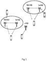
- Figure 1 describes a dual connectivity setup.
- only one SeNB is connected to UE, however, more than one SeNB can serve the UE in general.
- dual connectivity is a UE-specific feature and a network node can support a dual connected UE and a legacy UE at the same time.
- the anchor node and booster node roles are defined from a UE point of view. This means that a node that acts as an anchor node to one UE may act as booster node to another UE. Similarly, though the UE reads the system information from the anchor node, a node acting as a booster node to one UE, may or may not distribute system information to another UE.
- the MeNB may provide system information, terminate control plane and it can also terminate user plane
- the SeNB an terminate the control plane but can only terminate the user plane
- dual connectivity allows a UE to be connected to two nodes to receive data from both nodes to increase its data rate.
- This user plane aggregation achieves similar benefits as carrier aggregation using network nodes that are not connected by low-latency backhaul/network connection. Due to this lack of low-latency backhaul, the scheduling and HARQ-ACK feedback from the UE to each of the nodes will need to be performed separately. That is, it's expected the UE shall have two UL transmitters to transmit UL control and data to the connected nodes.
- the anchor node provides a macro cell while the booster cell provides a lower power (e.g., micro, pico, or femto) cell (at least partially within the coverage area of the macro cell).
- the UE connection may be anchored to the macro cell via an anchor carrier while data rate is boosted via a lower power cell through a booster carrier.
- dual connectivity may be termed dual-layer connectivity since the UE has simultaneous connections to both macro and low-power layers.
- the macro cell may provide system information and/or basic RRC signaling (such as paging or mobility related signaling), with all data services (but no system information) being provided by the low-power cell (i.e., the low-power cell is "macro assisted") for that particular UE.
- the macro cell may also provide at least some data services (e.g., lower rate or high reliability data services), whereas the low-power cell provides higher rate data services.
- the UE In dual connectivity the UE will be connected to two eNodeBs simultaneously; MeNB and SeNB. Each of them may have one or more associated SCells which may be configured for DL, or DL and UL CA operation.
- the SCells are time-aligned to the MeNB and SeNB, respectively, but the MeNB and SeNB may or may not be time aligned with respect to their frame timings and/or their respective system frame number (SFN).
- SFN system frame number
- MeNB and SeNB independently perform some of the operations and procedures related to the UE in dual connectivity. For example MeNB can only activate and deactivate serving cells (e.g. SCells) associated with MeNB. SeNB can only activate and deactivate serving cells (e.g. SCells) associated with SeNB. Cross-eNB activation/deactivation is not supported.
- serving cells e.g. SCells
- SeNB can only activate and deactivate serving cells (e.g. SCells) associated with SeNB.
- Cross-eNB activation/deactivation is not supported.
- the configuration and simultaneous activation, as well as release (hence deactivation), of Special SCell also called as Primary Secondary Cell (PSCell) belonging to SeNB is done by MeNB, and hence that the above mentioned agreement shall only refer to SCells associated with MCG and SCG, respectively.
- the PSCell is responsible for performing operations within SCG for example operations such as configuration, deconfiguration, activation and deactivation of SCell(s) in SCG.
- the MeNB configures and activates the Special SCell but not any of the ordinary SCells in the SCG.
- the MeNB deactivates and releases the Special SCell but not any of the ordinary SCells in the SCG.
- the activation time may be considerable longer than currently assumed for legacy CA.
- the fact that the Special SCell goes directly into activated state upon configuration means that the UE might not have had a chance to identify it before the activation, hence the activation might be blind.
- the UE will also have to acquire SFN timing difference to MeNB by reading MIB from the Special SCell as part of the activation procedure, for purpose of aligning e.g. DRX cycle offset and measurement gap offset between MeNB and SeNB. Acquiring SFN adds an extra 50ms to the activation time (see analysis in R4-142726) both for regular and blind activation of the Special SCell.
- the SCell activation times are 24 and 34ms for regular and blind activation, respectively; 3GPP TS 36.133 section 7.7.
- 3GPP TS 36.133 section 7.7 For those numbers to apply it is assumed that the SCell has already been configured by the network via RRC Connection Reconfiguration message (3GPP TS 36.331 section 5.3.5) when the MAC control element activating the cell is received (3GPP TS 36.321 section 5.13).
- RRC Connection Reconfiguration message 3GPP TS 36.331 section 5.3.5
- the MAC control element activating the cell 3GPP TS 36.321 section 5.13.
- the RRC procedure delay needs to be taken into account - often 15ms is assumed for such delay.
- radio network node or simply “network node (NW node)
- NW node network node
- It can be any kind of network node which may comprise of base station, radio base station, base transceiver station, base station controller, network controller, evolved Node B (eNB), Node B, relay node, access point, radio access point, radio network point, Remote Radio Unit (RRU) Remote Radio Head (RRH) etc.
- eNB evolved Node B
- RRU Remote Radio Unit
- RRH Remote Radio Head
- first node and second node are used, where first node can be MeNB and second node can be SeNB.
- the first node and second node may also be interchangeably called as first radio node and second radio node respectively or a first network node and a second network node respectively.
- CC allocation of the UE is done by the first node or by the second node or by any other network node.
- node may be used which can be first or second node e.g. in case both first and second node can perform the same task.
- yet third network node may be used.
- the third network node may be used for configuring or managing the first and/or second network node.
- Examples of the third network node are core network node, SON, O&M, OSS, another eNode B, or a master or central node.
- the first and the third network nodes or the second and the third network nodes may be the same.
- yet another node called fourth network node may be used.
- the fourth network node may be neighboring to the first and/or the second network nodes.
- the fourth network node can be used as MeNB or SeNB for the UE configured in DC operation.
- UE capability in terms of the maximum number of CCs that the UE can use for dual connectivity operation (i.e. for CA of CCs from different eNBs i.e. MeNB and SeNB) is used.
- capability refers to the maximum total number of CCs from all network nodes involved in DC operation of the UE.
- capability refers to the maximum number of CCs per network node involved in DC operation of the UE.
- capability information is obtained in the network node based on pre-defined rule, information received from the UE, information received from another network node or any combination thereof.
- a component carrier also interchangeably called as carrier, PCC or SCC is configured at the UE by the network node using higher layer signaling e.g. by sending RRC configuration message to the UE.
- the configured CC is used by the network node for serving the UE on or as the serving cell (e.g. on PCell, PSCell, SCell etc) of the configured CC.
- the configured CC is also used by the UE for performing one or more radio measurements (e.g. RSRP, RSRQ etc) on the cells operating on the CC e.g. PCell, SCell or PSCell and neighboring cells.
- determining is used and it may also be obtaining, receiving, detecting, identifying etc, information or parameter etc.
- the synchronized operation herein means that the UE can perform DC operation provided the received time difference ( ⁇ t) between the signals received at the UE from the component carriers, CCs, belonging to the MCG and SCG are within a certain threshold e.g. ⁇ 30 ⁇ s.
- Case 2 The unsynchronized operation herein means that the UE can perform DC operation regardless of the received time difference ( ⁇ t) between the signals received at the UE from the CCs belonging to the MCG and SCG e.g. for any value of ⁇ t.
- ⁇ t Maximum receive timing difference ( ⁇ t) at the UE consists of two components, namely:
- the synchronized case essentially means that MeNB and SeNB transmit timing need to be synchronized up to certain level of time accuracy, while unsynchronized case provides a random value for synchronization accuracy (i.e. anything up to 1 ms), which is higher than the accuracy required in synchronized case.
- the receive timing difference referred to is the received timing misalignment between two received signals at the UE. In other words, this is not the transmit timing mismatch levels between the MeNB and SeNB.
- Dual Tx/Rx means that we will potentially have separate power amplifiers, PAs, for separate links, thus no strict synchronization requirement is needed. This is the case 2 as mentioned above. Define requirements for the un-synchronized case, may also work for synchronized case.
- the received time difference of radio signals from MeNB and SeNB may also incorporate additional delay introduced by the multipaths due to the characteristics of the radio environment.
- the delay spread of multiple paths received at the UE may typically be in the order of 1-3 ⁇ s.
- the channel delay spread due to multipath effect of the signals observed at the UE is relatively smaller e.g. less than 1 ⁇ s.
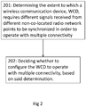
- Figure 2 illustrates a method performed by a network node that may be operable in a wireless communication network supporting dual connectivity. The method is suitable e.g. for deciding a suitable dual connectivity operation mode for a certain WCD e.g. synchronized or unsynchronized operation modes.
- the method comprises determining 201 the extent to which a wireless communication device requires different signals received from different non-co-located radio network points to be synchronized in order to operate with multiple connectivity.
- the method further comprises deciding 202 whether to configure the WCD to operate with multiple connectivity, based on said determination.
- the method comprises determining the extent to which a wireless communication device requires different signals received from different non-co-located radio network points to be synchronized in order to operate with multiple connectivity.
- the device When operating with multiple connectivity, the device maintains simultaneous connections to different radio network points which employ independent radio resource scheduling and feedback signaling. The points do so because they are connected by a non-ideal backhaul that has finite backhaul delay, rendering tight coordination between the points infeasible.
- determination may be made using any approach described in step 1 of section "Initiating dual connectivity operation considering UE synchronization capability".
- the determining 201 may comprise receiving from the WCD, a WCD capability information indicating the capability of the WCD to operate in synchronized and/or in a unsynchronized multiple connectivity.
- the method further comprises deciding whether to configure the device to operate with multiple connectivity, based on the above determination. In some embodiments, for example, if the WCD does not require different received signals to be synchronized to any extent (i.e., the device is capable of unsynchronized multiple connectivity), the network node decides to configure the device to operate with multiple connectivity.
- the network node further comprises configuring the device to operate with multiple connectivity.
- the network node decides to configure the device to operate with multiple connectivity only if the amount of synchronization that the device requires can be provided by two or more radio network points to which the device can simultaneously connect.
- the network node further comprises configuring the WCD to operate with multiple connectivity only if the amount of synchronization that the WCD requires can be provided by two or more radio network nodes.
- the network node in some embodiments identifies the particular amount of synchronization required, if not already identified in the determination. That is, in some embodiments the above determination simply entails determining whether the device requires at least some synchronization, without identifying the particular amount of synchronization required. In these embodiments, therefore, the network node may further identify the particular amount of synchronization (e.g., in the form of a particular maximum RTD value that the device supports).
- the network node determines the amount of synchronization that the points in the candidate group can provide (E.g., in terms of a RTD between signals received by the device from the points in the candidate group).
- the network node may perform this determination using any of the approaches described in step 3 of section "Initiating dual connectivity operation considering UE synchronization capability". If at least one of the candidate groups can provide at least the amount of synchronization required by the device, the network node configures the device with multiple connectivity (e.g., configures the device to maintain simultaneous connections to the points in that candidate group).
- one or more embodiments herein generally including a method performed by a network node in a wireless communication system, as shown in figure 3 .
- the method includes determining the extent to which a wireless communication device requires different signals received from different non-co-located radio network points to be synchronized in order to operate with multiple connectivity.
- the device When operating with multiple connectivity, the device maintains simultaneous connections to different radio network points which employ independent radio resource scheduling and feedback signaling. The points do so because they are connected by a non-ideal backhaul that has finite backhaul delay, rendering tight coordination between the points infeasible.
- determination may be made using any approach described in step 1 of section "Initiating dual connectivity operation considering UE synchronization capability".
- the method further comprises controlling one or more radio operations performed by one of the radio network points and/or the device, based on said determination.
- the network node does so as needed to ensure that the extent of synchronization required by the device is provided by radio network points to which the device simultaneously connects.
- the network node in this case may for example control the transmit timing (e.g., DL frame timing) with which one or more radio network points transmit signals (see e.g., section "Adapting DC related radio operations based on UE synchronization capability”.1). Additionally or alternatively, the network node may control handover of the device to a particular radio network point that can provide the required extent of synchronization (see e.g., section "Adapting DC related radio operations based on UE synchronization capability".2).
- the network node does so as needed to coordinate (at least in a limited capacity) parameters related to inter-frequency measurement and/or sleep time periods across different ones of the radio network points (see e.g., sections "Adapting DC related radio operations based on UE synchronization capability”.3 and "Adapting DC related radio operations based on UE synchronization capability”.5).
- the network node may perform a number of operations related to dual connectivity.
- the steps performed in the network node may be:
- a network determines UE capability related to synchronized and/or unsynchronized DC operation of UE and decides whether to initiate DC operation and adjusts one or more radio procedures depending upon whether the UE is configured to operate in synchronized or unsynchronized DC.
- the method is typically performed by the first network node but it may also be performed by the second network node or even third network node or even it may involve more than one network nodes. The method is elaborated in the following sections:
- the network node e.g. first network node or second network node or even a third network node that manages the first and/or second network nodes
- embodiments in section "Initiating dual connectivity operation considering UE synchronization capability” may be implemented alone, or in combination with other embodiments herein (e.g., in combination with embodiments in section “Adapting DC related radio operations based on UE synchronization capability”).
- the network node may adapt one or more of the following operations or apply adjustment of one or more parameters in order to enhance the performance of DC operation.
- Each of the subsections under section "Adapting DC related radio operations based on UE synchronization capability" may be implemented independently from each other or in combination with each other.
- each of the subsections under section “Adapting DC related radio operations based on UE synchronization capability” may be implemented independently from or in combination with other embodiments herein in other sections.
- the method performed by the network node may comprise adjusting a transmit timing of either of the different radio network points based on the determined extent to which the WCD requires different signals received from different non-co-located radio network points to be synchronized
- the method performed by the network node may comprise initiating a cell change of the WCD to a radio network point based on the determined extent to which the WCD requires different signals received from different non-co-located radio network points to be synchronized
- the method performed by the network node may comprise adjusting a discontinuous reception parameter based on the determined extent to which the WCD requires different signals received from different non-co-located radio network points to be synchronized LTE has a number of power saving mechanisms, some of them are mentioned below:
- a UE is dimensioned to monitor the PDCCH. When the UE is ON, then it monitors the PDCCH, while in DRX mode, it remains in power saving mode.
- the RRC sets a cycle where the UE is operational for a certain period of time when all the scheduling and paging information is transmitted, this is the ON duration.
- the eNodeB knows that the UE is completely turned off and is not able to receive anything. This is the DRX time. Except when in DRX, the UE radio must be active to monitor PDCCH (to identify DL data). During DRX, the UE radio can be turned off.
- the DRX/DTX functionality is an effective way to reduce the UE's battery power usage, but at the same time introduces further constraints in the scheduler's tasks. The immediate consequence of them is an average increase of packets delivery delays.
- the short DRX/DTX represents a further attempt to exploit the inactivity periods of UE to save even more power. This further saving could be remarkable with certain types of traffic, but can also be very limited with others, like VoIP.
- DRX is configured by the RRC mechanisms; it may have long or short "off durations.
- the transition between long DRX and short DRX is determined by the eNB (MAC commands) or by the UE based on an activity timer.
- the UE can be off for a longer period of time. For packets arriving more often, the DRX interval is reduced during this period.
- the ON duration can be as small as 1 ms.
- the ON duration can be as small as 1 ms.
- PCell and SCell in CA. That means PCell and SCell reception times should be well within DRX ON.
- the NW has to adapt DRX On duration.
- the first and the second network nodes configure the UE in DC operation with DRX cycles independently.
- Each network node may also configure the UE with 2 DRX cycles: short DRX and long DRX cycles.
- a first set of the DRX cycles and a second set of the DRX cycles are configured for receiving signals from the serving cells served by the first network node and from the serving cells served by the second network node respectively.
- the network node may adjust one or more parameters related to the one or both of the first set of DRX cycles and/or of the second set of DRX cycles.
- the DRX related parameters are ON duration timer, DRX cycle length, inactivity timer etc.
- the adjustment of the DRX related parameters and the type of the parameter to be adjusted may be triggered based on whether the DC operation is synchronized or unsynchronized. For example when the DC operation is unsynchronized then the network node may configure a longer value of the ON duration timer in at least the first or the second set of the DRX cycles e.g. 20 ms or longer. This is to allow the UE to activate the receiver once during first and second set of the DRX cycles for receiving signals from both the first and the second network nodes. In yet another example if the UE operates in synchronized DC mode then the network node may decide to configure the UE with a shorter ON duration timer e.g. 2 ms.
- the network nodes can also coordinate among themselves (e.g. between first and the second network nodes over X2) to decide whether to align the DRX related parameters and also the DRX parameters and their values to be aligned.
- the third network node may decide whether one or more DRX related parameters should be aligned or not and indicate this to the first and/or to the second network nodes. If the parameters are to be aligned then the third network node may also inform the first and/or the second network nodes with the values of DRX parameters to be aligned for the UE in DC operation. The third network node may also inform the UE about the alignment of the DRX related parameters or configure the UE with the said adjusted DRX related parameters. Additionally or alternatively the first and/or the second network nodes may also configure the UE with the said adjusted parameters related to the DRX.
- the first network node has provided information to said UE on that the second (or third or more) network node is synchronized to the first network node on a radio frame basis, the first network node may for instance expect the activation time to be X ms and adjusts e.g. a timer for detection of failed activation accordingly.
- the first network node may expect the activation time to be Y>X ms, and adjusts said timer accordingly.
- X may be 89ms and Y may be 180ms, but also other values may be used.
- the first network node in case the first network node has acquired information on the radio conditions in the proximity of the first UE, e.g. via reporting of mobility measurements from a second, a third, etc UEs in the same area, the first network node may take such information into account when determining the expected activation time. As an example embodiment, in good radio conditions the first network node may expect the activation of the first UE for a cell under a second network node to be shorter than when in bad radio conditions. The information on radio conditions may also be based on historic information on UE activation time for that area.
- a first network node may further take synchronization status for a second (or third or more) network node into account when determining the expected interruption time due to reconfiguration of RF when activating or deactivating a cell under the second (or third or more) network node.
- the first network node may expect interruption time similar to legacy CA (1ms or 5ms; 3GPP 36.133 section 7.7). However, if such information has not been provided to the UE, or it has been provided to the UE that the second network node is unsynchronized to the first network node, the first network node may expect the activation to cause an interruption that is longer than in legacy CA. For instance, each interruption may be extended by 1ms to cater for misaligned subframe timing (e.g. 2ms or 6ms).
- the expected interruption time has an impact on the expected BLER, and hence incorrect expectations may have an impact on the radio link adaptation, leading to more robust encoding (MCS) than called for by the radio conditions and as a result a reduced throughput both on user level and system level.
- MCS robust encoding
- the method performed by the network node may comprise adjusting a measurement gap configuration based on the determined extent to which the WCD requires different signals received from different non-co-located radio network points to be synchronized
- a second network node may take synchronization status to a first network node into account when configuring measurement gaps that are to be aligned with said kind of gaps in said first network node.
- the second network node may configure overlapping gaps of same length as used in said first network node. If on the other hand it is unaware, or aware of not being synchronized with said first network node, it may configure measurement gaps that are longer (1 or 2 ms longer) than for those used in said first network node (6ms) to take the misalignment into account and secure that the measurement gap on all carriers simultaneously is 6ms minus tolerances due to differences introduced by non-collocated cells under the same network node (e.g. up to 30.3us) and differences between TAGs (e.g. 31.5us).
- the second network node can avoid impact on system throughput and mobility by taking the synchronization status into account. If known by the second network node that it is synchronized to the first network node, it can follow legacy procedures regarding scheduling the UE immediately before and after a measurement gap. However if synchronization status is unknown to said second network node, or it is known that said second network node is unsynchronized with the first network node, the second network node may avoid scheduling the UE immediately before and/or after the measurement gap. For example the first and/or second network nodes may assume that the length of each gap is 8 ms instead of 6 ms. The network node may instead during these additional subframes (e.g. 2 subframes) schedule UEs which are not configured to operate in DC or UEs which are configured to operate in synchronized DC mode.
- additional subframes e.g. 2 subframes
- Some embodiments is performed occasionally or periodically so as to enable the network node to dynamically switch the device from employing synchronized multiple connectivity to employing unsynchronized multiple connectivity, and vice versa.
- the network node preferentially configures the device for unsynchronized multiple connectivity.
- the network node e.g. first network node and/or network node
- the UE supporting unsynchronized mode can be configured to operate in synchronized mode.
- the RTD of signals from the first and the second network nodes at the UE should be within certain limit e.g. 30 ⁇ s.
- the UE supporting both unsynchronized and synchronized modes of DC operation can also be configured from synchronized to unsynchronized mode or vice versa.
- the network node may decide to change the DC mode of operation based on one or more of the following criteria:
- Figure 4 illustrates a method in a wireless communication device.
- the method comprises determining 401 a receive timing difference between signals received at the wireless communication device from a candidate cell and a reference cell.
- the method further comprises comparing 402 the receive timing difference with a threshold.
- the method further comprises reporting 403 information to a network node about one or more cells whose determined receive timing difference are within the threshold.
- the steps performed at the WCD may according to some embodiments comprise obtaining information (autonomously triggered or based on request received from a network node) to determine one or more cells that are suitable for DC operation in unsynchronized and/or synchronized modes. Such information may thus be obtaining information indicating to the WCD that candidate cells should be determined. Alternatively or in addition the method may comprise triggering the reporting information to the network node autonomously or by a request from the network.
- the method may comprise comparing the timing difference (RTD) of signals received at the UE from a candidate cell and a reference cell with a threshold, wherein the threshold is pre-defined, configured by the network node or based on UE capability and wherein the reference cell is pre-defined, configured by the network node or autonomously decided by the UE;
- RTD timing difference
- the method may comprise deciding based on the said comparison one or more candidate cells which are suitable for synchronized or unsynchronized DC operation modes;
- the method may comprise transmitting information (e.g. recommended list of cells) about one or more cells that are suitable for synchronized and/or unsynchronized DC operation modes
- the information transmitted to the network node may comprise a cell identifier identifying the one or more cells whose determined receive timing difference are within the threshold.
- the reference cell is in one example a serving cell or a strongest cell as measured by the WCD or a cell with the shortest propagation delay as measured by the WCD.
- the serving cell is the cell serving the WCD.
- the threshold may pre-defined or configured by the network node or based on a WCD capability, said WCD capability indicates the extent to which the WCD requires different signals received from different cells to be synchronized in order to operate with the different cells.
- the capability may be based on the number of transmitters and/or receivers supported by the WCD.
- the step of the autonomous determination of the candidate cells for DC operation can be triggered based on one or more of the following criteria:
- a cell to be considered by the UE as the reference cell can be:
- Examples of the reference cell are:
- the UE is explicitly configured by the network node (e.g. first network node and/or second network node and/or third network node):
- the UE upon receiving the request determines the RTD between the reference cell and the cells which are indicated by the network node.
- the definition of the reference cell is the same as described in section "UE autonomous determination of candidate cells for DC operation".
- the UE determines the cell to be feasible for synchronized DC operation provided its RTD with respect to the reference cell is within the threshold.
- the UE then signals the information about cells which are feasible for synchronized DC operation and/or for unsynchronized DC operation to the network node.
- a network node further comprising receiving information from the WCD about one or more cells whose determined receive timing difference are within a threshold, wherein said receive timing difference is between signals received at the wireless communication device from a candidate cell and a reference cell and further base the deciding on the received information.
- the network node that receives information about one or more cells which are feasible for DC operation use the said information for one or more tasks as follows:
- figure 5 shows an example network node configured according to one or more embodiments herein.
- figure 5 also illustrates an example wireless communication device (e.g., UE) configured as described above (e.g., in section "Method in UE to initiate or recommend dual connectivity operation").
- UE wireless communication device
- the network node comprises communication interface circuits for communicating with one or more other nodes.
- the interface circuits comprise a transceiver for communication over an air interface with a radio node in a wireless communication network.
- the network node also comprises processing circuits for performing processing described herein, and memory for storing program code and data needed for operation.
- the processing circuits may comprise one or more processors, hardware circuits, firmware, or a combination thereof.
- Memory may comprise one or more volatile and/or non-volatile memory devices.
- Program code for controlling operation of the network node is stored in a non-volatile memory, such as a read-only memory or flash memory. Temporary data generated during operation may be stored in random access memory.
- the program code stored in memory when executed by the processing circuit, causes the processing circuit to perform the methods shown above.
- FIG. 6a An exemplifying embodiment of a first network node, such as the one exemplified as illustrated in a general manner in figure 6a .
- the network node 600 is configured to perform at least one of the method embodiments described above, e.g. with reference to any of figure 2-3 .
- the network node 600 is associated with the same technical features, objects and advantages as the previously described method embodiments. The network node will be described in brief in order to avoid unnecessary repetition.
- the network node may be implemented and/or described as follows:
- the network node 600 may be configured to support multiple connectivity and to be operable in a communication network supporting multiple connectivity.
- the network node 600 comprises processing circuitry 601 and a communication interface 602.
- the processing circuitry 601 is configured to determine the extent to which a wireless communication device, WCD, requires different signals received from different non-co-located radio network points to be synchronized in order to operate with multiple connectivity.
- the processing circuitry 601 is further configured to decide whether to configure the WCD to operate with multiple connectivity, based on said determination.
- I/O Input/Output
- the processing circuitry 601 could, as illustrated in figure 6b , comprise processing means, such as a processor 603, e.g. a CPU, and a memory 604 for storing or holding instructions.
- the memory would then comprise instructions, e.g. in form of a computer program 605, which when executed by the processing means 603 causes the network node 600 to perform the actions described above.
- the processing circuitry 601 comprises a determining unit 606, configured to cause the network node to determine the extent to which a wireless communication device, WCD, requires different signals received from different non-co-located radio network points to be synchronized in order to operate with multiple connectivity.
- the processing circuitry further comprises a deciding unit 607, configured to decide whether to configure the WCD to operate with multiple connectivity, based on said determination.
- the network node described above could be configured for the different method embodiments described herein such as: being configured to receive from the WCD, a WCD capability information indicating the capability of the UE to operate in synchronized and/or in a unsynchronized multiple connectivity; or alternatively or in addition being configured to configuring the UE on how to operate; or alternatively or in addition being configured to adjust any of the procedures discussed above; or alternatively or in addition being configured to receive information from a WCD about one or more cells whose determined receive timing difference are within a threshold.
- the network node 600 may be assumed to comprise further functionality, for carrying out regular network node functions.
- FIG. 7a An exemplifying embodiment of a wireless communication device, such as the one exemplified as a UE, and denoted "UE" above, is illustrated in a general manner in figure 7a .
- the wireless communication device will also here be denoted UE, as an example.
- the UE 700 is configured to perform at least one of the method embodiments described above, e.g. with reference to figure 4 .
- the UE 700 is associated with the same technical features, objects and advantages as the previously described method embodiments.
- the UE will be described in brief in order to avoid unnecessary repetition.
- the UE may be implemented and/or described as follows:
- the WCD 700 may be configured to support multiple connectivity and to be operable in a communication network supporting multiple connectivity.
- the UE 700 comprises processing circuitry 701 and a communication interface 702.
- the processing circuitry 701 is configured to, determine a receive timing difference between signals received at the wireless communication device from a candidate cell and a reference cell.
- the processing circuitry 701 is further configured to, compare the receive timing difference with a threshold.
- the processing circuitry 701 is further configured to, report information to a network node about one or more cells whose determined receive timing difference are within the threshold.
- I/O Input/Output
- the processing circuitry 701 could, as illustrated in figure 7b , comprise processing means, such as a processor 703, e.g. a CPU, and a memory 704 for storing or holding instructions.
- the memory would then comprise instructions, e.g. in form of a computer program 705, which when executed by the processing means 703 causes the UE 700 to perform the actions described above.
- the processing circuitry 701 comprises a determining unit 706, configured to determine a receive timing difference between signals received at the wireless communication device from a candidate cell and a reference cell.
- the processing circuitry further comprises a comparing unit 707, configured to cause the UE to, compare the receive timing difference with a threshold.
- the processing circuitry further comprises a reporting unit 708, configured to cause the UE to, report information to a network node about one or more cells whose determined receive timing difference are within the threshold.
- the UE described above could be configured for the different method embodiments described herein, such as to trigger the report of information to the network node autonomously or by a request from the network.
- the UE 700 may be assumed to comprise further functionality, for carrying out regular UE functions.
- Particular examples include one or more suitably configured digital signal processors and other known electronic circuits, e.g. discrete logic gates interconnected to perform a specialized function, or Application Specific Integrated Circuits (ASICs).
- digital signal processors and other known electronic circuits, e.g. discrete logic gates interconnected to perform a specialized function, or Application Specific Integrated Circuits (ASICs).
- ASICs Application Specific Integrated Circuits
- At least some of the steps, functions, procedures, modules, units and/or blocks described above may be implemented in software such as a computer program for execution by suitable processing circuitry including one or more processing units.
- the software could be carried by a carrier, such as an electronic signal, an optical signal, a radio signal, or a computer readable storage medium before and/or during the use of the computer program in the network nodes.
- a carrier such as an electronic signal, an optical signal, a radio signal, or a computer readable storage medium before and/or during the use of the computer program in the network nodes.
- At least part of the network nodes described above may be implemented in a so-called cloud solution, referring to that the implementation may be distributed, and the network nodes therefore may be so-called virtual nodes or virtual machines.
- the flow diagram or diagrams presented herein may be regarded as a computer flow diagram or diagrams, when performed by one or more processors.
- a corresponding apparatus may be defined as a group of function modules, where each step performed by the processor corresponds to a function module.
- the function modules are implemented as a computer program running on the processor.
- processing circuitry includes, but is not limited to, one or more microprocessors, one or more Digital Signal Processors, DSPs, one or more Central Processing Units, CPUs, and/or any suitable programmable logic circuitry such as one or more Field Programmable Gate Arrays, FPGAs, or one or more Programmable Logic Controllers, PLCs. That is, the units or modules in the arrangements in the different nodes described above could be implemented by a combination of analog and digital circuits, and/or one or more processors configured with software and/or firmware, e.g. stored in a memory.
- processors may be included in a single application-specific integrated circuitry, ASIC, or several processors and various digital hardware may be distributed among several separate components, whether individually packaged or assembled into a system-on-a-chip, SoC.
- ASIC application-specific integrated circuitry
- SoC system-on-a-chip
Landscapes
- Engineering & Computer Science (AREA)
- Computer Networks & Wireless Communication (AREA)
- Signal Processing (AREA)
- Quality & Reliability (AREA)
- Physics & Mathematics (AREA)
- Electromagnetism (AREA)
- Mobile Radio Communication Systems (AREA)
Claims (12)
- Procédé dans un dispositif de communication sans fil, fonctionnant dans un réseau de communication sans fil prenant en charge une connectivité multiple, le procédé comprenant- la transmission, à un nœud de réseau, d'informations de capacité indiquant une capacité du dispositif de communication sans fil de fonctionner dans un mode de fonctionnement à connectivité multiple synchronisé et désynchronisé ;- la détermination (401) d'une différence temporelle de réception entre des signaux reçus au niveau du dispositif de communication sans fil à partir d'une cellule candidate et d'une cellule de référence ;- la comparaison (402) de la différence temporelle de réception avec un seuil ;- le rapport (403) d'informations au nœud de réseau concernant une ou plusieurs cellules candidates dont la différence temporelle de réception déterminée est en deçà du seuil ;- la réception, en réponse au rapport, d'une première configuration à partir du nœud de réseau pour commuter du mode de fonctionnement à connectivité multiple synchronisé à désynchronisé ou inversement ; et- la commutation du mode de fonctionnement à connectivité multiple synchronisé à désynchronisé ou inversement.
- Procédé selon la revendication 1, dans lequel les informations au nœud de réseau comprennent un identificateur de cellule identifiant les une ou plusieurs cellules candidates dont la différence temporelle de réception déterminée est en deçà du seuil.
- Procédé selon l'une quelconque des revendications 1 à 2, dans lequel la cellule de référence est une cellule de desserte ou une cellule la plus forte telle que mesurée par le dispositif de communication sans fil ou une cellule avec le plus court retard de propagation tel que mesuré par le dispositif de communication sans fil.
- Procédé selon l'une quelconque des revendications 1 à 3, dans lequel le seuil est prédéfini ou configuré par le nœud de réseau ou basé sur les informations de capacité, lesdites informations de capacité indiquant en outre la mesure dans laquelle le dispositif de communication sans fil nécessite que différents signaux reçus à partir de différentes cellules soient synchronisés afin de fonctionner avec les différentes cellules.
- Procédé selon la revendication 4, dans lequel les informations de capacité sont basées sur le nombre d'émetteurs et/ou de récepteurs pris en charge par le dispositif de communication sans fil.
- Procédé selon l'une quelconque des revendications 1 à 5, comprenant en outre déclencher les informations de rapport au nœud de réseau de manière autonome ou par une requête provenant du réseau.
- Dispositif de communication sans fil (700) utilisable dans un réseau de communication prenant en charge une connectivité multiple, le dispositif de communication sans fil (700) ayant des moyens configurés pour- transmettre, à un nœud de réseau (600), des informations de capacité indiquant la capacité du dispositif de communication sans fil de fonctionner dans un mode de fonctionnement à connectivité multiple synchronisé et désynchronisé ;- déterminer une différence temporelle de réception entre des signaux reçus au niveau du dispositif de communication sans fil (700) à partir d'une cellule candidate et d'une cellule de référence ;- comparer la différence temporelle de réception avec un seuil ;- rapporter des informations au nœud de réseau (600) concernant une ou plusieurs cellules candidates dont la différence temporelle de réception déterminée est en deçà du seuil ;- recevoir, en réponse au rapport, une première configuration à partir du nœud de réseau (600) pour commuter du mode de fonctionnement à connectivité multiple synchronisé à désynchronisé ou inversement ; et- commuter le mode de fonctionnement à connectivité multiple synchronisé à désynchronisé ou inversement.
- Dispositif de communication sans fil (700) selon la revendication 7, dans lequel les informations au nœud de réseau (600) comprennent un identificateur de cellule identifiant les une ou plusieurs cellules candidates dont la différence temporelle de réception déterminée est en deçà du seuil.
- Dispositif de communication sans fil (700) selon l'une quelconque des revendications 7 à 8, dans lequel la cellule de référence est une cellule de desserte ou une cellule la plus forte telle que mesurée par le dispositif de communication sans fil (700) ou une cellule avec le plus court retard de propagation tel que mesuré par le dispositif de communication sans fil (700).
- Dispositif de communication sans fil (700) selon l'une quelconque des revendications 7 à 9, dans lequel le seuil est prédéfini ou configuré par le nœud de réseau (600) ou basé sur les informations de capacité, lesdites informations de capacité indiquant en outre la mesure dans laquelle le dispositif de communication sans fil (700) nécessite que différents signaux reçus à partir de différentes cellules soient synchronisés afin de fonctionner avec les différentes cellules.
- Dispositif de communication sans fil (700) selon la revendication 10, dans lequel les informations de capacité sont basées sur le nombre d'émetteurs et/ou de récepteurs pris en charge par le dispositif de communication sans fil (700).
- Dispositif de communication sans fil (700) selon l'une quelconque des revendications 7 à 11, configuré en outre pour déclencher le rapport d'informations au nœud de réseau (600) de manière autonome ou par une requête provenant du réseau.
Applications Claiming Priority (2)
| Application Number | Priority Date | Filing Date | Title |
|---|---|---|---|
| US201462000385P | 2014-05-19 | 2014-05-19 | |
| PCT/SE2015/050561 WO2015178835A1 (fr) | 2014-05-19 | 2015-05-19 | Adaptation de procédures de connectivité double |
Publications (2)
| Publication Number | Publication Date |
|---|---|
| EP3146790A1 EP3146790A1 (fr) | 2017-03-29 |
| EP3146790B1 true EP3146790B1 (fr) | 2020-11-25 |
Family
ID=53433243
Family Applications (1)
| Application Number | Title | Priority Date | Filing Date |
|---|---|---|---|
| EP15729956.1A Not-in-force EP3146790B1 (fr) | 2014-05-19 | 2015-05-19 | Adaptation de procédures de connectivité double |
Country Status (3)
| Country | Link |
|---|---|
| US (1) | US10225028B2 (fr) |
| EP (1) | EP3146790B1 (fr) |
| WO (1) | WO2015178835A1 (fr) |
Families Citing this family (16)
| Publication number | Priority date | Publication date | Assignee | Title |
|---|---|---|---|---|
| US9820332B2 (en) * | 2014-08-07 | 2017-11-14 | Lg Electronics Inc. | Method for deactivating SCells during SCG change procedure and a device therefor |
| WO2017022870A1 (fr) * | 2015-08-03 | 2017-02-09 | Samsung Electronics Co., Ltd. | Procédé et appareil pour un accès initial dans un système de communication sans fil |
| US10772101B2 (en) * | 2015-12-08 | 2020-09-08 | Huawei Technologies Co., Ltd. | Systems and methods for determining air interface configuration |
| MY178128A (en) * | 2016-01-07 | 2020-10-05 | Nokia Technologies Oy | Method of indication of available radio resources |
| ES2953860T3 (es) * | 2016-07-22 | 2023-11-16 | Abeeway | Procedimiento y sistema de asistencia a la geolocalización de dispositivos nodales de una red de RF asíncrona |
| WO2018155236A1 (fr) * | 2017-02-24 | 2018-08-30 | 京セラ株式会社 | Dispositif de communication sans fil, et processeur |
| CN111183706B (zh) * | 2017-06-16 | 2023-11-14 | 苹果公司 | 在双重连通中使能非活跃模式的gNB的装置 |
| CN109644521B (zh) | 2017-06-16 | 2021-04-20 | 瑞典爱立信有限公司 | 用于测量报告的方法、装置和计算机可读介质 |
| EP3653000A4 (fr) | 2017-07-11 | 2020-08-12 | Telefonaktiebolaget LM Ericsson (Publ) | Procédés et appareils de gestion de la synchronisation d'un dispositif sans fil |
| CN110958070B (zh) * | 2018-09-27 | 2021-08-20 | 华为技术有限公司 | 一种参考时间确定方法及装置 |
| EP3918838B1 (fr) * | 2019-01-30 | 2025-09-17 | Telefonaktiebolaget LM Ericsson (publ) | Déclenchement de mobilité conditionnelle sur la base d'informations de faisceau |
| WO2020258245A1 (fr) * | 2019-06-28 | 2020-12-30 | Oppo广东移动通信有限公司 | Procédé de traitement d'informations utilisé pour une commutation et dispositif de réseau |
| CN114270959A (zh) | 2019-11-08 | 2022-04-01 | Oppo广东移动通信有限公司 | 时钟同步方法及相关装置 |
| US11616558B2 (en) * | 2019-11-20 | 2023-03-28 | Qualcomm Incorporated | Procedural delays and scheduling restriction based on component carrier groups |
| US20230309165A1 (en) * | 2020-09-25 | 2023-09-28 | Softbank Corp. | User terminal, base station, and radio communication method |
| EP4278755A4 (fr) * | 2021-01-12 | 2024-10-16 | Lenovo (Beijing) Limited | Procédés et appareils de mécanisme amélioré pour sn désactivé ou dormant |
Citations (1)
| Publication number | Priority date | Publication date | Assignee | Title |
|---|---|---|---|---|
| US20110216757A1 (en) * | 2008-11-06 | 2011-09-08 | Juergen Michel | Apparatus and Method for Decentralized Synchronization |
Family Cites Families (7)
| Publication number | Priority date | Publication date | Assignee | Title |
|---|---|---|---|---|
| US20090253470A1 (en) * | 2008-04-02 | 2009-10-08 | Shugong Xu | Control of user equipment discontinuous reception setting via mac lcid |
| US20120309394A1 (en) * | 2010-09-16 | 2012-12-06 | Qualcomm Incorporated | Apparatus and methods for hand-in to a femto node |
| US8948157B2 (en) * | 2011-09-07 | 2015-02-03 | Qualcomm Incorporated | Method and apparatus for distributed synchronization in femtocell networks |
| US9504057B2 (en) * | 2012-05-11 | 2016-11-22 | Apple Inc. | Methods and apparatus for in-device coexistence detection and mitigation |
| US11356216B2 (en) * | 2013-01-10 | 2022-06-07 | Texas Instruments Incorporated | Methods and apparatus for dual connectivity operation in a wireless communication network |
| US10075929B2 (en) * | 2013-09-16 | 2018-09-11 | Lg Electronics Inc. | Method and apparatus for network synchronization |
| JP5970489B2 (ja) * | 2014-01-30 | 2016-08-17 | 株式会社Nttドコモ | 移動通信システム及び移動局装置 |
-
2015
- 2015-05-19 WO PCT/SE2015/050561 patent/WO2015178835A1/fr not_active Ceased
- 2015-05-19 US US14/763,237 patent/US10225028B2/en not_active Expired - Fee Related
- 2015-05-19 EP EP15729956.1A patent/EP3146790B1/fr not_active Not-in-force
Patent Citations (1)
| Publication number | Priority date | Publication date | Assignee | Title |
|---|---|---|---|---|
| US20110216757A1 (en) * | 2008-11-06 | 2011-09-08 | Juergen Michel | Apparatus and Method for Decentralized Synchronization |
Also Published As
| Publication number | Publication date |
|---|---|
| US20160255671A1 (en) | 2016-09-01 |
| US10225028B2 (en) | 2019-03-05 |
| WO2015178835A1 (fr) | 2015-11-26 |
| EP3146790A1 (fr) | 2017-03-29 |
Similar Documents
| Publication | Publication Date | Title |
|---|---|---|
| EP3146790B1 (fr) | Adaptation de procédures de connectivité double | |
| JP6517983B2 (ja) | オン/オフ方式によるスモールセルにおける測定の支援 | |
| US10812962B2 (en) | Aligning measurement gaps and discovery signals | |
| US10420028B2 (en) | Handling interruptions during DRX on durations | |
| EP3195688B1 (fr) | Configuration de cycle drx dans une connectivité double | |
| EP3711183B1 (fr) | Équipement utilisateur et noeud de réseau pour configurer des mesures de cellules et de faisceaux dans un système de communication sans fil | |
| US11678370B2 (en) | Systems and methods for controlling wireless device feedback on secondary cell activation and deactivation via the unlicensed spectrum | |
| CN106465315B (zh) | Ue自主的无线资源配置扩展 | |
| US20190274100A1 (en) | System and Method for Activating and Deactivating Multiple Secondary Cells | |
| CN109792305B (zh) | 用于无线电链路测量配置的方法和设备 | |
| EP3100498B1 (fr) | Mesure sur une cellule secondaire (scell) scc et des signaux de découverte de marche/arrêt | |
| US10419962B2 (en) | Wireless device, network node and methods therefor, and computer programs | |
| US10064124B2 (en) | Communication device, network node, and computer program for communication and/or device-to-device operation in an out of coverage state | |
| US20160234718A1 (en) | D2d traffic balancing | |
| CN105594281A (zh) | 针对pbch的协调 | |
| US10645661B2 (en) | Configuring discovery signals | |
| CN117750423A (zh) | 预配置的测量间隙的激活/去激活 | |
| KR20150114890A (ko) | 단말의 세컨더리 셀 동작 제어 방법 및 그 장치 |
Legal Events
| Date | Code | Title | Description |
|---|---|---|---|
| STAA | Information on the status of an ep patent application or granted ep patent |
Free format text: STATUS: THE INTERNATIONAL PUBLICATION HAS BEEN MADE |
|
| PUAI | Public reference made under article 153(3) epc to a published international application that has entered the european phase |
Free format text: ORIGINAL CODE: 0009012 |
|
| STAA | Information on the status of an ep patent application or granted ep patent |
Free format text: STATUS: REQUEST FOR EXAMINATION WAS MADE |
|
| 17P | Request for examination filed |
Effective date: 20161107 |
|
| AK | Designated contracting states |
Kind code of ref document: A1 Designated state(s): AL AT BE BG CH CY CZ DE DK EE ES FI FR GB GR HR HU IE IS IT LI LT LU LV MC MK MT NL NO PL PT RO RS SE SI SK SM TR |
|
| AX | Request for extension of the european patent |
Extension state: BA ME |
|
| DAV | Request for validation of the european patent (deleted) | ||
| DAX | Request for extension of the european patent (deleted) | ||
| STAA | Information on the status of an ep patent application or granted ep patent |
Free format text: STATUS: EXAMINATION IS IN PROGRESS |
|
| 17Q | First examination report despatched |
Effective date: 20170921 |
|
| RIC1 | Information provided on ipc code assigned before grant |
Ipc: H04W 76/00 20180101AFI20200507BHEP Ipc: H04W 76/15 20180101ALN20200507BHEP Ipc: H04W 56/00 20090101ALI20200507BHEP Ipc: H04W 88/06 20090101ALN20200507BHEP |
|
| REG | Reference to a national code |
Ref country code: DE Ref legal event code: R079 Ref document number: 602015062490 Country of ref document: DE Free format text: PREVIOUS MAIN CLASS: H04W0076020000 Ipc: H04W0056000000 |
|
| RIC1 | Information provided on ipc code assigned before grant |
Ipc: H04W 88/06 20090101ALN20200520BHEP Ipc: H04W 56/00 20090101AFI20200520BHEP Ipc: H04W 76/15 20180101ALN20200520BHEP |
|
| RIC1 | Information provided on ipc code assigned before grant |
Ipc: H04W 56/00 20090101AFI20200602BHEP Ipc: H04W 76/15 20180101ALN20200602BHEP Ipc: H04W 88/06 20090101ALN20200602BHEP |
|
| RIC1 | Information provided on ipc code assigned before grant |
Ipc: H04W 56/00 20090101AFI20200608BHEP Ipc: H04W 88/06 20090101ALN20200608BHEP Ipc: H04W 76/15 20180101ALN20200608BHEP |
|
| RIC1 | Information provided on ipc code assigned before grant |
Ipc: H04W 88/06 20090101ALN20200624BHEP Ipc: H04W 56/00 20090101AFI20200624BHEP Ipc: H04W 76/15 20180101ALN20200624BHEP |
|
| GRAP | Despatch of communication of intention to grant a patent |
Free format text: ORIGINAL CODE: EPIDOSNIGR1 |
|
| STAA | Information on the status of an ep patent application or granted ep patent |
Free format text: STATUS: GRANT OF PATENT IS INTENDED |
|
| INTG | Intention to grant announced |
Effective date: 20200803 |
|
| GRAS | Grant fee paid |
Free format text: ORIGINAL CODE: EPIDOSNIGR3 |
|
| GRAA | (expected) grant |
Free format text: ORIGINAL CODE: 0009210 |
|
| STAA | Information on the status of an ep patent application or granted ep patent |
Free format text: STATUS: THE PATENT HAS BEEN GRANTED |
|
| AK | Designated contracting states |
Kind code of ref document: B1 Designated state(s): AL AT BE BG CH CY CZ DE DK EE ES FI FR GB GR HR HU IE IS IT LI LT LU LV MC MK MT NL NO PL PT RO RS SE SI SK SM TR |
|
| REG | Reference to a national code |
Ref country code: GB Ref legal event code: FG4D |
|
| REG | Reference to a national code |
Ref country code: CH Ref legal event code: EP |
|
| REG | Reference to a national code |
Ref country code: DE Ref legal event code: R096 Ref document number: 602015062490 Country of ref document: DE |
|
| REG | Reference to a national code |
Ref country code: AT Ref legal event code: REF Ref document number: 1339756 Country of ref document: AT Kind code of ref document: T Effective date: 20201215 |
|
| REG | Reference to a national code |
Ref country code: IE Ref legal event code: FG4D |
|
| REG | Reference to a national code |
Ref country code: AT Ref legal event code: MK05 Ref document number: 1339756 Country of ref document: AT Kind code of ref document: T Effective date: 20201125 |
|
| REG | Reference to a national code |
Ref country code: NL Ref legal event code: MP Effective date: 20201125 |
|
| PG25 | Lapsed in a contracting state [announced via postgrant information from national office to epo] |
Ref country code: GR Free format text: LAPSE BECAUSE OF FAILURE TO SUBMIT A TRANSLATION OF THE DESCRIPTION OR TO PAY THE FEE WITHIN THE PRESCRIBED TIME-LIMIT Effective date: 20210226 Ref country code: FI Free format text: LAPSE BECAUSE OF FAILURE TO SUBMIT A TRANSLATION OF THE DESCRIPTION OR TO PAY THE FEE WITHIN THE PRESCRIBED TIME-LIMIT Effective date: 20201125 Ref country code: RS Free format text: LAPSE BECAUSE OF FAILURE TO SUBMIT A TRANSLATION OF THE DESCRIPTION OR TO PAY THE FEE WITHIN THE PRESCRIBED TIME-LIMIT Effective date: 20201125 Ref country code: NO Free format text: LAPSE BECAUSE OF FAILURE TO SUBMIT A TRANSLATION OF THE DESCRIPTION OR TO PAY THE FEE WITHIN THE PRESCRIBED TIME-LIMIT Effective date: 20210225 Ref country code: PT Free format text: LAPSE BECAUSE OF FAILURE TO SUBMIT A TRANSLATION OF THE DESCRIPTION OR TO PAY THE FEE WITHIN THE PRESCRIBED TIME-LIMIT Effective date: 20210325 |
|
| PG25 | Lapsed in a contracting state [announced via postgrant information from national office to epo] |
Ref country code: AT Free format text: LAPSE BECAUSE OF FAILURE TO SUBMIT A TRANSLATION OF THE DESCRIPTION OR TO PAY THE FEE WITHIN THE PRESCRIBED TIME-LIMIT Effective date: 20201125 Ref country code: BG Free format text: LAPSE BECAUSE OF FAILURE TO SUBMIT A TRANSLATION OF THE DESCRIPTION OR TO PAY THE FEE WITHIN THE PRESCRIBED TIME-LIMIT Effective date: 20210225 Ref country code: SE Free format text: LAPSE BECAUSE OF FAILURE TO SUBMIT A TRANSLATION OF THE DESCRIPTION OR TO PAY THE FEE WITHIN THE PRESCRIBED TIME-LIMIT Effective date: 20201125 Ref country code: PL Free format text: LAPSE BECAUSE OF FAILURE TO SUBMIT A TRANSLATION OF THE DESCRIPTION OR TO PAY THE FEE WITHIN THE PRESCRIBED TIME-LIMIT Effective date: 20201125 Ref country code: LV Free format text: LAPSE BECAUSE OF FAILURE TO SUBMIT A TRANSLATION OF THE DESCRIPTION OR TO PAY THE FEE WITHIN THE PRESCRIBED TIME-LIMIT Effective date: 20201125 Ref country code: IS Free format text: LAPSE BECAUSE OF FAILURE TO SUBMIT A TRANSLATION OF THE DESCRIPTION OR TO PAY THE FEE WITHIN THE PRESCRIBED TIME-LIMIT Effective date: 20210325 |
|
| REG | Reference to a national code |
Ref country code: LT Ref legal event code: MG9D |
|
| PG25 | Lapsed in a contracting state [announced via postgrant information from national office to epo] |
Ref country code: HR Free format text: LAPSE BECAUSE OF FAILURE TO SUBMIT A TRANSLATION OF THE DESCRIPTION OR TO PAY THE FEE WITHIN THE PRESCRIBED TIME-LIMIT Effective date: 20201125 |
|
| PG25 | Lapsed in a contracting state [announced via postgrant information from national office to epo] |
Ref country code: RO Free format text: LAPSE BECAUSE OF FAILURE TO SUBMIT A TRANSLATION OF THE DESCRIPTION OR TO PAY THE FEE WITHIN THE PRESCRIBED TIME-LIMIT Effective date: 20201125 Ref country code: SK Free format text: LAPSE BECAUSE OF FAILURE TO SUBMIT A TRANSLATION OF THE DESCRIPTION OR TO PAY THE FEE WITHIN THE PRESCRIBED TIME-LIMIT Effective date: 20201125 Ref country code: LT Free format text: LAPSE BECAUSE OF FAILURE TO SUBMIT A TRANSLATION OF THE DESCRIPTION OR TO PAY THE FEE WITHIN THE PRESCRIBED TIME-LIMIT Effective date: 20201125 Ref country code: CZ Free format text: LAPSE BECAUSE OF FAILURE TO SUBMIT A TRANSLATION OF THE DESCRIPTION OR TO PAY THE FEE WITHIN THE PRESCRIBED TIME-LIMIT Effective date: 20201125 Ref country code: EE Free format text: LAPSE BECAUSE OF FAILURE TO SUBMIT A TRANSLATION OF THE DESCRIPTION OR TO PAY THE FEE WITHIN THE PRESCRIBED TIME-LIMIT Effective date: 20201125 Ref country code: SM Free format text: LAPSE BECAUSE OF FAILURE TO SUBMIT A TRANSLATION OF THE DESCRIPTION OR TO PAY THE FEE WITHIN THE PRESCRIBED TIME-LIMIT Effective date: 20201125 |
|
| PGFP | Annual fee paid to national office [announced via postgrant information from national office to epo] |
Ref country code: DE Payment date: 20210527 Year of fee payment: 7 Ref country code: FR Payment date: 20210525 Year of fee payment: 7 |
|
| REG | Reference to a national code |
Ref country code: DE Ref legal event code: R097 Ref document number: 602015062490 Country of ref document: DE |
|
| PG25 | Lapsed in a contracting state [announced via postgrant information from national office to epo] |
Ref country code: DK Free format text: LAPSE BECAUSE OF FAILURE TO SUBMIT A TRANSLATION OF THE DESCRIPTION OR TO PAY THE FEE WITHIN THE PRESCRIBED TIME-LIMIT Effective date: 20201125 |
|
| PGFP | Annual fee paid to national office [announced via postgrant information from national office to epo] |
Ref country code: GB Payment date: 20210527 Year of fee payment: 7 |
|
| PLBE | No opposition filed within time limit |
Free format text: ORIGINAL CODE: 0009261 |
|
| STAA | Information on the status of an ep patent application or granted ep patent |
Free format text: STATUS: NO OPPOSITION FILED WITHIN TIME LIMIT |
|
| PG25 | Lapsed in a contracting state [announced via postgrant information from national office to epo] |
Ref country code: AL Free format text: LAPSE BECAUSE OF FAILURE TO SUBMIT A TRANSLATION OF THE DESCRIPTION OR TO PAY THE FEE WITHIN THE PRESCRIBED TIME-LIMIT Effective date: 20201125 Ref country code: IT Free format text: LAPSE BECAUSE OF FAILURE TO SUBMIT A TRANSLATION OF THE DESCRIPTION OR TO PAY THE FEE WITHIN THE PRESCRIBED TIME-LIMIT Effective date: 20201125 Ref country code: NL Free format text: LAPSE BECAUSE OF FAILURE TO SUBMIT A TRANSLATION OF THE DESCRIPTION OR TO PAY THE FEE WITHIN THE PRESCRIBED TIME-LIMIT Effective date: 20201125 |
|
| 26N | No opposition filed |
Effective date: 20210826 |
|
| PG25 | Lapsed in a contracting state [announced via postgrant information from national office to epo] |
Ref country code: SI Free format text: LAPSE BECAUSE OF FAILURE TO SUBMIT A TRANSLATION OF THE DESCRIPTION OR TO PAY THE FEE WITHIN THE PRESCRIBED TIME-LIMIT Effective date: 20201125 Ref country code: ES Free format text: LAPSE BECAUSE OF FAILURE TO SUBMIT A TRANSLATION OF THE DESCRIPTION OR TO PAY THE FEE WITHIN THE PRESCRIBED TIME-LIMIT Effective date: 20201125 |
|
| REG | Reference to a national code |
Ref country code: CH Ref legal event code: PL |
|
| PG25 | Lapsed in a contracting state [announced via postgrant information from national office to epo] |
Ref country code: MC Free format text: LAPSE BECAUSE OF FAILURE TO SUBMIT A TRANSLATION OF THE DESCRIPTION OR TO PAY THE FEE WITHIN THE PRESCRIBED TIME-LIMIT Effective date: 20201125 Ref country code: LI Free format text: LAPSE BECAUSE OF NON-PAYMENT OF DUE FEES Effective date: 20210531 Ref country code: LU Free format text: LAPSE BECAUSE OF NON-PAYMENT OF DUE FEES Effective date: 20210519 Ref country code: CH Free format text: LAPSE BECAUSE OF NON-PAYMENT OF DUE FEES Effective date: 20210531 |
|
| REG | Reference to a national code |
Ref country code: BE Ref legal event code: MM Effective date: 20210531 |
|
| PG25 | Lapsed in a contracting state [announced via postgrant information from national office to epo] |
Ref country code: IE Free format text: LAPSE BECAUSE OF NON-PAYMENT OF DUE FEES Effective date: 20210519 |
|
| PG25 | Lapsed in a contracting state [announced via postgrant information from national office to epo] |
Ref country code: IS Free format text: LAPSE BECAUSE OF FAILURE TO SUBMIT A TRANSLATION OF THE DESCRIPTION OR TO PAY THE FEE WITHIN THE PRESCRIBED TIME-LIMIT Effective date: 20210325 |
|
| PG25 | Lapsed in a contracting state [announced via postgrant information from national office to epo] |
Ref country code: BE Free format text: LAPSE BECAUSE OF NON-PAYMENT OF DUE FEES Effective date: 20210531 |
|
| REG | Reference to a national code |
Ref country code: DE Ref legal event code: R119 Ref document number: 602015062490 Country of ref document: DE |
|
| GBPC | Gb: european patent ceased through non-payment of renewal fee |
Effective date: 20220519 |
|
| PG25 | Lapsed in a contracting state [announced via postgrant information from national office to epo] |
Ref country code: FR Free format text: LAPSE BECAUSE OF NON-PAYMENT OF DUE FEES Effective date: 20220531 |
|
| PG25 | Lapsed in a contracting state [announced via postgrant information from national office to epo] |
Ref country code: HU Free format text: LAPSE BECAUSE OF FAILURE TO SUBMIT A TRANSLATION OF THE DESCRIPTION OR TO PAY THE FEE WITHIN THE PRESCRIBED TIME-LIMIT; INVALID AB INITIO Effective date: 20150519 Ref country code: GB Free format text: LAPSE BECAUSE OF NON-PAYMENT OF DUE FEES Effective date: 20220519 Ref country code: DE Free format text: LAPSE BECAUSE OF NON-PAYMENT OF DUE FEES Effective date: 20221201 |
|
| PG25 | Lapsed in a contracting state [announced via postgrant information from national office to epo] |
Ref country code: CY Free format text: LAPSE BECAUSE OF FAILURE TO SUBMIT A TRANSLATION OF THE DESCRIPTION OR TO PAY THE FEE WITHIN THE PRESCRIBED TIME-LIMIT Effective date: 20201125 |
|
| PG25 | Lapsed in a contracting state [announced via postgrant information from national office to epo] |
Ref country code: MK Free format text: LAPSE BECAUSE OF FAILURE TO SUBMIT A TRANSLATION OF THE DESCRIPTION OR TO PAY THE FEE WITHIN THE PRESCRIBED TIME-LIMIT Effective date: 20201125 |
|
| PG25 | Lapsed in a contracting state [announced via postgrant information from national office to epo] |
Ref country code: MT Free format text: LAPSE BECAUSE OF FAILURE TO SUBMIT A TRANSLATION OF THE DESCRIPTION OR TO PAY THE FEE WITHIN THE PRESCRIBED TIME-LIMIT Effective date: 20201125 |
|
| PG25 | Lapsed in a contracting state [announced via postgrant information from national office to epo] |
Ref country code: TR Free format text: LAPSE BECAUSE OF FAILURE TO SUBMIT A TRANSLATION OF THE DESCRIPTION OR TO PAY THE FEE WITHIN THE PRESCRIBED TIME-LIMIT Effective date: 20201125 |