EP3146820B1 - Herse atelée et outil de travail du sol avec un tel attelage - Google Patents
Herse atelée et outil de travail du sol avec un tel attelage Download PDFInfo
- Publication number
- EP3146820B1 EP3146820B1 EP16189705.3A EP16189705A EP3146820B1 EP 3146820 B1 EP3146820 B1 EP 3146820B1 EP 16189705 A EP16189705 A EP 16189705A EP 3146820 B1 EP3146820 B1 EP 3146820B1
- Authority
- EP
- European Patent Office
- Prior art keywords
- harrow
- rank
- attachment
- tines
- drawbar
- Prior art date
- Legal status (The legal status is an assumption and is not a legal conclusion. Google has not performed a legal analysis and makes no representation as to the accuracy of the status listed.)
- Active
Links
Images















Classifications
-
- A—HUMAN NECESSITIES
- A01—AGRICULTURE; FORESTRY; ANIMAL HUSBANDRY; HUNTING; TRAPPING; FISHING
- A01B—SOIL WORKING IN AGRICULTURE OR FORESTRY; PARTS, DETAILS, OR ACCESSORIES OF AGRICULTURAL MACHINES OR IMPLEMENTS, IN GENERAL
- A01B61/00—Devices for, or parts of, agricultural machines or implements for preventing overstrain
- A01B61/04—Devices for, or parts of, agricultural machines or implements for preventing overstrain of the connection between tools and carrier beam or frame
- A01B61/044—Devices for, or parts of, agricultural machines or implements for preventing overstrain of the connection between tools and carrier beam or frame the connection enabling a yielding pivoting movement around a substantially horizontal and transverse axis
- A01B61/046—Devices for, or parts of, agricultural machines or implements for preventing overstrain of the connection between tools and carrier beam or frame the connection enabling a yielding pivoting movement around a substantially horizontal and transverse axis the device including an energy accumulator for restoring the tool to its working position
-
- A—HUMAN NECESSITIES
- A01—AGRICULTURE; FORESTRY; ANIMAL HUSBANDRY; HUNTING; TRAPPING; FISHING
- A01B—SOIL WORKING IN AGRICULTURE OR FORESTRY; PARTS, DETAILS, OR ACCESSORIES OF AGRICULTURAL MACHINES OR IMPLEMENTS, IN GENERAL
- A01B19/00—Harrows with non-rotating tools
- A01B19/02—Harrows with non-rotating tools with tools rigidly or elastically attached to a tool-frame
- A01B19/04—Harrows with non-rotating tools with tools rigidly or elastically attached to a tool-frame with two or more tool-frames
-
- A—HUMAN NECESSITIES
- A01—AGRICULTURE; FORESTRY; ANIMAL HUSBANDRY; HUNTING; TRAPPING; FISHING
- A01B—SOIL WORKING IN AGRICULTURE OR FORESTRY; PARTS, DETAILS, OR ACCESSORIES OF AGRICULTURAL MACHINES OR IMPLEMENTS, IN GENERAL
- A01B19/00—Harrows with non-rotating tools
- A01B19/02—Harrows with non-rotating tools with tools rigidly or elastically attached to a tool-frame
-
- A—HUMAN NECESSITIES
- A01—AGRICULTURE; FORESTRY; ANIMAL HUSBANDRY; HUNTING; TRAPPING; FISHING
- A01B—SOIL WORKING IN AGRICULTURE OR FORESTRY; PARTS, DETAILS, OR ACCESSORIES OF AGRICULTURAL MACHINES OR IMPLEMENTS, IN GENERAL
- A01B23/00—Elements, tools, or details of harrows
- A01B23/04—Frames; Drawing-arrangements
- A01B23/043—Frames; Drawing-arrangements specially adapted for harrows with non-rotating tools
-
- A—HUMAN NECESSITIES
- A01—AGRICULTURE; FORESTRY; ANIMAL HUSBANDRY; HUNTING; TRAPPING; FISHING
- A01B—SOIL WORKING IN AGRICULTURE OR FORESTRY; PARTS, DETAILS, OR ACCESSORIES OF AGRICULTURAL MACHINES OR IMPLEMENTS, IN GENERAL
- A01B49/00—Combined machines
- A01B49/02—Combined machines with two or more soil-working tools of different kind
-
- A—HUMAN NECESSITIES
- A01—AGRICULTURE; FORESTRY; ANIMAL HUSBANDRY; HUNTING; TRAPPING; FISHING
- A01B—SOIL WORKING IN AGRICULTURE OR FORESTRY; PARTS, DETAILS, OR ACCESSORIES OF AGRICULTURAL MACHINES OR IMPLEMENTS, IN GENERAL
- A01B63/00—Lifting or adjusting devices or arrangements for agricultural machines or implements
- A01B63/002—Devices for adjusting or regulating the position of tools or wheels
- A01B63/008—Vertical adjustment of tools
-
- A—HUMAN NECESSITIES
- A01—AGRICULTURE; FORESTRY; ANIMAL HUSBANDRY; HUNTING; TRAPPING; FISHING
- A01B—SOIL WORKING IN AGRICULTURE OR FORESTRY; PARTS, DETAILS, OR ACCESSORIES OF AGRICULTURAL MACHINES OR IMPLEMENTS, IN GENERAL
- A01B63/00—Lifting or adjusting devices or arrangements for agricultural machines or implements
- A01B63/14—Lifting or adjusting devices or arrangements for agricultural machines or implements for implements drawn by animals or tractors
- A01B63/24—Tools or tool-holders adjustable relatively to the frame
-
- A—HUMAN NECESSITIES
- A01—AGRICULTURE; FORESTRY; ANIMAL HUSBANDRY; HUNTING; TRAPPING; FISHING
- A01B—SOIL WORKING IN AGRICULTURE OR FORESTRY; PARTS, DETAILS, OR ACCESSORIES OF AGRICULTURAL MACHINES OR IMPLEMENTS, IN GENERAL
- A01B73/00—Means or arrangements to facilitate transportation of agricultural machines or implements, e.g. folding frames to reduce overall width
- A01B73/02—Folding frames
- A01B73/04—Folding frames foldable about a horizontal axis
- A01B73/044—Folding frames foldable about a horizontal axis the axis being oriented in a longitudinal direction
Definitions
- direction and orientation will be used herein with respect to one or more of a direction of travel and the ground.
- forward and “fore” refer to a direction corresponding to the direction of travel of the implement
- rearward and “aft” (and variants) refer to a direction opposite the direction of travel.
- fore-aft and “fore-aft axis” are also utilized in reference to a direction or an axis extending in the fore and aft directions.
- lateral or “lateral axis” refer to a direction or an axis that is perpendicular to the fore-aft axis and extends in a horizontal plane.
- the FGW capabilities of the tillage implement may also be enhanced by a knockdown tine assembly and associated tine spacing pattern improvements.
- the harrow tine attachment may have one or more "knockdown" tines having a wider tooth spacing and/or heavier gauge teeth.
- One or a row of knockdown tines may be mounted to a forward rank of the attachment to more aggressively work the ground.
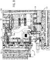
- the knockdown tines may each be positioned to straddle a reference line extending in the fore-aft direction from a forward-mounted tillage tool (e.g., shank or standard) so that the knockdown tines are first to hit the raised mounds of ground left behind from the tool.
- the channel 312 may be located at a forward end of the drawbar 300 or may run the full length of the drawbar 300, as shown.
- the saddle 310 has long sides 314 that fit along the transverse (i.e., vertical width) dimension of the fore-aft frame member 130 so that the saddle 310 overlaps the top and sides of the frame member.
- the sides 314 may be over-sized for certain frame members so that they may be used with other wider frame members.
- an upper wall 316 of the saddle 310 and in certain embodiments the entire drawbar 300, may be spaced from (above) the upper wall of the frame member.
- the drawbars 300 are used with larger frame members (e.g., 20,32 cm (8-inch) rather than 15,24 cm (6-inch) frame members)
- the upper wall 316 of the saddle 310 may rest on the top of the frame member.
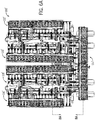
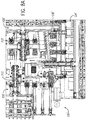
- the TI 100 has spike harrow attachments with anti-tangle brackets (as will be described) only at the main frame 114 and outer wing 110, 118 sections (the inner wing sections 112, 116 have chains).
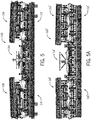
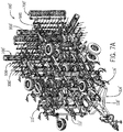
- the anti-tangle features are particularly useful for the outer wing sections 110, 118, which pivot about the hinge lines 122 approximately 180 degrees to a generally inverted orientation (see FIG. 5 ) during folding and unfolding, and which end up on at the center of the implement (between the inner wing sections) when in the folded configuration (see FIG. 7 ).
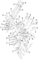
- the anti-tangle bracket assemblies 440 may also permit lateral movement of the ranks relative to the drawbar 300 to aid in residue flow between the spikes 420 and to reduce plugging.
- the lateral movement of the ranks is constrained (e.g., to a few inches toward each lateral side of the TI 100). This constrained lateral movement limits shifting of the spike harrow attachment 400 during folding and unfolding.
- each spike harrow attachment 400 is located in its pre-defined position and maintained there with little, or possibly even no, shifting during folding and unfolding.
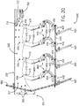
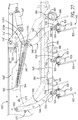
- the anti-tangle bracket assemblies 440 may have features, such as stop pins 470 in lobes 472 near the upper end of each upper pivot link 450, that cooperate and interfere with features, such as the lobes 460, formed in the sides of the drawbar 300, as shown in FIGS. 20 and 21 .
- a conventional drag chain 480 may be coupled to the drawbar 300 and the spike harrow attachment 400 so that the spikes 420 operate at their desired angle with the weight of the spike harrow attachment 400 on the spikes 420. When drag is set correctly, the anti-tangle bracket assemblies 440 will run partially tripped so that the spikes 420 move up and down to follow the ground.
- the ranks of tines may be mounted to one or more of the drawbars 300'.
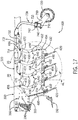
- the ranks may be mounted to two drawbars 300' each by one or more pivot links, such as pivot links 540 and 542 shown in the example embodiment.
- the pivot links 540, 542 permit the freedom of movement necessary for the tine harrow attachment 500 to perform as intended during operation so that the tines 520 penetrate the ground, but also to allow the ranks to trip so the tines 520 move out of engagement with the ground in the event excessively hard ground or an immovable object is encountered.
- the pivot links 540, 542 may also permit lateral movement of the ranks relative to the drawbar 300' to aid in residue flow between the tines 520 and to reduce plugging.
- the lateral movement of the ranks is constrained (e.g., to a few inches toward each lateral side of the TI 100').
- the term "spring” as used herein will be understood to include conventional coiled metal wire springs and piston-cylinder actuators.
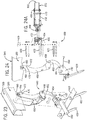
- the downforce spring 560 applies a biasing force to the pivot links 540, 542 in the clockwise direction (from the perspective of FIG. 25 ) to bias the ranks downward toward the ground to engage the teeth 522 of the tines 520 with the ground during operation.
- the pivot links 540, 542 pivot counter-clockwise (from the perspective of FIG. 25 ) to allow the ranks to trip rearward against the biasing force of the downforce spring 560 when an obstruction is encountered, after which the downforce spring 560 (and gravity) return the ranks to engage the tines 520 with the ground.
- the range of pivoting and the trip height may be the same or similar to that of the spike harrow attachment 400.
- the tine harrow attachment 500 may have mechanical stop features to limit the forward and/or rearward movement of the harrow ranks.
- forward and rearward stop pins 572 may be mounted to the drawbar 300' at suitable forward and rearward locations with respect to the forward pivot pin 552 for the forward pivot link 540. Protruding ends of the stop pins 572 cooperate, and are engaged by, opposite forward and rearward edges of the forward pivot link 540 to limit the pivot angle of the pivot links 540, 542, and thereby the harrow ranks.
- the forward stop pin 572 may be located to set the operating position (i.e., the non-tripped position) of the harrow ranks.
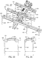
- the tines 520 may pivot rearward to a different angle at which the rank bars 510 engage the bumps 586 of the adjustment plate 584, as shown in FIGS. 29 and 30 , or the adjustment plate 584 may engage the rank bars 510 to set the tines 520 at a different tilt angle, as shown in FIG. 31 .
- An adjustment mechanism may be included to control the position of the adjustment plate 584 relative to the crossbar 530, and thus the pivot or tilt angle of the tines 520.
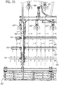
- the smoothing tines 520 of the third rearward rank straddle, and are centered on, another set of parallel reference lines S extending in the direction of travel D from the teeth 522 of the smoothing tines 520 of the fourth rearward rank.
- the third and fourth rearward ranks are offset from the forward-most rank in the lateral direction by an amount equal to one fourth of the spacing between the smoothing tines 520, or in the case of 22,86 cm (nine inch) smoothing tines, about 5,715 cm (2.25 inches).
Landscapes
- Life Sciences & Earth Sciences (AREA)
- Engineering & Computer Science (AREA)
- Mechanical Engineering (AREA)
- Soil Sciences (AREA)
- Environmental Sciences (AREA)
- Zoology (AREA)
- Soil Working Implements (AREA)
Claims (13)
- Herse attelée (400, 500) pour un outil de travail du sol, comprenant:une barre d'attelage (300, 300') de herse configurée pour pouvoir être montée sur un élément de châssis (130) d'un outil de travail du sol;au moins un rang de herse ayant une barre de rang (410, 510) supportant une pluralité d'outils de hersage;une liaison pivot (450, 452, 540, 542) accouplant de manière pivotante l'au moins un rang de herse à la barre d'attelage (300, 300') pour permettre à l'au moins un rang de herse de se déclencher en pivotant vers le haut en direction de la barre d'attelage (300, 300') depuis une position initiale dans laquelle l'au moins un rang de herse est le plus loin de la barre d'attelage (300, 300') ;un ressort d'appui (560) couplé à la barre d'attelage (300, 300') et configuré pour être dans un état de longueur fixe lorsque l'au moins un rang de herse est en position initiale et dans un état de longueur variable lorsque l'au moins un rang de herse est déclenché,un mécanisme de réglage avec une pluralité d'emplacements de réglage (570A - 570C),caractérisée en ce quele mécanisme de réglage comprend une broche de réglage (568) pouvant être montée sur chacun de la pluralité des emplacements de réglage (570A - 570C);le mécanisme de réglage accouplant le ressort d'appui (560) à l'un des au moins un rang de herse et la liaison pivot (450, 452, 540, 542) dans l'un de la pluralité des emplacements de réglage (570A - 570C) dans chacun desquels l'au moins un rang de herse est en position initiale et le ressort d'appui (560) est à l'état de longueur fixe;une première extrémité du ressort d'appui (560) étant montée sur la broche de réglage (568), etle ressort d'appui (560), à l'état de longueur variable, appliquant une force de rappel à l'au moins un rang de herse à l'écart de la barre d'attelage (300, 300'), et, à l'état de longueur fixe, la force de rappel étant enlevée.
- Herse attelée (400, 500) selon la revendication 1, dans laquelle la pluralité d'emplacements de réglage (570A - 570C) sont des ouvertures dans la liaison pivot (450, 452, 540, 542).
- Herse attelée (400, 500) selon la revendication 2, dans laquelle les ouvertures ont des centres disposés le long d'un rayon (R) s'étendant à partir d'un emplacement de montage d'une seconde extrémité du ressort d'appui (560) .
- Herse attelée (400, 500) selon l'une des revendications 1 à 3, caractérisée en ce que la liaison pivot (450, 452, 540, 542) est reliée à la barre d'attelage (300, 300') sur une extrémité et à l'au moins un rang de herse sur l'autre extrémité.
- Herse attelée (400, 500) selon l'une des revendications 1 à 4, dans laquelle il y a plusieurs rangs de herse et une barre transversale (530) reliée aux barres de rang (410, 510) des rangs de herse.
- Herse attelée (400, 500) selon la revendication 5, dans laquelle il y a plusieurs liaisons pivot (450, 452, 540, 542) espacées le long de la barre d'attelage (300, 300'), chacune étant reliée sur une extrémité à la barre d'attelage (300, 300') et sur une autre extrémité à l'une des barres transversales (530) et à l'une des barres de rang (410, 510).
- Herse attelée (400, 500) selon l'une des revendications 1 à 6, comprenant en outre un mécanisme de réglage d'angle d'inclinaison pour changer l'orientation angulaire de la pluralité d'outils par rapport à la barre d'attelage (300, 300').
- Herse attelée (400, 500) selon la revendication 7, dans laquelle le mécanisme de réglage de l'angle d'inclinaison comprend une plaque de réglage (584) montée sur la barre transversale (530); et
la plaque de réglage (584) comprenant des premier et second lobes de protubérance (586) qui s'engagent dans les barres de rang (410, 510) des rangs de herse pour régler l'orientation angulaire de la pluralité des outils de hersage. - Herse attelée (400, 500) selon la revendication 8, comprenant en outre un second mécanisme de réglage accouplant la plaque de réglage (584) à la barre transversale (530) dans l'une parmi une pluralité d'orientations de montage avant-arrière.
- Herse attelée (400, 500) selon la revendication 9, dans laquelle le second mécanisme de réglage comprend une seconde broche de réglage (588) reçue dans des ouvertures alignées (590) dans la barre transversale (530) et la plaque de réglage (584).
- Herse attelée (400, 500) selon l'une des revendications 1 à 10, dans laquelle la pluralité d'outils de hersage sont des pointes (520, 620); dans laquelle il existe une pluralité de rangs comprenant un rang avant ayant une pluralité de pointes démontables (620) et un ou plusieurs rangs arrière placés en arrière du rang avant par rapport à une direction de déplacement ayant une pluralité de pointes de polissage (520); et
les dents des pointes démontables (620) étant au moins l'une des dents de polissage (520), plus épaisses et espacées plus largement que les dents de celles-ci. - Herse attelée (400, 500) selon la revendication 11, dans laquelle l'espacement entre les dents des pointes démontables (620) est au moins cinquante pour cent plus large que l'espacement entre les dents des pointes de polissage (520); et
les dents des pointes démontables (620) étant au moins cinquante pour cent plus épaisses que les dents des pointes de polissage (520). - Outil de travail du sol, comprenant:
un châssis d'outil; et une herse attelée (400, 500) selon l'une des revendications 1 à 12.
Applications Claiming Priority (2)
| Application Number | Priority Date | Filing Date | Title |
|---|---|---|---|
| US201562222564P | 2015-09-23 | 2015-09-23 | |
| US15/243,739 US10327373B2 (en) | 2015-09-23 | 2016-08-22 | Harrow downforce adjustment |
Publications (2)
| Publication Number | Publication Date |
|---|---|
| EP3146820A1 EP3146820A1 (fr) | 2017-03-29 |
| EP3146820B1 true EP3146820B1 (fr) | 2019-02-27 |
Family
ID=56979424
Family Applications (1)
| Application Number | Title | Priority Date | Filing Date |
|---|---|---|---|
| EP16189705.3A Active EP3146820B1 (fr) | 2015-09-23 | 2016-09-20 | Herse atelée et outil de travail du sol avec un tel attelage |
Country Status (2)
| Country | Link |
|---|---|
| US (1) | US10327373B2 (fr) |
| EP (1) | EP3146820B1 (fr) |
Cited By (1)
| Publication number | Priority date | Publication date | Assignee | Title |
|---|---|---|---|---|
| EP4066608A1 (fr) | 2021-04-01 | 2022-10-05 | Horsch Maschinen GmbH | Dispositif de traitement du sol |
Families Citing this family (18)
| Publication number | Priority date | Publication date | Assignee | Title |
|---|---|---|---|---|
| US20160073572A1 (en) * | 2014-09-12 | 2016-03-17 | Bigham Brothers, Inc. | Adjustable multiple row agricultural implement |
| US10117373B2 (en) * | 2015-02-10 | 2018-11-06 | Salford Group Inc. | Tine harrow |
| US10342171B2 (en) * | 2016-10-19 | 2019-07-09 | Cnh Industrial America Llc | System for adjusting smoothing tools of a harrow using a linear actuator |
| US10448554B2 (en) * | 2016-10-19 | 2019-10-22 | Cnh Industrial America Llc | Electronic control system for adjusting smoothing tools of a harrow |
| US10368471B2 (en) * | 2016-10-28 | 2019-08-06 | Cnh Industrial America Llc | System for equalizing pressure on smoothing tools of a harrow |
| US10542658B2 (en) * | 2016-11-07 | 2020-01-28 | Cnh Industrial America Llc | System for adjusting down pressure loads on ground engaging elements of an agricultural implement |
| US10645860B2 (en) * | 2017-03-31 | 2020-05-12 | Cnh Industrial America Llc | Seedbed condition monitoring system with a seedbed surface detection assembly |
| AT15980U1 (de) * | 2017-04-18 | 2018-10-15 | Juergen Schoels | Bodenbearbeitungsgerät |
| US10602653B2 (en) * | 2017-10-25 | 2020-03-31 | Cnh Industrial Canada, Ltd. | System and method for controlling the orientation of ground engaging elements on an agricultural implement |
| US10561053B1 (en) | 2018-08-15 | 2020-02-18 | Deere & Company | Frame assembly and actuator arrangement for agricultural imglements |
| US10660254B2 (en) | 2018-08-15 | 2020-05-26 | Deere & Company | Frame and leveling assembly for agricultural implement |
| DK180096B1 (en) * | 2018-10-11 | 2020-04-29 | GAMMELSKOV SERVICE TEKNIK ApS | Rotary hoe arrangement and the use of a rotary hoe arrangement for hoeing |
| US11006571B2 (en) * | 2019-05-09 | 2021-05-18 | Cnh Industrial America Llc | Floatation springs attached to adjustable skid shoes |
| US11445656B2 (en) * | 2019-11-26 | 2022-09-20 | Cnh Industrial America Llc | System and method for preventing material accumulation relative to ground engaging tools of an agricultural implement |
| NL2031182B1 (en) | 2021-03-31 | 2023-11-10 | Man@Machine B V | A hoe attachment, a hoe tool, a hoe and harrow tool, an agricultural device, and a method for using an agricultural device |
| CN114342585B (zh) * | 2022-01-06 | 2023-08-29 | 吉林省农业机械研究院 | 一种玉米种床整理联合作业机 |
| US12543618B2 (en) | 2022-12-19 | 2026-02-10 | Cnh Industrial America Llc | Retractable spike tooth harrow for large field cultivator |
| US12471515B2 (en) * | 2023-03-23 | 2025-11-18 | Cnh Industrial America Llc | Agricultural implement with a support arm for reducing vibrations transmitted to sensors |
Family Cites Families (24)
| Publication number | Priority date | Publication date | Assignee | Title |
|---|---|---|---|---|
| US3640345A (en) | 1969-09-08 | 1972-02-08 | Noble Mfg Co | Foldable harrow cart |
| NL7007690A (fr) * | 1970-05-28 | 1971-11-30 | ||
| US3774694A (en) * | 1971-10-20 | 1973-11-27 | R Gates | Flexible harrow device |
| US4042045A (en) | 1975-06-23 | 1977-08-16 | Kent Manufacturing Co., Inc. | Multiple section farm implement with biased swinging arm structure for attaching reinforcing member to main frame |
| IT1095793B (it) | 1977-11-04 | 1985-08-17 | Biasotto Livio | Erpice a denti anteriori di erpicatura con rulli posteriori di livellamento e lavorazione terreno |
| US4306732A (en) | 1979-12-10 | 1981-12-22 | J. E. Love Company | Depth control for agricultural implement |
| US4342366A (en) * | 1981-01-26 | 1982-08-03 | International Harvester Co. | Soil mulcher |
| US6164386A (en) | 1999-04-02 | 2000-12-26 | Delaurier; Ronald T. | Harrow |
| CA2329462A1 (fr) | 2000-12-20 | 2002-06-20 | Wilfred J. Degelman | Herse portee a dents rigides avec dispositif de levage |
| US6578640B1 (en) | 2001-02-20 | 2003-06-17 | Ohlman Engineering | Apparatus and method for preparing agricultural ground for planting |
| US6626246B2 (en) | 2001-04-05 | 2003-09-30 | Case, Llc | Tillage implement with one point pin angle adjustment |
| US6896068B2 (en) | 2001-04-05 | 2005-05-24 | Cnh America Llc | Tillage implement with indexed harrow |
| US6612381B2 (en) | 2001-11-06 | 2003-09-02 | Case, Llc | Seedbed preparation implement having rotary disc with adjustable gang angle |
| US6688405B2 (en) | 2002-01-16 | 2004-02-10 | Deere & Company | Simplified adjustable tine harrow assembly |
| US6926093B1 (en) | 2003-08-21 | 2005-08-09 | Krause Plow Corporation, Inc. | Mechanism for mounting a soil leveling device |
| US7766093B2 (en) | 2006-08-29 | 2010-08-03 | Deere & Company | Hydraulic lift rolling basket structure for a tillage implement |
| US8047299B2 (en) | 2006-12-14 | 2011-11-01 | Cnh America Llc | Crop residue and soil conditioning agricultural implement |
| US7918285B1 (en) | 2010-04-19 | 2011-04-05 | Deere & Company | Implement with active wing down force and wing lift sequencing |
| US20120298386A1 (en) | 2011-05-27 | 2012-11-29 | Unverferth Manufacturing Company Inc. | Tool free adjustable tension leveling harrow bar |
| US20140158386A1 (en) | 2012-12-06 | 2014-06-12 | Deere & Company | Folding earth-working tool attachment of an agricultural implement |
| CA2845352C (fr) | 2013-03-11 | 2019-12-03 | Salford Group Inc. | Herse rotative a commande hydraulique pour appareil et systeme de labourage |
| US9474197B2 (en) | 2013-03-15 | 2016-10-25 | Mcfarlane Manufacturing Co., Inc. | Universal custom agricultural field preparation implement |
| US9609796B2 (en) * | 2013-10-17 | 2017-04-04 | Abi Attachments, Inc. | Grading tools for work machines and operation thereof |
| US9872422B2 (en) | 2013-12-11 | 2018-01-23 | Cnh Industrial America Llc | Flexible wing sections for a field cultivator |
-
2016
- 2016-08-22 US US15/243,739 patent/US10327373B2/en active Active
- 2016-09-20 EP EP16189705.3A patent/EP3146820B1/fr active Active
Non-Patent Citations (1)
| Title |
|---|
| None * |
Cited By (1)
| Publication number | Priority date | Publication date | Assignee | Title |
|---|---|---|---|---|
| EP4066608A1 (fr) | 2021-04-01 | 2022-10-05 | Horsch Maschinen GmbH | Dispositif de traitement du sol |
Also Published As
| Publication number | Publication date |
|---|---|
| US20170079190A1 (en) | 2017-03-23 |
| US10327373B2 (en) | 2019-06-25 |
| EP3146820A1 (fr) | 2017-03-29 |
Similar Documents
| Publication | Publication Date | Title |
|---|---|---|
| CA3228108C (fr) | Accessoire de labourage a decalage de train intra-aile | |
| EP3146820B1 (fr) | Herse atelée et outil de travail du sol avec un tel attelage | |
| US10045475B2 (en) | Roller basket finishing attachment | |
| EP3146819B1 (fr) | Herse attelée et outil de travail du sol avec un tel attelage | |
| EP3122168B1 (fr) | Appareil de travail du sol comprenant un dispositif d'étrillage et d'aplanissement | |
| US20160262299A1 (en) | Agricultural implement having diverse hitch and gang operation modes | |
| WO1999002027A1 (fr) | Instrument aratoire avec disques a reglage instantane de l'angle et de la profondeur | |
| US10561053B1 (en) | Frame assembly and actuator arrangement for agricultural imglements | |
| US4318444A (en) | Telescoping hinge member on rearwardly folding tool bar | |
| US9955621B2 (en) | Front fold implement frame with pivotal draft link connection | |
| US11582894B2 (en) | Frame and leveling assembly for agricultural implement | |
| US8413737B2 (en) | Implement and assembly for carrying out operations on an agricultural land | |
| US10251323B2 (en) | Agricultural tillage implement with soil finishing system having multiple bar harrow and hydraulic down pressure for finishing tool | |
| EP3620038A1 (fr) | Cultivateur tracté | |
| WO2006004538A1 (fr) | Unite dent de travail des sols pour systeme de travail des sols |
Legal Events
| Date | Code | Title | Description |
|---|---|---|---|
| PUAI | Public reference made under article 153(3) epc to a published international application that has entered the european phase |
Free format text: ORIGINAL CODE: 0009012 |
|
| STAA | Information on the status of an ep patent application or granted ep patent |
Free format text: STATUS: THE APPLICATION HAS BEEN PUBLISHED |
|
| AK | Designated contracting states |
Kind code of ref document: A1 Designated state(s): AL AT BE BG CH CY CZ DE DK EE ES FI FR GB GR HR HU IE IS IT LI LT LU LV MC MK MT NL NO PL PT RO RS SE SI SK SM TR |
|
| AX | Request for extension of the european patent |
Extension state: BA ME |
|
| STAA | Information on the status of an ep patent application or granted ep patent |
Free format text: STATUS: REQUEST FOR EXAMINATION WAS MADE |
|
| 17P | Request for examination filed |
Effective date: 20170929 |
|
| RBV | Designated contracting states (corrected) |
Designated state(s): AL AT BE BG CH CY CZ DE DK EE ES FI FR GB GR HR HU IE IS IT LI LT LU LV MC MK MT NL NO PL PT RO RS SE SI SK SM TR |
|
| GRAP | Despatch of communication of intention to grant a patent |
Free format text: ORIGINAL CODE: EPIDOSNIGR1 |
|
| STAA | Information on the status of an ep patent application or granted ep patent |
Free format text: STATUS: GRANT OF PATENT IS INTENDED |
|
| RIC1 | Information provided on ipc code assigned before grant |
Ipc: A01B 19/04 20060101AFI20180813BHEP Ipc: A01B 49/02 20060101ALI20180813BHEP Ipc: A01B 23/04 20060101ALI20180813BHEP |
|
| INTG | Intention to grant announced |
Effective date: 20180917 |
|
| GRAS | Grant fee paid |
Free format text: ORIGINAL CODE: EPIDOSNIGR3 |
|
| GRAA | (expected) grant |
Free format text: ORIGINAL CODE: 0009210 |
|
| STAA | Information on the status of an ep patent application or granted ep patent |
Free format text: STATUS: THE PATENT HAS BEEN GRANTED |
|
| AK | Designated contracting states |
Kind code of ref document: B1 Designated state(s): AL AT BE BG CH CY CZ DE DK EE ES FI FR GB GR HR HU IE IS IT LI LT LU LV MC MK MT NL NO PL PT RO RS SE SI SK SM TR |
|
| REG | Reference to a national code |
Ref country code: GB Ref legal event code: FG4D |
|
| REG | Reference to a national code |
Ref country code: CH Ref legal event code: EP |
|
| REG | Reference to a national code |
Ref country code: AT Ref legal event code: REF Ref document number: 1099985 Country of ref document: AT Kind code of ref document: T Effective date: 20190315 |
|
| REG | Reference to a national code |
Ref country code: IE Ref legal event code: FG4D |
|
| REG | Reference to a national code |
Ref country code: DE Ref legal event code: R096 Ref document number: 602016010299 Country of ref document: DE |
|
| REG | Reference to a national code |
Ref country code: NL Ref legal event code: MP Effective date: 20190227 |
|
| REG | Reference to a national code |
Ref country code: LT Ref legal event code: MG4D |
|
| PG25 | Lapsed in a contracting state [announced via postgrant information from national office to epo] |
Ref country code: FI Free format text: LAPSE BECAUSE OF FAILURE TO SUBMIT A TRANSLATION OF THE DESCRIPTION OR TO PAY THE FEE WITHIN THE PRESCRIBED TIME-LIMIT Effective date: 20190227 Ref country code: NO Free format text: LAPSE BECAUSE OF FAILURE TO SUBMIT A TRANSLATION OF THE DESCRIPTION OR TO PAY THE FEE WITHIN THE PRESCRIBED TIME-LIMIT Effective date: 20190527 Ref country code: PT Free format text: LAPSE BECAUSE OF FAILURE TO SUBMIT A TRANSLATION OF THE DESCRIPTION OR TO PAY THE FEE WITHIN THE PRESCRIBED TIME-LIMIT Effective date: 20190627 Ref country code: SE Free format text: LAPSE BECAUSE OF FAILURE TO SUBMIT A TRANSLATION OF THE DESCRIPTION OR TO PAY THE FEE WITHIN THE PRESCRIBED TIME-LIMIT Effective date: 20190227 Ref country code: LT Free format text: LAPSE BECAUSE OF FAILURE TO SUBMIT A TRANSLATION OF THE DESCRIPTION OR TO PAY THE FEE WITHIN THE PRESCRIBED TIME-LIMIT Effective date: 20190227 Ref country code: NL Free format text: LAPSE BECAUSE OF FAILURE TO SUBMIT A TRANSLATION OF THE DESCRIPTION OR TO PAY THE FEE WITHIN THE PRESCRIBED TIME-LIMIT Effective date: 20190227 |
|
| PG25 | Lapsed in a contracting state [announced via postgrant information from national office to epo] |
Ref country code: LV Free format text: LAPSE BECAUSE OF FAILURE TO SUBMIT A TRANSLATION OF THE DESCRIPTION OR TO PAY THE FEE WITHIN THE PRESCRIBED TIME-LIMIT Effective date: 20190227 Ref country code: HR Free format text: LAPSE BECAUSE OF FAILURE TO SUBMIT A TRANSLATION OF THE DESCRIPTION OR TO PAY THE FEE WITHIN THE PRESCRIBED TIME-LIMIT Effective date: 20190227 Ref country code: GR Free format text: LAPSE BECAUSE OF FAILURE TO SUBMIT A TRANSLATION OF THE DESCRIPTION OR TO PAY THE FEE WITHIN THE PRESCRIBED TIME-LIMIT Effective date: 20190528 Ref country code: IS Free format text: LAPSE BECAUSE OF FAILURE TO SUBMIT A TRANSLATION OF THE DESCRIPTION OR TO PAY THE FEE WITHIN THE PRESCRIBED TIME-LIMIT Effective date: 20190627 Ref country code: RS Free format text: LAPSE BECAUSE OF FAILURE TO SUBMIT A TRANSLATION OF THE DESCRIPTION OR TO PAY THE FEE WITHIN THE PRESCRIBED TIME-LIMIT Effective date: 20190227 Ref country code: BG Free format text: LAPSE BECAUSE OF FAILURE TO SUBMIT A TRANSLATION OF THE DESCRIPTION OR TO PAY THE FEE WITHIN THE PRESCRIBED TIME-LIMIT Effective date: 20190527 |
|
| REG | Reference to a national code |
Ref country code: AT Ref legal event code: MK05 Ref document number: 1099985 Country of ref document: AT Kind code of ref document: T Effective date: 20190227 |
|
| PG25 | Lapsed in a contracting state [announced via postgrant information from national office to epo] |
Ref country code: ES Free format text: LAPSE BECAUSE OF FAILURE TO SUBMIT A TRANSLATION OF THE DESCRIPTION OR TO PAY THE FEE WITHIN THE PRESCRIBED TIME-LIMIT Effective date: 20190227 Ref country code: DK Free format text: LAPSE BECAUSE OF FAILURE TO SUBMIT A TRANSLATION OF THE DESCRIPTION OR TO PAY THE FEE WITHIN THE PRESCRIBED TIME-LIMIT Effective date: 20190227 Ref country code: EE Free format text: LAPSE BECAUSE OF FAILURE TO SUBMIT A TRANSLATION OF THE DESCRIPTION OR TO PAY THE FEE WITHIN THE PRESCRIBED TIME-LIMIT Effective date: 20190227 Ref country code: RO Free format text: LAPSE BECAUSE OF FAILURE TO SUBMIT A TRANSLATION OF THE DESCRIPTION OR TO PAY THE FEE WITHIN THE PRESCRIBED TIME-LIMIT Effective date: 20190227 Ref country code: IT Free format text: LAPSE BECAUSE OF FAILURE TO SUBMIT A TRANSLATION OF THE DESCRIPTION OR TO PAY THE FEE WITHIN THE PRESCRIBED TIME-LIMIT Effective date: 20190227 Ref country code: CZ Free format text: LAPSE BECAUSE OF FAILURE TO SUBMIT A TRANSLATION OF THE DESCRIPTION OR TO PAY THE FEE WITHIN THE PRESCRIBED TIME-LIMIT Effective date: 20190227 Ref country code: AL Free format text: LAPSE BECAUSE OF FAILURE TO SUBMIT A TRANSLATION OF THE DESCRIPTION OR TO PAY THE FEE WITHIN THE PRESCRIBED TIME-LIMIT Effective date: 20190227 Ref country code: SK Free format text: LAPSE BECAUSE OF FAILURE TO SUBMIT A TRANSLATION OF THE DESCRIPTION OR TO PAY THE FEE WITHIN THE PRESCRIBED TIME-LIMIT Effective date: 20190227 |
|
| REG | Reference to a national code |
Ref country code: DE Ref legal event code: R097 Ref document number: 602016010299 Country of ref document: DE |
|
| PG25 | Lapsed in a contracting state [announced via postgrant information from national office to epo] |
Ref country code: PL Free format text: LAPSE BECAUSE OF FAILURE TO SUBMIT A TRANSLATION OF THE DESCRIPTION OR TO PAY THE FEE WITHIN THE PRESCRIBED TIME-LIMIT Effective date: 20190227 Ref country code: SM Free format text: LAPSE BECAUSE OF FAILURE TO SUBMIT A TRANSLATION OF THE DESCRIPTION OR TO PAY THE FEE WITHIN THE PRESCRIBED TIME-LIMIT Effective date: 20190227 |
|
| PG25 | Lapsed in a contracting state [announced via postgrant information from national office to epo] |
Ref country code: AT Free format text: LAPSE BECAUSE OF FAILURE TO SUBMIT A TRANSLATION OF THE DESCRIPTION OR TO PAY THE FEE WITHIN THE PRESCRIBED TIME-LIMIT Effective date: 20190227 |
|
| PLBE | No opposition filed within time limit |
Free format text: ORIGINAL CODE: 0009261 |
|
| STAA | Information on the status of an ep patent application or granted ep patent |
Free format text: STATUS: NO OPPOSITION FILED WITHIN TIME LIMIT |
|
| 26N | No opposition filed |
Effective date: 20191128 |
|
| PG25 | Lapsed in a contracting state [announced via postgrant information from national office to epo] |
Ref country code: SI Free format text: LAPSE BECAUSE OF FAILURE TO SUBMIT A TRANSLATION OF THE DESCRIPTION OR TO PAY THE FEE WITHIN THE PRESCRIBED TIME-LIMIT Effective date: 20190227 |
|
| PG25 | Lapsed in a contracting state [announced via postgrant information from national office to epo] |
Ref country code: TR Free format text: LAPSE BECAUSE OF FAILURE TO SUBMIT A TRANSLATION OF THE DESCRIPTION OR TO PAY THE FEE WITHIN THE PRESCRIBED TIME-LIMIT Effective date: 20190227 |
|
| PG25 | Lapsed in a contracting state [announced via postgrant information from national office to epo] |
Ref country code: MC Free format text: LAPSE BECAUSE OF FAILURE TO SUBMIT A TRANSLATION OF THE DESCRIPTION OR TO PAY THE FEE WITHIN THE PRESCRIBED TIME-LIMIT Effective date: 20190227 |
|
| REG | Reference to a national code |
Ref country code: CH Ref legal event code: PL |
|
| PG25 | Lapsed in a contracting state [announced via postgrant information from national office to epo] |
Ref country code: CH Free format text: LAPSE BECAUSE OF NON-PAYMENT OF DUE FEES Effective date: 20190930 Ref country code: LU Free format text: LAPSE BECAUSE OF NON-PAYMENT OF DUE FEES Effective date: 20190920 Ref country code: IE Free format text: LAPSE BECAUSE OF NON-PAYMENT OF DUE FEES Effective date: 20190920 Ref country code: LI Free format text: LAPSE BECAUSE OF NON-PAYMENT OF DUE FEES Effective date: 20190930 |
|
| REG | Reference to a national code |
Ref country code: BE Ref legal event code: MM Effective date: 20190930 |
|
| PG25 | Lapsed in a contracting state [announced via postgrant information from national office to epo] |
Ref country code: BE Free format text: LAPSE BECAUSE OF NON-PAYMENT OF DUE FEES Effective date: 20190930 |
|
| GBPC | Gb: european patent ceased through non-payment of renewal fee |
Effective date: 20200920 |
|
| PG25 | Lapsed in a contracting state [announced via postgrant information from national office to epo] |
Ref country code: CY Free format text: LAPSE BECAUSE OF FAILURE TO SUBMIT A TRANSLATION OF THE DESCRIPTION OR TO PAY THE FEE WITHIN THE PRESCRIBED TIME-LIMIT Effective date: 20190227 |
|
| PG25 | Lapsed in a contracting state [announced via postgrant information from national office to epo] |
Ref country code: HU Free format text: LAPSE BECAUSE OF FAILURE TO SUBMIT A TRANSLATION OF THE DESCRIPTION OR TO PAY THE FEE WITHIN THE PRESCRIBED TIME-LIMIT; INVALID AB INITIO Effective date: 20160920 Ref country code: MT Free format text: LAPSE BECAUSE OF FAILURE TO SUBMIT A TRANSLATION OF THE DESCRIPTION OR TO PAY THE FEE WITHIN THE PRESCRIBED TIME-LIMIT Effective date: 20190227 |
|
| PG25 | Lapsed in a contracting state [announced via postgrant information from national office to epo] |
Ref country code: GB Free format text: LAPSE BECAUSE OF NON-PAYMENT OF DUE FEES Effective date: 20200920 |
|
| PG25 | Lapsed in a contracting state [announced via postgrant information from national office to epo] |
Ref country code: MK Free format text: LAPSE BECAUSE OF FAILURE TO SUBMIT A TRANSLATION OF THE DESCRIPTION OR TO PAY THE FEE WITHIN THE PRESCRIBED TIME-LIMIT Effective date: 20190227 |
|
| PGFP | Annual fee paid to national office [announced via postgrant information from national office to epo] |
Ref country code: DE Payment date: 20250820 Year of fee payment: 10 |
|
| PGFP | Annual fee paid to national office [announced via postgrant information from national office to epo] |
Ref country code: FR Payment date: 20250925 Year of fee payment: 10 |