EP3146898B1 - Quantum-dot spectrometers for use in biomedical devices and methods of use - Google Patents
Quantum-dot spectrometers for use in biomedical devices and methods of use Download PDFInfo
- Publication number
- EP3146898B1 EP3146898B1 EP16190406.5A EP16190406A EP3146898B1 EP 3146898 B1 EP3146898 B1 EP 3146898B1 EP 16190406 A EP16190406 A EP 16190406A EP 3146898 B1 EP3146898 B1 EP 3146898B1
- Authority
- EP
- European Patent Office
- Prior art keywords
- quantum
- dot
- biomedical device
- sample
- biomedical
- Prior art date
- Legal status (The legal status is an assumption and is not a legal conclusion. Google has not performed a legal analysis and makes no representation as to the accuracy of the status listed.)
- Not-in-force
Links
- 239000002096 quantum dot Substances 0.000 title claims description 191
- 238000000034 method Methods 0.000 title claims description 39
- 239000012530 fluid Substances 0.000 claims description 78
- 239000012491 analyte Substances 0.000 claims description 67
- 238000004458 analytical method Methods 0.000 claims description 38
- 239000006187 pill Substances 0.000 claims description 28
- 238000012545 processing Methods 0.000 claims description 27
- 230000003595 spectral effect Effects 0.000 claims description 26
- 239000003814 drug Substances 0.000 claims description 24
- 239000011148 porous material Substances 0.000 claims description 21
- 230000006870 function Effects 0.000 claims description 17
- 230000007246 mechanism Effects 0.000 claims description 13
- 239000003153 chemical reaction reagent Substances 0.000 claims description 12
- 238000005086 pumping Methods 0.000 claims description 12
- 238000005538 encapsulation Methods 0.000 claims description 11
- 239000003792 electrolyte Substances 0.000 claims description 8
- 238000002835 absorbance Methods 0.000 claims description 7
- 210000001124 body fluid Anatomy 0.000 claims description 5
- 230000002596 correlated effect Effects 0.000 claims description 4
- 239000000523 sample Substances 0.000 description 91
- 239000010410 layer Substances 0.000 description 53
- 239000000975 dye Substances 0.000 description 30
- WQZGKKKJIJFFOK-GASJEMHNSA-N Glucose Natural products OC[C@H]1OC(O)[C@H](O)[C@@H](O)[C@@H]1O WQZGKKKJIJFFOK-GASJEMHNSA-N 0.000 description 21
- 239000008103 glucose Substances 0.000 description 21
- 239000000463 material Substances 0.000 description 20
- 238000004891 communication Methods 0.000 description 17
- 238000002032 lab-on-a-chip Methods 0.000 description 16
- 238000010791 quenching Methods 0.000 description 16
- 230000000171 quenching effect Effects 0.000 description 15
- 239000000090 biomarker Substances 0.000 description 14
- 238000005516 engineering process Methods 0.000 description 13
- 238000004611 spectroscopical analysis Methods 0.000 description 13
- 210000001508 eye Anatomy 0.000 description 12
- 230000008859 change Effects 0.000 description 11
- 230000004044 response Effects 0.000 description 11
- 238000003860 storage Methods 0.000 description 11
- 239000000126 substance Substances 0.000 description 10
- 238000010521 absorption reaction Methods 0.000 description 9
- 238000005259 measurement Methods 0.000 description 9
- 239000000203 mixture Substances 0.000 description 9
- 238000001327 Förster resonance energy transfer Methods 0.000 description 8
- 230000005284 excitation Effects 0.000 description 8
- 238000012544 monitoring process Methods 0.000 description 8
- 230000003287 optical effect Effects 0.000 description 8
- 230000001276 controlling effect Effects 0.000 description 7
- 239000000017 hydrogel Substances 0.000 description 7
- 239000000758 substrate Substances 0.000 description 7
- 238000001514 detection method Methods 0.000 description 6
- 230000000694 effects Effects 0.000 description 6
- 239000007788 liquid Substances 0.000 description 6
- 238000001228 spectrum Methods 0.000 description 6
- 230000002159 abnormal effect Effects 0.000 description 5
- 230000009471 action Effects 0.000 description 5
- 239000011248 coating agent Substances 0.000 description 5
- 238000000576 coating method Methods 0.000 description 5
- 239000013078 crystal Substances 0.000 description 5
- 238000013461 design Methods 0.000 description 5
- 238000010586 diagram Methods 0.000 description 5
- 210000003722 extracellular fluid Anatomy 0.000 description 5
- 230000003993 interaction Effects 0.000 description 5
- -1 poly(2-(6-cyano-6'-methylheptyloxy)- 1,4-phenylene) Polymers 0.000 description 5
- 239000004065 semiconductor Substances 0.000 description 5
- 239000000243 solution Substances 0.000 description 5
- OKTJSMMVPCPJKN-UHFFFAOYSA-N Carbon Chemical compound [C] OKTJSMMVPCPJKN-UHFFFAOYSA-N 0.000 description 4
- 230000005540 biological transmission Effects 0.000 description 4
- 210000004027 cell Anatomy 0.000 description 4
- 238000006243 chemical reaction Methods 0.000 description 4
- 239000004020 conductor Substances 0.000 description 4
- DMBHHRLKUKUOEG-UHFFFAOYSA-N diphenylamine Chemical compound C=1C=CC=CC=1NC1=CC=CC=C1 DMBHHRLKUKUOEG-UHFFFAOYSA-N 0.000 description 4
- 238000004519 manufacturing process Methods 0.000 description 4
- 239000012528 membrane Substances 0.000 description 4
- 108090000623 proteins and genes Proteins 0.000 description 4
- 102000004169 proteins and genes Human genes 0.000 description 4
- 238000005070 sampling Methods 0.000 description 4
- 238000010183 spectrum analysis Methods 0.000 description 4
- 239000010409 thin film Substances 0.000 description 4
- 238000012546 transfer Methods 0.000 description 4
- 239000002699 waste material Substances 0.000 description 4
- 108010015776 Glucose oxidase Proteins 0.000 description 3
- 239000004366 Glucose oxidase Substances 0.000 description 3
- BQCADISMDOOEFD-UHFFFAOYSA-N Silver Chemical compound [Ag] BQCADISMDOOEFD-UHFFFAOYSA-N 0.000 description 3
- 239000013060 biological fluid Substances 0.000 description 3
- 239000008280 blood Substances 0.000 description 3
- 210000004369 blood Anatomy 0.000 description 3
- 229910052799 carbon Inorganic materials 0.000 description 3
- 230000000536 complexating effect Effects 0.000 description 3
- 239000000470 constituent Substances 0.000 description 3
- 229940079593 drug Drugs 0.000 description 3
- 229940116332 glucose oxidase Drugs 0.000 description 3
- 235000019420 glucose oxidase Nutrition 0.000 description 3
- PCHJSUWPFVWCPO-UHFFFAOYSA-N gold Chemical compound [Au] PCHJSUWPFVWCPO-UHFFFAOYSA-N 0.000 description 3
- 229910052737 gold Inorganic materials 0.000 description 3
- 239000010931 gold Substances 0.000 description 3
- 239000002159 nanocrystal Substances 0.000 description 3
- 229920000642 polymer Polymers 0.000 description 3
- 239000000047 product Substances 0.000 description 3
- 229910052709 silver Inorganic materials 0.000 description 3
- 239000004332 silver Substances 0.000 description 3
- 238000011282 treatment Methods 0.000 description 3
- XLYOFNOQVPJJNP-UHFFFAOYSA-N water Substances O XLYOFNOQVPJJNP-UHFFFAOYSA-N 0.000 description 3
- OYPRJOBELJOOCE-UHFFFAOYSA-N Calcium Chemical compound [Ca] OYPRJOBELJOOCE-UHFFFAOYSA-N 0.000 description 2
- RYGMFSIKBFXOCR-UHFFFAOYSA-N Copper Chemical compound [Cu] RYGMFSIKBFXOCR-UHFFFAOYSA-N 0.000 description 2
- GPXJNWSHGFTCBW-UHFFFAOYSA-N Indium phosphide Chemical compound [In]#P GPXJNWSHGFTCBW-UHFFFAOYSA-N 0.000 description 2
- XEEYBQQBJWHFJM-UHFFFAOYSA-N Iron Chemical compound [Fe] XEEYBQQBJWHFJM-UHFFFAOYSA-N 0.000 description 2
- FYYHWMGAXLPEAU-UHFFFAOYSA-N Magnesium Chemical compound [Mg] FYYHWMGAXLPEAU-UHFFFAOYSA-N 0.000 description 2
- KDLHZDBZIXYQEI-UHFFFAOYSA-N Palladium Chemical compound [Pd] KDLHZDBZIXYQEI-UHFFFAOYSA-N 0.000 description 2
- XUIMIQQOPSSXEZ-UHFFFAOYSA-N Silicon Chemical compound [Si] XUIMIQQOPSSXEZ-UHFFFAOYSA-N 0.000 description 2
- 239000005083 Zinc sulfide Substances 0.000 description 2
- 230000004913 activation Effects 0.000 description 2
- 238000003491 array Methods 0.000 description 2
- 230000008901 benefit Effects 0.000 description 2
- 239000011230 binding agent Substances 0.000 description 2
- 229910052791 calcium Inorganic materials 0.000 description 2
- 239000011575 calcium Substances 0.000 description 2
- 238000004364 calculation method Methods 0.000 description 2
- 239000007795 chemical reaction product Substances 0.000 description 2
- 150000001875 compounds Chemical class 0.000 description 2
- 229910052802 copper Inorganic materials 0.000 description 2
- 239000010949 copper Substances 0.000 description 2
- 230000000875 corresponding effect Effects 0.000 description 2
- 238000011161 development Methods 0.000 description 2
- 230000018109 developmental process Effects 0.000 description 2
- ZUOUZKKEUPVFJK-UHFFFAOYSA-N diphenyl Chemical compound C1=CC=CC=C1C1=CC=CC=C1 ZUOUZKKEUPVFJK-UHFFFAOYSA-N 0.000 description 2
- 201000010099 disease Diseases 0.000 description 2
- 208000037265 diseases, disorders, signs and symptoms Diseases 0.000 description 2
- 230000001747 exhibiting effect Effects 0.000 description 2
- 239000000945 filler Substances 0.000 description 2
- 239000007850 fluorescent dye Substances 0.000 description 2
- 230000002496 gastric effect Effects 0.000 description 2
- 230000005525 hole transport Effects 0.000 description 2
- 229910052749 magnesium Inorganic materials 0.000 description 2
- 239000011777 magnesium Substances 0.000 description 2
- 239000011159 matrix material Substances 0.000 description 2
- 229910052751 metal Inorganic materials 0.000 description 2
- 239000002184 metal Substances 0.000 description 2
- 229910044991 metal oxide Inorganic materials 0.000 description 2
- 150000004706 metal oxides Chemical class 0.000 description 2
- 238000004377 microelectronic Methods 0.000 description 2
- 239000002105 nanoparticle Substances 0.000 description 2
- 229910000510 noble metal Inorganic materials 0.000 description 2
- 230000010363 phase shift Effects 0.000 description 2
- BASFCYQUMIYNBI-UHFFFAOYSA-N platinum Chemical compound [Pt] BASFCYQUMIYNBI-UHFFFAOYSA-N 0.000 description 2
- 230000008569 process Effects 0.000 description 2
- 230000005855 radiation Effects 0.000 description 2
- 230000004276 retinal vascularization Effects 0.000 description 2
- 150000003839 salts Chemical class 0.000 description 2
- 210000003786 sclera Anatomy 0.000 description 2
- 229910052710 silicon Inorganic materials 0.000 description 2
- 239000010703 silicon Substances 0.000 description 2
- 229910000679 solder Inorganic materials 0.000 description 2
- 239000007787 solid Substances 0.000 description 2
- 239000002904 solvent Substances 0.000 description 2
- 238000012360 testing method Methods 0.000 description 2
- 210000001519 tissue Anatomy 0.000 description 2
- 230000000007 visual effect Effects 0.000 description 2
- 229910052984 zinc sulfide Inorganic materials 0.000 description 2
- DRDVZXDWVBGGMH-UHFFFAOYSA-N zinc;sulfide Chemical compound [S-2].[Zn+2] DRDVZXDWVBGGMH-UHFFFAOYSA-N 0.000 description 2
- GKWLILHTTGWKLQ-UHFFFAOYSA-N 2,3-dihydrothieno[3,4-b][1,4]dioxine Chemical compound O1CCOC2=CSC=C21 GKWLILHTTGWKLQ-UHFFFAOYSA-N 0.000 description 1
- STTGYIUESPWXOW-UHFFFAOYSA-N 2,9-dimethyl-4,7-diphenyl-1,10-phenanthroline Chemical compound C=12C=CC3=C(C=4C=CC=CC=4)C=C(C)N=C3C2=NC(C)=CC=1C1=CC=CC=C1 STTGYIUESPWXOW-UHFFFAOYSA-N 0.000 description 1
- GEQBRULPNIVQPP-UHFFFAOYSA-N 2-[3,5-bis(1-phenylbenzimidazol-2-yl)phenyl]-1-phenylbenzimidazole Chemical compound C1=CC=CC=C1N1C2=CC=CC=C2N=C1C1=CC(C=2N(C3=CC=CC=C3N=2)C=2C=CC=CC=2)=CC(C=2N(C3=CC=CC=C3N=2)C=2C=CC=CC=2)=C1 GEQBRULPNIVQPP-UHFFFAOYSA-N 0.000 description 1
- ZVFQEOPUXVPSLB-UHFFFAOYSA-N 3-(4-tert-butylphenyl)-4-phenyl-5-(4-phenylphenyl)-1,2,4-triazole Chemical compound C1=CC(C(C)(C)C)=CC=C1C(N1C=2C=CC=CC=2)=NN=C1C1=CC=C(C=2C=CC=CC=2)C=C1 ZVFQEOPUXVPSLB-UHFFFAOYSA-N 0.000 description 1
- WUPHOULIZUERAE-UHFFFAOYSA-N 3-(oxolan-2-yl)propanoic acid Chemical compound OC(=O)CCC1CCCO1 WUPHOULIZUERAE-UHFFFAOYSA-N 0.000 description 1
- OGGKVJMNFFSDEV-UHFFFAOYSA-N 3-methyl-n-[4-[4-(n-(3-methylphenyl)anilino)phenyl]phenyl]-n-phenylaniline Chemical compound CC1=CC=CC(N(C=2C=CC=CC=2)C=2C=CC(=CC=2)C=2C=CC(=CC=2)N(C=2C=CC=CC=2)C=2C=C(C)C=CC=2)=C1 OGGKVJMNFFSDEV-UHFFFAOYSA-N 0.000 description 1
- 241000894006 Bacteria Species 0.000 description 1
- 201000004569 Blindness Diseases 0.000 description 1
- 108090000790 Enzymes Proteins 0.000 description 1
- 102000004190 Enzymes Human genes 0.000 description 1
- 206010020772 Hypertension Diseases 0.000 description 1
- 229910000673 Indium arsenide Inorganic materials 0.000 description 1
- 239000011398 Portland cement Substances 0.000 description 1
- 208000001647 Renal Insufficiency Diseases 0.000 description 1
- 208000006011 Stroke Diseases 0.000 description 1
- ATJFFYVFTNAWJD-UHFFFAOYSA-N Tin Chemical compound [Sn] ATJFFYVFTNAWJD-UHFFFAOYSA-N 0.000 description 1
- RTAQQCXQSZGOHL-UHFFFAOYSA-N Titanium Chemical compound [Ti] RTAQQCXQSZGOHL-UHFFFAOYSA-N 0.000 description 1
- 241000700605 Viruses Species 0.000 description 1
- HCHKCACWOHOZIP-UHFFFAOYSA-N Zinc Chemical compound [Zn] HCHKCACWOHOZIP-UHFFFAOYSA-N 0.000 description 1
- 238000000862 absorption spectrum Methods 0.000 description 1
- 239000002253 acid Substances 0.000 description 1
- 230000003213 activating effect Effects 0.000 description 1
- 238000013019 agitation Methods 0.000 description 1
- 229910045601 alloy Inorganic materials 0.000 description 1
- 239000000956 alloy Substances 0.000 description 1
- 230000004075 alteration Effects 0.000 description 1
- 229910052782 aluminium Inorganic materials 0.000 description 1
- XAGFODPZIPBFFR-UHFFFAOYSA-N aluminium Chemical compound [Al] XAGFODPZIPBFFR-UHFFFAOYSA-N 0.000 description 1
- 238000013459 approach Methods 0.000 description 1
- 229960000892 attapulgite Drugs 0.000 description 1
- 229910052788 barium Inorganic materials 0.000 description 1
- DSAJWYNOEDNPEQ-UHFFFAOYSA-N barium atom Chemical compound [Ba] DSAJWYNOEDNPEQ-UHFFFAOYSA-N 0.000 description 1
- 230000006399 behavior Effects 0.000 description 1
- 230000009286 beneficial effect Effects 0.000 description 1
- 238000011953 bioanalysis Methods 0.000 description 1
- 239000000560 biocompatible material Substances 0.000 description 1
- 230000008033 biological extinction Effects 0.000 description 1
- 230000008827 biological function Effects 0.000 description 1
- 230000031018 biological processes and functions Effects 0.000 description 1
- 230000015572 biosynthetic process Effects 0.000 description 1
- 235000010290 biphenyl Nutrition 0.000 description 1
- 239000004305 biphenyl Substances 0.000 description 1
- 230000036772 blood pressure Effects 0.000 description 1
- XZCJVWCMJYNSQO-UHFFFAOYSA-N butyl pbd Chemical compound C1=CC(C(C)(C)C)=CC=C1C1=NN=C(C=2C=CC(=CC=2)C=2C=CC=CC=2)O1 XZCJVWCMJYNSQO-UHFFFAOYSA-N 0.000 description 1
- 239000006227 byproduct Substances 0.000 description 1
- 229910052980 cadmium sulfide Inorganic materials 0.000 description 1
- UHYPYGJEEGLRJD-UHFFFAOYSA-N cadmium(2+);selenium(2-) Chemical compound [Se-2].[Cd+2] UHYPYGJEEGLRJD-UHFFFAOYSA-N 0.000 description 1
- 239000000378 calcium silicate Substances 0.000 description 1
- 229910052918 calcium silicate Inorganic materials 0.000 description 1
- OYACROKNLOSFPA-UHFFFAOYSA-N calcium;dioxido(oxo)silane Chemical compound [Ca+2].[O-][Si]([O-])=O OYACROKNLOSFPA-UHFFFAOYSA-N 0.000 description 1
- 239000003990 capacitor Substances 0.000 description 1
- 239000006229 carbon black Substances 0.000 description 1
- 150000004649 carbonic acid derivatives Chemical class 0.000 description 1
- 230000000747 cardiac effect Effects 0.000 description 1
- 238000001444 catalytic combustion detection Methods 0.000 description 1
- 238000012512 characterization method Methods 0.000 description 1
- 238000012993 chemical processing Methods 0.000 description 1
- 239000002817 coal dust Substances 0.000 description 1
- LCUOIYYHNRBAFS-UHFFFAOYSA-N copper;sulfanylideneindium Chemical compound [Cu].[In]=S LCUOIYYHNRBAFS-UHFFFAOYSA-N 0.000 description 1
- 239000011258 core-shell material Substances 0.000 description 1
- 238000012937 correction Methods 0.000 description 1
- 230000008878 coupling Effects 0.000 description 1
- 238000010168 coupling process Methods 0.000 description 1
- 238000005859 coupling reaction Methods 0.000 description 1
- 238000000354 decomposition reaction Methods 0.000 description 1
- 230000003247 decreasing effect Effects 0.000 description 1
- 230000001419 dependent effect Effects 0.000 description 1
- GUJOJGAPFQRJSV-UHFFFAOYSA-N dialuminum;dioxosilane;oxygen(2-);hydrate Chemical compound O.[O-2].[O-2].[O-2].[Al+3].[Al+3].O=[Si]=O.O=[Si]=O.O=[Si]=O.O=[Si]=O GUJOJGAPFQRJSV-UHFFFAOYSA-N 0.000 description 1
- 238000009792 diffusion process Methods 0.000 description 1
- 239000011263 electroactive material Substances 0.000 description 1
- 238000000840 electrochemical analysis Methods 0.000 description 1
- 238000003487 electrochemical reaction Methods 0.000 description 1
- 239000007772 electrode material Substances 0.000 description 1
- 238000005868 electrolysis reaction Methods 0.000 description 1
- 238000001962 electrophoresis Methods 0.000 description 1
- 229940088598 enzyme Drugs 0.000 description 1
- 239000000835 fiber Substances 0.000 description 1
- 239000010408 film Substances 0.000 description 1
- 235000012631 food intake Nutrition 0.000 description 1
- 238000009472 formulation Methods 0.000 description 1
- 239000011521 glass Substances 0.000 description 1
- 239000010439 graphite Substances 0.000 description 1
- 229910002804 graphite Inorganic materials 0.000 description 1
- 230000012010 growth Effects 0.000 description 1
- 230000003760 hair shine Effects 0.000 description 1
- 230000036541 health Effects 0.000 description 1
- 210000002216 heart Anatomy 0.000 description 1
- 238000010438 heat treatment Methods 0.000 description 1
- 150000004679 hydroxides Chemical class 0.000 description 1
- 238000005286 illumination Methods 0.000 description 1
- 238000002847 impedance measurement Methods 0.000 description 1
- 238000010348 incorporation Methods 0.000 description 1
- RPQDHPTXJYYUPQ-UHFFFAOYSA-N indium arsenide Chemical compound [In]#[As] RPQDHPTXJYYUPQ-UHFFFAOYSA-N 0.000 description 1
- 238000001802 infusion Methods 0.000 description 1
- 230000000266 injurious effect Effects 0.000 description 1
- 229910052500 inorganic mineral Inorganic materials 0.000 description 1
- 239000002198 insoluble material Substances 0.000 description 1
- 230000010354 integration Effects 0.000 description 1
- 150000002500 ions Chemical class 0.000 description 1
- 229910052742 iron Inorganic materials 0.000 description 1
- 230000001678 irradiating effect Effects 0.000 description 1
- CYPPCCJJKNISFK-UHFFFAOYSA-J kaolinite Chemical compound [OH-].[OH-].[OH-].[OH-].[Al+3].[Al+3].[O-][Si](=O)O[Si]([O-])=O CYPPCCJJKNISFK-UHFFFAOYSA-J 0.000 description 1
- 229910052622 kaolinite Inorganic materials 0.000 description 1
- 210000003734 kidney Anatomy 0.000 description 1
- 201000006370 kidney failure Diseases 0.000 description 1
- 229910052981 lead sulfide Inorganic materials 0.000 description 1
- 229940056932 lead sulfide Drugs 0.000 description 1
- 150000002632 lipids Chemical class 0.000 description 1
- 230000033001 locomotion Effects 0.000 description 1
- 238000012423 maintenance Methods 0.000 description 1
- 239000002207 metabolite Substances 0.000 description 1
- 229910000000 metal hydroxide Inorganic materials 0.000 description 1
- 229910052914 metal silicate Inorganic materials 0.000 description 1
- 239000010445 mica Substances 0.000 description 1
- 229910052618 mica group Inorganic materials 0.000 description 1
- 239000004005 microsphere Substances 0.000 description 1
- 239000011707 mineral Substances 0.000 description 1
- 238000012986 modification Methods 0.000 description 1
- 230000004048 modification Effects 0.000 description 1
- 229910052901 montmorillonite Inorganic materials 0.000 description 1
- 208000010125 myocardial infarction Diseases 0.000 description 1
- 210000005036 nerve Anatomy 0.000 description 1
- BCCOBQSFUDVTJQ-UHFFFAOYSA-N octafluorocyclobutane Chemical compound FC1(F)C(F)(F)C(F)(F)C1(F)F BCCOBQSFUDVTJQ-UHFFFAOYSA-N 0.000 description 1
- 235000019407 octafluorocyclobutane Nutrition 0.000 description 1
- 210000000056 organ Anatomy 0.000 description 1
- 239000012044 organic layer Substances 0.000 description 1
- 229910052763 palladium Inorganic materials 0.000 description 1
- 229910052625 palygorskite Inorganic materials 0.000 description 1
- 230000001717 pathogenic effect Effects 0.000 description 1
- 230000002093 peripheral effect Effects 0.000 description 1
- 230000000144 pharmacologic effect Effects 0.000 description 1
- 238000005424 photoluminescence Methods 0.000 description 1
- 238000005375 photometry Methods 0.000 description 1
- 229910052697 platinum Inorganic materials 0.000 description 1
- 229920000553 poly(phenylenevinylene) Polymers 0.000 description 1
- 230000002265 prevention Effects 0.000 description 1
- 238000007639 printing Methods 0.000 description 1
- 238000011002 quantification Methods 0.000 description 1
- 239000013643 reference control Substances 0.000 description 1
- 238000011160 research Methods 0.000 description 1
- 230000002207 retinal effect Effects 0.000 description 1
- 238000012552 review Methods 0.000 description 1
- 230000033764 rhythmic process Effects 0.000 description 1
- 210000003296 saliva Anatomy 0.000 description 1
- 238000007650 screen-printing Methods 0.000 description 1
- 238000007789 sealing Methods 0.000 description 1
- GGYFMLJDMAMTAB-UHFFFAOYSA-N selanylidenelead Chemical compound [Pb]=[Se] GGYFMLJDMAMTAB-UHFFFAOYSA-N 0.000 description 1
- 230000035945 sensitivity Effects 0.000 description 1
- 238000007920 subcutaneous administration Methods 0.000 description 1
- 239000000454 talc Substances 0.000 description 1
- 229910052623 talc Inorganic materials 0.000 description 1
- 230000001225 therapeutic effect Effects 0.000 description 1
- VLLMWSRANPNYQX-UHFFFAOYSA-N thiadiazole Chemical compound C1=CSN=N1.C1=CSN=N1 VLLMWSRANPNYQX-UHFFFAOYSA-N 0.000 description 1
- 229910052718 tin Inorganic materials 0.000 description 1
- 239000011135 tin Substances 0.000 description 1
- 229910052719 titanium Inorganic materials 0.000 description 1
- 239000010936 titanium Substances 0.000 description 1
- 231100000331 toxic Toxicity 0.000 description 1
- 230000002588 toxic effect Effects 0.000 description 1
- 238000000411 transmission spectrum Methods 0.000 description 1
- TVIVIEFSHFOWTE-UHFFFAOYSA-K tri(quinolin-8-yloxy)alumane Chemical compound [Al+3].C1=CN=C2C([O-])=CC=CC2=C1.C1=CN=C2C([O-])=CC=CC2=C1.C1=CN=C2C([O-])=CC=CC2=C1 TVIVIEFSHFOWTE-UHFFFAOYSA-K 0.000 description 1
- 238000002211 ultraviolet spectrum Methods 0.000 description 1
- 238000002371 ultraviolet--visible spectrum Methods 0.000 description 1
- 238000001429 visible spectrum Methods 0.000 description 1
- 239000011800 void material Substances 0.000 description 1
- 238000009736 wetting Methods 0.000 description 1
- 239000010457 zeolite Substances 0.000 description 1
- 229910052725 zinc Inorganic materials 0.000 description 1
- 239000011701 zinc Substances 0.000 description 1
Images






Classifications
-
- A—HUMAN NECESSITIES
- A61—MEDICAL OR VETERINARY SCIENCE; HYGIENE
- A61B—DIAGNOSIS; SURGERY; IDENTIFICATION
- A61B5/00—Measuring for diagnostic purposes; Identification of persons
- A61B5/145—Measuring characteristics of blood in vivo, e.g. gas concentration or pH-value ; Measuring characteristics of body fluids or tissues, e.g. interstitial fluid or cerebral tissue
-
- G—PHYSICS
- G01—MEASURING; TESTING
- G01N—INVESTIGATING OR ANALYSING MATERIALS BY DETERMINING THEIR CHEMICAL OR PHYSICAL PROPERTIES
- G01N21/00—Investigating or analysing materials by the use of optical means, i.e. using sub-millimetre waves, infrared, visible or ultraviolet light
- G01N21/62—Systems in which the material investigated is excited whereby it emits light or causes a change in wavelength of the incident light
- G01N21/63—Systems in which the material investigated is excited whereby it emits light or causes a change in wavelength of the incident light optically excited
- G01N21/636—Systems in which the material investigated is excited whereby it emits light or causes a change in wavelength of the incident light optically excited using an arrangement of pump beam and probe beam; using the measurement of optical non-linear properties
-
- A—HUMAN NECESSITIES
- A61—MEDICAL OR VETERINARY SCIENCE; HYGIENE
- A61B—DIAGNOSIS; SURGERY; IDENTIFICATION
- A61B5/00—Measuring for diagnostic purposes; Identification of persons
- A61B5/0059—Measuring for diagnostic purposes; Identification of persons using light, e.g. diagnosis by transillumination, diascopy, fluorescence
- A61B5/0075—Measuring for diagnostic purposes; Identification of persons using light, e.g. diagnosis by transillumination, diascopy, fluorescence by spectroscopy, i.e. measuring spectra, e.g. Raman spectroscopy, infrared absorption spectroscopy
-
- G—PHYSICS
- G01—MEASURING; TESTING
- G01N—INVESTIGATING OR ANALYSING MATERIALS BY DETERMINING THEIR CHEMICAL OR PHYSICAL PROPERTIES
- G01N21/00—Investigating or analysing materials by the use of optical means, i.e. using sub-millimetre waves, infrared, visible or ultraviolet light
- G01N21/62—Systems in which the material investigated is excited whereby it emits light or causes a change in wavelength of the incident light
- G01N21/63—Systems in which the material investigated is excited whereby it emits light or causes a change in wavelength of the incident light optically excited
- G01N21/64—Fluorescence; Phosphorescence
- G01N21/6486—Measuring fluorescence of biological material, e.g. DNA, RNA, cells
-
- A—HUMAN NECESSITIES
- A61—MEDICAL OR VETERINARY SCIENCE; HYGIENE
- A61B—DIAGNOSIS; SURGERY; IDENTIFICATION
- A61B3/00—Apparatus for testing the eyes; Instruments for examining the eyes
- A61B3/10—Objective types, i.e. instruments for examining the eyes independent of the patients' perceptions or reactions
- A61B3/11—Objective types, i.e. instruments for examining the eyes independent of the patients' perceptions or reactions for measuring interpupillary distance or diameter of pupils
- A61B3/112—Objective types, i.e. instruments for examining the eyes independent of the patients' perceptions or reactions for measuring interpupillary distance or diameter of pupils for measuring diameter of pupils
-
- A—HUMAN NECESSITIES
- A61—MEDICAL OR VETERINARY SCIENCE; HYGIENE
- A61B—DIAGNOSIS; SURGERY; IDENTIFICATION
- A61B3/00—Apparatus for testing the eyes; Instruments for examining the eyes
- A61B3/10—Objective types, i.e. instruments for examining the eyes independent of the patients' perceptions or reactions
-
- A—HUMAN NECESSITIES
- A61—MEDICAL OR VETERINARY SCIENCE; HYGIENE
- A61B—DIAGNOSIS; SURGERY; IDENTIFICATION
- A61B5/00—Measuring for diagnostic purposes; Identification of persons
- A61B5/0002—Remote monitoring of patients using telemetry, e.g. transmission of vital signals via a communication network
- A61B5/0015—Remote monitoring of patients using telemetry, e.g. transmission of vital signals via a communication network characterised by features of the telemetry system
- A61B5/0022—Monitoring a patient using a global network, e.g. telephone networks, internet
-
- A—HUMAN NECESSITIES
- A61—MEDICAL OR VETERINARY SCIENCE; HYGIENE
- A61B—DIAGNOSIS; SURGERY; IDENTIFICATION
- A61B5/00—Measuring for diagnostic purposes; Identification of persons
- A61B5/0059—Measuring for diagnostic purposes; Identification of persons using light, e.g. diagnosis by transillumination, diascopy, fluorescence
- A61B5/0082—Measuring for diagnostic purposes; Identification of persons using light, e.g. diagnosis by transillumination, diascopy, fluorescence adapted for particular medical purposes
-
- A—HUMAN NECESSITIES
- A61—MEDICAL OR VETERINARY SCIENCE; HYGIENE
- A61B—DIAGNOSIS; SURGERY; IDENTIFICATION
- A61B5/00—Measuring for diagnostic purposes; Identification of persons
- A61B5/0059—Measuring for diagnostic purposes; Identification of persons using light, e.g. diagnosis by transillumination, diascopy, fluorescence
- A61B5/0082—Measuring for diagnostic purposes; Identification of persons using light, e.g. diagnosis by transillumination, diascopy, fluorescence adapted for particular medical purposes
- A61B5/0084—Measuring for diagnostic purposes; Identification of persons using light, e.g. diagnosis by transillumination, diascopy, fluorescence adapted for particular medical purposes for introduction into the body, e.g. by catheters
-
- A—HUMAN NECESSITIES
- A61—MEDICAL OR VETERINARY SCIENCE; HYGIENE
- A61B—DIAGNOSIS; SURGERY; IDENTIFICATION
- A61B5/00—Measuring for diagnostic purposes; Identification of persons
- A61B5/145—Measuring characteristics of blood in vivo, e.g. gas concentration or pH-value ; Measuring characteristics of body fluids or tissues, e.g. interstitial fluid or cerebral tissue
- A61B5/14507—Measuring characteristics of blood in vivo, e.g. gas concentration or pH-value ; Measuring characteristics of body fluids or tissues, e.g. interstitial fluid or cerebral tissue specially adapted for measuring characteristics of body fluids other than blood
-
- A—HUMAN NECESSITIES
- A61—MEDICAL OR VETERINARY SCIENCE; HYGIENE
- A61B—DIAGNOSIS; SURGERY; IDENTIFICATION
- A61B5/00—Measuring for diagnostic purposes; Identification of persons
- A61B5/145—Measuring characteristics of blood in vivo, e.g. gas concentration or pH-value ; Measuring characteristics of body fluids or tissues, e.g. interstitial fluid or cerebral tissue
- A61B5/14532—Measuring characteristics of blood in vivo, e.g. gas concentration or pH-value ; Measuring characteristics of body fluids or tissues, e.g. interstitial fluid or cerebral tissue for measuring glucose, e.g. by tissue impedance measurement
-
- A—HUMAN NECESSITIES
- A61—MEDICAL OR VETERINARY SCIENCE; HYGIENE
- A61B—DIAGNOSIS; SURGERY; IDENTIFICATION
- A61B5/00—Measuring for diagnostic purposes; Identification of persons
- A61B5/48—Other medical applications
- A61B5/4836—Diagnosis combined with treatment in closed-loop systems or methods
- A61B5/4839—Diagnosis combined with treatment in closed-loop systems or methods combined with drug delivery
-
- A—HUMAN NECESSITIES
- A61—MEDICAL OR VETERINARY SCIENCE; HYGIENE
- A61B—DIAGNOSIS; SURGERY; IDENTIFICATION
- A61B5/00—Measuring for diagnostic purposes; Identification of persons
- A61B5/68—Arrangements of detecting, measuring or recording means, e.g. sensors, in relation to patient
- A61B5/6801—Arrangements of detecting, measuring or recording means, e.g. sensors, in relation to patient specially adapted to be attached to or worn on the body surface
- A61B5/6813—Specially adapted to be attached to a specific body part
- A61B5/6814—Head
- A61B5/6821—Eye
-
- A—HUMAN NECESSITIES
- A61—MEDICAL OR VETERINARY SCIENCE; HYGIENE
- A61B—DIAGNOSIS; SURGERY; IDENTIFICATION
- A61B5/00—Measuring for diagnostic purposes; Identification of persons
- A61B5/72—Signal processing specially adapted for physiological signals or for diagnostic purposes
- A61B5/7225—Details of analogue processing, e.g. isolation amplifier, gain or sensitivity adjustment, filtering, baseline or drift compensation
-
- A—HUMAN NECESSITIES
- A61—MEDICAL OR VETERINARY SCIENCE; HYGIENE
- A61F—FILTERS IMPLANTABLE INTO BLOOD VESSELS; PROSTHESES; DEVICES PROVIDING PATENCY TO, OR PREVENTING COLLAPSING OF, TUBULAR STRUCTURES OF THE BODY, e.g. STENTS; ORTHOPAEDIC, NURSING OR CONTRACEPTIVE DEVICES; FOMENTATION; TREATMENT OR PROTECTION OF EYES OR EARS; BANDAGES, DRESSINGS OR ABSORBENT PADS; FIRST-AID KITS
- A61F9/00—Methods or devices for treatment of the eyes; Devices for putting in contact-lenses; Devices to correct squinting; Apparatus to guide the blind; Protective devices for the eyes, carried on the body or in the hand
- A61F9/0008—Introducing ophthalmic products into the ocular cavity or retaining products therein
- A61F9/0017—Introducing ophthalmic products into the ocular cavity or retaining products therein implantable in, or in contact with, the eye, e.g. ocular inserts
-
- G—PHYSICS
- G01—MEASURING; TESTING
- G01N—INVESTIGATING OR ANALYSING MATERIALS BY DETERMINING THEIR CHEMICAL OR PHYSICAL PROPERTIES
- G01N21/00—Investigating or analysing materials by the use of optical means, i.e. using sub-millimetre waves, infrared, visible or ultraviolet light
- G01N21/17—Systems in which incident light is modified in accordance with the properties of the material investigated
- G01N21/25—Colour; Spectral properties, i.e. comparison of effect of material on the light at two or more different wavelengths or wavelength bands
- G01N21/31—Investigating relative effect of material at wavelengths characteristic of specific elements or molecules, e.g. atomic absorption spectrometry
-
- G—PHYSICS
- G01—MEASURING; TESTING
- G01N—INVESTIGATING OR ANALYSING MATERIALS BY DETERMINING THEIR CHEMICAL OR PHYSICAL PROPERTIES
- G01N21/00—Investigating or analysing materials by the use of optical means, i.e. using sub-millimetre waves, infrared, visible or ultraviolet light
- G01N21/62—Systems in which the material investigated is excited whereby it emits light or causes a change in wavelength of the incident light
- G01N21/63—Systems in which the material investigated is excited whereby it emits light or causes a change in wavelength of the incident light optically excited
- G01N21/64—Fluorescence; Phosphorescence
- G01N21/6408—Fluorescence; Phosphorescence with measurement of decay time, time resolved fluorescence
-
- G—PHYSICS
- G01—MEASURING; TESTING
- G01N—INVESTIGATING OR ANALYSING MATERIALS BY DETERMINING THEIR CHEMICAL OR PHYSICAL PROPERTIES
- G01N33/00—Investigating or analysing materials by specific methods not covered by groups G01N1/00 - G01N31/00
- G01N33/48—Biological material, e.g. blood, urine; Haemocytometers
- G01N33/50—Chemical analysis of biological material, e.g. blood, urine; Testing involving biospecific ligand binding methods; Immunological testing
- G01N33/58—Chemical analysis of biological material, e.g. blood, urine; Testing involving biospecific ligand binding methods; Immunological testing involving labelled substances
- G01N33/588—Chemical analysis of biological material, e.g. blood, urine; Testing involving biospecific ligand binding methods; Immunological testing involving labelled substances with semiconductor nanocrystal label, e.g. quantum dots
-
- A—HUMAN NECESSITIES
- A61—MEDICAL OR VETERINARY SCIENCE; HYGIENE
- A61B—DIAGNOSIS; SURGERY; IDENTIFICATION
- A61B2562/00—Details of sensors; Constructional details of sensor housings or probes; Accessories for sensors
- A61B2562/02—Details of sensors specially adapted for in-vivo measurements
- A61B2562/0285—Nanoscale sensors
-
- A—HUMAN NECESSITIES
- A61—MEDICAL OR VETERINARY SCIENCE; HYGIENE
- A61B—DIAGNOSIS; SURGERY; IDENTIFICATION
- A61B3/00—Apparatus for testing the eyes; Instruments for examining the eyes
-
- G—PHYSICS
- G01—MEASURING; TESTING
- G01N—INVESTIGATING OR ANALYSING MATERIALS BY DETERMINING THEIR CHEMICAL OR PHYSICAL PROPERTIES
- G01N21/00—Investigating or analysing materials by the use of optical means, i.e. using sub-millimetre waves, infrared, visible or ultraviolet light
- G01N21/62—Systems in which the material investigated is excited whereby it emits light or causes a change in wavelength of the incident light
- G01N21/63—Systems in which the material investigated is excited whereby it emits light or causes a change in wavelength of the incident light optically excited
- G01N21/64—Fluorescence; Phosphorescence
- G01N21/645—Specially adapted constructive features of fluorimeters
- G01N2021/6463—Optics
-
- G—PHYSICS
- G02—OPTICS
- G02C—SPECTACLES; SUNGLASSES OR GOGGLES INSOFAR AS THEY HAVE THE SAME FEATURES AS SPECTACLES; CONTACT LENSES
- G02C11/00—Non-optical adjuncts; Attachment thereof
- G02C11/10—Electronic devices other than hearing aids
-
- G—PHYSICS
- G02—OPTICS
- G02C—SPECTACLES; SUNGLASSES OR GOGGLES INSOFAR AS THEY HAVE THE SAME FEATURES AS SPECTACLES; CONTACT LENSES
- G02C7/00—Optical parts
- G02C7/02—Lenses; Lens systems ; Methods of designing lenses
- G02C7/04—Contact lenses for the eyes
Definitions
- Quantum-dot spectrometers for use in biomedical devices are described herein.
- the devices' functionality involves collecting biometric information to perform personalized bioanalysis for the user of the device.
- These medical devices may include, for example, implantable pacemakers, electronic pills for monitoring and/or testing a biological function, surgical devices with active components, contact lenses, infusion pumps, and neurostimulators. These devices are often exposed to and interact with biological and chemical systems making the devices optimal tools for collecting, storing, and distributing biometric data.
- Some medical devices include components such as semiconductor devices that perform a variety of functions including biometric collection, and may be incorporated into many biocompatible and/or implantable devices. Such semiconductor components require energy and, thus, energization elements must also be included in such biocompatible devices. The addition of self-contained energy in a biomedical device capable of collecting biometric information would enable the device to perform personalized biometric analysis for the user of the device.
- EP 2843461 discusses ophthalmic devices with media inserts that have fluorescence based analysis elements upon or within them, which may be utilized to analyze and monitor fluid for certain components. More specifically, the fluorescence based analysis elements may be useful for analyzing an analyte such as glucose in a fluid sample.
- US 2014/343387 discusses a system for an energized ophthalmic device with a media insert including microfluidic elements.
- the microfluidic elements may be useful for the purpose of analyzing an analyte such as glucose in a fluid sample.
- some embodiments of the system can function with a medicament administering device to treat an abnormal condition identified during the analyte analysis in the fluid sample.
- biometric information collection has focused on the ability to pair an analyte to a corresponding enzyme such as glucose to glucose oxidase for the detection of glucose in a fluid medium.
- Another aspect of biometric information collection focuses on the use of light where a light source shines light through a medium which is in turn collected by a detector and analyzed for the amount of light absorbed, similar to a spectrometer.
- Spectrometers are widely used in physical, chemical, and biological research; however, current microspectrometer designs mostly use interference filters and interferometric optics that limit their photon efficiency, resolution, and spectral range. Nevertheless, the miniaturization possible with the development of techniques and reagents that utilize quantum-dots in supporting the
- a quantum-dot is a nanocrystal commonly made of semiconductor materials. When crystals are "nano-sized” they become small enough to exhibit quantum mechanical properties. Technologies around QDs exploit this quantum mechanical behavior to result in interesting optical properties for the QDs. Therefore, novel devices for biomedical purposes for the use of quantum-dots and for quantum-dot spectrometry may be useful.
- a biomedical device is provided. Accordingly, devices and methods for the use of QDs as emission sources, filters, dyes and as narrow and broadband spectrometers on or in powered biomedical devices may enable the powered biomedical devices to specifically and accurately detect analytes on or in the body of a user.
- Quantum-dots are extremely small entities that can be manufactured with high levels of consistency and purity. Since the quantum-dot manufacturing process may be tuned to different sizes and materials a nearly arbitrary amount of frequencies may be tuned for the spectral response from a type of QD. As emission sources, therefore, fine line fluorescence sources may be formed from the excitation of QDs with their resultant high yield fluorescence emission.
- spectrometers comprising hundreds of unique and tuned spectral filters to create the perspective of broadband spectroscopy.
- spectral relevance of QDs may arise from the fact that individual QDs may have molecules that bind to the surface and quench their fluorescence. These quenching molecules may be selected and designed to bind to analytes and in so doing decouple from the QD that they are quenching, resulting in sensitive fluorescence probes for analyte study.
- One general aspect includes forming a biomedical device including an energization element including a first and second current collector, a cathode an anode and an electrolyte.
- the biomedical device may also comprise a quantum-dot spectrometer which may include a quantum-dot light emitter, a photodetector, and a means of communicating information from the quantum-dot spectrometer to a user.
- the quantum-dot spectrometer is powered by the energization element.
- the biomedical device may also include an insert device. This insert creates an encapsulation that isolates the energization elements from the biomedical environment that this biomedical device operates within.
- the biomedical device may further comprise a micro-fluidic pump.
- the micro-fluidic pump functions to bring a sample of fluid towards or away from the quantum-dot spectrometer when the spectrometer is used for analysis.
- the biomedical device is an ophthalmic device.
- the biomedical device is a contact lens.
- the biomedical device is an electronic pill.
- Implementations also include a method of analyzing analytes.
- the method may include fabricating a quantum-dot light emitter into a biomedical device.
- a photodetector may be included into a biomedical device.
- the method may include connecting the quantum-dot emitter and photodetector to an integrated circuit controller where this controller is capable of directing the functionality of the quantum-dot emitter and photodetector.
- the method includes emitting a narrow wavelength band from the quantum-dot light emitter.
- the method includes receiving transmitted photons into the photodetector.
- the method continues with analyzing the absorbance of an analyte based on the intensity of photons received.
- the biomedical device comprises an energization element which includes a first and second current collector, a cathode, and anode and an electrolyte where the spectrometer is powered by the energization element.
- the method may further comprise pumping a sample of analytes into the quantum-dot spectrometer cannel before analyzing the analytes.
- the method may involve the examples where the biomedical device is a contact lens.
- the method may also involve examples where the biomedical device is an electronic pill.
- One general aspect includes a biomedical device comprising an energization element.
- the biomedical device includes an external encapsulation boundary.
- the external encapsulation boundary includes a reentrant cavity which creates an external region that is generally surrounded by the biomedical device while allowing fluid to flow in and out from the environment of the biomedical device.
- the encapsulation layers of the biomedical device allow light to pass through them in important spectral bands.
- the reentrant channel may be lined by photon emitters and detectors.
- the biomedical device includes a quantum-dot light emitter installed to emit light through one side of the sidewall of the cavity through the intervening space of the cavity. The light further proceeds through the opposite or distal side of the sidewall of the cavity. On the other side may be numerous photodetectors installed within the external encapsulation boundary.
- the biomedical device also includes a radio frequency transceiver and an analog-to-digital converter. A signal from a photodetector is converted by the analog-to-digital converter into a data value that may be transmitted by the radio frequency transceiver.
- the biomedical device is a contact lens or an electronic pill.
- the pill may also comprise a release mechanism controllable to release medicament.
- the detector may form a feedback loop for the device and therefore may adjust the amount of medicament dispersed by the pill.
- the signal received at the photodetector may be converted to a digital signal and communicated to an external receiver.
- This external receiver may include a processor that executes an algorithm which calculates a concentration of an analyte and then determines the concomitant release in medicament that is desired.
- the external receiver transmits data and control signals to the biomedical device.
- Implementations include a biomedical device including an energization element.
- the biomedical device also includes an external encapsulation boundary wherein at least a portion of the boundary comprises an electrically controlled pore. The pore is operative to allow a fluid sample to pass into the biomedical device from an external region.
- the biomedical device also includes a microfluidic processing chip which mixes fluid samples and reagents. Reagents in the microfluidic processing chip may include analyte specific dyes.
- the biomedical device includes a quantum-dot light emitter which emits light through a portion of the microfluidic processing chip.
- the device also includes a photodetector installed on a distal position of the microfluidic processing chip.
- the device also includes a radio frequency transceiver.
- the implement may also include an analog to digital converter where a signal from the photodetector may be converted to a digital data value that is transmitted outside the biomedical device by the radio frequency transceiver.
- biomedical devices which are contact lenses, electronic pills and electronic pills capable to release medicament based on the signal received at the photodetector.
- One general aspect includes a biomedical device as an electronic pill, where the electronic pill includes a release mechanism controllable to release a quantum-dot dye into the cavity, where the dye reacts with analyte molecules and allows the quantum light emitter to excite the quantum-dot dye to emit light.
- the biomedical device also includes an energization element; an external encapsulation boundary, where at least a portion of the boundary includes an electrically controlled pore operative to allow a fluid sample to pass into the biomedical device from an external region; a microfluidic processing chip operative to mix the fluid sample with a reagent including an analyte specific dye; a quantum-dot light emitter installed to emit light through a portion of the microfluidic processing chip; a photodetector installed on a distal side of the microfluidic processing chip from the quantum-dot light emitter, where light emitted by the quantum-dot light emitter proceeds through a top surface of the microfluidic processing chip, through a sample analysis region of the microfluidic processing chip, through a bottom surface of the microfluidic processing chip and into the photodetector ; a radio frequency transceiver; and an analog-to-digital converter, where a signal from the photodetector is converted to a
- the biomedical device comprises a portion that is controllable to release a quantum-dot dye into the microfluidic processing chip.
- the dye reacts with analyte molecules and the reaction allows the quantum-dot light emitter to excite the quantum-dots without the presence of quenching molecules which might otherwise extinguish the characteristic emission from the quantum-dots.
- Quantum-dot based spectrometers for use in biomedical devices may be designed for use in devices such as ophthalmic lenses and electronic pills.
- spectroscopy methods utilizing quantum-dots for use in biomedical devices may be designed for use in, or proximate to, the body of a living organism.
- Anode refers to an electrode through which electric current flows into a polarized electrical device.
- the direction of electric current is typically opposite to the direction of electron flow. In other words, the electrons flow from the anode into, for example, an electrical circuit.
- Binder refers to a polymer that is capable of exhibiting elastic responses to mechanical deformations and that is chemically compatible with other energization element components.
- binders may include electroactive materials, electrolytes, polymers, and the like.
- Biocompatible refers to a material or device that performs with an appropriate host response in a specific application.
- a biocompatible device does not have toxic or injurious effects on biological systems.
- Cathode refers to an electrode through which electric current flows out of a polarized electrical device.
- the direction of electric current is typically opposite to the direction of electron flow. Therefore, the electrons flow into the cathode of the polarized electrical device, and out of, for example, the connected electrical circuit.
- Coating refers to a deposit of material in thin forms. In some uses, the term will refer to a thin deposit that substantially covers the surface of a substrate it is formed upon. In other more specialized uses, the term may be used to describe small thin deposits in smaller regions of the surface.
- Electrode as used herein may refer to an active mass in the energy source.
- it may include one or both of the anode and cathode.
- Energized refers to the state of being able to supply electrical current or to have electrical energy stored within.
- Energy refers to the capacity of a physical system to do work. Many uses of the energization elements may relate to the capacity of being able to perform electrical actions.
- Energy Source or "Energization Element” or “Energization Device” as used herein refers to any device or layer which is capable of supplying energy or placing a logical or electrical device in an energized state.
- the energization elements may include batteries.
- the batteries may be formed from alkaline type cell chemistry and may be solid-state batteries or wet cell batteries.
- Fillers refer to one or more energization element separators that do not react with either acid or alkaline electrolytes.
- fillers may include substantially water insoluble materials such as carbon black; coal dust; graphite; metal oxides and hydroxides such as those of silicon, aluminum, calcium, magnesium, barium, titanium, iron, zinc, and tin; metal carbonates such as those of calcium and magnesium; minerals such as mica, montmorillonite, kaolinite, attapulgite, and talc; synthetic and natural zeolites such as Portland cement; precipitated metal silicates such as calcium silicate; hollow or solid polymer or glass microspheres, flakes and fibers; and the like.
- Frctionalized refers to making a layer or device able to perform a function including, for example, energization, activation, and/or control.
- Ionizing Salt refers to an ionic solid that will dissolve in a solvent to produce dissolved ions in solution.
- the solvent may comprise water.
- Mold refers to a rigid or semi-rigid object that may be used to form three-dimensional objects from uncured formulations. Some exemplary molds include two mold parts that, when opposed to one another, define the structure of a three-dimensional object.
- Power refers to work done or energy transferred per unit of time.
- Rechargeable or “Re-energizable” as used herein refer to a capability of being restored to a state with higher capacity to do work. Many uses may relate to the capability of being restored with the ability to flow electrical current at a certain rate for certain, reestablished time periods.
- Reenergize or “Recharge” as used herein refer to restoring to a state with higher capacity to do work. Many uses may relate to restoring a device to the capability to flow electrical current at a certain rate for a certain reestablished time period.
- Released as used herein and sometimes referred to as "released from a mold” means that a three-dimensional object is either completely separated from the mold, or is only loosely attached to the mold, so that it may be removed with mild agitation.
- “Stacked” as used herein means to place at least two component layers in proximity to each other such that at least a portion of one surface of one of the layers contacts a first surface of a second layer.
- a coating may reside between the two layers that are in contact with each other through said coating.
- Traces refer to energization element components capable of connecting together the circuit components.
- circuit traces may include copper or gold when the substrate is a printed circuit board and may typically be copper, gold or printed film in a flexible circuit.
- a special type of “Trace” is the current collector.
- Current collectors are traces with electrochemical compatibility that make the current collectors suitable for use in conducting electrons to and from an anode or cathode in the presence of electrolyte.
- a particular class of energization elements may be batteries that are fabricated in layers. The layers may also be classified as laminate layers. A battery formed in this manner may be classified as a laminar battery.
- biomedical devices including, for example, ophthalmic lenses
- the energized biomedical devices may comprise the necessary elements to collect and analyze analytes of users using embedded micro-electronics. Additional functionality using micro-electronics may include, for example, audio, visual, and haptic feedback to the user.
- the quantum-dot spectrometers for use in biomedical devices may be in wireless communication with one or more wireless device(s) and receive signal data that may be used in real time for the determination of an abnormal analyte concentration and correlated cause.
- the wireless device(s) may include, for example, a smart phone device, a tablet, a personal computer, a FOB, an MP3 player, a PDA, and other similar devices.
- a media insert 100 for an energized ophthalmic device and a corresponding energized ophthalmic device 150 are illustrated to provide an example of an energized biomedical device structure that may support the operation of quantum-dot based spectroscopy.
- the media insert 100 may comprise an optical zone 120 that may or may not be functional to provide vision correction. Where the energized function of the ophthalmic device is unrelated to vision, the optical zone 120 of the media insert may be void of material.
- the media insert include a portion not in the optical zone 120 comprising a substrate 115 incorporated with energization elements 110 (power source) and electronic components 105, such as a spectrometer.
- the energization elements 110 may be connected to a circuit element that have its own substrate 111 upon which interconnect features 125 be located.
- the circuit which may be in the form of an integrated circuit, be electrically and physically connected to the substrate 111 and its interconnect features 125.
- the energization elements 110 have their own interconnect features to join together elements as be depicted underlying the region of interconnect 114.
- a power source or energization elements 110 for example a battery
- a load such as electronic components 105 (for example a spectrometer)
- Conductive traces called interconnect features 125 and 130 electrically interconnect the electronic components 105 and the energization elements 110.
- the media insert 100 be fully encapsulated to protect and contain the energization elements 110, interconnect features 125, and electronic components 105, such as a spectrometer.
- the encapsulating material is semi-permeable, for example, to prevent specific substances, such as water, from entering the media insert and to allow specific substances, such as ambient gasses or the byproducts of reactions within energization elements, to penetrate or escape from the media insert.
- the media insert 100 be included in an ophthalmic device 150, which comprise a polymeric biocompatible material.
- the ophthalmic device 150 includes a rigid center, soft skirt design wherein the central rigid optical element comprises the media insert 100.
- the media insert 100 be in direct contact with the atmosphere and the corneal surface on respective anterior and posterior surfaces, or alternatively, the media insert 100 may be encapsulated in the ophthalmic device 150.
- the periphery 155 of the ophthalmic device 150 or lens may be a soft skirt material, including, for example, a hydrogel material.
- the infrastructure of the media insert 100 and the ophthalmic device 150 provide an environment for numerous embodiments involving fluid sample processing with quantum-dot based analysis elements while isolating the internal components from the biomedical environment surrounding the insert.
- fluorescence based analysis techniques Various types of analytes may be detected and analyzed using fluorescence based analysis techniques. A subset of these techniques involves the direct fluorescence emission from the analyte itself. A more generic set of techniques relate to fluorescence probes that have constituents that bind to analyte molecules, and in so binding, alter a fluorescence signature. For example, in Forster Resonance Energy Transfer (FRET), probes are configured with a combination of two fluorophores that are chemically attached to interacting proteins. The distance of the fluorophores from each other can affect the efficiency of a fluorescence signal emanating therefrom.
- FRET Forster Resonance Energy Transfer
- One of the fluorophores absorbs an excitation irradiation signal and can resonantly transfer the excitation to electronic states in the other fluorophore.
- the binding of analytes to the attached interacting proteins may disturb the geometry and cause a change in the fluorescent emission from the pair of fluorophores.
- Binding sites may be genetically programmed into the interacting proteins, and for example, a binding site, which is sensitive to glucose, may be programmed. In some cases, the resulting site may be less sensitive or non-sensitive to other constituents in interstitial fluids of a desired sample.
- the binding of an analyte to the FRET probes may yield a fluorescence signal that is sensitive to glucose concentrations.
- the FRET based probes be sensitive to as little as a 10 uM concentration of glucose and be sensitive to concentrations of up to hundreds of micromolar.
- Various FRET probes may be genetically designed and formed. The resulting probes are configured into structures that assist analysis of interstitial fluids of a user.
- the probes are placed within a matrix of material that is permeable to the interstitial fluids and their components, for example, the FRET probes may be assembled into hydrogel structures.
- these hydrogel probes are included into the hydrogel based processing of ophthalmic contact lenses in such a manner that they reside in a hydrogel encapsulation that is immersed in tear fluid when worn upon the eye.
- the probe is inserted in the ocular tissues just above the sclera.
- a hydrogel matrix comprising fluorescence emitting analyte sensitive probes may be placed in various locations that are in contact with bodily fluids containing an analyte.
- the fluorescence probes are in contact with interstitial fluid of the ocular region near the sclera.
- a sensing device provide a radiation signal incident upon the fluorescence probe from a location external to the eye such as from an ophthalmic lens or a hand held device held in proximity to the eye.
- the probe is embedded within an ophthalmic lens in proximity to a fluorescence-sensing device that is also embedded within the ophthalmic lens.
- a hydrogel skirt encapsulates both an ophthalmic insert with a fluorescence detector as well as a FRET based analyte probe.
- Small spectroscopy devices may be of significant aid in creating biomedical devices with the capability of measuring and controlling concentrations of various analytes for a user.
- the metrology of glucose may be used to control variations of the material in patients and after treatments with medicines of various kinds.
- Current microspectrometer designs mostly use interference filters and interferometric optics to measure spectral responses of mixtures that contain materials that absorb light.
- a spectrometer is formed by creating an array composed of quantum-dots.
- a spectrometer based on quantum-dot arrays may measure a light spectrum based on the wavelength multiplexing principle. The wavelength multiplexing principle is accomplished when multiple spectral bands are encoded and detected simultaneously with one filter element and one detector element, respectively.
- the array format allows the process to be efficiently repeated many times using different filters with different encoding so that sufficient information is obtained to enable computational reconstruction of the target spectrum.
- An example may be illustrated by considering an array of light detectors such as that found in a CCD camera.
- the array of light sensitive devices is useful to quantify the amount of light reaching each particular detector element in the CCD array.
- a broadband spectrometer a plurality, sometimes hundreds, of quantum-dot based filter elements are deployed such that each filter allows light to pass from certain spectral regions to one or a few CCD elements.
- An array of hundreds of such filters laid out such that an illumination light passed through a sample proceed through the array of QD Filters and on to a respective set of CCD elements for the QD filters.
- the simultaneous collection of spectrally encoded data allow for a rapid analysis of a sample.
- Narrow band spectral analysis examples may be formed by using a smaller number of QD filters surrounding a narrow band.
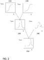
- Fig. 2 an illustration of how a spectral band may be observed by a combination of two filters is illustrated. It also is clear that the array of hundreds of filters may be envisioned as a similar concept to that in Fig. 2 repeated many times.
- a first QD filter 210 have an associated spectral transmission response as illustrated and indicated as Trans.
- a second QD filter 220 have a shifted associated spectral transmission associated with a different nature of the quantum-dots included in the filter, for example the QDs may have a larger diameter in the QD filter of 220.
- the difference curve of a flat irradiance of light of all wavelength (white light) result from the difference of the absorption result from light that traverses filter 220 and that traverses filter 210.
- the effect of irradiating through these two filters is that the difference curve would indicate spectral response in the band 230 depicted.
- the absorption filters based on QDs may include QDs that have quenching molecules on their surfaces. These molecules stop the QD from emitting light after it absorbs energy in appropriate frequency ranges. More generally, the QD filters may be formed from nanocrystals with radii smaller than the bulk exciton Bohr radius, which leads to quantum confinement of electronic charges. The size of the crystal is related to the constrained energy states of the nanocrystal and generally decreasing the crystal size has the effect of a stronger confinement. This stronger confinement affects the electronic states in the quantum-dot and results in an increased the effective bandgap, which results in shifting to the blue wavelengths both of both optical absorption and fluorescent emission.
- the controller 300 includes one or more processors 310, which include one or more processor components coupled to a communication device 320. In some embodiments, a controller 300 is used to transmit energy to the energy source placed in the device.
- the processors 310 be coupled to a communication device 320 configured to communicate energy via a communication channel.
- the communication device 320 is used to electronically communicate with components within the media insert, for example.
- the communication device 320 may also be used to communicate, for example, with one or more controller apparatus or programming/interface device components.
- the processor 310 is also in communication with a storage device 330.
- the storage device 330 comprise any appropriate information storage device, including combinations of magnetic storage devices, optical storage devices, and/or semiconductor memory devices such as Random Access Memory (RAM) devices and Read Only Memory (ROM) devices.
- RAM Random Access Memory
- ROM Read Only Memory
- the storage device 330 stores a program 340 for controlling the processor 310.
- the processor 310 performs instructions of a software program 340, and thereby operates in accordance with the present invention.
- the processor 310 receives information descriptive of media insert placement, active target zones of the device.
- the storage device 330 also stores other pre-determined biometric related data in one or more databases 350 and 360.
- the database include, for example, predetermined retinal zones exhibiting changes according to cardiac rhythm or an abnormal condition correlated with the retinal vascularization, standard measurement thresholds, metrology data, and specific control sequences for the system, flow of energy to and from a media insert, communication protocols, and the like.
- the database may also include parameters and controlling algorithms for the control of the biometric based monitoring system that reside in the device as well as data and/or feedback that can result from their action. In some embodiments, that data be ultimately communicated to/from an external reception wireless device.
- a single and/or multiple discrete electronic devices are included as discrete chips.
- energized electronic elements are included in a media insert in the form of stacked integrated components.
- a media insert may include numerous layers of different types which are encapsulated into contours consistent with the environment that they will occupy. In some embodiments, these media inserts with stacked integrated component layers assume the entire shape of the media insert. Alternatively in some cases, the media insert occupy just a portion of the volume within the entire shape.
- these thin film batteries 430 may be used to provide energization.
- these thin film batteries 430 comprise one or more of the layers that be stacked upon each other with multiple components in the layers and interconnections there between.
- the batteries 430 are depicted as thin film batteries for exemplary purposes, there may be numerous other energization elements consistent with the embodiments herein including operation in both stacked and non-stacked embodiments.
- cavity based laminate form batteries with multiple cavities may perform equivalently or similarly to the depicted thin film batteries.
- interconnections between two layers there be additional interconnections between two layers that are stacked upon each other.
- interconnection may be made through solder ball interconnections between the layers. In some embodiments only these connections are required; however, in other cases the solder balls contact other interconnection elements, as for example with a component having through layer vias.
- a layer 425 may be dedicated for the interconnections of two or more of the various components in the interconnect layers.
- the interconnect layer 425 contain, vias and routing lines that can pass signals from various components to others.
- interconnect layer 425 provide the various battery elements connections to a power management unit 420 that may be present in a technology layer 415.
- the power management unit 420 has circuitry dedicated to supplying voltage sources with controlled characteristics 440.
- Other components in the technology layer 415 include, for example, a transceiver 445, control components 450 and the like.
- the interconnect layer 425 may function to make connections between components in the technology layer 415 as well as components outside the technology layer 415; as may exist for example in the integrated passive device 455. There be numerous manners for routing of electrical signals that be supported by the presence of dedicated interconnect layers such as interconnect layer 425.
- the technology layer 415 is included as multiple layers as these features represent a diversity of technology options that may be included in media inserts.
- one of the layers includes CMOS, BiCMOS, Bipolar, or memory based technologies whereas the other layer includes a different technology.
- the two layers may represent different technology families within a same overall family; as for example one layer include electronic elements produced using a 0.5 micron CMOS technology and another layer include elements produced using a 20 nanometer CMOS technology. It is apparent that many other combinations of various electronic technology types would be consistent within the art described herein.
- the media insert include locations for electrical interconnections to components outside the insert. In other examples, however, the media insert also include an interconnection to external components in a wireless manner. In such cases, the use of antennas in an antenna layer 435 provides exemplary manners of wireless communication. In many cases, such an antenna layer 435 is located, for example, on the top or bottom of the stacked integrated component device within the media insert.
- the energization elements such as batteries 430 may be included as elements in at least one of the stacked layers themselves. It be noted as well that other embodiments are possible where the battery elements 430 are located externally to the stacked integrated component layers. Still further diversity in embodiments derive from the fact that a separate battery or other energization component may also exist within the media insert, or alternatively these separate energization components may also be located externally to the media insert. In these examples, the functionality be depicted for inclusion of stacked integrated components, it be clear that the functional elements may also be incorporated into biomedical devices in such a manner that does not involve stacked components and still be able to perform functions related to the embodiments herein.
- Components of the quantum-dot spectrometer system 410 may also be included in a stacked integrated component architecture.
- the quantum-dot spectrometer system 410 components are attached as a portion of a layer.
- the entire quantum-dot spectrometer system 410 also comprises a similarly shaped component as the other stacked integrated components.
- the components not be stacked but laid out in the peripheral regions of the ophthalmic device or other biomedical device, where the general functional interplay of the components function equivalently however the routing of signals and power through the entire circuit differ.
- Quantum-dot emitters may be fashioned in a manner similar to the formation of light emitting diodes. Layers of materials surround the quantum-dots to create light emitting diodes with the quantum-dots. Organic layers act as electron donors and as hole donors into the quantum-dot layer. In a non-limiting example, the QDs be sandwiched between electron transport layers and hole transport layers. Application of electric potential to electrodes connected to the electron transport layer and the hold transport layer excite the QD into photoluminescence at a wavelength band characteristic of the QDs.
- electron transport layers and hole transport layers include tris-(8-hydroxyquinoline) aluminum; bathocuproine; 4,4'-N,N'-dicarbazolylbiphenyl; poly(2-(6-cyano-6'-methylheptyloxy)- 1,4-phenylene); poly[(9,9-dihexylfluorenyl-2,7-diyl)-co-(1,4- ⁇ benzo-[2,1',3]thiadiazole ⁇ )]; poly[2-methoxy-5-(2-ethylhexyloxy)-1,4-phenylenevinylene]; 4,4-bis[N-(1-naphyl)-N-phenylamino] biphenyl; 2-(4-biphenylyl)-5-(4-tertbutylphenyl)-1,3,4 oxadiazole; poly ⁇ 3,4-ethylene dioxythiophene; poly(9,9'-dioctylfluorene
- the quantum-dot layer Once excited by a current (such as from the power management unit 420), the quantum-dot layer emit light at a designed specified wavelength from the quantum-dot spectrometer system 410.
- the emitted light interacts with an outside environment, or with a specific sample or samples in the environment, wherein the sample or samples absorb the emitted light at certain wavelengths.
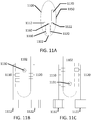
- the quantum-dot spectrometer then receive the remaining light, which has been transmitted through the sample or samples, in a quantum-dot detector (refer to Fig. 11A for one exemplary embodiment) within the quantum-dot spectrometer system 410.
- millimeter or nanometer sized quantum-dot detectors may be implemented into a quantum-dot spectrometer system 410 (see also, Fig. 11A , at 1120).
- Current quantum-dot detectors rely on charged-coupled devices (CCD); however, CCDs do not currently provide the size scale required for millimeter- or nanometer sized quantum-dot spectrometers. Rather, smaller photodiode arrays may be used to achieve the size requirements.
- Photodiodes are semiconductor devices that convert light into energy. Millimeter or nanometer sized photodiodes may be constructed through photolithographic means.
- a biomarker generally refers to a measurable indicator of some biological state or condition.
- the term is also occasionally used to refer to a substance the presence of which indicates the existence of a living organism.
- life forms are known to shed unique chemicals, including DNA, into the environment as evidence of their presence in a particular location.
- Biomarkers are often measured and evaluated to examine normal biological processes pathogenic processes, or pharmacologic responses to a therapeutic intervention. In their totality, these biomarkers reveal vast amounts of information important to the prevention and treatment of disease and the maintenance of health and wellness.
- Biomedical devices configured to analyze biomarkers be utilized to quickly and accurately reveal one's normal body functioning and assess whether that person is maintaining a healthy lifestyle or whether a change be required to avoid illness or disease.
- Biomedical devices may be configured to read and analyze proteins, bacteria, viruses, changes in temperature, changes in pH, metabolites, electrolytes, and other such analytes used in diagnostic medicine and analytical chemistry.
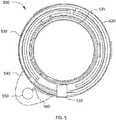
- an ophthalmic insert 500 including components that form an exemplary quantum-dot (QD) spectrometer system.
- the demonstrated ophthalmic insert is shown in an exemplary annular form having an internal border of 535 and an external border of 520.
- a broadband QD spectrometer system 550 which in certain exemplary embodiments be positioned on a flap 540.
- the flap 540 be connected to the insert 500 or be an integral, monolithic extension thereof. The flap 540 properly positions the broadband QD spectrometer system 550 when an ophthalmic device comprising a QD detector is worn.
- the flap 540 allows the broadband QD spectrometer system 550 to overlap with portions of the user's eye away from the optic zone.
- the broadband QD spectrometer system 550 is capable of determining an analyte, in terms of its presence or its concentration, in a fluid sample.
- an analyte sample be exposed to an excitation light source which be passed through an array of different QD filters.
- This light source with the array of filters is located within the body of the analytical system.
- the light source may comprise a solid-state device or devices similar to a light emitting diode (LED).
- the QD filtered light source be irradiated through a sample and reflect back on some tissue layers to a detector array
- An electronic control bus of interconnect features 560 provide the signals to the light source or sources and return signals from the detectors.
- the powered electronic component provides the signals and power aspects.
- the exemplary embodiment of Fig. 5 illustrates a battery power source 530 to the electronic circuitry 510.
- energization also is provided to the electronic circuitry by the coupling of energy through wireless manners such as radiofrequency transfer or photoelectric transfer.
- a Microfluidic System may be utilized to pull sample from an outside environment into the biomedical device in order to analyze the sample in a more controlled fashion within an internal region defined by the insert pieces.
- Fig. 6A a top view of an exemplary multi-piece annular shaped insert 600 is depicted.
- the exemplary multi-piece annular shaped insert 600 be a ring of material around a central optical zone that is devoid of material.
- the annular shaped insert 600 be defined by an exterior extent 620 and an internal annulus edge 630. Included in between the exterior extend 620 and the internal annulus edge 630 are found energization elements 640, interconnect features 645 of various types and/or an electronic circuit element 650.
- FIG. 6B a first amplified partial cross sectional representation 690 of the exemplary multipiece annular shaped form insert 600 of Fig. 6A is depicted.
- the cross section 690 reveals that the annular shaped insert 600 as a combination of a front insert piece 691 and a rear insert piece 692.
- the front insert piece 691 and the rear insert piece 692 be joined and sealed together.
- other structural features and means can be implemented to join both pieces together.
- Also shown in an encapsulated location is an integrated circuit element 693 connected to interconnection elements.
- FIG. 6C a second amplified partial cross sectional representation 695 of the exemplary multipiece annular shaped form insert 600 of Fig. 6A is depicted.
- a different type of structure may be found, as depicted in cross section 695.
- this ability to allow component(s) 698 situated within the annular shaped insert 600 to controllably interface with fluids and/or gasses in their exterior environment can, in some embodiments, enable for the incorporation of QD spectrometer elements within ophthalmic device.
- FIG. 7 a top view of a section of a Microfluidic Analytical System 700 is illustrated with an exemplary pumping mechanism 760 as well as sampling regions and controlling components is depicted.
- control circuitry 740 be electrically connected to components of the micro fluidic analytical system through interconnect(s) 720.
- a control element 750 for a pore (not shown) be included and be useful for connecting the Microfluidic Analytical System 700 to fluid (not shown) outside of the insert. Exemplary aspects of different designs of pores may be found in following sections; however, the pore allow fluid samples to be passed from outside the insert environment to a pumping element 760.
- the pumping element 760 have an activating or driving component 730 that be capable of engaging the pump element 760.
- the pump element 760 comprise a flexible and collapsible membrane that be activated by the application of pressure upon the membrane.
- a fluid may fill a cavity 731 and flow through a tube 735 connecting the cavity 731 to the pumping element 760.
- the cavity 731 includes features allowing the application of pressure upon the fluid contained within.
- piezoelectric components may be used to expand volume on the application of voltage thus pressurizing the contained fluid.
- thermo-compressive materials respond to a temperature change that be controlled by the application of electric energy to a heating element.
- an Electrowetting on Dielectric (EWOD) component exert a pressure on the fluid by a change in the wetting characteristics of a surface in cavity 731 upon the application of a potential.
- EWOD Electrowetting on Dielectric
- Still further diversity may derive from the use of EWOD components to influence the flow of fluids themselves rather than the use of mechanical pumping means.
- the pump element 760 forces fluid to flow through a channel 770 and subsequently into an analyzing chamber 705 of the Microfluidic Analytical System 700. Further detail of the components in such chambers 705 will be described in following sections, but briefly stated the fluid flow through the analyzing chamber 705 and cause influences to occur on electrode(s) 710 which may be part of the components.
- FIG. 8 a top view partial section of an exemplary Microfluidic Analytical System 800 with a fluid sample being flowed through the microfluidic analysis component is illustrated.
- the components may be observed to be deployed in a curvilinear fashion as there may be numerous details that change in a curvilinear system including, for example, the exact shapes of electrodes and chamber cross sections.
- linear analytical systems be formed that have dimensions that allow them to fit in the ocular environment.
- the entire substrate that the chamber rests upon can be curved allowing it to rest upon the roughly spherical surface of an eye.
- Micro fluidic Analytical System 800 The details of the three dimensional nature of the analysis chamber factor into models related to the performance of the systems. For illustration purposes, however, this description declares these nuances, but will illustrate an exemplary embodiment by curving the features of a linear Micro fluidic Analytical System 800. Depicted in the portion of the Micro fluidic Analytical System 800, a micro-channel 850 for receiving and transporting fluid samples is shown. These fluid samples may be pumped, for example, by the previously discussed pumping system (e.g. 760 in Fig. 7 ) from an external location. For example, fluid samples may be sampled from ocular fluid that surrounds a contact lens containing the Microfluidic Analytic System 800. An analyte sensor 870 is found for example along the micro-channel.
- This analyte sensor 870 is capable of performing one or more of: an electrochemical analysis step, a photometric analysis step or other analytical steps upon fluid samples. In some examples QD spectrometry is performed in these regions.
- the analysis step relate to a photometric sensing of glucose concentration based on a fluorescence sensor typology using one or more components.
- the sensor detects the presence of reaction products from a glucose oxidase interaction with portions of the analyte sensor 870 and the fluid sample. There may be numerous electrical interconnections 820 which connect the sensing element 870 to control electronics.
- the fluid flows into the micro-channel 850 it displace other fluid in a particular region, or on an initial use displace ambient gas in the channel.
- a fluid flows, it is sensed by a pre-sensor micro-channel portion comprising electrodes 860 and 861 as well as a post-sensor portion comprising electrodes 862 and 863.
- the measurement of impedance between electrodes such as 860 and 861 is used to sense the flow of material.
- the resistance of a chain of electrodes 862 and 863 is altered by the presence of a fluid within the micro-channel 850, or the presence of a front between two fluids of different characteristics residing in the micro-channel 850.
- a fluid 880 flows through the micro-channel from an empty region of the micro-channel 890 to be sampled.
- micro-channel portion at 890 represent a different solution of fluid that for example have different concentration of electrolytes, and therefore, conductivity than that of typical tear fluid.
- measuring impedances, or ohmic resistances, between position electrodes 860-863 in embodiments of the present invention may be accomplished by applying a voltage therebetween and measuring the resulting current. Either a constant voltage or an alternating voltage be applied between the position electrodes 860-863 and the resulting direct current (DC) or alternating current (AC), respectively, measured. The resulting DC or AC current is then used to calculate the impedance or ohmic resistance.
- measuring impedance may involve measuring both an ohmic drop (i.e., resistance [R] in Ohms or voltage/current) and measuring capacitance (i.e., capacitance in Farads or coulombs/volt).
- impedance may be measured, for example, by applying an alternating current to the position electrode(s) 860-863 and measuring the resulting current.
- alternating current either resistive or capacitive effects prevail in determining the measured impedance.
- the pure resistive component can prevail at lower frequencies while the pure capacitive component can prevail at higher frequencies.
- the phase difference between the applied alternating current and the measured resulting current can be determined. If there is zero phase shift, the pure resistive component is prevailing. If the phase shift indicates that the current lags the voltage, then the capacitive component is significant. Therefore, depending on the frequency of an applied alternating current and position electrode configuration, it can be beneficial to measure either resistance or a combination of resistance and capacitance.
- impedance measurements be performed by, for example, applying an alternating voltage between first position electrode 830 and a final position electrode connection 810 and measuring the resulting alternating current.
- the chain of electrodes including 860, 861, 862 and 863 can be a portion of a capacitor, (along with any substance [e.g., air or a liquid sample] within micro-channel 850 between subsequent position electrodes and any layers that be separating the position electrodes from direct contact with the fluid in the micro-channel 850), the measured current be used to calculate the impedance.
- the presence or absence of a liquid sample in micro-channel 850, 890 between electrodes will affect the measured current and impedance.
- the frequency and amplitude of the alternating voltage applied between a first and second position electrodes 860-863 can be predetermined such that the presence of a liquid sample between a first and second position electrodes 860-863 is detected by a significant increase in measured current.
- the magnitude of the applied voltage can be, for example, in range from about 10m V to about 2 volts for the circumstance of an ophthalmic tear fluid sample and carbon based or silver-based ink position electrodes.
- the lower and upper limits of the applied voltage range are dependent on the onset of electrolysis or electrochemical decomposition of the liquid sample.
- the alternating voltage can be applied, for example, at a frequency that results in a negligible net change in the liquid sample's properties due to one or more electrochemical reaction.
- Such a frequency range can be, for example, from about 10 Hz to about 100 kHz with a voltage waveform symmetrical around 0 Volts (i.e., the RMS value of the alternating voltage is approximately zero).
- analyte sensor 870 and position electrodes 860-863 can each be in operative communication with the micro-channel 850.
- position electrodes 860-863 employed in embodiments of the present invention can be formed of any suitable conductive material known to those skilled in the art, including conductive materials conventionally used as analytical electrode materials and, in particular, conductive materials known as suitable for use in flexible circuits, photolithographic manufacturing techniques, screen printing techniques and flexo-printing techniques.
- Suitable conductive materials include, for example, carbon, noble metals (e.g., gold, platinum and palladium), noble metal alloys, conductive potential-forming metal oxides and metal salts.
- Position electrodes can be formed, for example, from conductive silver ink, such as the commercially available conductive silver ink Electrodag 418 SS.
- a top view section of an exemplary Microfluidic Analytical System component 900 with a waste or fluid retention vessel 930 is depicted.
- electrode 910 for measuring the flow rate of fluid in the system is an end electrode of many others (not depicted in Fig. 9 ). Fluid flow through the microchannel 920 and continue to a fluid retention vessel 930.
- the fluid retention vessel is used, for example, for higher volume of fluid analysis therein.
- a pore 940 include a pore control element 945 for connecting the fluid retention vessel 930, which be also be used as a waste storage element, 930 to regions located external to the insert.
- the pore control element 945 connection be useful for equalizing gas pressure as the microfluidic components fill with fluid.
- the pore 940 and pore control element 945 be useful for emitting fluid from the ophthalmic device.
- the pore 940 also is useful for connecting an end of the Micro fluidic Analytical System to its external region in an eye environment, which can allow for continuous monitoring without the removal of the ophthalmic device.
- the pore 940 and pore control element 945 be useful for flow control through the Micro fluidic Analytical System in a storage location, such as the fluid retention vessel 930.
- the Microfluidic Analytical System may be cleansed or refreshed by the flowing of solutions through the system and, in some embodiments, subjected to calibration protocols. Control of these functions is performed by the integrated circuit components within the lens which also is in communication with external controlling systems.
- FIG. 10 a top view section of an exemplary pumping mechanism 1000 for a Micro fluidic Analytical System using lab on a chip component 1010 is depicted.
- a lab on a chip component 1010 share many aspects with the embodiment of the Microfluidic Analytical System that has been previously discussed. Similarly, however, in some embodiments small droplets be moved around within the lab on a chip 1010 not through the action of a pump 1060 but by control of the droplets with EWOD components. Droplets are combined in elements of the lab on a chip component 1010 to perform chemical processing. Numerous analysis techniques may be performed, for example, in some embodiments the analysis of glucose as an analyte is performed.
- the technique for this analysis include, for example, an electrochemical or photometric technique as described or other techniques that relate to the mixing of chemical substances that be initially stored in the lab on a chip component 1010.
- Quantum-dot based spectroscopy techniques are performed in or through the lab on a chip component.
- QD based dyes be located in a droplet that is mixed with a sample obtained from the environment of the biomedical device. The resulting interaction with a targeted analyte yields spectroscopic signals that be used to calculate a concentration of the analyte for example.
- an electronic circuit 1020 capable of controlling various components including a lab on a chip component 1010 is implemented.
- a pore 1050 and a pore control system 1055 control the sampling of fluid samples from the ophthalmic device environment.
- a pump actuator 1030 actuates a pump 1060 which may be mechanical in nature such as a membrane based pump. Droplets of a fluid sample are pumped into micro-channel 1015 for metering of the volume and sample flow rate through the use of electrodes such as electrode 1016 as described in the present disclosure.
- the droplets are provided to the lab on a chip component 1010 through a channel 1011 where it is further processed.
- the lab on a chip component 1010 may use the pumped action on the sample to control flow within itself, or in other embodiments, it control the flow rate of the sample provided to it on its own.
- the lab on a chip component 1010 is able to sense fluid in its environment without the need of an external pumping system. However, a pore 1050 still is useful to provide control over flow of external fluid into the environment of the lab on a chip component. Thereafter the lab on a chip component 1010 may sample the introduced sample on its own, for example, by the control through electrowetting on dielectric or electrophoresis features that can attract and move fluid samples.
- the lab on a chip component 1010 may comprise a design that be consistent with the present description including, for example, very thin lab on chip flexible components to allow for the deformation into a shape consistent with the three dimensional shape of an ocular surface.
- the shape and thickness of the lab on a chip component 1010 allow it to be included in a planar form within the ophthalmic insert device.
- Fig. 11A illustrates an exemplary QD Spectrometer system in a biomedical device 1100.
- the illustration in Fig. 11A may utilize a microfluidic system as illustrated in Fig. 10 , or alternatively, may utilize a more passive approach to collecting samples wherein a sample fluid passively enters a channel 1102.
- the channel 1102 is internal to the biomedical device in some examples and in other examples, as illustrated; the biomedical device surrounds an external region with a reentrant cavity.
- the biomedical device creates a channel of fluid external to itself, the device also contain a pore 1160 to emit reagents or dyes to interact with the external fluid in the channel region.
- the passive sampling may be understood with reference to an example where the biomedical device is a swallowable pill.
- the pill contains regions that emit medicament 1150 as well as regions that analyze surrounding fluid such as gastric fluid for the presence of an analyte, where the analyte be the medicament for example.
- the pill contains controller 1170 regions proximate to the medicament where control of the release of the medicament is made by portions of the biomedical pill device.
- An analysis region comprises a reentrant channel within the biomedical pill device that allows external fluid to passively flow in and out of the channel. When an analyte, for example in gastric fluid, diffuses or flows into the channel it becomes located between the analysis region as depicted in Fig. 11A .
- a sample 1130 pass in the emission portion of a Quantum-dot (QD) emitter 1110.
- the QD emitters 1110 receive information from a QD emitter controller 1112 instructing the QD emitters 1110 to emit an output spectrum of light across the channel 1102.
- the QD emitter acts based on emission properties of the quantum-dots. In other examples, the QD emitter act based on the absorption properties of the quantum-dots. In the examples utilizing the emission properties of the quantum-dots, these emissions be photostimulated or electrically stimulated. In some examples of photostimulation; energetic light in the violet to ultraviolet be emitted by a light source and absorbed in the quantum-dots. The excitation in the QD relaxes by emitting photons of characteristic energies in a narrow band. As mentioned previously, the QDs are engineered for the emission to occur at selected frequencies of interest.
- QDs be formed into the layered sandwiched mentioned previously between electrically active layers that donate electrons and holes into the QDs. These excitations similarly emit characteristic photons of selected frequency.
- the QD emitter 1110 may be formed by inclusion of nanoscopic crystals, that function as the quantum-dots, where the crystals be controlled in their growth and material that are used to form them before they are included upon the emitter element.
- a spectrum of light frequencies is emitted by QD emitter 1110 and pass thru the sample 1130.
- the sample 1130 absorbs light from some of the emitted frequencies if a chemical constituent within the sample is capable of absorbing these frequencies. The remaining frequencies that are not absorbed continue on to the detector element, where QD receivers 1120 absorb the photons and convert them to electrical signals. These electrical signals are converted to digital information by a QD detector sensor 1122.
- the sensor 1122 is connected to each of the QD receivers 1120, or in other examples the electrical signals be routed to centralized electrical circuits for the sensing.
- the digital data is used in analyzing the sample 1130 based on pre-determined values for QD wavelength absorbance values.
- the QD system is depicted in a manner where the sample is passed in front of spectral analysis elements that are spatially located. This may be accomplished for example in the manners described for the microfluidic progression.
- the sample 1130 contain analytes that diffuse inside an region of a biomedical device that encloses external fluid with material of the biomedical device to form a pore or cavity into which the sample passively flow or diffuse to an analytical region that passes light from emitters within the biomedical device, outside the biomedical device, and again to detectors within the biomedical device.
- Figs. 11B and 11C depict such movement as the difference between the locations of the sample 1130 which has moved along the analysis region to the new location 1131.
- the QDs are consolidated to act in a single multidot location where the excitation means and the sensing means are consolidated into single elements for each function.
- Some biomedical devices such as ophthalmic devices may have space limitations for a spectrometer comprising more than a hundred quantum-dot devices, but other biomedical devices may have hundreds of quantum-dot devices which allow for a full spectrographic characterization of analyte containing mixtures.
- the QD analytical system may also function with microfluidic devices to react samples containing analytes with reagents containing dyes.
- the dye molecules react with specific analytes.
- an example of such a binding is the FRET indicators.
- the dye molecules have absorption bands in the ultraviolet and visible spectrum that are significantly strong, which also be referred to as having high extinction coefficients. Therefore, small amounts of a particular analyte be selectively bound to molecules that absorb significantly at a spectral frequency, which be focused on by the QD analytical system.
- the enhanced signal of the dye complex allow for more precise quantification of analyte concentration.
- a microfluidic processing system mixes an analyte sample with a reagent comprising a dye that will bind to a target analyte.
- the microfluidic processing system mixes the two samples together for a period that would ensure sufficient complexing between the dye and the analyte. Thereafter, in some examples, the microfluidic processing system moves the mixed liquid sample to a location containing a surface that binds to any uncomplexed dye molecules. When the microfluidic system then further moves the sample mixture into an analysis region, the remaining dye molecules will be correlatable to the concentration of the analyte in the sample.
- the mixture may be moved in front of either quantum-dot emission light sources or quantum-dot absorption filters in the manners described.
- a type of fluorescent dye may be formed by complexing quantum-dots with quenching molecules.
- a reagent mixture of quantum-dots with complexed quenching molecules is introduced into a sample containing analytes, for example in a microfluidic cell, within a biomedical device.
- the quenching molecules contain regions that bind to analytes selectively and in so doing separate the quenching molecule from the quantum-dot.
- the uncomplexed quantum-dot may now fluoresce in the presence of excitation radiation.
- combinations of quantum-dot filters are used to create an ability to detect the presence of enhanced emission at wavelengths characteristic of the uncomplexed quantum-dot.
- a solution of complexed quantum-dots be stored within a microfluidic processing cell of a biomedical device and be used to detect the presence of analytes from a user in samples that are introduced into the biomedical device.
- a quantum-dot 1210 comprise an exemplary material such as indium phosphide / zinc sulfide, copper indium sulfide / zinc sulfide, cadmium selenide, cadmium sulfide, lead sulfide, lead selenide, indium arsenide, and indium phosphide as examples.
- Other examples comprise nanoparticles of silicon and carbon. Any material that may form a strained band structure of the type characteristic of a quantum-dot may be used in some examples.
- the quantum-dot core may be surrounded by a core shell coating that provides interface from the quantum-dot to its outside environment.
- a biocompatible lipid coating which allow for the binding of quenching molecules to the surface of the dot also be provided.
- the quenching molecules 1211 are bound to the quantum-dot surface and act to facilitate electronic energy transfer from the quantum-dot which results in a de-excitation of the quantum-dot energy without fluorescent emission.
- a solution of the quantum-dots is mixed 1220 with a sample containing analytes 1221. During the mixing, analytes complex 1230 with the quenching molecules forming an analyte/quenching molecule complex 1231.
- the complexing of the analyte with the quenching molecule decouple 1240 the quenching molecule from the quantum-dot, resulting in a free analyte/quenching molecule 1241 and an uncomplexed quantum-dot.
- the quantum-dot be excited by photons at energy distinct from the inherent fluorescent energy of the quantum-dot and the unquenched quantum-dot will now fluoresce.
- the concentration of the analyte in the sample is a function of the fluorescence signal emanating from the unquenched quantum-dot.
- the microfluidic analysis system includes a light source, which be a quantum-dot light emitting diode for example or other light sources with energy distinct from the fluorescence signal.
- a detector is configured to detect all light that traverses a spectral analysis region.
- quantum-dot absorbance filters or other light filters may be used to selectively pass the energy band of the quantum-dot fluorescence signal.
- a user obtains a biomedical device comprising: a quantum-dot device or reagent, and a sample transport mean.
- the biomedical device is capable of obtaining a fluid sample from the user and passing it into the path of light emanating from a quantum-dot emission device or other light source.
- the light source include a quantum-dot light emitting diode or a set of quenched quantum-dot filters configured to isolate selected spectral regions for analysis. Other light sources such as light emitting diodes and lasers may also be used.
- the biomedical device is obtained by an intermediary for the purposes of use by an end user.
- the biomedical device is located in contact with a user's biological fluid.
- the location may include regions proximate to fluid emanations from a user such as, in non-limiting examples, tear fluid, blood, saliva, and waste products. Or, the location may include subcutaneous locations and locations within or in contact with the user's body cavity and venous system.
- the biomedical device is used to sample the user's biological fluid.
- the biomedical device engages a calibration protocol either in an autonomous fashion or under direction of an external device or communication signal.
- an aliquot of the sample of user's biological fluid be mixed with a reagent comprising a dye compound.
- the mixing occurs by passive diffusion based interaction, or alternatively, be actively controlled such as with a microfluidic processing system as has been described herein.
- the dye compound is an organic dye or, in some examples, a quantum-dot based dye.
- the dye changes a spectral characteristic, such as fluorescence emission or spectral absorbance, when it binds with an analyte in the sample.
- the mixture subsequently is processed to remove unreacted dye, particularly in examples where the binding of the dye to the analyte does not change a spectral characteristic of the dye.
- the sample is mixed with a reagent that renders unbound dye inert or alternatively the sample be passed in contact with a surface that bind and immobilize or separate out unbound dye.
- the sample mixture is moved from a reaction region to an analysis region in some examples. In other examples, the same location where reactions occur be used to perform a spectral analysis.
- the sample is irradiated with a light source.
- the light source may be from numerous example types including sources comprising quantum-dots as have been described.
- the irradiation proceed through the sample and light that emerges from the sample be detected in a spectral region by a detector system in the biomedical device.
- the detected emanation signal be converted into an electrical signal and also be converted into a digital data value that also be conveyed as an electrical signal stream.
- the biomedical device include on board processing devices and software algorithms that allow for a calculation of an estimate of a concentration of the analyte in the sample.
- the raw data signals, detector (calibration) signal without analyte, and detector signal with analyte be transmitted without further signal processing in the biomedical device.
- the raw data signals are communicated, for example, via wireless communication, to an external transceiver.
- a calculated estimate of the concentration of an analyte also is communicated.
- sensor data that are transmitted in addition to the analysis system data, which may include in a non-limiting perspective sensor measurements of the temperature sensed in a region of the biomedical device.
- the QD spectrometer systems may be utilized in several different biomedical devices including: ophthalmic devices, biomedical pills, hygiene products, patches, and other similar biomedical products that are on or in proximity to the body in such a manner to detect and analyze analytes.
- the information obtained from the QD spectrometer system may be utilized for biometric analysis such as real-time readings of glucose for diabetics, as a non-limiting example.
- the information obtained may be communicated to a tertiary device, such as a smart phone, as disclosed in relationship to Fig. 4 .
- thresholds values are programmed into a software program.
- threshold values include, for example, acceptable levels for the concentration of glucose biomarkers in ocular fluid.
- the use of other biomarkers used to monitor different conditions such as depression, high blood pressure, and the like, are also within the inventive scope of aspects of the present disclosure.
- the preprogrammed levels may be different depending on whether the ocular fluid sample target is, for example, tear fluid or an interstitial fluid.
- the program is stored and executed using one or both a processor forming part of the Media Insert of the ophthalmic device and an exterior device in communication with the processor of the Media Insert.
- An exterior device includes a smart phone device, a PC, a specialized biomedical device user interface, and the like; and be configured to include executable code useful to monitor properties of ocular fluid samples.
- Ocular fluid properties may be measured by one or more sensors contained in the ophthalmic device. Sensors may include electrochemical sensors and/or photometric sensors.
- the sensor analysis step relate to a photometric sensing of glucose concentration based on a QD spectrometry.
- the sensor detects the presence of reaction products from a glucose oxidase interaction with portions of the analyte sensor and the fluid sample.
- the ophthalmic device including a microfluidic system be placed in contact with a portion of the anterior ocular surface of the eye and worn by a user.
- the ophthalmic device is in a form of an energized contact lens and the step be achieved when the contact lens is placed on the eye surface.
- the biomedical device be, for example, in the form of an intraocular lens, punctalplug, biomedical pill, or any other similar biomedical device, and still include aspects of the QD spectrometer system described in the present disclosure.
- the ophthalmic device is described throughout the specification in singular form, it will be understood by one skilled in the art that two ophthalmic devices (e.g. contact lenses), one placed on each eye, may function together to provide functionality aspects of the present disclosure.
- concentration changes of biomarkers be monitored using the one or more sensors.
- the monitoring of the biomarkers occurs at a predetermined frequency/bandwidth or upon demand through a user interface and/or an activation sensor in the ophthalmic device.
- Biomarkers can include those correlated to glucose levels, depression, blood pressure and the like.
- the processor of the ophthalmic device can record the measured property/condition from a sample of ocular fluid. In some embodiments, the processor of the ophthalmic device stores it and/or sends it to one or more device(s) in communication with the ophthalmic device.
- the value recorded can be stored and analyzed in the user interface in communication with the ophthalmic lens, and/or, at step 1425, the analysis and recording can take place in the ophthalmic device.
- one or both the ophthalmic device and the user interface alert the user, and/or a practitioner, of the measured concentration.
- the alert is programmed to occur when the levels measured are outside the predetermined threshold values programmed, received and/or calculated by the ophthalmic device.
- the data and alerts are analyzed to perform one or more steps of: a) change measurement frequency according to the time of the day, b) identify personal patters in the changes of concentration levels measures, and c) change the measurement frequency according to the changes in concentrations measured.
- the time of the day change the frequency of measurements. For example, if the ophthalmic device is one that would remain in the eye during sleep, the number of measurements during 10 pm and 6am can decrease or stop.
- the frequency increase to detect changes due to the food consumption of the user.
- patterns in changes of the concentration levels are identified by the system. Using the identified patterns, the system alert the user of causes and/or, at step 1445, change the frequency according to the identified changes so that the system is more alert during critical identified conditions.
- Critical conditions can include events that would trigger a significant increase or decrease in glucose levels. Events can include, for example, holiday dates, exercise, location, time of the day, consumption of medicaments and the like.
- the originally programmed values are customized, periodically or in real time, according to identified patterns/conditions. This ability allows the system to increase its effectiveness by eliminating false alarms and increasing sensitivity at a critical condition. Effectiveness can promote user participation with the system thereby maximizing the benefits of the ophthalmic device and thereby providing a safe monitoring system.
- data relating to the user including, for example, the identified patterns, measurements, and/or preferences may become part of the medical history of the user. Medical history is stored securely by encrypting the data and/or restricting its access.
- an ophthalmic device including a QD spectrometer analytical system is placed in contact with ocular fluid.
- the ophthalmic device is in a form of an energized contact lens and the step be achieved when the contact lens is placed on the eye surface.
- the ophthalmic device is, for example, in the form of an intraocular lens or a punctal plug, and still includes aspects of the QD spectrometer system described in the present disclosure.
- changes in biomarkers in the ocular fluid can be monitored.
- Methods of monitoring the biomarker changes include, for example, steps illustrated in Fig. 14 .
- measured changes can be communicated in real time to a medicament-dispensing device in direct or indirect communication with the ophthalmic device.
- the changes in concentration of the monitored biomarkers in ocular fluid may include a time delay in relation to the concentration changes in the bloodstream of the user, upon detection, at step 1515 the medicament-dispensing device administer a medicament capable of lowering or raising concentrations to a normal level. For example, glucose levels be monitored and treated when they are outside a normal level.
- Continuous monitoring prevent uncontrolled blood sugar levels which may damage the vessels that supply blood to important organs, like the heart, kidneys, eyes, and nerves. Because an individual whose glucose levels reach a level that exposes him/her to the risks may feel fine, aspects of the present disclosure help take action upon early detection of the condition. Early detection not only bring back levels to a normal condition and/or make the user aware, but additionally prevent the more dramatic and permanent consequences including, for example, a heart attack or stroke, kidney failure, and blindness which have been known to occur when abnormal glucose levels are left untreated.
- the medicament administering device sends an alert to the user through its interface or using component of the ophthalmic device.
- the Media Insert include a light projection system, such as one or more LEDs, capable of sending a signal to the user.
- any further drug administering can be suspended to prevent overdosing of the system due to the time delay of the effect of the drug and the effect to be reflected in the tear fluid.
- the medicament requires 10-30 minutes to counteract the abnormal level, and upon its effect, take another 20 minutes to equalize concentrations in tear fluid. Consequently, programmed algorithms capable of correlating the condition, time delay, and appropriate subsequent dosing of medicaments can be programmed in the system to function safely.
- data relating to one or both the measured conditions and the medicament administration to the user may be stored and used as part of a treatment and/or medical history of the user.
Landscapes
- Health & Medical Sciences (AREA)
- Life Sciences & Earth Sciences (AREA)
- Physics & Mathematics (AREA)
- Engineering & Computer Science (AREA)
- General Health & Medical Sciences (AREA)
- Biomedical Technology (AREA)
- Molecular Biology (AREA)
- Pathology (AREA)
- Public Health (AREA)
- Heart & Thoracic Surgery (AREA)
- Veterinary Medicine (AREA)
- Animal Behavior & Ethology (AREA)
- Surgery (AREA)
- Medical Informatics (AREA)
- Biophysics (AREA)
- Ophthalmology & Optometry (AREA)
- Optics & Photonics (AREA)
- Chemical & Material Sciences (AREA)
- General Physics & Mathematics (AREA)
- Immunology (AREA)
- Biochemistry (AREA)
- Analytical Chemistry (AREA)
- Spectroscopy & Molecular Physics (AREA)
- Nuclear Medicine, Radiotherapy & Molecular Imaging (AREA)
- Signal Processing (AREA)
- Urology & Nephrology (AREA)
- Hematology (AREA)
- Medicinal Chemistry (AREA)
- Emergency Medicine (AREA)
- Artificial Intelligence (AREA)
- Psychiatry (AREA)
- Physiology (AREA)
- Power Engineering (AREA)
- Computer Vision & Pattern Recognition (AREA)
- Microbiology (AREA)
- Food Science & Technology (AREA)
- Crystallography & Structural Chemistry (AREA)
- Materials Engineering (AREA)
- Nanotechnology (AREA)
- Biotechnology (AREA)
Applications Claiming Priority (1)
| Application Number | Priority Date | Filing Date | Title |
|---|---|---|---|
| US14/863,933 US20170086676A1 (en) | 2015-09-24 | 2015-09-24 | Quantum-dot spectrometers for use in biomedical devices and methods of use |
Publications (2)
| Publication Number | Publication Date |
|---|---|
| EP3146898A1 EP3146898A1 (en) | 2017-03-29 |
| EP3146898B1 true EP3146898B1 (en) | 2018-11-14 |
Family
ID=56997367
Family Applications (1)
| Application Number | Title | Priority Date | Filing Date |
|---|---|---|---|
| EP16190406.5A Not-in-force EP3146898B1 (en) | 2015-09-24 | 2016-09-23 | Quantum-dot spectrometers for use in biomedical devices and methods of use |
Country Status (12)
| Country | Link |
|---|---|
| US (2) | US20170086676A1 (ko) |
| EP (1) | EP3146898B1 (ko) |
| JP (1) | JP2017060767A (ko) |
| KR (1) | KR20170036613A (ko) |
| CN (1) | CN107037017A (ko) |
| AU (1) | AU2016216628A1 (ko) |
| BR (1) | BR102016021549A2 (ko) |
| CA (1) | CA2941889A1 (ko) |
| IL (1) | IL247272A0 (ko) |
| RU (1) | RU2665202C2 (ko) |
| SG (1) | SG10201606961TA (ko) |
| TW (1) | TW201726059A (ko) |
Cited By (25)
| Publication number | Priority date | Publication date | Assignee | Title |
|---|---|---|---|---|
| US11510597B2 (en) | 2020-09-09 | 2022-11-29 | Know Labs, Inc. | Non-invasive analyte sensor and automated response system |
| US11529077B1 (en) | 2022-05-05 | 2022-12-20 | Know Labs, Inc. | High performance glucose sensor |
| US11689274B2 (en) | 2020-09-09 | 2023-06-27 | Know Labs, Inc. | Systems for determining variability in a state of a medium |
| US11696698B1 (en) | 2022-10-03 | 2023-07-11 | Know Labs, Inc. | Analyte sensors with position adjustable transmit and/or receive components |
| US11764488B2 (en) | 2020-09-09 | 2023-09-19 | Know Labs, Inc. | Methods for determining variability of a state of a medium |
| US11802843B1 (en) | 2022-07-15 | 2023-10-31 | Know Labs, Inc. | Systems and methods for analyte sensing with reduced signal inaccuracy |
| US11832926B2 (en) | 2020-02-20 | 2023-12-05 | Know Labs, Inc. | Non-invasive detection of an analyte and notification of results |
| US11903701B1 (en) | 2023-03-22 | 2024-02-20 | Know Labs, Inc. | Enhanced SPO2 measuring device |
| US11903689B2 (en) | 2019-12-20 | 2024-02-20 | Know Labs, Inc. | Non-invasive analyte sensor device |
| US12007338B2 (en) | 2020-09-09 | 2024-06-11 | Know Labs Inc. | In vitro sensor for analyzing in vitro flowing fluids |
| US12019034B2 (en) | 2020-09-09 | 2024-06-25 | Know Labs, Inc. | In vitro sensing methods for analyzing in vitro flowing fluids |
| US12023151B2 (en) | 2020-02-20 | 2024-07-02 | Know Labs, Inc. | Non-invasive analyte sensing and notification system with decoupled transmit and receive antennas |
| US12033451B2 (en) | 2022-08-15 | 2024-07-09 | Know Labs, Inc. | Systems and methods for analyte-based access controls |
| US12059239B2 (en) | 2018-05-08 | 2024-08-13 | Know Labs, Inc. | Electromagnetic shielding in non-invasive analyte sensors |
| US12092589B1 (en) | 2020-04-03 | 2024-09-17 | Know Labs, Inc. | In vitro analyte sensor using one or more detector arrays that operate in radio/microwave frequency bands |
| US12089927B2 (en) | 2020-02-20 | 2024-09-17 | Know Labs, Inc. | Non-invasive analyte sensing and notification system with decoupled and inefficient transmit and receive antennas |
| US12146841B2 (en) | 2021-11-10 | 2024-11-19 | Know Labs, Inc. | Non-invasive analyte sensor with temperature compensation |
| US12170145B2 (en) | 2023-03-22 | 2024-12-17 | Know Labs, Inc. | System and method for software and hardware activation based on real-time health parameters |
| US12193810B2 (en) | 2023-03-21 | 2025-01-14 | Know Labs, Inc. | System and method for performing surgery with real-time health parameter monitoring |
| US12201418B2 (en) | 2021-02-05 | 2025-01-21 | Know Labs, Inc. | Fixed operation time frequency sweeps for an analyte sensor |
| US12259281B2 (en) | 2021-11-10 | 2025-03-25 | Know Labs, Inc. | Non-invasive analyte sensor with superheterodyne circuit |
| US12318182B2 (en) | 2022-10-03 | 2025-06-03 | Know Labs, Inc. | Analyte sensors with antenna array |
| US12318203B2 (en) | 2022-08-15 | 2025-06-03 | Know Labs, Inc. | Vehicle interface systems and methods for analyte-based access control |
| USD1099332S1 (en) | 2023-06-06 | 2025-10-21 | Know Labs, Inc. | Non-invasive analyte sensor |
| US12603427B2 (en) | 2022-01-26 | 2026-04-14 | Know Labs, Inc. | Shape changing antenna and method for use thereof |
Families Citing this family (9)
| Publication number | Priority date | Publication date | Assignee | Title |
|---|---|---|---|---|
| ES2836849T3 (es) * | 2014-11-21 | 2021-06-28 | Nokia Technologies Oy | Un aparato, procedimiento y programa de ordenador para identificar rasgos biométricos |
| WO2018187693A1 (en) | 2017-04-06 | 2018-10-11 | TearDX LLC | Ocular devices and methods for the employment thereof |
| TWI707106B (zh) * | 2017-09-13 | 2020-10-11 | 晶元光電股份有限公司 | 發光裝置 |
| CN110823845B (zh) * | 2018-08-08 | 2021-05-25 | 京东方科技集团股份有限公司 | 光谱仪及其制作方法 |
| TWI743491B (zh) * | 2019-06-12 | 2021-10-21 | 國立陽明交通大學 | 可撓式生理感測裝置 |
| WO2021055645A1 (en) * | 2019-09-17 | 2021-03-25 | Quantum Materials Corp. | Using quantum dots for identification, authentication, and tracking of objects |
| CN115993342A (zh) | 2021-10-15 | 2023-04-21 | 谱钜科技股份有限公司 | 药物扫描与辨识系统及其使用方法 |
| TWI809530B (zh) * | 2021-10-15 | 2023-07-21 | 譜鉅科技股份有限公司 | 藥物掃描與辨識系統及其使用方法 |
| TWI887911B (zh) * | 2023-12-15 | 2025-06-21 | 台亞半導體股份有限公司 | 生物感測裝置 |
Family Cites Families (19)
| Publication number | Priority date | Publication date | Assignee | Title |
|---|---|---|---|---|
| US6544193B2 (en) * | 1996-09-04 | 2003-04-08 | Marcio Marc Abreu | Noninvasive measurement of chemical substances |
| US20020092558A1 (en) * | 2001-01-18 | 2002-07-18 | Kim Seong Bae | Integrated thin film cell and fabrication method thereof |
| JP2006512109A (ja) * | 2002-08-01 | 2006-04-13 | ザ ジョンズ ホプキンズ ユニバーシティ | 蛍光発光を用いた、分子構造の特定技術、および身体内腔の内側に並ぶ細胞種の治療技術 |
| US7092101B2 (en) * | 2003-04-16 | 2006-08-15 | Duke University | Methods and systems for static multimode multiplex spectroscopy |
| JP4663273B2 (ja) * | 2003-08-08 | 2011-04-06 | オリンパス株式会社 | カプセル型光センサー及びそれを用いた診断装置 |
| US7923801B2 (en) * | 2007-04-18 | 2011-04-12 | Invisage Technologies, Inc. | Materials, systems and methods for optoelectronic devices |
| JP2007209788A (ja) * | 2007-05-08 | 2007-08-23 | Olympus Corp | カプセル型医療装置 |
| US8608310B2 (en) * | 2007-11-07 | 2013-12-17 | University Of Washington Through Its Center For Commercialization | Wireless powered contact lens with biosensor |
| US8256286B2 (en) * | 2009-04-24 | 2012-09-04 | Sober Steering Sensors, Llc | System and method for detecting and measuring ethyl alcohol in the blood of a motorized vehicle driver transdermally and non-invasively in the presence of interferents |
| CN101788479A (zh) * | 2010-01-22 | 2010-07-28 | 华中科技大学 | 对基于量子点的荧光共振能量转移进行高灵敏度检测的方法 |
| KR20120055009A (ko) * | 2010-11-22 | 2012-05-31 | 한국전자통신연구원 | 다중 검출용 바이오 센서 |
| KR20130143102A (ko) * | 2011-01-03 | 2013-12-30 | 푼다시오 인스티튜트 데 레세르카 데 레네르기아 데 카탈루냐 | 주변광 스펙트럼을 얻고 발광을 수정하기 위한 광전자 디바이스,시스템 및 방법 |
| US8950862B2 (en) * | 2011-02-28 | 2015-02-10 | Johnson & Johnson Vision Care, Inc. | Methods and apparatus for an ophthalmic lens with functional insert layers |
| US9632102B2 (en) * | 2011-09-25 | 2017-04-25 | Theranos, Inc. | Systems and methods for multi-purpose analysis |
| US20130210652A1 (en) * | 2011-11-01 | 2013-08-15 | Nanoaxis, Llc | Nanotechnology enabled point of care testing device |
| JP6312605B2 (ja) * | 2012-01-26 | 2018-04-18 | ジョンソン・アンド・ジョンソン・ビジョン・ケア・インコーポレイテッドJohnson & Johnson Vision Care, Inc. | 眼科用装置向け積層型統合コンポーネント媒体挿入物 |
| EP2817613A4 (en) * | 2012-02-21 | 2016-08-03 | Massachusetts Inst Technology | SPECTROMETER DEVICE |
| US10213140B2 (en) * | 2013-05-17 | 2019-02-26 | Johnson & Johnson Vision Care, Inc. | Ophthalmic lens with a microfluidic system |
| US20150065824A1 (en) * | 2013-08-28 | 2015-03-05 | Johnson & Johnson Vision Care, Inc. | Methods and apparatus to form ophthalmic devices incorporating fluorescence detectors |
-
2015
- 2015-09-24 US US14/863,933 patent/US20170086676A1/en not_active Abandoned
-
2016
- 2016-08-15 IL IL247272A patent/IL247272A0/en unknown
- 2016-08-17 AU AU2016216628A patent/AU2016216628A1/en not_active Abandoned
- 2016-08-22 SG SG10201606961TA patent/SG10201606961TA/en unknown
- 2016-09-12 CA CA2941889A patent/CA2941889A1/en not_active Abandoned
- 2016-09-12 KR KR1020160117040A patent/KR20170036613A/ko not_active Withdrawn
- 2016-09-19 BR BR102016021549A patent/BR102016021549A2/pt not_active Application Discontinuation
- 2016-09-22 TW TW105130543A patent/TW201726059A/zh unknown
- 2016-09-23 EP EP16190406.5A patent/EP3146898B1/en not_active Not-in-force
- 2016-09-23 JP JP2016185224A patent/JP2017060767A/ja active Pending
- 2016-09-23 CN CN201610848396.4A patent/CN107037017A/zh active Pending
- 2016-09-23 RU RU2016137916A patent/RU2665202C2/ru not_active IP Right Cessation
-
2018
- 2018-12-10 US US16/215,265 patent/US20190374108A1/en not_active Abandoned
Non-Patent Citations (1)
| Title |
|---|
| None * |
Cited By (27)
| Publication number | Priority date | Publication date | Assignee | Title |
|---|---|---|---|---|
| US12059239B2 (en) | 2018-05-08 | 2024-08-13 | Know Labs, Inc. | Electromagnetic shielding in non-invasive analyte sensors |
| US11903689B2 (en) | 2019-12-20 | 2024-02-20 | Know Labs, Inc. | Non-invasive analyte sensor device |
| US11832926B2 (en) | 2020-02-20 | 2023-12-05 | Know Labs, Inc. | Non-invasive detection of an analyte and notification of results |
| US12089927B2 (en) | 2020-02-20 | 2024-09-17 | Know Labs, Inc. | Non-invasive analyte sensing and notification system with decoupled and inefficient transmit and receive antennas |
| US12023151B2 (en) | 2020-02-20 | 2024-07-02 | Know Labs, Inc. | Non-invasive analyte sensing and notification system with decoupled transmit and receive antennas |
| US12092589B1 (en) | 2020-04-03 | 2024-09-17 | Know Labs, Inc. | In vitro analyte sensor using one or more detector arrays that operate in radio/microwave frequency bands |
| US11764488B2 (en) | 2020-09-09 | 2023-09-19 | Know Labs, Inc. | Methods for determining variability of a state of a medium |
| US12284021B2 (en) | 2020-09-09 | 2025-04-22 | Know Labs, Inc. | Systems for determining variability in a state of a medium |
| US12007338B2 (en) | 2020-09-09 | 2024-06-11 | Know Labs Inc. | In vitro sensor for analyzing in vitro flowing fluids |
| US12019034B2 (en) | 2020-09-09 | 2024-06-25 | Know Labs, Inc. | In vitro sensing methods for analyzing in vitro flowing fluids |
| US11510597B2 (en) | 2020-09-09 | 2022-11-29 | Know Labs, Inc. | Non-invasive analyte sensor and automated response system |
| US12051858B2 (en) | 2020-09-09 | 2024-07-30 | Know Labs, Inc. | Methods for determining variability of a state of a medium |
| US11689274B2 (en) | 2020-09-09 | 2023-06-27 | Know Labs, Inc. | Systems for determining variability in a state of a medium |
| US12201418B2 (en) | 2021-02-05 | 2025-01-21 | Know Labs, Inc. | Fixed operation time frequency sweeps for an analyte sensor |
| US12146841B2 (en) | 2021-11-10 | 2024-11-19 | Know Labs, Inc. | Non-invasive analyte sensor with temperature compensation |
| US12259281B2 (en) | 2021-11-10 | 2025-03-25 | Know Labs, Inc. | Non-invasive analyte sensor with superheterodyne circuit |
| US12603427B2 (en) | 2022-01-26 | 2026-04-14 | Know Labs, Inc. | Shape changing antenna and method for use thereof |
| US11529077B1 (en) | 2022-05-05 | 2022-12-20 | Know Labs, Inc. | High performance glucose sensor |
| US11802843B1 (en) | 2022-07-15 | 2023-10-31 | Know Labs, Inc. | Systems and methods for analyte sensing with reduced signal inaccuracy |
| US12033451B2 (en) | 2022-08-15 | 2024-07-09 | Know Labs, Inc. | Systems and methods for analyte-based access controls |
| US12318203B2 (en) | 2022-08-15 | 2025-06-03 | Know Labs, Inc. | Vehicle interface systems and methods for analyte-based access control |
| US12318182B2 (en) | 2022-10-03 | 2025-06-03 | Know Labs, Inc. | Analyte sensors with antenna array |
| US11696698B1 (en) | 2022-10-03 | 2023-07-11 | Know Labs, Inc. | Analyte sensors with position adjustable transmit and/or receive components |
| US12193810B2 (en) | 2023-03-21 | 2025-01-14 | Know Labs, Inc. | System and method for performing surgery with real-time health parameter monitoring |
| US12170145B2 (en) | 2023-03-22 | 2024-12-17 | Know Labs, Inc. | System and method for software and hardware activation based on real-time health parameters |
| US11903701B1 (en) | 2023-03-22 | 2024-02-20 | Know Labs, Inc. | Enhanced SPO2 measuring device |
| USD1099332S1 (en) | 2023-06-06 | 2025-10-21 | Know Labs, Inc. | Non-invasive analyte sensor |
Also Published As
| Publication number | Publication date |
|---|---|
| TW201726059A (zh) | 2017-08-01 |
| CA2941889A1 (en) | 2017-03-24 |
| AU2016216628A1 (en) | 2017-04-13 |
| KR20170036613A (ko) | 2017-04-03 |
| US20190374108A1 (en) | 2019-12-12 |
| US20170086676A1 (en) | 2017-03-30 |
| RU2016137916A (ru) | 2018-03-28 |
| CN107037017A (zh) | 2017-08-11 |
| IL247272A0 (en) | 2016-12-29 |
| JP2017060767A (ja) | 2017-03-30 |
| RU2665202C2 (ru) | 2018-08-28 |
| SG10201606961TA (en) | 2017-04-27 |
| BR102016021549A2 (pt) | 2017-03-28 |
| EP3146898A1 (en) | 2017-03-29 |
| RU2016137916A3 (ko) | 2018-03-28 |
Similar Documents
| Publication | Publication Date | Title |
|---|---|---|
| EP3146898B1 (en) | Quantum-dot spectrometers for use in biomedical devices and methods of use | |
| US10413182B2 (en) | Biomedical devices for biometric based information communication | |
| US20170020442A1 (en) | Biomedical devices for biometric based information communication and feedback | |
| EP3120756A1 (en) | Biomedical devices for biometric based information communication in vehicular environments | |
| US20190081497A1 (en) | Methods and apparatus for wireless biomedical device charging | |
| EP3120758A1 (en) | Biomedical devices for real time medical condition monitoring using biometric based information communication | |
| US20170119287A1 (en) | Quantum-dot spectrometers for use in biomedical devices and methods of use | |
| KR20170012163A (ko) | 바이오메트릭 기반 정보 통신용 생의학 디바이스들의 식별 양태 | |
| HK1233894B (en) | Quantum-dot spectrometers for use in biomedical devices and methods of use | |
| HK1233894A1 (en) | Quantum-dot spectrometers for use in biomedical devices and methods of use | |
| WO2018130938A1 (en) | Quantum-dot spectrometers for use in biomedical devices and methods of use | |
| HK1233152A1 (en) | Biomedical devices for biometric based information communication |
Legal Events
| Date | Code | Title | Description |
|---|---|---|---|
| PUAI | Public reference made under article 153(3) epc to a published international application that has entered the european phase |
Free format text: ORIGINAL CODE: 0009012 |
|
| STAA | Information on the status of an ep patent application or granted ep patent |
Free format text: STATUS: THE APPLICATION HAS BEEN PUBLISHED |
|
| AK | Designated contracting states |
Kind code of ref document: A1 Designated state(s): AL AT BE BG CH CY CZ DE DK EE ES FI FR GB GR HR HU IE IS IT LI LT LU LV MC MK MT NL NO PL PT RO RS SE SI SK SM TR |
|
| AX | Request for extension of the european patent |
Extension state: BA ME |
|
| STAA | Information on the status of an ep patent application or granted ep patent |
Free format text: STATUS: REQUEST FOR EXAMINATION WAS MADE |
|
| 17P | Request for examination filed |
Effective date: 20170929 |
|
| RBV | Designated contracting states (corrected) |
Designated state(s): AL AT BE BG CH CY CZ DE DK EE ES FI FR GB GR HR HU IE IS IT LI LT LU LV MC MK MT NL NO PL PT RO RS SE SI SK SM TR |
|
| RIC1 | Information provided on ipc code assigned before grant |
Ipc: A61B 3/00 20060101ALN20171221BHEP Ipc: A61B 5/00 20060101ALI20171221BHEP Ipc: G02C 7/04 20060101ALN20171221BHEP Ipc: A61B 5/145 20060101AFI20171221BHEP Ipc: A61B 5/15 20060101ALN20171221BHEP |
|
| GRAP | Despatch of communication of intention to grant a patent |
Free format text: ORIGINAL CODE: EPIDOSNIGR1 |
|
| STAA | Information on the status of an ep patent application or granted ep patent |
Free format text: STATUS: GRANT OF PATENT IS INTENDED |
|
| REG | Reference to a national code |
Ref country code: HK Ref legal event code: DE Ref document number: 1233894 Country of ref document: HK |
|
| RIC1 | Information provided on ipc code assigned before grant |
Ipc: A61B 3/00 20060101ALN20180116BHEP Ipc: G02C 7/04 20060101ALN20180116BHEP Ipc: A61B 5/15 20060101ALN20180116BHEP Ipc: A61B 5/00 20060101ALI20180116BHEP Ipc: A61B 5/145 20060101AFI20180116BHEP |
|
| GRAJ | Information related to disapproval of communication of intention to grant by the applicant or resumption of examination proceedings by the epo deleted |
Free format text: ORIGINAL CODE: EPIDOSDIGR1 |
|
| STAA | Information on the status of an ep patent application or granted ep patent |
Free format text: STATUS: REQUEST FOR EXAMINATION WAS MADE |
|
| INTG | Intention to grant announced |
Effective date: 20180205 |
|
| INTC | Intention to grant announced (deleted) | ||
| GRAP | Despatch of communication of intention to grant a patent |
Free format text: ORIGINAL CODE: EPIDOSNIGR1 |
|
| STAA | Information on the status of an ep patent application or granted ep patent |
Free format text: STATUS: GRANT OF PATENT IS INTENDED |
|
| RIC1 | Information provided on ipc code assigned before grant |
Ipc: A61B 5/145 20060101AFI20180413BHEP Ipc: A61B 3/00 20060101ALN20180413BHEP Ipc: A61B 5/15 20060101ALN20180413BHEP Ipc: A61B 5/00 20060101ALI20180413BHEP Ipc: G02C 7/04 20060101ALN20180413BHEP |
|
| INTG | Intention to grant announced |
Effective date: 20180508 |
|
| GRAJ | Information related to disapproval of communication of intention to grant by the applicant or resumption of examination proceedings by the epo deleted |
Free format text: ORIGINAL CODE: EPIDOSDIGR1 |
|
| STAA | Information on the status of an ep patent application or granted ep patent |
Free format text: STATUS: REQUEST FOR EXAMINATION WAS MADE |
|
| GRAR | Information related to intention to grant a patent recorded |
Free format text: ORIGINAL CODE: EPIDOSNIGR71 |
|
| GRAS | Grant fee paid |
Free format text: ORIGINAL CODE: EPIDOSNIGR3 |
|
| STAA | Information on the status of an ep patent application or granted ep patent |
Free format text: STATUS: GRANT OF PATENT IS INTENDED |
|
| GRAA | (expected) grant |
Free format text: ORIGINAL CODE: 0009210 |
|
| STAA | Information on the status of an ep patent application or granted ep patent |
Free format text: STATUS: THE PATENT HAS BEEN GRANTED |
|
| INTC | Intention to grant announced (deleted) | ||
| RIC1 | Information provided on ipc code assigned before grant |
Ipc: G02C 7/04 20060101ALN20180921BHEP Ipc: A61B 3/00 20060101ALN20180921BHEP Ipc: A61B 5/145 20060101AFI20180921BHEP Ipc: A61B 5/15 20060101ALN20180921BHEP Ipc: A61B 5/00 20060101ALI20180921BHEP |
|
| INTG | Intention to grant announced |
Effective date: 20180928 |
|
| AK | Designated contracting states |
Kind code of ref document: B1 Designated state(s): AL AT BE BG CH CY CZ DE DK EE ES FI FR GB GR HR HU IE IS IT LI LT LU LV MC MK MT NL NO PL PT RO RS SE SI SK SM TR |
|
| REG | Reference to a national code |
Ref country code: CH Ref legal event code: EP Ref country code: AT Ref legal event code: REF Ref document number: 1063851 Country of ref document: AT Kind code of ref document: T Effective date: 20181115 |
|
| REG | Reference to a national code |
Ref country code: DE Ref legal event code: R096 Ref document number: 602016007136 Country of ref document: DE |
|
| REG | Reference to a national code |
Ref country code: IE Ref legal event code: FG4D |
|
| REG | Reference to a national code |
Ref country code: NL Ref legal event code: MP Effective date: 20181114 |
|
| REG | Reference to a national code |
Ref country code: LT Ref legal event code: MG4D |
|
| REG | Reference to a national code |
Ref country code: AT Ref legal event code: MK05 Ref document number: 1063851 Country of ref document: AT Kind code of ref document: T Effective date: 20181114 |
|
| PG25 | Lapsed in a contracting state [announced via postgrant information from national office to epo] |
Ref country code: ES Free format text: LAPSE BECAUSE OF FAILURE TO SUBMIT A TRANSLATION OF THE DESCRIPTION OR TO PAY THE FEE WITHIN THE PRESCRIBED TIME-LIMIT Effective date: 20181114 Ref country code: NO Free format text: LAPSE BECAUSE OF FAILURE TO SUBMIT A TRANSLATION OF THE DESCRIPTION OR TO PAY THE FEE WITHIN THE PRESCRIBED TIME-LIMIT Effective date: 20190214 Ref country code: AT Free format text: LAPSE BECAUSE OF FAILURE TO SUBMIT A TRANSLATION OF THE DESCRIPTION OR TO PAY THE FEE WITHIN THE PRESCRIBED TIME-LIMIT Effective date: 20181114 Ref country code: IS Free format text: LAPSE BECAUSE OF FAILURE TO SUBMIT A TRANSLATION OF THE DESCRIPTION OR TO PAY THE FEE WITHIN THE PRESCRIBED TIME-LIMIT Effective date: 20190314 Ref country code: BG Free format text: LAPSE BECAUSE OF FAILURE TO SUBMIT A TRANSLATION OF THE DESCRIPTION OR TO PAY THE FEE WITHIN THE PRESCRIBED TIME-LIMIT Effective date: 20190214 Ref country code: LT Free format text: LAPSE BECAUSE OF FAILURE TO SUBMIT A TRANSLATION OF THE DESCRIPTION OR TO PAY THE FEE WITHIN THE PRESCRIBED TIME-LIMIT Effective date: 20181114 Ref country code: FI Free format text: LAPSE BECAUSE OF FAILURE TO SUBMIT A TRANSLATION OF THE DESCRIPTION OR TO PAY THE FEE WITHIN THE PRESCRIBED TIME-LIMIT Effective date: 20181114 Ref country code: LV Free format text: LAPSE BECAUSE OF FAILURE TO SUBMIT A TRANSLATION OF THE DESCRIPTION OR TO PAY THE FEE WITHIN THE PRESCRIBED TIME-LIMIT Effective date: 20181114 Ref country code: HR Free format text: LAPSE BECAUSE OF FAILURE TO SUBMIT A TRANSLATION OF THE DESCRIPTION OR TO PAY THE FEE WITHIN THE PRESCRIBED TIME-LIMIT Effective date: 20181114 |
|
| PG25 | Lapsed in a contracting state [announced via postgrant information from national office to epo] |
Ref country code: NL Free format text: LAPSE BECAUSE OF FAILURE TO SUBMIT A TRANSLATION OF THE DESCRIPTION OR TO PAY THE FEE WITHIN THE PRESCRIBED TIME-LIMIT Effective date: 20181114 Ref country code: RS Free format text: LAPSE BECAUSE OF FAILURE TO SUBMIT A TRANSLATION OF THE DESCRIPTION OR TO PAY THE FEE WITHIN THE PRESCRIBED TIME-LIMIT Effective date: 20181114 Ref country code: SE Free format text: LAPSE BECAUSE OF FAILURE TO SUBMIT A TRANSLATION OF THE DESCRIPTION OR TO PAY THE FEE WITHIN THE PRESCRIBED TIME-LIMIT Effective date: 20181114 Ref country code: AL Free format text: LAPSE BECAUSE OF FAILURE TO SUBMIT A TRANSLATION OF THE DESCRIPTION OR TO PAY THE FEE WITHIN THE PRESCRIBED TIME-LIMIT Effective date: 20181114 Ref country code: PT Free format text: LAPSE BECAUSE OF FAILURE TO SUBMIT A TRANSLATION OF THE DESCRIPTION OR TO PAY THE FEE WITHIN THE PRESCRIBED TIME-LIMIT Effective date: 20190314 Ref country code: GR Free format text: LAPSE BECAUSE OF FAILURE TO SUBMIT A TRANSLATION OF THE DESCRIPTION OR TO PAY THE FEE WITHIN THE PRESCRIBED TIME-LIMIT Effective date: 20190215 |
|
| PG25 | Lapsed in a contracting state [announced via postgrant information from national office to epo] |
Ref country code: PL Free format text: LAPSE BECAUSE OF FAILURE TO SUBMIT A TRANSLATION OF THE DESCRIPTION OR TO PAY THE FEE WITHIN THE PRESCRIBED TIME-LIMIT Effective date: 20181114 Ref country code: CZ Free format text: LAPSE BECAUSE OF FAILURE TO SUBMIT A TRANSLATION OF THE DESCRIPTION OR TO PAY THE FEE WITHIN THE PRESCRIBED TIME-LIMIT Effective date: 20181114 Ref country code: DK Free format text: LAPSE BECAUSE OF FAILURE TO SUBMIT A TRANSLATION OF THE DESCRIPTION OR TO PAY THE FEE WITHIN THE PRESCRIBED TIME-LIMIT Effective date: 20181114 |
|
| REG | Reference to a national code |
Ref country code: DE Ref legal event code: R097 Ref document number: 602016007136 Country of ref document: DE |
|
| PG25 | Lapsed in a contracting state [announced via postgrant information from national office to epo] |
Ref country code: SK Free format text: LAPSE BECAUSE OF FAILURE TO SUBMIT A TRANSLATION OF THE DESCRIPTION OR TO PAY THE FEE WITHIN THE PRESCRIBED TIME-LIMIT Effective date: 20181114 Ref country code: RO Free format text: LAPSE BECAUSE OF FAILURE TO SUBMIT A TRANSLATION OF THE DESCRIPTION OR TO PAY THE FEE WITHIN THE PRESCRIBED TIME-LIMIT Effective date: 20181114 Ref country code: EE Free format text: LAPSE BECAUSE OF FAILURE TO SUBMIT A TRANSLATION OF THE DESCRIPTION OR TO PAY THE FEE WITHIN THE PRESCRIBED TIME-LIMIT Effective date: 20181114 Ref country code: SM Free format text: LAPSE BECAUSE OF FAILURE TO SUBMIT A TRANSLATION OF THE DESCRIPTION OR TO PAY THE FEE WITHIN THE PRESCRIBED TIME-LIMIT Effective date: 20181114 |
|
| PLBE | No opposition filed within time limit |
Free format text: ORIGINAL CODE: 0009261 |
|
| STAA | Information on the status of an ep patent application or granted ep patent |
Free format text: STATUS: NO OPPOSITION FILED WITHIN TIME LIMIT |
|
| 26N | No opposition filed |
Effective date: 20190815 |
|
| PG25 | Lapsed in a contracting state [announced via postgrant information from national office to epo] |
Ref country code: SI Free format text: LAPSE BECAUSE OF FAILURE TO SUBMIT A TRANSLATION OF THE DESCRIPTION OR TO PAY THE FEE WITHIN THE PRESCRIBED TIME-LIMIT Effective date: 20181114 |
|
| PGFP | Annual fee paid to national office [announced via postgrant information from national office to epo] |
Ref country code: IT Payment date: 20190930 Year of fee payment: 4 |
|
| PG25 | Lapsed in a contracting state [announced via postgrant information from national office to epo] |
Ref country code: TR Free format text: LAPSE BECAUSE OF FAILURE TO SUBMIT A TRANSLATION OF THE DESCRIPTION OR TO PAY THE FEE WITHIN THE PRESCRIBED TIME-LIMIT Effective date: 20181114 |
|
| REG | Reference to a national code |
Ref country code: DE Ref legal event code: R119 Ref document number: 602016007136 Country of ref document: DE |
|
| PG25 | Lapsed in a contracting state [announced via postgrant information from national office to epo] |
Ref country code: MC Free format text: LAPSE BECAUSE OF FAILURE TO SUBMIT A TRANSLATION OF THE DESCRIPTION OR TO PAY THE FEE WITHIN THE PRESCRIBED TIME-LIMIT Effective date: 20181114 |
|
| REG | Reference to a national code |
Ref country code: CH Ref legal event code: PL |
|
| PG25 | Lapsed in a contracting state [announced via postgrant information from national office to epo] |
Ref country code: LU Free format text: LAPSE BECAUSE OF NON-PAYMENT OF DUE FEES Effective date: 20190923 Ref country code: CH Free format text: LAPSE BECAUSE OF NON-PAYMENT OF DUE FEES Effective date: 20190930 Ref country code: IE Free format text: LAPSE BECAUSE OF NON-PAYMENT OF DUE FEES Effective date: 20190923 Ref country code: LI Free format text: LAPSE BECAUSE OF NON-PAYMENT OF DUE FEES Effective date: 20190930 Ref country code: DE Free format text: LAPSE BECAUSE OF NON-PAYMENT OF DUE FEES Effective date: 20200401 |
|
| REG | Reference to a national code |
Ref country code: BE Ref legal event code: MM Effective date: 20190930 |
|
| PG25 | Lapsed in a contracting state [announced via postgrant information from national office to epo] |
Ref country code: BE Free format text: LAPSE BECAUSE OF NON-PAYMENT OF DUE FEES Effective date: 20190930 |
|
| PG25 | Lapsed in a contracting state [announced via postgrant information from national office to epo] |
Ref country code: FR Free format text: LAPSE BECAUSE OF NON-PAYMENT OF DUE FEES Effective date: 20190930 |
|
| GBPC | Gb: european patent ceased through non-payment of renewal fee |
Effective date: 20200923 |
|
| PG25 | Lapsed in a contracting state [announced via postgrant information from national office to epo] |
Ref country code: CY Free format text: LAPSE BECAUSE OF FAILURE TO SUBMIT A TRANSLATION OF THE DESCRIPTION OR TO PAY THE FEE WITHIN THE PRESCRIBED TIME-LIMIT Effective date: 20181114 |
|
| PG25 | Lapsed in a contracting state [announced via postgrant information from national office to epo] |
Ref country code: MT Free format text: LAPSE BECAUSE OF FAILURE TO SUBMIT A TRANSLATION OF THE DESCRIPTION OR TO PAY THE FEE WITHIN THE PRESCRIBED TIME-LIMIT Effective date: 20181114 Ref country code: HU Free format text: LAPSE BECAUSE OF FAILURE TO SUBMIT A TRANSLATION OF THE DESCRIPTION OR TO PAY THE FEE WITHIN THE PRESCRIBED TIME-LIMIT; INVALID AB INITIO Effective date: 20160923 |
|
| PG25 | Lapsed in a contracting state [announced via postgrant information from national office to epo] |
Ref country code: GB Free format text: LAPSE BECAUSE OF NON-PAYMENT OF DUE FEES Effective date: 20200923 |
|
| PG25 | Lapsed in a contracting state [announced via postgrant information from national office to epo] |
Ref country code: IT Free format text: LAPSE BECAUSE OF NON-PAYMENT OF DUE FEES Effective date: 20200923 |
|
| PG25 | Lapsed in a contracting state [announced via postgrant information from national office to epo] |
Ref country code: MK Free format text: LAPSE BECAUSE OF FAILURE TO SUBMIT A TRANSLATION OF THE DESCRIPTION OR TO PAY THE FEE WITHIN THE PRESCRIBED TIME-LIMIT Effective date: 20181114 |