EP3146919A2 - Système d'instrument chirurgical orthopédique - Google Patents
Système d'instrument chirurgical orthopédique Download PDFInfo
- Publication number
- EP3146919A2 EP3146919A2 EP16176839.5A EP16176839A EP3146919A2 EP 3146919 A2 EP3146919 A2 EP 3146919A2 EP 16176839 A EP16176839 A EP 16176839A EP 3146919 A2 EP3146919 A2 EP 3146919A2
- Authority
- EP
- European Patent Office
- Prior art keywords
- slot
- section
- wall
- extending
- surgical instrument
- Prior art date
- Legal status (The legal status is an assumption and is not a legal conclusion. Google has not performed a legal analysis and makes no representation as to the accuracy of the status listed.)
- Granted
Links
- 230000007704 transition Effects 0.000 claims description 17
- 210000000988 bone and bone Anatomy 0.000 abstract description 37
- 239000007943 implant Substances 0.000 description 29
- 210000002303 tibia Anatomy 0.000 description 20
- 210000001699 lower leg Anatomy 0.000 description 13
- 239000000463 material Substances 0.000 description 5
- 238000000034 method Methods 0.000 description 5
- 239000007769 metal material Substances 0.000 description 4
- 239000010935 stainless steel Substances 0.000 description 4
- 229910001220 stainless steel Inorganic materials 0.000 description 4
- 230000007423 decrease Effects 0.000 description 3
- -1 for example Substances 0.000 description 3
- 210000003127 knee Anatomy 0.000 description 3
- 229910000684 Cobalt-chrome Inorganic materials 0.000 description 2
- RTAQQCXQSZGOHL-UHFFFAOYSA-N Titanium Chemical compound [Ti] RTAQQCXQSZGOHL-UHFFFAOYSA-N 0.000 description 2
- WAIPAZQMEIHHTJ-UHFFFAOYSA-N [Cr].[Co] Chemical compound [Cr].[Co] WAIPAZQMEIHHTJ-UHFFFAOYSA-N 0.000 description 2
- 239000000853 adhesive Substances 0.000 description 2
- 230000001070 adhesive effect Effects 0.000 description 2
- 210000003484 anatomy Anatomy 0.000 description 2
- 239000010952 cobalt-chrome Substances 0.000 description 2
- 230000007547 defect Effects 0.000 description 2
- 238000001356 surgical procedure Methods 0.000 description 2
- 239000010936 titanium Substances 0.000 description 2
- 229910052719 titanium Inorganic materials 0.000 description 2
- 238000011883 total knee arthroplasty Methods 0.000 description 2
- 210000000689 upper leg Anatomy 0.000 description 2
- 229920004142 LEXAN™ Polymers 0.000 description 1
- 239000004418 Lexan Substances 0.000 description 1
- 208000003076 Osteolysis Diseases 0.000 description 1
- 239000004697 Polyetherimide Substances 0.000 description 1
- 229920004738 ULTEM® Polymers 0.000 description 1
- 238000011882 arthroplasty Methods 0.000 description 1
- 230000004313 glare Effects 0.000 description 1
- 238000002513 implantation Methods 0.000 description 1
- 208000029791 lytic metastatic bone lesion Diseases 0.000 description 1
- 238000012829 orthopaedic surgery Methods 0.000 description 1
- 239000004033 plastic Substances 0.000 description 1
- 229920003023 plastic Polymers 0.000 description 1
- 239000004417 polycarbonate Substances 0.000 description 1
- 229920000515 polycarbonate Polymers 0.000 description 1
- 229920001601 polyetherimide Polymers 0.000 description 1
- 229920000642 polymer Polymers 0.000 description 1
- 239000011148 porous material Substances 0.000 description 1
- 239000012780 transparent material Substances 0.000 description 1
Images






Classifications
-
- A—HUMAN NECESSITIES
- A61—MEDICAL OR VETERINARY SCIENCE; HYGIENE
- A61B—DIAGNOSIS; SURGERY; IDENTIFICATION
- A61B17/00—Surgical instruments, devices or methods
- A61B17/16—Instruments for performing osteoclasis; Drills or chisels for bones; Trepans
- A61B17/17—Guides or aligning means for drills, mills, pins or wires
-
- A—HUMAN NECESSITIES
- A61—MEDICAL OR VETERINARY SCIENCE; HYGIENE
- A61B—DIAGNOSIS; SURGERY; IDENTIFICATION
- A61B17/00—Surgical instruments, devices or methods
- A61B17/16—Instruments for performing osteoclasis; Drills or chisels for bones; Trepans
- A61B17/1604—Chisels; Rongeurs; Punches; Stamps
-
- A—HUMAN NECESSITIES
- A61—MEDICAL OR VETERINARY SCIENCE; HYGIENE
- A61B—DIAGNOSIS; SURGERY; IDENTIFICATION
- A61B17/00—Surgical instruments, devices or methods
- A61B17/14—Surgical saws
-
- A—HUMAN NECESSITIES
- A61—MEDICAL OR VETERINARY SCIENCE; HYGIENE
- A61B—DIAGNOSIS; SURGERY; IDENTIFICATION
- A61B17/00—Surgical instruments, devices or methods
- A61B17/14—Surgical saws
- A61B17/15—Guides therefor
- A61B17/154—Guides therefor for preparing bone for knee prosthesis
-
- A—HUMAN NECESSITIES
- A61—MEDICAL OR VETERINARY SCIENCE; HYGIENE
- A61B—DIAGNOSIS; SURGERY; IDENTIFICATION
- A61B17/00—Surgical instruments, devices or methods
- A61B17/16—Instruments for performing osteoclasis; Drills or chisels for bones; Trepans
- A61B17/1613—Component parts
- A61B17/1615—Drill bits, i.e. rotating tools extending from a handpiece to contact the worked material
-
- A—HUMAN NECESSITIES
- A61—MEDICAL OR VETERINARY SCIENCE; HYGIENE
- A61B—DIAGNOSIS; SURGERY; IDENTIFICATION
- A61B17/00—Surgical instruments, devices or methods
- A61B17/16—Instruments for performing osteoclasis; Drills or chisels for bones; Trepans
- A61B17/1657—Bone breaking devices
-
- A—HUMAN NECESSITIES
- A61—MEDICAL OR VETERINARY SCIENCE; HYGIENE
- A61B—DIAGNOSIS; SURGERY; IDENTIFICATION
- A61B17/00—Surgical instruments, devices or methods
- A61B17/16—Instruments for performing osteoclasis; Drills or chisels for bones; Trepans
- A61B17/1662—Instruments for performing osteoclasis; Drills or chisels for bones; Trepans for particular parts of the body
- A61B17/1675—Instruments for performing osteoclasis; Drills or chisels for bones; Trepans for particular parts of the body for the knee
-
- A—HUMAN NECESSITIES
- A61—MEDICAL OR VETERINARY SCIENCE; HYGIENE
- A61B—DIAGNOSIS; SURGERY; IDENTIFICATION
- A61B17/00—Surgical instruments, devices or methods
- A61B17/16—Instruments for performing osteoclasis; Drills or chisels for bones; Trepans
- A61B17/17—Guides or aligning means for drills, mills, pins or wires
- A61B17/1739—Guides or aligning means for drills, mills, pins or wires specially adapted for particular parts of the body
- A61B17/1764—Guides or aligning means for drills, mills, pins or wires specially adapted for particular parts of the body for the knee
-
- A—HUMAN NECESSITIES
- A61—MEDICAL OR VETERINARY SCIENCE; HYGIENE
- A61B—DIAGNOSIS; SURGERY; IDENTIFICATION
- A61B17/00—Surgical instruments, devices or methods
- A61B17/14—Surgical saws
- A61B17/15—Guides therefor
- A61B17/154—Guides therefor for preparing bone for knee prosthesis
- A61B17/157—Cutting tibia
-
- A—HUMAN NECESSITIES
- A61—MEDICAL OR VETERINARY SCIENCE; HYGIENE
- A61B—DIAGNOSIS; SURGERY; IDENTIFICATION
- A61B17/00—Surgical instruments, devices or methods
- A61B17/16—Instruments for performing osteoclasis; Drills or chisels for bones; Trepans
- A61B2017/1602—Mills
-
- A—HUMAN NECESSITIES
- A61—MEDICAL OR VETERINARY SCIENCE; HYGIENE
- A61B—DIAGNOSIS; SURGERY; IDENTIFICATION
- A61B17/00—Surgical instruments, devices or methods
- A61B17/56—Surgical instruments or methods for treatment of bones or joints; Devices specially adapted therefor
- A61B2017/564—Methods for bone or joint treatment
Definitions
- the present invention relates generally to orthopaedic surgical instruments and, more particularly, to surgical instruments used to prepare a patient's tibia or femur to receive an orthopaedic prosthetic component.
- Joint arthroplasty is a well-known surgical procedure by which a diseased or damaged natural joint is replaced by a prosthetic joint.
- a typical knee prosthesis includes a tibial tray, a femoral component, and a polymer insert or bearing positioned between the tibial tray and the femoral component. Over time, an implanted prosthesis can cause damage to the surrounding bone through component loosening, subsidence and osteolysis.
- a revision total knee arthroplasty may be used to replace the original knee prosthesis and account for bone defects now present in the patient.
- a primary or a revision knee prosthesis may include a cone implant, which is a modular device used to correct for bone defects and provide structural support for the other components of the prosthesis, such as, for example, a tibial tray or a femoral component.
- the invention provides an orthopaedic surgical instrument system which comprises a cutting tool including a shank, a shaft extending distally from the shank, the shaft having a plurality of cutting flutes defined at its distal end, and an outer sleeve coupled to the shaft.
- the system also comprises a cutting guide block for use with the cutting tool.
- the cutting guide block comprises a superior surface, an inferior surface positioned opposite the superior surface that defines an imaginary plane, and a slot extending through the superior surface and the inferior surface.
- the slot defines a cutting guide that extends from a first end to a second end that is sized to receive the cutting tool.
- the slot When the slot is viewed in a cross-sectional plane extending perpendicular to the imaginary plane at each of a plurality of points between the first end and the second end, the slot has a central axis that extends through the superior surface and the inferior surface, and an angle is defined between the central axis and the imaginary plane. The magnitude of the angle is non-constant between the first end of the cutting guide and the second end of the cutting guide such that the pitch of the cutting tool is adjusted as the cutting tool is moved along the cutting guide.
- the slot may be defined between a first inner wall extending from a first opening defined in the superior surface and a second opening defined in the inferior surface, and a second inner wall extending from the first opening defined in the superior surface and the second opening defined in the inferior surface.
- the central axis may be positioned between, and extend parallel to, portions of the first inner wall and the second inner wall when the slot is viewed in any of the cross-sectional planes extending perpendicular to the imaginary plane.
- a first width of the slot may be defined between a superior edge of the first inner wall and a superior edge of the second inner wall
- a second width of the slot may be defined between an inferior edge of the first inner wall and an inferior edge of the second inner wall.
- the second width of the slot may be less than the first width
- the first inner wall may include a first section extending inwardly from the superior edge of the first inner wall to a transition surface and a second section extending inwardly from the inferior edge of the first inner wall to the transition surface.
- the first section may be curved and the second section may define a straight imaginary line.
- the second inner wall may include a first section extending inwardly from the superior edge of the second inner wall to a transition surface and a second section extending inwardly from the inferior edge of the second inner wall to the transition surface.
- the first section of the second inner wall may be curved and the second section of the second inner wall may define a straight imaginary line extending parallel to the straight imaginary line defined by the second section of the first inner wall.
- the transition surfaces may define a bevelled groove sized to engage the outer sleeve of the cutting tool.
- the slot may include a first slot section extending anteriorly from the first end, a second slot section extending laterally from the second end, and a third slot section connecting the first slot section to the second slot section.
- the third slot section may include a first arced section connected to the first slot section, a second arced section connected to the second slot section, and a substantially straight section extending in a medial-lateral direction and connecting the first arced section and the second arced section.
- the angle defined between the central axis and the imaginary plane may have a first magnitude.
- the angle defined between the central axis and the imaginary plane may have a second magnitude that is greater than the first magnitude.
- the second magnitude may be less than 90°.
- the angle defined between the central axis and the imaginary plane may have a magnitude of approximately 90°.
- a pin guide may extend through the superior surface and the inferior surface.
- the pin guide may extend at a non-orthogonal angle relative to the imaginary plane defined by the inferior surface.
- the cutting guide block may be formed from a semi-transparent polymeric material.
- the invention also provides a orthopaedic surgical instrument system which comprises a cutting tool including a shank, a shaft extending distally from the shank, the shaft having a plurality of cutting flutes defined at its distal end, and an outer sleeve pivotally coupled to the shaft such that the shaft and the shank are permitted to rotate relative to the outer sleeve.
- the system may also comprise a cutting guide block including a slot that defines a cutting guide sized to receive the cutting tool.
- the cutting tool may include at least one roller bearing positioned between the shaft and the outer sleeve to pivotally couple the outer sleeve to the shaft.
- the outer sleeve may include a cylindrical proximal section that has a first diameter, a cylindrical distal section that has a second diameter less than the first diameter, and a middle section connecting the proximal section to the distal section.
- the cutting tool may include a flange that extends outwardly from the shaft, and the proximal section of the outer sleeve is engaged with the flange.
- the cutting guide block may include a first surface and a second surface positioned opposite the first surface, and the slot may extend through the first surface and the second surface.
- the slot may be partially defined by a pair of curved surfaces positioned between the first surface and the second surface. The pair of curved surfaces may be shaped to engage the middle section of the outer sleeve of the cutting tool.
- the cutting guide may extend from a first end to a second end, and the slot may have a central axis.
- an angle may be defined between the central axis and an imaginary plane defined by an inferior surface of the cutting guide block. The magnitude of the angle may be non-constant between the first end of the cutting guide and the second end of the cutting guide.
- Instruments provided by the invention can be used in a method of performing an orthopaedic surgery which comprises positioning a cutting guide block on an end of a patient's bone, inserting a cutting tool into a slot defined in the cutting guide block such that a cutting angle is defined between the cutting tool and the proximal end of the patient's bone, and advancing the cutting tool along the slot to resect a portion of the proximal end of the patient's bone.
- the shape of the slot causes the cutting angle to change as the cutting tool advances along the slot.
- the step of inserting the cutting tool into the slot may include advancing an outer shell of the cutting tool into contact with a track surface, and advancing the cutting tool along the slot may include maintaining the outer shell into contact with the track surface and rotating a shaft of the cutting tool relative to the outer shell to resect the portion of the proximal end of the patient's bone.
- the shape of the slot may cause the cutting angle of the cutting tool to decrease as the cutting tool moves from a first end of the slot toward a medial side of the cutting guide block.
- the shaft of the cutting tool may be angled toward a medullary canal of the patient's bone as the cutting tool moves along a section of the slot adjacent to the medial side of the cutting guide block.
- the shape of the slot may cause the cutting angle of the cutting tool to increase as the cutting tool moves from the section of the slot adjacent to the medial side of the cutting guide block toward a lateral side of the cutting guide block.
- the method may comprise inserting a bone pin through a pin guide extending through the cutting guide block into the proximal end of the patient's bone at a non-orthogonal angle.
- anatomical references such as anterior, posterior, medial, lateral, superior and inferior, may be used throughout this document to refer to the orthopaedic implants and surgical instruments described herein as well as to refer to the patient's natural anatomy. Such terms have well-understood meanings in both the study of anatomy and the field of orthopaedics. Use of such anatomical reference terms in the written description and claims is intended to be consistent with their well-understood meanings unless noted otherwise.
- FIG. 1 shows an orthopaedic prosthesis 10 for use in a patient's tibia which is configured for use in a primary or a revision total knee arthroplasty, and includes a cone implant 12 and a tibial tray 14 configured for implantation into a patient's tibia.
- the cone implant 12 is configured to be secured to a surgically-prepared proximal end of a patient's tibia (see FIG. 16 ).
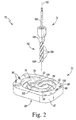
- the surgical instrument system 70 shown in FIG. 2 may be used to define a cavity in the proximal end of a patient's tibia that is sized and shaped to receive the cone implant 12.
- the cone implant 12 is formed from an implantable metallic material such as, for example, stainless steel, cobalt chromium, titanium, and may be secured to the patient's tibia via use of bone adhesive or other attachment means.
- the cone implant 12 is annular in shape, and includes a proximal rim surface 16, a distal rim surface 18, and a sidewall 20 extending between the two rim surfaces 16, 18.
- the sidewall 20 has a number of pores 22 defined therein, which are configured to permit bone ingrowth when the implant 12 is implanted in a patient's bone.
- the sidewall 20 includes an anterior section 24 and a posterior section 26 that are substantially straight.
- the sections 24, 26 connect a medial section 28 and a lateral section 30 of the sidewall 20.
- the sections 28, 30 are curved.
- the sections 24, 26, 28, 30 of the sidewall 20 are tapered such that the geometry of the implant 12 generally conforms to the geometry of the patient's tibia.
- the implant 12 has a proximal maximum medial-lateral width that is greater than its distal maximum medial-lateral width of the cone implant 12.
- the implant 12 also includes a pair of notches 36, 38 that are formed in the medial and lateral sections 28, 30, respectively.
- the notches 36, 38 are sized to accommodate the keels (not shown) protruding from the bottom of the tibial tray 14. It should be appreciated that one or both of the notches 36, 38 may be omitted. It is also envisaged that the cone implant 12 may be stepped.
- the tibial tray 14 is configured to be positioned proximal of the cone implant 12.
- the tibial tray 14, like the cone implant 12, may be secured to the patient's tibia via use of bone adhesive or other attachment means.
- the tibial tray 14 is formed from an implantable metallic material such as, for example, stainless steel, cobalt chromium, or titanium.
- the tibial tray 14 includes a platform 50 having a top surface 52 and a bottom surface 54. Illustratively, the top surface 52 is generally planar and might optionally be highly polished.
- the tibial tray 14 also includes a stem 56 extending downwardly from the bottom surface of the platform 50.
- a number of support buttresses 58 extend upwardly from the top surface 52, and each buttress 58 is configured to engage a tibial insert shaped to engage a femoral prosthetic component.
- a cavity or bore 60 is defined in one of the buttresses 58 and extends downwardly into the stem 56. The bore 60 is formed to receive a complimentary stem of the tibial insert.
- FIG. 2 shows an orthopaedic surgical instrument system 70 for use in preparing a patient's bone to receive the orthopaedic prosthesis 10.
- the device shown in Figure 2 includes a cutting guide block 72 and a cutting tool 74 for use with the cutting guide block 72.
- the cutting guide block 72 includes a cutting guide slot 76 that is sized and shaped to receive the cutting tool 74 and guide the cutting tool 74 to define a cavity that is sized to receive an implant cone 12.
- the cutting guide block 72 includes a superior surface 78, an inferior surface 80 positioned opposite the superior surface 78, and an outer sidewall 82 extending between the two surfaces 78, 80.
- the surfaces 78, 80 are substantially planar surfaces that extend parallel to one another and define imaginary planes 84, 86 (see FIG. 5 ), which will be discussed below with reference to other features of the cutting guide block 72.
- the cutting guide slot 76 extends through the surfaces 78, 80.
- the cutting guide block 72 is formed from a semi-transparent polymeric material, which permits a surgeon to monitor the cut being made in the patient's bone while also reducing the glare that can be reflected by the cutting guide block 72 when it is placed under bright surgical lights.
- suitable semi-transparent polymeric materials are a polyetherimide such as for example, that sold under the trade mark Ultem, or a polycarbonate such as, for example, that sold under the trade mark Lexan.
- the cutting guide block 72 may be different sizes to fit different sizes of bone, allowing a surgeon to resect a cavity of the correct size in the tibia of the patient.
- the cutting guide block 72 also includes a number of fixation pin guides 88 that extend through both the surfaces 78, 80.
- Each pin guide 88 is sized to receive a bone pin (not shown) to secure the cutting guide block 72 to the patient's bone.
- the pin guides 88 extend through the cutting guide block 72 at a non-orthogonal, or non-perpendicular, angle relative to the surfaces 78, 80.
- the cutting guide slot 76 of the cutting guide block 72 is sized and shaped to receive the cutting tool 74 and guide the cutting tool 74 to define a cavity that is sized to receive an implant cone 12.
- the block 72 includes an opening 90 that is defined in the superior surface 78 and an opening 92 that is defined in the inferior surface 80.
- a pair of inner walls 94, 96 extends between the openings 90, 92 to define the cutting guide slot 76 in the block 72.
- the slot 76 extends through the cutting guide block 72 such that the block 72 is divided into an outer body 100, an inner body 102, and a bridging section 104 positioned on the anterior side of the block 72 that connects the bodies 100, 102.
- the outer body 100 includes the inner wall 94, while the inner body 102 includes the opposite inner wall 96.
- the cutting guide slot 76 defines a guideway 106 that extends from an end 108 located near the centre of the block 72 to another end 110 positioned adjacent the anterior side of the block 72.
- the guideway 106 defines a cutting path, which the cutting tool 74 follows when resecting a patient's bone.
- the guideway 106 is configured to change the pitch or angle of the cutting tool 74 when it is resecting the patient's bone such that the cutting tool 74 defines a tapered cavity corresponding to the tapered sidewall 20 of the cone implant 12. To do so, the pitch or angle of the guideway 106 relative to the imaginary plane 86 (and hence the inferior surface 80) is adjusted between the ends 108, 110 of the cutting guide slot 76, as shown in FIGS. 6 to 9 and described below.
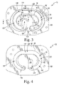
- the guideway 106 is defined by a number of slot sections that vary in pitch relative to the imaginary plane 86. As shown in FIGS. 3 and 4 , for example, the guideway 106 includes a slot section 114 that extends anteriorly from the end 108 of the cutting guide slot 76. In the device shown in the drawing, the section 114 defines a substantially straight cutting path. Another slot section 116 of the guideway 106 extends laterally from the end 110 of the cutting guide slot 76. The slot section 116, like the slot section 114, defines a substantially straight cutting path.
- Another slot section 118 connects the sections 114, 116, as shown in FIGS. 3 and 4 .
- the slot section 118 includes a posterior section 120 that extends in a medial-lateral direction and defines a substantially straight cutting path for the cutting tool 74.
- the slot section 118 also includes a pair of arced sections 122, 124 that connect the posterior section 120 with the slot sections 114, 116, respectively.
- the configuration of the arced section 122 mirrors the configuration of the arced section 124. It should be appreciated that the configuration of the guideway 106 may be adjusted based on the shape of the cone implant 12.
- FIGS. 6 to 9 show the cutting guide slot 76 in a number of cross-sectional planes 130 extending perpendicular to the surfaces 78, 80 (and hence planes 84, 86) of the cutting block 72 at various points along the slot 76.
- the slot 76 is defined by a pair of inner walls 94, 96 extending from a superior opening 90 to an inferior opening 92.
- the inner wall 94 extends from a superior edge 132 that partially defines the superior opening 90 to an inferior edge 134 that partially defines the inferior opening 92.
- the inner wall 94 includes a curved surface 136 that extends inwardly from the edge 132 to a transition surface 138 positioned between the surfaces 78, 80.
- Another surface 140 extends from the transition surface 138 to the inferior edge 134.
- the surface 140 defines a substantially straight line 142 when viewed in any of the cross-sectional planes 130.
- the inner wall 96 extends from a superior edge 150 that partially defines the superior opening 90 to an inferior edge 152 that partially defines the inferior opening 92.
- the inner wall 96 includes a curved surface 154 that extends inwardly from the edge 150 to a transition surface 156 positioned between the surfaces 78, 80.
- Another surface 158 extends from the transition surface 156 to the inferior edge 152.
- the surface 158 defines a substantially straight line 160 when viewed in any of the cross-sectional planes 130.
- the line 160 defined by the surface 158 of the inner wall 96 extends parallel to the line 142 defined by the surface 140 of the inner wall 94.
- a width 170 of the opening 90 is defined between the superior edges 132, 150 in each of the cross sectional planes 130.
- a width 172 of the opening 92 is also defined between the inferior edges 134, 152 in each of the cross sectional planes 130.
- the width 170 is the superior width of the cutting guide slot 76, while the width 172 is the inferior width of the cutting guide slot 76.
- the superior width 170 is greater than the inferior width 172 of the slot 76.
- the widths 170, 172 are sized to capture the cutting tool 74 and ensure that the cutting tool 74 does not extend into the bone beyond a predetermined depth.
- the widths 170, 172 may not be constant along the length of the guideway 106 and may vary between each of the cross sectional planes 130 shown in FIGS. 6 to 9 .
- the cutting guide slot 76 has a central axis 174 that is positioned between the inner walls 94, 96. In each of the cross sectional planes 130, the central axis 174 extends parallel to the inferior surfaces 140, 158 of the walls 94, 96, respectively. As described above, the pitch or angle of the guideway 106 relative to the imaginary plane 86 (and hence the inferior surface 80) is adjusted between the ends 108, 110 of the cutting guide slot 76. In the device shown in the drawing, the varying pitch or angle of the guideway 106 is apparent from the non-constant angles defined between the central axis 174 of the slot 76 and the imaginary plane 86 in the cross sectional planes 130 shown in FIGS.
- FIG. 6 which is a cross section of the slot 76 taken in an anterior-posterior direction at the end 110 of the slot 76, an angle ⁇ is defined between the central axis 174 and the imaginary plane 86.
- the angle ⁇ has a magnitude that is slightly less than 90° such that the guideway 106 is pitched inwardly (and hence away from the outer edge of the patient's bone when the block 72 is attached thereto). In that way, the pitch of the guideway 106 at that location corresponds to the taper of the cone implant 12.
- an angle ⁇ is defined between the central axis 174 and the imaginary plane 86. Because the end 108 is positioned near the center of the block 72 (and hence the center of the patient's bone when the block 72 is attached thereto), it is not necessary for the guideway 106 to be pitched at an angle, and, in the device shown in the drawing, the angle ⁇ has a magnitude that is approximately 90°.
- an angle ⁇ is defined between the central axis 174 and the imaginary plane 86.
- the angle ⁇ has a magnitude that is slightly less than 90° such that the guideway 106 is pitched inwardly (and hence away from the outer edge of the patient's bone when the block 72 is attached thereto). In that way, the pitch of the guideway 106 at that location corresponds to the taper of the cone implant 12.
- an angle ⁇ is defined between the central axis 174 and the imaginary plane 86.
- the angle ⁇ is less than 90° such that the guideway 106 is pitched inwardly (and hence away from the outer edge of the patient's bone when the block 72 is attached thereto).
- the angle ⁇ has a magnitude that is less than the angles ⁇ , ⁇ .
- the magnitude of the angle ⁇ is in a range of 30° to 70°.
- the surgical instrument system 70 also includes a cutting tool 74 that may be used with the cutting guide block 72.
- the cutting tool 74 is a burring tool.
- the tool 74 may instead be reamer, surgical drill, cutting saw blade, or other cutting tool.
- the system 70 may include multiple cutting tools of different lengths to resect different amounts from the patient's bone.
- the system 70 may include cutting guide blocks 72 of different sizes to accommodate different sizes of patient bones.
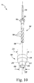
- the cutting tool 74 includes a shank 180 configured to be engaged by a rotary power tool, and a shaft 182 extending distally from the shank 180.
- the shaft 182 has a plurality of cutting flutes 184 defined at its distal end 186, which are configured to resect the patient's bone.
- the cutting tool 74 further includes an outer sleeve 188 that is pivotally coupled to the shaft 182 such that the shaft 182 and the shank 180 are permitted to rotate about the tool's longitudinal axis 190 relative to the sleeve 188, as described in greater detail below.
- the shank 180 of the cutting tool 74 includes a flange 192 that extends outwardly from its distal end 194.
- the flange 192 provides a stop for the outer sleeve 188 to keep the sleeve 188 engaged with the shaft 182.
- the sleeve 188 includes a body 200 that has a central passageway 202 defined therein, which is sized to receive the shaft 182.
- the body 200 includes a cylindrical proximal section 204 that engages the flange 192 and a cylindrical distal section 206 that has a diameter 208 that is smaller than the diameter 210 of the proximal section 204.
- a curved, beveled section 212 connects the sections 204, 206.
- the cutting tool 74 also includes a pair of roller bearings 214 that are positioned in the proximal section 204 of the sleeve 188.
- the roller bearings 214 are press-fit into the sleeve 188 and press-fit onto the shaft 182.
- the roller bearings 214 are configured to permit relative rotation between the outer sleeve 188 and the shaft 182 and the shank 180.
- the shank 180 and shaft 182 are formed as a single monolithic component from a stainless steel or other metallic material.
- the sleeve 188 is also formed from a metallic material such as, for example, stainless steel. Other materials may be used.
- the sleeve 188 may be formed from a plastic or polymeric material.
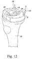
- FIGS. 12 to 16 show how the system 70 can be used to prepare a proximal end 220 of a patient's tibia 222 to receive a cone implant 12.
- a reciprocating cutting saw or other cutting tool may be used to create a substantially planar surface 224 on the proximal end 220, as shown in FIG. 12 .
- a surgeon or other user may then place the cutting block 72 on the surface 224.
- the surgeon may advance one or more fixation pins 226 through the fixation pin guides 88 in the block 72. Because the block 72 is formed from a semi-transparent material, the surgeon may monitor the position of the pin tips by looking through the block 72.
- the surgeon may advance the distal end 186 of the cutting tool 74 into the cutting guide slot 76 and into contact with the patient's tibia 222.
- the surgeon may first advance the cutting tool 74 into the end 108 of the cutting guide slot 76.
- the distal end 186 of the cutting tool 74 may extend outwardly from the inferior opening 92 of the slot 76 and into the intramedullary canal (not shown) of the tibia 222.
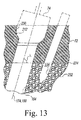
- the surgeon may continue to advance the cutting tool 74 into the guide slot 76 until the bevelled section 212 of the cutting tool's outer sleeve 188 is engaged with the transition surfaces 138, 156 of the cutting block 72, which define a bevelled groove 230 sized to receive it (see FIG. 13 ).
- the cutting tool's longitudinal axis 190 is coincident with the central axis 174 of the slot 76.
- the surgeon may then activate a rotary power tool to cause the shank 180 (and hence the cutting flutes 184) to rotate about the cutting tool's longitudinal axis 190. Because the outer sleeve 188 is pivotally coupled to the shank 180 and the shaft 182, the outer sleeve 188 is isolated from the power tool and does not rotate. While the cutting flutes 184 are rotating and the outer sleeve 188 engaged with the transition surfaces 138, 156, the surgeon may advance the cutting tool 74 anteriorly along the slot section 114 and into contact with the patient's bone. When the surgeon reaches the end of the slot section 114, the surgeon may continue to advance the cutting tool 74 along the arced section 122.
- the pitch of the cutting tool 74 (and hence the cutting angle) changes.
- FIG. 13 when a cross section of the slot 76 taken in a medial-lateral direction with the cutting tool 74 is located in the arced section 122, the cutting tool 74 is pitched away from the outer edge 232 of the tibia 222 at the angle ⁇ , which matches the taper of the cone implant 12 at that position relative to the patient's bone.
- the same angle ⁇ is defined between the cutting tool's longitudinal axis 190 and the resected surface 224.
- the pitch of the cutting tool 74 is changed.
- FIG. 14 which is a cross section of the slot 76 taken in an anterior-posterior direction in the posterior section 120 of the slot 76
- the cutting tool 74 is pitched at the angle ⁇ , which matches the taper of the cone implant 12 at that position relative to the patient's bone.
- the same angle ⁇ is defined between the cutting tool's longitudinal axis 190 and the resected surface 224.
- the pitch of the cutting tool 74 changes to match the corresponding changing taper of the cone implant 12.
- the pitch (and hence the cutting angle) first decreases, then increases, then decreases again, before finally increasing back to slightly less than 90° as the cutting tool 74 is advanced from the end 108 to the end 110 of the cutting guide slot 76.
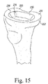
- a cavity 234 is defined in the surface 220 of the patient's tibia 222, and the cutting tool 74 and the cutting guide block 72 may be removed from the patient's tibia 222.
- the cavity 234 is defined by a number of walls 236 that are shaped to match the outer geometry of the cone implant 12. As shown in FIG. 16 , when the cone implant 12 is positioned in the cavity 234, the cone implant 12 fits snugly against the walls 236.
Landscapes
- Health & Medical Sciences (AREA)
- Surgery (AREA)
- Life Sciences & Earth Sciences (AREA)
- Medical Informatics (AREA)
- Animal Behavior & Ethology (AREA)
- Veterinary Medicine (AREA)
- Oral & Maxillofacial Surgery (AREA)
- Engineering & Computer Science (AREA)
- Biomedical Technology (AREA)
- Heart & Thoracic Surgery (AREA)
- Dentistry (AREA)
- Molecular Biology (AREA)
- Nuclear Medicine, Radiotherapy & Molecular Imaging (AREA)
- General Health & Medical Sciences (AREA)
- Public Health (AREA)
- Orthopedic Medicine & Surgery (AREA)
- Physical Education & Sports Medicine (AREA)
- Transplantation (AREA)
- Surgical Instruments (AREA)
- Prostheses (AREA)
Applications Claiming Priority (1)
| Application Number | Priority Date | Filing Date | Title |
|---|---|---|---|
| US14/788,052 US9999428B2 (en) | 2015-06-30 | 2015-06-30 | Orthopaedic surgical instrument system and method for surgically preparing a patients bone |
Publications (3)
| Publication Number | Publication Date |
|---|---|
| EP3146919A2 true EP3146919A2 (fr) | 2017-03-29 |
| EP3146919A3 EP3146919A3 (fr) | 2017-08-02 |
| EP3146919B1 EP3146919B1 (fr) | 2018-08-15 |
Family
ID=56289419
Family Applications (1)
| Application Number | Title | Priority Date | Filing Date |
|---|---|---|---|
| EP16176839.5A Not-in-force EP3146919B1 (fr) | 2015-06-30 | 2016-06-29 | Système d'instrument chirurgical orthopédique |
Country Status (5)
| Country | Link |
|---|---|
| US (3) | US9999428B2 (fr) |
| EP (1) | EP3146919B1 (fr) |
| JP (1) | JP6887763B2 (fr) |
| CN (1) | CN106308875A (fr) |
| AU (1) | AU2016204358B9 (fr) |
Families Citing this family (17)
| Publication number | Priority date | Publication date | Assignee | Title |
|---|---|---|---|---|
| US9999428B2 (en) | 2015-06-30 | 2018-06-19 | DePuy Synthes Products, Inc. | Orthopaedic surgical instrument system and method for surgically preparing a patients bone |
| US11007035B2 (en) | 2017-03-16 | 2021-05-18 | Viax Dental Technologies Llc | System for preparing teeth for the placement of veneers |
| US10987225B2 (en) | 2017-08-04 | 2021-04-27 | Zimmer, Inc. | Systems and methods for attaching sleeve or cone in prosthetic implant having a stem |
| EP3694446B1 (fr) | 2017-10-11 | 2022-12-21 | Zimmer, Inc. | Berceau d'impact |
| EP4248886B1 (fr) | 2017-10-13 | 2026-03-11 | Zimmer, Inc. | Instruments d'arthroplastie du genou de révision |
| EP3501432A1 (fr) | 2017-12-20 | 2019-06-26 | Stryker European Holdings I, LLC | Instrumentation pour articulation |
| EP3520739B1 (fr) | 2018-02-06 | 2020-12-02 | Tornier | Procédé de fabrication d'une prothèse spécifique au patient pour un os long fracturé |
| SG11202107144TA (en) * | 2019-01-04 | 2021-07-29 | Viax Dental Tech Llc | Tooth preparation system with lateral prongs for limiting three-dimensional movement |
| US20230088873A1 (en) * | 2019-02-28 | 2023-03-23 | Icahn School Of Medicine At Mount Sinai | Customized tibial trays, methods, and systems for knee replacement |
| EP4081168A4 (fr) * | 2020-03-25 | 2024-03-20 | Howmedica Osteonics Corp. | Technique et instrument de référencement métaphysaire |
| US12364489B2 (en) * | 2020-06-30 | 2025-07-22 | The Johns Hopkins University | System and method for fixing a cranial implant |
| CN113040863B (zh) * | 2021-03-09 | 2022-08-26 | 四川大学华西医院 | 一种结合超声骨刀的颈椎前路截骨用导航系统 |
| US12369930B2 (en) | 2022-06-20 | 2025-07-29 | Zimmer, Inc. | Systems for guided reaming of complex shapes |
| JP7510481B2 (ja) * | 2022-11-28 | 2024-07-03 | 財團法人金屬工業研究發展中心 | 手術器具 |
| US20240207062A1 (en) | 2022-12-22 | 2024-06-27 | Zimmer, Inc. | Segmented keel for prosthetic implant having a stem |
| CN116492004B (zh) * | 2023-03-29 | 2025-12-19 | 北京市春立正达医疗器械股份有限公司 | 多功能膝关节股骨四合一截骨装置 |
| WO2025217154A1 (fr) * | 2024-04-08 | 2025-10-16 | Mayo Foundation For Medical Education And Research | Système de conception et d'instrumentation d'implants sur mesure |
Family Cites Families (28)
| Publication number | Priority date | Publication date | Assignee | Title |
|---|---|---|---|---|
| US684693A (en) | 1901-01-31 | 1901-10-15 | John W Jenkins | Railway system. |
| US4790852A (en) | 1986-09-15 | 1988-12-13 | Joint Medical Products Corporation | Sleeves for affixing artificial joints to bone |
| US5344423A (en) * | 1992-02-06 | 1994-09-06 | Zimmer, Inc. | Apparatus and method for milling bone |
| US5908424A (en) * | 1994-05-16 | 1999-06-01 | Zimmer, Inc, By Said Stalcup, Dietz, Bays And Vanlaningham | Tibial milling guide system |
| US5716361A (en) * | 1995-11-02 | 1998-02-10 | Masini; Michael A. | Bone cutting guides for use in the implantation of prosthetic joint components |
| US6554838B2 (en) * | 2001-05-31 | 2003-04-29 | Howmedica Osteonics Corp. | Method and apparatus for implanting a prosthetic device |
| US20030065397A1 (en) | 2001-08-27 | 2003-04-03 | Hanssen Arlen D. | Prosthetic implant support structure |
| US7892288B2 (en) | 2001-08-27 | 2011-02-22 | Zimmer Technology, Inc. | Femoral augments for use with knee joint prosthesis |
| US20040162619A1 (en) | 2001-08-27 | 2004-08-19 | Zimmer Technology, Inc. | Tibial augments for use with knee joint prostheses, method of implanting the tibial augment, and associated tools |
| US8211113B2 (en) * | 2002-06-21 | 2012-07-03 | Depuy Products, Inc. | Prosthesis cutting guide, cutting tool and method |
| USD684693S1 (en) | 2002-08-22 | 2013-06-18 | Zimmer, Inc. | Prosthetic implant support structure |
| US6994730B2 (en) * | 2003-01-31 | 2006-02-07 | Howmedica Osteonics Corp. | Meniscal and tibial implants |
| FR2856268B1 (fr) * | 2003-06-18 | 2005-10-21 | Perception Raisonnement Action | Dispositif de guidage de coupe osseuse |
| US20050192588A1 (en) * | 2004-02-27 | 2005-09-01 | Garcia Daniel X. | Instrumentation and method for prosthetic knee |
| US20060089621A1 (en) * | 2004-03-18 | 2006-04-27 | Mike Fard | Bone mill and template |
| JP4944103B2 (ja) * | 2005-05-20 | 2012-05-30 | スミス アンド ネフュー インコーポレーテッド | 膝蓋大腿関節インプラント及び器具 |
| US7695477B2 (en) * | 2005-05-26 | 2010-04-13 | Zimmer, Inc. | Milling system and methods for resecting a joint articulation surface |
| US7727239B2 (en) * | 2005-06-10 | 2010-06-01 | Zimmer Technology, Inc. | Milling system with guide paths and related methods for resecting a joint articulation surface |
| US8313490B2 (en) * | 2007-03-16 | 2012-11-20 | Zimmer Technology, Inc. | Single plane anatomic referencing tissue preparation |
| EP2334243B1 (fr) * | 2008-08-01 | 2016-12-07 | DePuy Products, Inc. | Instruments de chirurgie orthopédique et procédé permettant de réaliser une opération d'arthroplastie fémoro-patellaire |
| US20100114323A1 (en) | 2008-10-31 | 2010-05-06 | Depuy Products, Inc. | Knee prosthesis kit with winged sleeves and milling guide |
| EP2493396B1 (fr) * | 2009-10-29 | 2016-11-23 | Zimmer, Inc. | Guide de fraisage spécifique d'un patient |
| GB2489033B (en) * | 2011-03-17 | 2016-05-25 | Biomet Uk Healthcare Ltd | Guide tool |
| CA2845018C (fr) * | 2011-08-12 | 2018-05-22 | Zimmer, Inc. | Guide de resection de prothese |
| ES2508518T3 (es) * | 2011-11-23 | 2014-10-16 | Waldemar Link Gmbh & Co. Kg | Dispositivo para la previsión de un plano de corte para la resección ósea |
| US9414847B2 (en) | 2012-10-21 | 2016-08-16 | William B. Kurtz | Patient specific soft tissue protectors and retractors |
| US9386999B2 (en) * | 2013-03-13 | 2016-07-12 | Depuy (Ireland) | Tibial orthopaedic surgical instruments for setting offset |
| US9999428B2 (en) | 2015-06-30 | 2018-06-19 | DePuy Synthes Products, Inc. | Orthopaedic surgical instrument system and method for surgically preparing a patients bone |
-
2015
- 2015-06-30 US US14/788,052 patent/US9999428B2/en active Active
-
2016
- 2016-06-24 AU AU2016204358A patent/AU2016204358B9/en not_active Expired - Fee Related
- 2016-06-29 JP JP2016128733A patent/JP6887763B2/ja not_active Expired - Fee Related
- 2016-06-29 EP EP16176839.5A patent/EP3146919B1/fr not_active Not-in-force
- 2016-06-30 CN CN201610507400.0A patent/CN106308875A/zh active Pending
-
2018
- 2018-06-19 US US16/011,899 patent/US10363051B2/en active Active
-
2019
- 2019-07-30 US US16/526,116 patent/US11006968B2/en not_active Expired - Fee Related
Non-Patent Citations (1)
| Title |
|---|
| None |
Also Published As
| Publication number | Publication date |
|---|---|
| US11006968B2 (en) | 2021-05-18 |
| AU2016204358B9 (en) | 2020-08-20 |
| AU2016204358A1 (en) | 2017-01-19 |
| US20170000503A1 (en) | 2017-01-05 |
| US20190350599A1 (en) | 2019-11-21 |
| JP6887763B2 (ja) | 2021-06-16 |
| EP3146919A3 (fr) | 2017-08-02 |
| EP3146919B1 (fr) | 2018-08-15 |
| US20180296230A1 (en) | 2018-10-18 |
| JP2017012756A (ja) | 2017-01-19 |
| US10363051B2 (en) | 2019-07-30 |
| CN106308875A (zh) | 2017-01-11 |
| AU2016204358B2 (en) | 2020-08-13 |
| US9999428B2 (en) | 2018-06-19 |
Similar Documents
| Publication | Publication Date | Title |
|---|---|---|
| US11006968B2 (en) | Method and orthopaedic surgical instrument system for surgically preparing a patient's bone | |
| US20230338153A1 (en) | Partial joint resurfacing implant, instrumentation, and method | |
| US9265611B2 (en) | Partial joint resurfacing implant, instrumentation, and method | |
| EP2777626B1 (fr) | Système d'implantation d'une prothèse glénoïde secondaire | |
| US9737408B2 (en) | Tibial impaction guide surgical instrument and method of using same | |
| JP7150614B2 (ja) | 整形外科的関節置換手技における患者の大腿骨を準備するためのシステム及び方法 | |
| US20040153087A1 (en) | Provisional orthopedic implant with removable guide | |
| EP2422718A1 (fr) | Guide de fraisage pour l'implantation d'une prothèse de genou | |
| US20190247063A1 (en) | Orthopaedic surgical instrument system and method for preparing a patient's calcar | |
| EP2777553B1 (fr) | Ensemble instrument pour l'implantation d'une tige de prothèse de genou | |
| US20190247061A1 (en) | Orthopaedic surgical instrument system and method for preparing a patient's calcar | |
| GB2487562A (en) | A rotatry mill and guide for a unicondylar femoral component |
Legal Events
| Date | Code | Title | Description |
|---|---|---|---|
| PUAI | Public reference made under article 153(3) epc to a published international application that has entered the european phase |
Free format text: ORIGINAL CODE: 0009012 |
|
| STAA | Information on the status of an ep patent application or granted ep patent |
Free format text: STATUS: THE APPLICATION HAS BEEN PUBLISHED |
|
| PUAB | Information related to the publication of an a document modified or deleted |
Free format text: ORIGINAL CODE: 0009199EPPU |
|
| PUAI | Public reference made under article 153(3) epc to a published international application that has entered the european phase |
Free format text: ORIGINAL CODE: 0009012 |
|
| AK | Designated contracting states |
Kind code of ref document: A2 Designated state(s): AL AT BE BG CH CY CZ DE DK EE ES FI FR GB GR HR HU IE IS IT LI LT LU LV MC MK MT NL NO PL PT RO RS SE SI SK SM TR |
|
| AX | Request for extension of the european patent |
Extension state: BA ME |
|
| PUAL | Search report despatched |
Free format text: ORIGINAL CODE: 0009013 |
|
| AK | Designated contracting states |
Kind code of ref document: A3 Designated state(s): AL AT BE BG CH CY CZ DE DK EE ES FI FR GB GR HR HU IE IS IT LI LT LU LV MC MK MT NL NO PL PT RO RS SE SI SK SM TR |
|
| AX | Request for extension of the european patent |
Extension state: BA ME |
|
| RIC1 | Information provided on ipc code assigned before grant |
Ipc: A61B 17/16 20060101ALI20170623BHEP Ipc: A61B 17/17 20060101AFI20170623BHEP |
|
| STAA | Information on the status of an ep patent application or granted ep patent |
Free format text: STATUS: REQUEST FOR EXAMINATION WAS MADE |
|
| RAP1 | Party data changed (applicant data changed or rights of an application transferred) |
Owner name: DEPUY IRELAND UNLIMITED COMPANY |
|
| 17P | Request for examination filed |
Effective date: 20171102 |
|
| RBV | Designated contracting states (corrected) |
Designated state(s): AL AT BE BG CH CY CZ DE DK EE ES FI FR GB GR HR HU IE IS IT LI LT LU LV MC MK MT NL NO PL PT RO RS SE SI SK SM TR |
|
| GRAP | Despatch of communication of intention to grant a patent |
Free format text: ORIGINAL CODE: EPIDOSNIGR1 |
|
| STAA | Information on the status of an ep patent application or granted ep patent |
Free format text: STATUS: GRANT OF PATENT IS INTENDED |
|
| INTG | Intention to grant announced |
Effective date: 20180312 |
|
| GRAS | Grant fee paid |
Free format text: ORIGINAL CODE: EPIDOSNIGR3 |
|
| GRAA | (expected) grant |
Free format text: ORIGINAL CODE: 0009210 |
|
| STAA | Information on the status of an ep patent application or granted ep patent |
Free format text: STATUS: THE PATENT HAS BEEN GRANTED |
|
| AK | Designated contracting states |
Kind code of ref document: B1 Designated state(s): AL AT BE BG CH CY CZ DE DK EE ES FI FR GB GR HR HU IE IS IT LI LT LU LV MC MK MT NL NO PL PT RO RS SE SI SK SM TR |
|
| REG | Reference to a national code |
Ref country code: CH Ref legal event code: EP Ref country code: GB Ref legal event code: FG4D Ref country code: AT Ref legal event code: REF Ref document number: 1028835 Country of ref document: AT Kind code of ref document: T Effective date: 20180815 |
|
| REG | Reference to a national code |
Ref country code: CH Ref legal event code: NV Representative=s name: E. BLUM AND CO. AG PATENT- UND MARKENANWAELTE , CH |
|
| REG | Reference to a national code |
Ref country code: IE Ref legal event code: FG4D |
|
| REG | Reference to a national code |
Ref country code: DE Ref legal event code: R096 Ref document number: 602016004734 Country of ref document: DE |
|
| REG | Reference to a national code |
Ref country code: NL Ref legal event code: MP Effective date: 20180815 |
|
| REG | Reference to a national code |
Ref country code: LT Ref legal event code: MG4D |
|
| REG | Reference to a national code |
Ref country code: AT Ref legal event code: MK05 Ref document number: 1028835 Country of ref document: AT Kind code of ref document: T Effective date: 20180815 |
|
| PG25 | Lapsed in a contracting state [announced via postgrant information from national office to epo] |
Ref country code: SE Free format text: LAPSE BECAUSE OF FAILURE TO SUBMIT A TRANSLATION OF THE DESCRIPTION OR TO PAY THE FEE WITHIN THE PRESCRIBED TIME-LIMIT Effective date: 20180815 Ref country code: BG Free format text: LAPSE BECAUSE OF FAILURE TO SUBMIT A TRANSLATION OF THE DESCRIPTION OR TO PAY THE FEE WITHIN THE PRESCRIBED TIME-LIMIT Effective date: 20181115 Ref country code: NL Free format text: LAPSE BECAUSE OF FAILURE TO SUBMIT A TRANSLATION OF THE DESCRIPTION OR TO PAY THE FEE WITHIN THE PRESCRIBED TIME-LIMIT Effective date: 20180815 Ref country code: LT Free format text: LAPSE BECAUSE OF FAILURE TO SUBMIT A TRANSLATION OF THE DESCRIPTION OR TO PAY THE FEE WITHIN THE PRESCRIBED TIME-LIMIT Effective date: 20180815 Ref country code: FI Free format text: LAPSE BECAUSE OF FAILURE TO SUBMIT A TRANSLATION OF THE DESCRIPTION OR TO PAY THE FEE WITHIN THE PRESCRIBED TIME-LIMIT Effective date: 20180815 Ref country code: AT Free format text: LAPSE BECAUSE OF FAILURE TO SUBMIT A TRANSLATION OF THE DESCRIPTION OR TO PAY THE FEE WITHIN THE PRESCRIBED TIME-LIMIT Effective date: 20180815 Ref country code: IS Free format text: LAPSE BECAUSE OF FAILURE TO SUBMIT A TRANSLATION OF THE DESCRIPTION OR TO PAY THE FEE WITHIN THE PRESCRIBED TIME-LIMIT Effective date: 20181215 Ref country code: NO Free format text: LAPSE BECAUSE OF FAILURE TO SUBMIT A TRANSLATION OF THE DESCRIPTION OR TO PAY THE FEE WITHIN THE PRESCRIBED TIME-LIMIT Effective date: 20181115 Ref country code: RS Free format text: LAPSE BECAUSE OF FAILURE TO SUBMIT A TRANSLATION OF THE DESCRIPTION OR TO PAY THE FEE WITHIN THE PRESCRIBED TIME-LIMIT Effective date: 20180815 Ref country code: GR Free format text: LAPSE BECAUSE OF FAILURE TO SUBMIT A TRANSLATION OF THE DESCRIPTION OR TO PAY THE FEE WITHIN THE PRESCRIBED TIME-LIMIT Effective date: 20181116 |
|
| PG25 | Lapsed in a contracting state [announced via postgrant information from national office to epo] |
Ref country code: AL Free format text: LAPSE BECAUSE OF FAILURE TO SUBMIT A TRANSLATION OF THE DESCRIPTION OR TO PAY THE FEE WITHIN THE PRESCRIBED TIME-LIMIT Effective date: 20180815 Ref country code: HR Free format text: LAPSE BECAUSE OF FAILURE TO SUBMIT A TRANSLATION OF THE DESCRIPTION OR TO PAY THE FEE WITHIN THE PRESCRIBED TIME-LIMIT Effective date: 20180815 Ref country code: LV Free format text: LAPSE BECAUSE OF FAILURE TO SUBMIT A TRANSLATION OF THE DESCRIPTION OR TO PAY THE FEE WITHIN THE PRESCRIBED TIME-LIMIT Effective date: 20180815 |
|
| PG25 | Lapsed in a contracting state [announced via postgrant information from national office to epo] |
Ref country code: EE Free format text: LAPSE BECAUSE OF FAILURE TO SUBMIT A TRANSLATION OF THE DESCRIPTION OR TO PAY THE FEE WITHIN THE PRESCRIBED TIME-LIMIT Effective date: 20180815 Ref country code: PL Free format text: LAPSE BECAUSE OF FAILURE TO SUBMIT A TRANSLATION OF THE DESCRIPTION OR TO PAY THE FEE WITHIN THE PRESCRIBED TIME-LIMIT Effective date: 20180815 Ref country code: IT Free format text: LAPSE BECAUSE OF FAILURE TO SUBMIT A TRANSLATION OF THE DESCRIPTION OR TO PAY THE FEE WITHIN THE PRESCRIBED TIME-LIMIT Effective date: 20180815 Ref country code: CZ Free format text: LAPSE BECAUSE OF FAILURE TO SUBMIT A TRANSLATION OF THE DESCRIPTION OR TO PAY THE FEE WITHIN THE PRESCRIBED TIME-LIMIT Effective date: 20180815 Ref country code: RO Free format text: LAPSE BECAUSE OF FAILURE TO SUBMIT A TRANSLATION OF THE DESCRIPTION OR TO PAY THE FEE WITHIN THE PRESCRIBED TIME-LIMIT Effective date: 20180815 Ref country code: ES Free format text: LAPSE BECAUSE OF FAILURE TO SUBMIT A TRANSLATION OF THE DESCRIPTION OR TO PAY THE FEE WITHIN THE PRESCRIBED TIME-LIMIT Effective date: 20180815 |
|
| REG | Reference to a national code |
Ref country code: DE Ref legal event code: R097 Ref document number: 602016004734 Country of ref document: DE |
|
| PG25 | Lapsed in a contracting state [announced via postgrant information from national office to epo] |
Ref country code: SK Free format text: LAPSE BECAUSE OF FAILURE TO SUBMIT A TRANSLATION OF THE DESCRIPTION OR TO PAY THE FEE WITHIN THE PRESCRIBED TIME-LIMIT Effective date: 20180815 Ref country code: SM Free format text: LAPSE BECAUSE OF FAILURE TO SUBMIT A TRANSLATION OF THE DESCRIPTION OR TO PAY THE FEE WITHIN THE PRESCRIBED TIME-LIMIT Effective date: 20180815 Ref country code: DK Free format text: LAPSE BECAUSE OF FAILURE TO SUBMIT A TRANSLATION OF THE DESCRIPTION OR TO PAY THE FEE WITHIN THE PRESCRIBED TIME-LIMIT Effective date: 20180815 |
|
| PLBE | No opposition filed within time limit |
Free format text: ORIGINAL CODE: 0009261 |
|
| STAA | Information on the status of an ep patent application or granted ep patent |
Free format text: STATUS: NO OPPOSITION FILED WITHIN TIME LIMIT |
|
| 26N | No opposition filed |
Effective date: 20190516 |
|
| PG25 | Lapsed in a contracting state [announced via postgrant information from national office to epo] |
Ref country code: SI Free format text: LAPSE BECAUSE OF FAILURE TO SUBMIT A TRANSLATION OF THE DESCRIPTION OR TO PAY THE FEE WITHIN THE PRESCRIBED TIME-LIMIT Effective date: 20180815 |
|
| PG25 | Lapsed in a contracting state [announced via postgrant information from national office to epo] |
Ref country code: MC Free format text: LAPSE BECAUSE OF FAILURE TO SUBMIT A TRANSLATION OF THE DESCRIPTION OR TO PAY THE FEE WITHIN THE PRESCRIBED TIME-LIMIT Effective date: 20180815 |
|
| REG | Reference to a national code |
Ref country code: BE Ref legal event code: MM Effective date: 20190630 |
|
| PG25 | Lapsed in a contracting state [announced via postgrant information from national office to epo] |
Ref country code: TR Free format text: LAPSE BECAUSE OF FAILURE TO SUBMIT A TRANSLATION OF THE DESCRIPTION OR TO PAY THE FEE WITHIN THE PRESCRIBED TIME-LIMIT Effective date: 20180815 |
|
| PG25 | Lapsed in a contracting state [announced via postgrant information from national office to epo] |
Ref country code: BE Free format text: LAPSE BECAUSE OF NON-PAYMENT OF DUE FEES Effective date: 20190630 Ref country code: LU Free format text: LAPSE BECAUSE OF NON-PAYMENT OF DUE FEES Effective date: 20190629 |
|
| PG25 | Lapsed in a contracting state [announced via postgrant information from national office to epo] |
Ref country code: PT Free format text: LAPSE BECAUSE OF FAILURE TO SUBMIT A TRANSLATION OF THE DESCRIPTION OR TO PAY THE FEE WITHIN THE PRESCRIBED TIME-LIMIT Effective date: 20181215 |
|
| PGFP | Annual fee paid to national office [announced via postgrant information from national office to epo] |
Ref country code: IE Payment date: 20200609 Year of fee payment: 5 Ref country code: DE Payment date: 20200617 Year of fee payment: 5 Ref country code: CH Payment date: 20200616 Year of fee payment: 5 Ref country code: FR Payment date: 20200512 Year of fee payment: 5 |
|
| PGFP | Annual fee paid to national office [announced via postgrant information from national office to epo] |
Ref country code: GB Payment date: 20200617 Year of fee payment: 5 |
|
| PG25 | Lapsed in a contracting state [announced via postgrant information from national office to epo] |
Ref country code: CY Free format text: LAPSE BECAUSE OF FAILURE TO SUBMIT A TRANSLATION OF THE DESCRIPTION OR TO PAY THE FEE WITHIN THE PRESCRIBED TIME-LIMIT Effective date: 20180815 |
|
| PG25 | Lapsed in a contracting state [announced via postgrant information from national office to epo] |
Ref country code: HU Free format text: LAPSE BECAUSE OF FAILURE TO SUBMIT A TRANSLATION OF THE DESCRIPTION OR TO PAY THE FEE WITHIN THE PRESCRIBED TIME-LIMIT; INVALID AB INITIO Effective date: 20160629 Ref country code: MT Free format text: LAPSE BECAUSE OF FAILURE TO SUBMIT A TRANSLATION OF THE DESCRIPTION OR TO PAY THE FEE WITHIN THE PRESCRIBED TIME-LIMIT Effective date: 20180815 |
|
| REG | Reference to a national code |
Ref country code: DE Ref legal event code: R119 Ref document number: 602016004734 Country of ref document: DE |
|
| REG | Reference to a national code |
Ref country code: CH Ref legal event code: PL |
|
| GBPC | Gb: european patent ceased through non-payment of renewal fee |
Effective date: 20210629 |
|
| PG25 | Lapsed in a contracting state [announced via postgrant information from national office to epo] |
Ref country code: LI Free format text: LAPSE BECAUSE OF NON-PAYMENT OF DUE FEES Effective date: 20210630 Ref country code: IE Free format text: LAPSE BECAUSE OF NON-PAYMENT OF DUE FEES Effective date: 20210629 Ref country code: GB Free format text: LAPSE BECAUSE OF NON-PAYMENT OF DUE FEES Effective date: 20210629 Ref country code: DE Free format text: LAPSE BECAUSE OF NON-PAYMENT OF DUE FEES Effective date: 20220101 Ref country code: CH Free format text: LAPSE BECAUSE OF NON-PAYMENT OF DUE FEES Effective date: 20210630 |
|
| PG25 | Lapsed in a contracting state [announced via postgrant information from national office to epo] |
Ref country code: FR Free format text: LAPSE BECAUSE OF NON-PAYMENT OF DUE FEES Effective date: 20210630 |
|
| PG25 | Lapsed in a contracting state [announced via postgrant information from national office to epo] |
Ref country code: MK Free format text: LAPSE BECAUSE OF FAILURE TO SUBMIT A TRANSLATION OF THE DESCRIPTION OR TO PAY THE FEE WITHIN THE PRESCRIBED TIME-LIMIT Effective date: 20180815 |