EP3147007B1 - Dispositif de lancement combiné pour lancer des toupies - Google Patents
Dispositif de lancement combiné pour lancer des toupies Download PDFInfo
- Publication number
- EP3147007B1 EP3147007B1 EP16170807.8A EP16170807A EP3147007B1 EP 3147007 B1 EP3147007 B1 EP 3147007B1 EP 16170807 A EP16170807 A EP 16170807A EP 3147007 B1 EP3147007 B1 EP 3147007B1
- Authority
- EP
- European Patent Office
- Prior art keywords
- launching
- spinning
- combined
- spinning top
- coupler
- Prior art date
- Legal status (The legal status is an assumption and is not a legal conclusion. Google has not performed a legal analysis and makes no representation as to the accuracy of the status listed.)
- Not-in-force
Links
Images

Classifications
-
- A—HUMAN NECESSITIES
- A63—SPORTS; GAMES; AMUSEMENTS
- A63H—TOYS, e.g. TOPS, DOLLS, HOOPS OR BUILDING BLOCKS
- A63H1/00—Tops
- A63H1/02—Tops with detachable winding devices
- A63H1/04—Tops with detachable winding devices with string or band winding devices
Definitions
- the present invention relates to a combined launching device for simultaneously launching a plurality of spinning tops.
- a traditional launching device for launching a spinning top is configured to launch only one spinning top from a spinning top holder.
- the user When a user plays a spinning-tops combat game alone, the user have to launch a first spinning top with a launching device and launch a second one immediately after the first one.
- Japanese Utility-Model Registration No. 3090580 discloses a launching device for simultaneously launching two spinning tops.
- the launching device for simultaneously launching two spinning tops includes a housing accommodating two launching units in parallel, each of which launches a spinning top. Inserting two rack belts into the respective launching units and then pulling the two rack belts together can simultaneously launch two spinning tops.
- JP H02 13595 (U ) describes a toy unit comprising a moveable toy and a flat rectangular toy case having a cavity disposed therein in which the toy is detachably set when not in use and support means disposed therein for supporting the toy while it is being powered by power generating means.
- the toy case is in the form of a thin generally rectangular block when the toy is in the cavity.
- the launching device disclosed in Japanese Utility-Model Registration No. 3090580 has a complicated structure including two launching units and a special housing for accommodating the two launching units in parallel.
- An object of the present invention is to provide a combined launching device with a simple structure for launching spinning tops.
- a combined launching device for launching spinning tops including:
- the operating member is a rack belt.
- two launching units can be separated for independent use of the individual launching units or the two launching units can be combined with each other for simultaneous launching of two spinning tops.
- the user can simultaneously launch two spinning tops and play a spinning-tops combat game alone with the combined launching units.
- This combined launching device has a simple structure.
- the first launching unit is combined with the second launching unit such that the rack belt is engaged with both of a pinion of the first spinning mechanism and a pinion of the second spinning mechanism.
- the combined launching units can be readily operated with one rack belt for simultaneous launching of two spinning tops.
- the first launching unit has both of the first coupler and the second coupler and the second launching unit has both of the first coupler and the second coupler.
- three or more launching units can be combined with each other.
- these launching units can be disposed in any direction in the combined launching device.
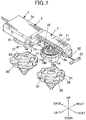
- Fig. 1 illustrates a combined launching device 1 including two launching units 2 combined in the longitudinal direction, for launching spinning tops.
- each launching unit 2 is loaded with one spinning top 30.
- the combined launching device 1 includes one rack belt 20.
- the rack belt 20 is introduced from the front launching unit 2 into the combined launching device 1 such that the front end of the rack belt 20 projects from the back launching unit 2. Pulling the rack belt 20 can simultaneously spin and launch the spinning tops 30 mounted in the launching units 2.
- the combined launching device 1 can be separated into the two launching units 2 for independent use of the individual launching units 2.
- the two launching units 2 have an identical structure. In the circumstances, the same reference numeral is used for identical elements of the two launching units 2 for avoiding redundancy in the description.
- the launching unit 2 includes a casing 2a.
- the casing 2a is generally rectangular in top view.
- the casing 2a is open at the bottom (see Fig. 2 ).
- the casing 2a has a forward projection 3a at the front end.
- the projection 3a is positioned in the middle of the front end of the casing 2a in the transverse or horizontal direction and is narrower than the casing 2a in the transverse direction.
- the projection 3a has a rib 30a on each side in the transverse direction.
- the ribs 30a project outwardly in the transverse direction.
- the projection 3a functions as a coupler.
- the casing 2a has a cutout 18a at the back end.
- the cutout 18a has substantially the same width as that of the projection 3a in the transverse direction.
- the cutout 18a is open to the bottom.
- a wall 18b is provided in front of the cutout 18a.
- the edges of the cutout 18a, the wall 18b, and the right and left walls define a recess 3b.
- the recess 3b functions as another coupler.
- the projection 3a of the back launching unit 2 When the projection 3a of the back launching unit 2 is fitted into the cutout 18a of the front launching unit 2 from the bottom, the front face of the projection 3a of the back launching unit 2 comes in contact with the wall 18b of the front launching unit 2 and the right and left ribs 30a of the back launching unit 2 interlock with the right and left edges, respectively, of the cutout 18a of the front launching unit 2.
- the two launching units 2 are thereby combined with each other. Releasing the projection 3a from the recess 3b causes the two launching units 2 to be separated from each other.
- the projection 3a has a belt inlet 4a for the rack belt 20 and the wall 18b has a belt outlet 4b for the rack belt 20.
- the belt inlet 4a and belt outlet 4b of one launching unit 2 are aligned to the belt inlet 4a and belt outlet 4b of the other launching unit 2.
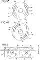
- the casing 2a includes a disk spinning top holder 15 to be loaded with a spinning top 30.
- the spinning top holder 15 is mounted on the casing 2a around a rotating shaft 11.
- the spinning top holder 15 can idle around the rotating shaft 11.
- the spinning top holder 15 has two clicks 16 disposed symmetrically around the rotating shaft 11 on the bottom periphery. Each click 16 is arc-shaped in bottom view.
- the click 16 has a flat face 16a at the bottom end, a vertical face 16b at the head end in the rotating direction, and an inclined face 16c at the tail end in the rotating direction.
- the casing 2a accommodates a spinning mechanism 10 for spinning the spinning top holder 15.
- the spinning mechanism 10 includes a pinion 12 and a clutch 13.
- the pinion 12 is fixed to the rotating shaft 11 and engageable with the teeth of the rack belt 20.
- the clutch 13 transmits rotative power from the pinion 12 to the spinning top holder 15.
- the clutch 13 rotates together with the pinion 12.
- the clutch 13 is composed of a synthetic resin.
- the clutch 13 includes a hub 13a engaged with the rotating shaft 11 and two C-shaped protrusions 13b integrated with the hub 13a.
- Each protrusion 13b has a projection 13c.
- a cylinder 17 surrounding the clutch 13 is provided on the top periphery of the spinning top holder 15.
- the cylinder 17 has recesses 17a around the inner wall.
- the recesses 17a can be receive the projections 13c. Since each projection 13c is normally engaged with the recesses 17a, the rotation of the pinion 12 leads to the rotation of the clutch 13 and thus the rotation of the spinning top holder 15. An excess load leads to resilient deformation of the protrusion 13b, which precludes the power transmission from the pinion 12 to the clutch 13.
- two spinning tops 30 have an identical structure.
- the same reference numeral is used for identical elements of two spinning tops 30 for avoiding redundancy in the description.
- the spinning top 30 has two arc-shaped grooves 31 in the top face at the positions corresponding to the clicks 16 of the spinning top holder 15.
- the spinning top 30 has the arc-shaped grooves 31 with a tongue 32 inserted therein from the bottom; however, the spinning top 30 may have the arc-shaped grooves 31 without the tongue 32.
- the arc-shaped groove 31 is narrower at the side remote from the tongue 32.
- the rack belt 20 has teeth 21 on one side and a handle 22 at one end.
- the rack belt 20 is inserted into the combined launching device 1 through the belt inlet 4a of the casing 2a, so that the teeth 21 of the rack belt 20 are engaged with the pinions 12 of the two launching units 2.
- the rack belt 20 is introduced from the front launching unit 2 into the combined launching device 1 such that the front end of the rack belt 20 projects from the back launching unit 2, as shown in Fig. 3 .
- Extraction of the rack belt 20 while the spinning top holders 15 of the two launching units 2 are facing down rotates the pinions 12 and transmits the rotary power to the spinning top holders 15 via the clutches 13 to rotate the spinning top holders 15.
- the rotary power is then transmitted from the spinning top holders 15 to the spinning tops 30 via the clicks 16.
- the pinions 12 stop the rotation. Since the spinning tops 30 continue to rotate due to the inertial force, the tongue 32 of the spinning tops 30 collide with the inclined faces 16c, as shown in Fig. 4B .
- the spinning tops 30 are then moved downward along the inclined faces 16c and finally launched downward from the spinning top holders 15 while spinning.
- the teeth 21 of the rack belt 20 may be formed at the site far from the handle 22 such that the teeth 21 of the rack belt 20 are not engaged with the forward pinion 12 when the rack belt 20 is first positioned in the two casings 2a, as shown in Fig. 5 .
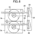
- Fig. 6 illustrates another embodiment of the combined launching device 1 for launching spinning tops according to the present invention.
- the casings 2a, 2a are combined in the transverse direction, and the pinions 12 are engaged with the teeth 21 of different rack belts 20.
- the rack belts 20 be disposed in parallel, and the handles 22 of the two rack belts 20 be integrated into one coupling grip 23. With this structure, the rack belts 20 can be simultaneously operated by pulling the coupling grip 23.
- the projection 3a and the recess 3b are provided as couplers in the above embodiment.
- magnets can be used as couplers.
- one launching unit 2 may have a first suit of a projection and a recess as a coupler and the other launching unit 2 may have a second suit of a projection and a recess as another coupler such that the two launching units 2 are combined with each other by engaging the first suit of a projection and a recess with the second suit of a projection and a recess.
- one launching unit 2 may have a dovetail as a coupler and the other launching unit 2 may have a socket as another coupler such that the two launching units 2 are combined with each other by engaging the dovetail with the socket.
- one launching unit 2 has a semicircular plate as a coupler at the axis and the other launching unit 2 has a semicircular pocket as another coupler such that the two launching units 2 are combined with each other by relatively rotating the two launching units 2 around the axis.
Landscapes
- Toys (AREA)
- Spinning Or Twisting Of Yarns (AREA)
- Motorcycle And Bicycle Frame (AREA)
Claims (4)
- Dispositif de lancement combiné (1) pour lancer des toupies (30, 30), comprenant :une première unité de lancement (2) comprenant un premier boîtier (2a), le premier boîtier (2a) contenant un premier porte-toupie (15) pour tenir une première toupie (30) et un premier mécanisme de rotation (10), dans lequel le premier mécanisme de rotation (10) est actionné pour faire tourner et lancer la première toupie (30) en déplaçant manuellement et dans le plan linéaire un membre d'actionnement (20) dans une direction d'actionnement prédéterminée ; etune deuxième unité de lancement (2) comprenant un deuxième boîtier (2a), le deuxième boîtier (2a) contenant un deuxième porte-toupie (15) pour tenir une deuxième toupie (30 et un deuxième mécanisme de rotation (10), dans lequel le deuxième mécanisme de rotation (10) est actionné pour faire tourner et lancer la deuxième toupie (30) en déplaçant manuellement et dans le plan linéaire un membre d'actionnement (20) dans la direction d'actionnement prédéterminée,caractérisé en ce quele premier boîtier (2a) de la première unité de lancement (2) a un premier coupleur (3a), et le deuxième boîtier (2a) de la deuxième unité de lancement (2) a un deuxième coupleur (3b) combiné d'une manière amovible au premier coupleur (3a), etdans lequel la première unité de lancement (2) est combinée avec la deuxième unité de lancement (2) de telle sorte que le premier et le deuxième porte-toupie (15, 15) font face dans la même direction et la direction d'actionnement prédéterminée du membre d'actionnement (20) est la même pour la première et la deuxième unité de lancement (2, 2).
- Dispositif de lancement combiné (1) pour lancer des toupies (30, 30) selon la revendication 1, dans lequel le membre d'actionnement est une courroie à crémaillère (20).
- Dispositif de lancement combiné (1) pour lancer des toupies (30, 30) selon la revendication 2, dans lequel la première unité de lancement (2) est combinée avec la deuxième unité de lancement (2) de telle sorte que la courroie à crémaillère (20) est engagée tant avec un pignon (12) du premier mécanisme de rotation (10) qu'avec un pignon (12) du deuxième mécanisme de rotation (10).
- Dispositif de lancement combiné (1) pour lancer des toupies (30, 30) selon l'une quelconque des revendications 1 à 3, dans lequel la première unité de lancement (2) a le premier coupleur (3a) et le deuxième coupleur (3b) tous les deux et la deuxième unité de lancement (2) a le premier coupleur (3a) et le deuxième coupleur (3b) tous les deux.
Applications Claiming Priority (1)
| Application Number | Priority Date | Filing Date | Title |
|---|---|---|---|
| JP2015245219A JP5927335B1 (ja) | 2015-12-16 | 2015-12-16 | 連結コマ発射装置 |
Publications (2)
| Publication Number | Publication Date |
|---|---|
| EP3147007A1 EP3147007A1 (fr) | 2017-03-29 |
| EP3147007B1 true EP3147007B1 (fr) | 2018-02-28 |
Family
ID=56089761
Family Applications (1)
| Application Number | Title | Priority Date | Filing Date |
|---|---|---|---|
| EP16170807.8A Not-in-force EP3147007B1 (fr) | 2015-12-16 | 2016-05-23 | Dispositif de lancement combiné pour lancer des toupies |
Country Status (4)
| Country | Link |
|---|---|
| US (2) | US9968860B2 (fr) |
| EP (1) | EP3147007B1 (fr) |
| JP (1) | JP5927335B1 (fr) |
| CN (1) | CN205699411U (fr) |
Families Citing this family (22)
| Publication number | Priority date | Publication date | Assignee | Title |
|---|---|---|---|---|
| JP5927335B1 (ja) * | 2015-12-16 | 2016-06-01 | 株式会社タカラトミー | 連結コマ発射装置 |
| JP1556349S (fr) * | 2016-02-05 | 2016-08-15 | ||
| CN205796499U (zh) * | 2016-07-08 | 2016-12-14 | 广州市三宝玩具有限公司 | 一种陀螺加速装置 |
| JP1570497S (fr) * | 2016-07-15 | 2017-02-27 | ||
| JP1575628S (fr) * | 2016-12-05 | 2017-10-23 | ||
| JP1582206S (fr) * | 2017-01-24 | 2017-07-24 | ||
| JP1582207S (fr) * | 2017-01-24 | 2017-07-24 | ||
| JP1582213S (fr) * | 2017-01-27 | 2017-07-24 | ||
| JP1582435S (fr) * | 2017-01-27 | 2018-01-22 | ||
| JP6240350B1 (ja) * | 2017-02-01 | 2017-11-29 | 株式会社タカラトミー | コマ発射装置 |
| JP1582216S (fr) * | 2017-02-03 | 2017-07-24 | ||
| JP1582939S (fr) * | 2017-02-20 | 2018-01-29 | ||
| US10449465B2 (en) * | 2017-10-27 | 2019-10-22 | John Mathew Hyun | Toy having push lock and drive mechanism |
| KR200487329Y1 (ko) * | 2018-04-09 | 2018-09-04 | 박경선 | 스피너 런쳐 |
| JP6494838B1 (ja) * | 2018-06-01 | 2019-04-03 | 株式会社バンダイ | 動作玩具 |
| WO2020017747A1 (fr) * | 2018-07-17 | 2020-01-23 | 김용철 | Toupie modifiée préfabriquée et lanceur pour lancer une toupie modifiée |
| JP6671663B1 (ja) * | 2018-10-30 | 2020-03-25 | 株式会社タカラトミー | コマ発射装置 |
| CN110279276A (zh) * | 2019-08-13 | 2019-09-27 | 邱怡苹 | 可伸缩的晾衣架 |
| US20230182033A1 (en) * | 2021-12-09 | 2023-06-15 | Moose Creative Management Pty Limited | Toy controller |
| JP7492710B2 (ja) * | 2022-08-23 | 2024-05-30 | 株式会社タカラトミー | コマ発射装置 |
| JP1749751S (ja) * | 2023-03-01 | 2023-07-31 | コマおもちゃ発射器具用巻き上げ器 | |
| JP1762096S (ja) * | 2023-07-25 | 2024-01-23 | コマおもちゃ用発射器具 |
Family Cites Families (35)
| Publication number | Priority date | Publication date | Assignee | Title |
|---|---|---|---|---|
| US1552530A (en) * | 1921-08-11 | 1925-09-08 | Woods George Adams | Game apparatus |
| US1907419A (en) * | 1931-12-18 | 1933-05-02 | Clare A Wetzell | Top |
| US2068053A (en) * | 1936-07-29 | 1937-01-19 | Ernest G Gehman | Multiple spinning top device |
| US2633664A (en) * | 1951-01-05 | 1953-04-07 | Neilson Roger | Quin-top |
| US2966004A (en) * | 1958-10-13 | 1960-12-27 | Joseph A Schustrin | Multiple launcher for toy tops |
| US3246424A (en) * | 1963-04-11 | 1966-04-19 | Joseph E Gregory | Spinning toy launcher |
| US3449859A (en) * | 1967-03-07 | 1969-06-17 | Roger L Neilson | Assemblable multiple top spinning device and apparatus |
| US3594943A (en) * | 1970-06-08 | 1971-07-27 | Mattel Inc | Toy top pivot accessory |
| US3701216A (en) * | 1971-12-22 | 1972-10-31 | California R & D Center | Wheel apparatus and rack and pinion launcher enabling repeated strokes and having automatic ejector |
| US3815911A (en) * | 1972-02-03 | 1974-06-11 | Ideal Toy Corp | Racing tops |
| JPS50120599A (fr) | 1974-03-06 | 1975-09-20 | ||
| JPS50120599U (fr) * | 1974-03-16 | 1975-10-02 | ||
| USD246197S (en) * | 1975-07-24 | 1977-10-25 | Sanyei Corporation | Stylized boxing game apparatus, or similar article |
| US4043556A (en) * | 1976-03-22 | 1977-08-23 | Lappa Cleto L | Wheel rolling game |
| JPH0213595U (fr) * | 1988-03-10 | 1990-01-29 | ||
| JPH0213595A (ja) | 1988-06-28 | 1990-01-17 | Touden Kogyo Kk | 重量物を吊り上げ横転せしめる方法およびローラー付きシャックル吊り金具 |
| US4867728A (en) * | 1988-10-11 | 1989-09-19 | The Quaker Oats Company | Toy top launcher |
| JPH0390580A (ja) | 1989-08-31 | 1991-04-16 | Taiyo Yuden Co Ltd | 霧化薄膜形成方法 |
| US5017172A (en) * | 1990-01-16 | 1991-05-21 | Seifert C Vaughn | Convertible yo-yo and top |
| US5518437A (en) * | 1993-10-12 | 1996-05-21 | Kabushiki Kaisha Bandai | Toy top and drive unit for spinning the top |
| USD353848S (en) * | 1993-10-22 | 1994-12-27 | Tsuyoshi Nonaka | Top spinner |
| US6364734B1 (en) * | 2000-04-14 | 2002-04-02 | Ricky Ng | Toy top structure and system |
| JP3612508B2 (ja) * | 2001-09-28 | 2005-01-19 | 株式会社タカラ | コマ玩具システム |
| JP3090580U (ja) * | 2002-03-14 | 2002-12-20 | 誠 会田 | 2個同時発射型コマ玩具発射装置 |
| JP3532904B2 (ja) * | 2002-05-07 | 2004-05-31 | 株式会社タカラ | ゲーム玩具 |
| US6743070B1 (en) * | 2003-02-26 | 2004-06-01 | Mon-Sheng Lin | Whipping top based bubble toy |
| US20060148373A1 (en) * | 2004-08-25 | 2006-07-06 | Jakks Pacific, Inc. | Integrated carrying case and toy object launcher |
| US20060211331A1 (en) * | 2005-03-16 | 2006-09-21 | Mattel, Inc. | Toy wheel launcher |
| JP3160157U (ja) * | 2010-01-15 | 2010-06-17 | 株式会社タカラトミー | コマ玩具発射装置 |
| JP3164823U (ja) * | 2010-10-06 | 2010-12-16 | 株式会社タカラトミー | コマ玩具発射装置 |
| US8795027B2 (en) * | 2011-08-09 | 2014-08-05 | Boy Scouts Of America | CO2 model car launcher |
| KR101332506B1 (ko) * | 2012-02-20 | 2013-11-26 | 최신규 | 완구용 팽이 |
| US9707488B2 (en) * | 2013-05-03 | 2017-07-18 | Mattel, Inc. | Toy vehicle, launching apparatus therefor and methods of using the same |
| EP3037145B1 (fr) * | 2013-08-22 | 2019-03-13 | Choi, Jong-Ill | Toupie |
| JP5927335B1 (ja) * | 2015-12-16 | 2016-06-01 | 株式会社タカラトミー | 連結コマ発射装置 |
-
2015
- 2015-12-16 JP JP2015245219A patent/JP5927335B1/ja active Active
-
2016
- 2016-02-18 CN CN201620126240.0U patent/CN205699411U/zh not_active Expired - Fee Related
- 2016-05-23 EP EP16170807.8A patent/EP3147007B1/fr not_active Not-in-force
- 2016-05-26 US US15/165,240 patent/US9968860B2/en active Active
-
2018
- 2018-03-09 US US15/916,565 patent/US20180193758A1/en not_active Abandoned
Non-Patent Citations (1)
| Title |
|---|
| None * |
Also Published As
| Publication number | Publication date |
|---|---|
| EP3147007A1 (fr) | 2017-03-29 |
| US20170173477A1 (en) | 2017-06-22 |
| JP5927335B1 (ja) | 2016-06-01 |
| JP2017108896A (ja) | 2017-06-22 |
| CN205699411U (zh) | 2016-11-23 |
| US20180193758A1 (en) | 2018-07-12 |
| US9968860B2 (en) | 2018-05-15 |
Similar Documents
| Publication | Publication Date | Title |
|---|---|---|
| EP3147007B1 (fr) | Dispositif de lancement combiné pour lancer des toupies | |
| CN106029503B (zh) | 限位装置及具有该限位装置的无人飞行器 | |
| CN108036171B (zh) | 云台 | |
| WO2016026318A1 (fr) | Gyroscope jouet combiné pouvant être assemblé librement | |
| CN218944347U (zh) | 陀螺发射装置 | |
| US11035438B2 (en) | Transmission mechanism, follow focus, follow focus actuator, and imaging device | |
| CN104460881A (zh) | 闩锁装置及采用该闩锁装置的服务器 | |
| US9327204B2 (en) | Remote controlled and rechargeable toy helicopter | |
| JP5328107B2 (ja) | 遊技機 | |
| CN104637731A (zh) | 继电器、标志结构及标志组件 | |
| CN105727565A (zh) | 一种自驱动陀螺及基于该自驱动陀螺的子母陀螺 | |
| JP2009148333A (ja) | 基板ケース、並びに、遊技機 | |
| JP2019146664A (ja) | コマ玩具 | |
| WO2021062979A1 (fr) | Jouet d'éjection à roues gauches | |
| BRPI0407137A (pt) | Conexão plug-in removìvel para dutos de alta pressão | |
| US10001339B1 (en) | Toy gun bullet container structure | |
| US3064951A (en) | Electric mixer | |
| JP4394739B1 (ja) | アクセサリ生成玩具 | |
| JP2015170811A (ja) | 電子機器 | |
| JP2008220721A (ja) | スロットマシン | |
| JP5159909B2 (ja) | プラグ付属部品 | |
| CN221579703U (zh) | 一种直立式陀螺发射器 | |
| CN205728056U (zh) | 雾化装置及带有该雾化装置的电子烟 | |
| JP5133792B2 (ja) | 遊技機 | |
| JP5870133B2 (ja) | 遊技機 |
Legal Events
| Date | Code | Title | Description |
|---|---|---|---|
| PUAI | Public reference made under article 153(3) epc to a published international application that has entered the european phase |
Free format text: ORIGINAL CODE: 0009012 |
|
| 17P | Request for examination filed |
Effective date: 20170213 |
|
| AK | Designated contracting states |
Kind code of ref document: A1 Designated state(s): AL AT BE BG CH CY CZ DE DK EE ES FI FR GB GR HR HU IE IS IT LI LT LU LV MC MK MT NL NO PL PT RO RS SE SI SK SM TR |
|
| AX | Request for extension of the european patent |
Extension state: BA ME |
|
| REG | Reference to a national code |
Ref country code: DE Ref legal event code: R079 Ref document number: 602016001709 Country of ref document: DE Free format text: PREVIOUS MAIN CLASS: A63H0001020000 Ipc: A63H0001040000 |
|
| RIC1 | Information provided on ipc code assigned before grant |
Ipc: A63H 1/04 20060101AFI20170626BHEP |
|
| GRAP | Despatch of communication of intention to grant a patent |
Free format text: ORIGINAL CODE: EPIDOSNIGR1 |
|
| INTG | Intention to grant announced |
Effective date: 20170904 |
|
| GRAS | Grant fee paid |
Free format text: ORIGINAL CODE: EPIDOSNIGR3 |
|
| GRAA | (expected) grant |
Free format text: ORIGINAL CODE: 0009210 |
|
| AK | Designated contracting states |
Kind code of ref document: B1 Designated state(s): AL AT BE BG CH CY CZ DE DK EE ES FI FR GB GR HR HU IE IS IT LI LT LU LV MC MK MT NL NO PL PT RO RS SE SI SK SM TR |
|
| REG | Reference to a national code |
Ref country code: GB Ref legal event code: FG4D Ref country code: CH Ref legal event code: EP |
|
| REG | Reference to a national code |
Ref country code: AT Ref legal event code: REF Ref document number: 973503 Country of ref document: AT Kind code of ref document: T Effective date: 20180315 |
|
| REG | Reference to a national code |
Ref country code: IE Ref legal event code: FG4D |
|
| REG | Reference to a national code |
Ref country code: DE Ref legal event code: R096 Ref document number: 602016001709 Country of ref document: DE |
|
| REG | Reference to a national code |
Ref country code: FR Ref legal event code: PLFP Year of fee payment: 3 |
|
| REG | Reference to a national code |
Ref country code: NL Ref legal event code: MP Effective date: 20180228 |
|
| REG | Reference to a national code |
Ref country code: LT Ref legal event code: MG4D |
|
| REG | Reference to a national code |
Ref country code: AT Ref legal event code: MK05 Ref document number: 973503 Country of ref document: AT Kind code of ref document: T Effective date: 20180228 |
|
| PG25 | Lapsed in a contracting state [announced via postgrant information from national office to epo] |
Ref country code: CY Free format text: LAPSE BECAUSE OF FAILURE TO SUBMIT A TRANSLATION OF THE DESCRIPTION OR TO PAY THE FEE WITHIN THE PRESCRIBED TIME-LIMIT Effective date: 20180228 Ref country code: NL Free format text: LAPSE BECAUSE OF FAILURE TO SUBMIT A TRANSLATION OF THE DESCRIPTION OR TO PAY THE FEE WITHIN THE PRESCRIBED TIME-LIMIT Effective date: 20180228 Ref country code: LT Free format text: LAPSE BECAUSE OF FAILURE TO SUBMIT A TRANSLATION OF THE DESCRIPTION OR TO PAY THE FEE WITHIN THE PRESCRIBED TIME-LIMIT Effective date: 20180228 Ref country code: HR Free format text: LAPSE BECAUSE OF FAILURE TO SUBMIT A TRANSLATION OF THE DESCRIPTION OR TO PAY THE FEE WITHIN THE PRESCRIBED TIME-LIMIT Effective date: 20180228 Ref country code: ES Free format text: LAPSE BECAUSE OF FAILURE TO SUBMIT A TRANSLATION OF THE DESCRIPTION OR TO PAY THE FEE WITHIN THE PRESCRIBED TIME-LIMIT Effective date: 20180228 Ref country code: FI Free format text: LAPSE BECAUSE OF FAILURE TO SUBMIT A TRANSLATION OF THE DESCRIPTION OR TO PAY THE FEE WITHIN THE PRESCRIBED TIME-LIMIT Effective date: 20180228 Ref country code: NO Free format text: LAPSE BECAUSE OF FAILURE TO SUBMIT A TRANSLATION OF THE DESCRIPTION OR TO PAY THE FEE WITHIN THE PRESCRIBED TIME-LIMIT Effective date: 20180528 |
|
| PG25 | Lapsed in a contracting state [announced via postgrant information from national office to epo] |
Ref country code: AT Free format text: LAPSE BECAUSE OF FAILURE TO SUBMIT A TRANSLATION OF THE DESCRIPTION OR TO PAY THE FEE WITHIN THE PRESCRIBED TIME-LIMIT Effective date: 20180228 Ref country code: RS Free format text: LAPSE BECAUSE OF FAILURE TO SUBMIT A TRANSLATION OF THE DESCRIPTION OR TO PAY THE FEE WITHIN THE PRESCRIBED TIME-LIMIT Effective date: 20180228 Ref country code: BG Free format text: LAPSE BECAUSE OF FAILURE TO SUBMIT A TRANSLATION OF THE DESCRIPTION OR TO PAY THE FEE WITHIN THE PRESCRIBED TIME-LIMIT Effective date: 20180528 Ref country code: GR Free format text: LAPSE BECAUSE OF FAILURE TO SUBMIT A TRANSLATION OF THE DESCRIPTION OR TO PAY THE FEE WITHIN THE PRESCRIBED TIME-LIMIT Effective date: 20180529 Ref country code: LV Free format text: LAPSE BECAUSE OF FAILURE TO SUBMIT A TRANSLATION OF THE DESCRIPTION OR TO PAY THE FEE WITHIN THE PRESCRIBED TIME-LIMIT Effective date: 20180228 Ref country code: SE Free format text: LAPSE BECAUSE OF FAILURE TO SUBMIT A TRANSLATION OF THE DESCRIPTION OR TO PAY THE FEE WITHIN THE PRESCRIBED TIME-LIMIT Effective date: 20180228 |
|
| PG25 | Lapsed in a contracting state [announced via postgrant information from national office to epo] |
Ref country code: AL Free format text: LAPSE BECAUSE OF FAILURE TO SUBMIT A TRANSLATION OF THE DESCRIPTION OR TO PAY THE FEE WITHIN THE PRESCRIBED TIME-LIMIT Effective date: 20180228 Ref country code: PL Free format text: LAPSE BECAUSE OF FAILURE TO SUBMIT A TRANSLATION OF THE DESCRIPTION OR TO PAY THE FEE WITHIN THE PRESCRIBED TIME-LIMIT Effective date: 20180228 Ref country code: EE Free format text: LAPSE BECAUSE OF FAILURE TO SUBMIT A TRANSLATION OF THE DESCRIPTION OR TO PAY THE FEE WITHIN THE PRESCRIBED TIME-LIMIT Effective date: 20180228 Ref country code: RO Free format text: LAPSE BECAUSE OF FAILURE TO SUBMIT A TRANSLATION OF THE DESCRIPTION OR TO PAY THE FEE WITHIN THE PRESCRIBED TIME-LIMIT Effective date: 20180228 Ref country code: IT Free format text: LAPSE BECAUSE OF FAILURE TO SUBMIT A TRANSLATION OF THE DESCRIPTION OR TO PAY THE FEE WITHIN THE PRESCRIBED TIME-LIMIT Effective date: 20180228 |
|
| REG | Reference to a national code |
Ref country code: DE Ref legal event code: R097 Ref document number: 602016001709 Country of ref document: DE |
|
| PG25 | Lapsed in a contracting state [announced via postgrant information from national office to epo] |
Ref country code: SK Free format text: LAPSE BECAUSE OF FAILURE TO SUBMIT A TRANSLATION OF THE DESCRIPTION OR TO PAY THE FEE WITHIN THE PRESCRIBED TIME-LIMIT Effective date: 20180228 Ref country code: DK Free format text: LAPSE BECAUSE OF FAILURE TO SUBMIT A TRANSLATION OF THE DESCRIPTION OR TO PAY THE FEE WITHIN THE PRESCRIBED TIME-LIMIT Effective date: 20180228 Ref country code: SM Free format text: LAPSE BECAUSE OF FAILURE TO SUBMIT A TRANSLATION OF THE DESCRIPTION OR TO PAY THE FEE WITHIN THE PRESCRIBED TIME-LIMIT Effective date: 20180228 Ref country code: CZ Free format text: LAPSE BECAUSE OF FAILURE TO SUBMIT A TRANSLATION OF THE DESCRIPTION OR TO PAY THE FEE WITHIN THE PRESCRIBED TIME-LIMIT Effective date: 20180228 |
|
| PLBE | No opposition filed within time limit |
Free format text: ORIGINAL CODE: 0009261 |
|
| STAA | Information on the status of an ep patent application or granted ep patent |
Free format text: STATUS: NO OPPOSITION FILED WITHIN TIME LIMIT |
|
| REG | Reference to a national code |
Ref country code: BE Ref legal event code: MM Effective date: 20180531 |
|
| PG25 | Lapsed in a contracting state [announced via postgrant information from national office to epo] |
Ref country code: MC Free format text: LAPSE BECAUSE OF FAILURE TO SUBMIT A TRANSLATION OF THE DESCRIPTION OR TO PAY THE FEE WITHIN THE PRESCRIBED TIME-LIMIT Effective date: 20180228 |
|
| 26N | No opposition filed |
Effective date: 20181129 |
|
| REG | Reference to a national code |
Ref country code: IE Ref legal event code: MM4A |
|
| PG25 | Lapsed in a contracting state [announced via postgrant information from national office to epo] |
Ref country code: SI Free format text: LAPSE BECAUSE OF FAILURE TO SUBMIT A TRANSLATION OF THE DESCRIPTION OR TO PAY THE FEE WITHIN THE PRESCRIBED TIME-LIMIT Effective date: 20180228 |
|
| PG25 | Lapsed in a contracting state [announced via postgrant information from national office to epo] |
Ref country code: LU Free format text: LAPSE BECAUSE OF NON-PAYMENT OF DUE FEES Effective date: 20180523 |
|
| PG25 | Lapsed in a contracting state [announced via postgrant information from national office to epo] |
Ref country code: IE Free format text: LAPSE BECAUSE OF NON-PAYMENT OF DUE FEES Effective date: 20180523 |
|
| PG25 | Lapsed in a contracting state [announced via postgrant information from national office to epo] |
Ref country code: BE Free format text: LAPSE BECAUSE OF NON-PAYMENT OF DUE FEES Effective date: 20180531 |
|
| REG | Reference to a national code |
Ref country code: CH Ref legal event code: PL |
|
| PG25 | Lapsed in a contracting state [announced via postgrant information from national office to epo] |
Ref country code: LI Free format text: LAPSE BECAUSE OF NON-PAYMENT OF DUE FEES Effective date: 20190531 Ref country code: MT Free format text: LAPSE BECAUSE OF NON-PAYMENT OF DUE FEES Effective date: 20180523 Ref country code: CH Free format text: LAPSE BECAUSE OF NON-PAYMENT OF DUE FEES Effective date: 20190531 |
|
| PG25 | Lapsed in a contracting state [announced via postgrant information from national office to epo] |
Ref country code: TR Free format text: LAPSE BECAUSE OF FAILURE TO SUBMIT A TRANSLATION OF THE DESCRIPTION OR TO PAY THE FEE WITHIN THE PRESCRIBED TIME-LIMIT Effective date: 20180228 |
|
| PG25 | Lapsed in a contracting state [announced via postgrant information from national office to epo] |
Ref country code: PT Free format text: LAPSE BECAUSE OF FAILURE TO SUBMIT A TRANSLATION OF THE DESCRIPTION OR TO PAY THE FEE WITHIN THE PRESCRIBED TIME-LIMIT Effective date: 20180228 |
|
| PG25 | Lapsed in a contracting state [announced via postgrant information from national office to epo] |
Ref country code: MK Free format text: LAPSE BECAUSE OF NON-PAYMENT OF DUE FEES Effective date: 20180228 Ref country code: HU Free format text: LAPSE BECAUSE OF FAILURE TO SUBMIT A TRANSLATION OF THE DESCRIPTION OR TO PAY THE FEE WITHIN THE PRESCRIBED TIME-LIMIT; INVALID AB INITIO Effective date: 20160523 |
|
| PG25 | Lapsed in a contracting state [announced via postgrant information from national office to epo] |
Ref country code: IS Free format text: LAPSE BECAUSE OF FAILURE TO SUBMIT A TRANSLATION OF THE DESCRIPTION OR TO PAY THE FEE WITHIN THE PRESCRIBED TIME-LIMIT Effective date: 20180628 |
|
| PGFP | Annual fee paid to national office [announced via postgrant information from national office to epo] |
Ref country code: FR Payment date: 20200522 Year of fee payment: 5 Ref country code: DE Payment date: 20200520 Year of fee payment: 5 |
|
| PGFP | Annual fee paid to national office [announced via postgrant information from national office to epo] |
Ref country code: GB Payment date: 20200527 Year of fee payment: 5 |
|
| REG | Reference to a national code |
Ref country code: DE Ref legal event code: R119 Ref document number: 602016001709 Country of ref document: DE |
|
| GBPC | Gb: european patent ceased through non-payment of renewal fee |
Effective date: 20210523 |
|
| PG25 | Lapsed in a contracting state [announced via postgrant information from national office to epo] |
Ref country code: GB Free format text: LAPSE BECAUSE OF NON-PAYMENT OF DUE FEES Effective date: 20210523 Ref country code: DE Free format text: LAPSE BECAUSE OF NON-PAYMENT OF DUE FEES Effective date: 20211201 |
|
| PG25 | Lapsed in a contracting state [announced via postgrant information from national office to epo] |
Ref country code: FR Free format text: LAPSE BECAUSE OF NON-PAYMENT OF DUE FEES Effective date: 20210531 |