EP3147032B1 - Dispositif de préparation et de distribution de réactif - Google Patents
Dispositif de préparation et de distribution de réactif Download PDFInfo
- Publication number
- EP3147032B1 EP3147032B1 EP16190922.1A EP16190922A EP3147032B1 EP 3147032 B1 EP3147032 B1 EP 3147032B1 EP 16190922 A EP16190922 A EP 16190922A EP 3147032 B1 EP3147032 B1 EP 3147032B1
- Authority
- EP
- European Patent Office
- Prior art keywords
- reagent
- reaction chamber
- barrel
- plunger
- dispensing
- Prior art date
- Legal status (The legal status is an assumption and is not a legal conclusion. Google has not performed a legal analysis and makes no representation as to the accuracy of the status listed.)
- Active
Links
Images







Classifications
-
- B—PERFORMING OPERATIONS; TRANSPORTING
- B01—PHYSICAL OR CHEMICAL PROCESSES OR APPARATUS IN GENERAL
- B01L—CHEMICAL OR PHYSICAL LABORATORY APPARATUS FOR GENERAL USE
- B01L3/00—Containers or dishes for laboratory use, e.g. laboratory glassware; Droppers
- B01L3/02—Burettes; Pipettes
- B01L3/0203—Burettes, i.e. for withdrawing and redistributing liquids through different conduits
- B01L3/0206—Burettes, i.e. for withdrawing and redistributing liquids through different conduits of the plunger pump type
-
- A—HUMAN NECESSITIES
- A61—MEDICAL OR VETERINARY SCIENCE; HYGIENE
- A61M—DEVICES FOR INTRODUCING MEDIA INTO, OR ONTO, THE BODY; DEVICES FOR TRANSDUCING BODY MEDIA OR FOR TAKING MEDIA FROM THE BODY; DEVICES FOR PRODUCING OR ENDING SLEEP OR STUPOR
- A61M5/00—Devices for bringing media into the body in a subcutaneous, intra-vascular or intramuscular way; Accessories therefor, e.g. filling or cleaning devices, arm-rests
- A61M5/178—Syringes
- A61M5/28—Syringe ampoules or carpules, i.e. ampoules or carpules provided with a needle
- A61M5/284—Syringe ampoules or carpules, i.e. ampoules or carpules provided with a needle comprising means for injection of two or more media, e.g. by mixing
-
- A—HUMAN NECESSITIES
- A61—MEDICAL OR VETERINARY SCIENCE; HYGIENE
- A61M—DEVICES FOR INTRODUCING MEDIA INTO, OR ONTO, THE BODY; DEVICES FOR TRANSDUCING BODY MEDIA OR FOR TAKING MEDIA FROM THE BODY; DEVICES FOR PRODUCING OR ENDING SLEEP OR STUPOR
- A61M5/00—Devices for bringing media into the body in a subcutaneous, intra-vascular or intramuscular way; Accessories therefor, e.g. filling or cleaning devices, arm-rests
- A61M5/178—Syringes
- A61M5/31—Details
- A61M5/315—Pistons; Piston-rods; Guiding, blocking or restricting the movement of the rod or piston; Appliances on the rod for facilitating dosing ; Dosing mechanisms
- A61M5/31511—Piston or piston-rod constructions, e.g. connection of piston with piston-rod
-
- B—PERFORMING OPERATIONS; TRANSPORTING
- B01—PHYSICAL OR CHEMICAL PROCESSES OR APPARATUS IN GENERAL
- B01L—CHEMICAL OR PHYSICAL LABORATORY APPARATUS FOR GENERAL USE
- B01L3/00—Containers or dishes for laboratory use, e.g. laboratory glassware; Droppers
- B01L3/52—Containers specially adapted for storing or dispensing a reagent
-
- A—HUMAN NECESSITIES
- A61—MEDICAL OR VETERINARY SCIENCE; HYGIENE
- A61M—DEVICES FOR INTRODUCING MEDIA INTO, OR ONTO, THE BODY; DEVICES FOR TRANSDUCING BODY MEDIA OR FOR TAKING MEDIA FROM THE BODY; DEVICES FOR PRODUCING OR ENDING SLEEP OR STUPOR
- A61M5/00—Devices for bringing media into the body in a subcutaneous, intra-vascular or intramuscular way; Accessories therefor, e.g. filling or cleaning devices, arm-rests
- A61M5/178—Syringes
- A61M2005/1787—Syringes for sequential delivery of fluids, e.g. first medicament and then flushing liquid
-
- A—HUMAN NECESSITIES
- A61—MEDICAL OR VETERINARY SCIENCE; HYGIENE
- A61M—DEVICES FOR INTRODUCING MEDIA INTO, OR ONTO, THE BODY; DEVICES FOR TRANSDUCING BODY MEDIA OR FOR TAKING MEDIA FROM THE BODY; DEVICES FOR PRODUCING OR ENDING SLEEP OR STUPOR
- A61M5/00—Devices for bringing media into the body in a subcutaneous, intra-vascular or intramuscular way; Accessories therefor, e.g. filling or cleaning devices, arm-rests
- A61M5/178—Syringes
- A61M5/31—Details
- A61M2005/3103—Leak prevention means for distal end of syringes, i.e. syringe end for mounting a needle
- A61M2005/3104—Caps for syringes without needle
-
- A—HUMAN NECESSITIES
- A61—MEDICAL OR VETERINARY SCIENCE; HYGIENE
- A61M—DEVICES FOR INTRODUCING MEDIA INTO, OR ONTO, THE BODY; DEVICES FOR TRANSDUCING BODY MEDIA OR FOR TAKING MEDIA FROM THE BODY; DEVICES FOR PRODUCING OR ENDING SLEEP OR STUPOR
- A61M5/00—Devices for bringing media into the body in a subcutaneous, intra-vascular or intramuscular way; Accessories therefor, e.g. filling or cleaning devices, arm-rests
- A61M5/178—Syringes
- A61M5/31—Details
- A61M2005/3117—Means preventing contamination of the medicament compartment of a syringe
- A61M2005/3118—Means preventing contamination of the medicament compartment of a syringe via the distal end of a syringe, i.e. syringe end for mounting a needle cannula
- A61M2005/312—Means preventing contamination of the medicament compartment of a syringe via the distal end of a syringe, i.e. syringe end for mounting a needle cannula comprising sealing means, e.g. severable caps, to be removed prior to injection by, e.g. tearing or twisting
-
- A—HUMAN NECESSITIES
- A61—MEDICAL OR VETERINARY SCIENCE; HYGIENE
- A61M—DEVICES FOR INTRODUCING MEDIA INTO, OR ONTO, THE BODY; DEVICES FOR TRANSDUCING BODY MEDIA OR FOR TAKING MEDIA FROM THE BODY; DEVICES FOR PRODUCING OR ENDING SLEEP OR STUPOR
- A61M5/00—Devices for bringing media into the body in a subcutaneous, intra-vascular or intramuscular way; Accessories therefor, e.g. filling or cleaning devices, arm-rests
- A61M5/178—Syringes
- A61M5/31—Details
- A61M2005/3123—Details having air entrapping or venting means, e.g. purging channels in pistons
-
- A—HUMAN NECESSITIES
- A61—MEDICAL OR VETERINARY SCIENCE; HYGIENE
- A61M—DEVICES FOR INTRODUCING MEDIA INTO, OR ONTO, THE BODY; DEVICES FOR TRANSDUCING BODY MEDIA OR FOR TAKING MEDIA FROM THE BODY; DEVICES FOR PRODUCING OR ENDING SLEEP OR STUPOR
- A61M5/00—Devices for bringing media into the body in a subcutaneous, intra-vascular or intramuscular way; Accessories therefor, e.g. filling or cleaning devices, arm-rests
- A61M5/178—Syringes
- A61M5/28—Syringe ampoules or carpules, i.e. ampoules or carpules provided with a needle
- A61M5/285—Syringe ampoules or carpules, i.e. ampoules or carpules provided with a needle with sealing means to be broken or opened
Definitions
- the reagent reservoir 210 sized and shaped to retain the reagent 204.
- the reagent 204 includes but is not limited to a freeze-dried or lyophilized reagent capable of rapid reconstitution when introduced to a liquid, such as solution 212.
- the reagent reservoir 210 includes a reaction chamber 208 as shown in Figures 2A and 2B .
- the reaction chamber 208 is sized and shaped to receive the reagent 204 therein.
- the barrel 104 is advanced into the reagent reservoir 210 and the solution and the reagent 204 are reconstituted within the reaction chamber 208 as opposed to the entire reagent reservoir 210.
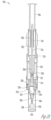
- the activator 106 and the first plunger 200 are shown in a starting position where the first plunger 200 and the first plunger gasket 220 are positioned at one end of the solution reservoir 214 and the solution 212 is retained within the reservoir.
- the activator 106, second plunger 202 and first plunger 200 along with the solution reservoir 214 are translated into the dispensing tip 206 (e.g., the reagent reservoir 210).
- the activator 106 and first plunger 200 are held statically relative to the body 104 and the solution 212 is not forced out of the solution reservoir 214.
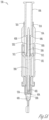
- the plunger 200 remains in the starting position shown in Figure 2A while the barrel 104 is advanced into the reagent reservoir 210 and the reservoir seal 226 shown in Figure 2B is penetrated.
- one or more barrel passages extend through the barrel allowing the gas displaced from the reaction chamber 208 to vent from the reagent preparation and dispensing device 100 during addition of the solution 212 to the reaction chamber.
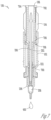
- Figures 4A and 4B show two views of the reagent preparation and dispensing device 100. The view in 4B is rotated relative to the view in 4A and both views include barrel passages 412. By providing a plurality of barrel passages 412 through the barrel 104 gas displaced by the addition of the solution 212 to the reaction chamber 208 is easily able to pass through the barrel 104 and continue along the vent path 408.
- the vent path 408 remains open throughout the entire movement of the first plunger 200 relative to the barrel 104.
- the vent path 408 is substantially isolated from the solution reservoir 214 and the reaction chamber 208 and only in communication with the reaction chamber 208 through the reaction chamber vents 410.
- the first plunger 200 is thereby able to freely translate from the position in Figure 3B to the seated position shown in Figure 4B thereby moving the entirety of the solution 212 into the reaction chamber 208 while venting displaced gas through the vent path 408.
- the flushing fluid chamber 600 includes a sufficient amount of flushing gas (or another fluid configured for flushing the reagent mixture 400) through the dimensioning of the volume of the chamber to enable the full dispensing of the reagent mixture 400 through the depression of the activator 106 and corresponding movement of flushing fluid through the flushing passage 602 into the reaction chamber 208.
- the flushing fluid chamber 600 has a volume greater than the volume of the reaction chamber 208.
- the barrel 104, the activator 106 and the second plunger 202 are sized and shaped to ensure that full movement of the activator 106 and second plunger 202 into the barrel 104 fully pushes the volume of flushing fluid within the flushing fluid chamber 600 into the reaction chamber 208.
- the technician After engagement of the second plunger gasket 222, the first activator flange 704 and the second activator flange 706 with corresponding stops and seats 700, 702, 708 the technician is affirmatively aware the reagent mixture 400 is fully dispensed from the reagent preparation and dispensing device 100 because the activator 106 is fully engaged and further movement of the activator 106 into the device 100 is substantially prevented.
- tactile sensation e.g., arresting of further movement, the technician is confident that the full amount of the reagent mixture 400 is dispensed from the reagent preparation and dispensing device.
- the cap 108 includes, in one example, a desiccant 216 that cooperates with the frangible tip 238 to substantially prevent the ingress of moisture into the reagent reservoir 210. Undesired reconstitution of the reagent 204 prior to piercing of the reservoir seal 226 is thereby prevented.
- a flushing fluid chamber 600 is formed.
- the flushing fluid chamber 600 is formed by the second plunger 202 engaged with the barrel inner wall 604.
- the flushing fluid chamber 600 communicates with the reaction chamber 208 through the flushing path 602.
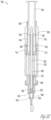
- the flushing path 602 travels through the reagent preparation and dispensing device 100 in a similar manner to the vent path 408 shown in Figure 5B .
- the flushing path 602 extends through the barrel passages 412 along the barrel 104 between the interconnecting gasket 228.
- an activator 106 is movably coupled with the body 102.
- the activator 106 is movable to force the solution 212 into the reaction chamber 208 and form a reagent mixture, such as the reagent mixture 400 shown in Figure 4A .
- the activator 106 is selectively coupled with a first plunger 200. Movement of the activator 106 is transmitted to the first plunger 200 to force the solution 212 into the reaction chamber 208.
- lugs and stops on one or more of the activator 106 and the first plunger 200 facilitate selective engagement between the activator and the first plunger 200.
- the vent path 408 continues to extend through the barrel 104 along the barrel inner wall (e.g., vent wall) past activator lugs 308 and out of the barrel 104.
- a first portion of the vent path 408 includes the portion of the vent path extending from the reaction chamber 208 along an exterior of the barrel 104 to the barrel passages 412.
- a second portion of the vent path 408 extends through the interior of the barrel 104 between the inner barrel wall 604 and the first plunger 200.
- the second portion of the vent path 408 continues through the interior of the barrel 408 along the barrel inner wall 604 and the second plunger 202 and activator 106.
- the method 900 includes movably coupling a second plunger 202 with the body 104 (e.g., the barrel 104) and the second plunger is operable to close the vent path 408 and push the flushing fluid from the flushing chamber 600 through the vent path 408 (e.g., the flushing path 602) into the reaction chamber 208.
- the vent path 408 e.g., the flushing path 602
- the second plunger 202 moves relative to the body 102 and the barrel 104 seals the vent path 408.
- the reagent preparation and dispensing device 100 thereby uses the features and elements defining the vent path 408 for dispensing of the reagent mixture 400 from the dispensing tip 206.
- reconstituting of the reagent 204 is conducted adjacent to the dispensing tip 206 in a first portion of the reaction chamber 208.
- the reaction chamber gases are vented from a second portion of the reaction chamber remote from the first portion of the reaction chamber. That is to say, the reconstitution of the reagent 208 is conducted at a bottom portion of the reaction chamber 208 and the venting of the displaced reaction chamber gases begins at a second portion of the reaction chamber opposed to the bottom portion of the reaction chamber.
- the reagent preparation and dispensing device includes one or more vent paths extending from the reaction chamber containing the reagent and containing the reagent mixture after addition of the solution to the reagent.
- the vent path vents gases from the reaction chamber displaced by the addition of the solution and substantially prevents the development of overpressure within the reaction chamber during reconstitution.
- the technician is able to easily reconstitute the reagent through the addition of the solution without resistance to movement of the activator through back pressure developed within the reaction chamber.
- venting reaction chamber gases from the reaction chamber over pressure developed within the reaction chamber is thereby avoided to substantially prevent the risk of premature opening of a dispensing tip or the braking of a seal of the reaction chamber.
- the reagent is thereby fully reconstituted prior to dispensing of the reagent from the device.
Landscapes
- Health & Medical Sciences (AREA)
- Animal Behavior & Ethology (AREA)
- Veterinary Medicine (AREA)
- Anesthesiology (AREA)
- Biomedical Technology (AREA)
- Heart & Thoracic Surgery (AREA)
- Hematology (AREA)
- Life Sciences & Earth Sciences (AREA)
- Vascular Medicine (AREA)
- Engineering & Computer Science (AREA)
- General Health & Medical Sciences (AREA)
- Public Health (AREA)
- Chemical & Material Sciences (AREA)
- Clinical Laboratory Science (AREA)
- Chemical Kinetics & Catalysis (AREA)
- Medicinal Chemistry (AREA)
- Sampling And Sample Adjustment (AREA)
- Automatic Analysis And Handling Materials Therefor (AREA)
- Feeding, Discharge, Calcimining, Fusing, And Gas-Generation Devices (AREA)
Claims (15)
- Appareil, comprenant :un corps (102) incluant :une chambre de réaction (208) configurée pour inclure un réactif, etun réservoir de solution (214) configurée pour inclure une solution ;un piston plongeur (200) couplé de manière mobile avec le corps (102) entre une position de démarrage et une position assise, dans lequel :lorsque le piston plongeur (200) est dans la position de démarrage, le réservoir de solution (214) est isolé de la chambre de réaction (208), etdans lequel le déplacement du piston plongeur (200) de la position de démarrage vers la position assise pousse la solution dans la chambre de réaction (208) ;un trajet de distribution s'étendant depuis la chambre de réaction (208) et jusqu'à l'extérieur du corps (102), dans lequel :dans une première configuration de l'appareil, le trajet de distribution est scellé, etdans une configuration de distribution de l'appareil, le trajet de distribution est configuré pour délivrer un mélange de réactifs formé à partir de la solution et du réactif ;un moyen de rinçage comprenant une chambre de rinçage (600), différente de la chambre de réaction (208), incluant un fluide de rinçage en communication avec la chambre de réaction (208), dans lequel le moyen de rinçage est configuré pour forcer du fluide de rinçage dans la chambre de réaction (208) pour pousser une quantité spécifiée du mélange de réactifs à travers le trajet de distribution ;caractérisé parun trajet d'évacuation (408) s'étendant depuis la chambre de réaction (208) à travers la chambre de rinçage (600), le trajet d'évacuation (408) incluant des configurations ouverte et fermée, dans lequel :dans la configuration ouverte, le trajet d'évacuation (408) s'étend à l'extérieur du corps (102), et le trajet d'évacuation (408) évacue du gaz de la chambre de réaction déplacé par l'addition de la solution dans la chambre de réaction (208), etdans la configuration fermée, une partie du trajet d'évacuation est scellée par rapport à l'extérieur du corps (102), et du fluide de rinçage délivré à partir de la chambre de rinçage (600) à travers la partie du trajet d'évacuation et dans la chambre de réaction (208) distribue le mélange de réactifs à travers le trajet de distribution.
- Appareil selon la revendication 1, dans lequel le piston plongeur (200) est un premier piston plongeur (200), et dans lequel l'appareil comprend en outre :un cylindre (104) couplé de manière mobile au corps (102), le premier piston plongeur (200) étant couplé de manière mobile avec le cylindre (104) ; etun activateur (106), dans lequel, lorsqu'il fonctionne, l'appareil est actionné par le mouvement de l'activateur (106) et d'un ou plusieurs pistons plongeurs comprenant le premier piston plongeur (200), dans lequel, en engageant sélectivement l'activateur (106) avec un ou plusieurs des un ou plusieurs pistons plongeurs, le corps (102) et le cylindre (104), l'opération par étapes du processus de la reconstitution des réactifs et de la distribution du mélange de réactifs est réalisée.
- Appareil selon la revendication 1, comprenant en outre :un cylindre (104) couplé de manière mobile au corps (102), le piston plongeur (200) étant couplé de manière mobile avec le cylindre (104) ; etun réservoir de réactifs comprenant la chambre de réaction (208), dans lequel, dans la première configuration de l'appareil, le cylindre (104) est dans une première position, le réservoir de solution (214) est isolé du réservoir de réactifs et le réservoir de réactifs a un premier volume ;dans une configuration intermédiaire de l'appareil, le cylindre (104) est déplacé en translation par rapport au corps (102) à partir de la première position, le réservoir de solution est en communication avec le réservoir de réactif, et le réservoir de réactif a un deuxième volume plus petit que le premier volume.
- Appareil selon la revendication 3, dans lequel, dans la configuration intermédiaire, le cylindre (104) est assis à l'intérieur du réservoir de réactifs.
- Appareil selon la revendication 1, dans lequel le volume de la chambre de rinçage (600) est supérieur au volume de la chambre de réaction (208).
- Procédé ex vivo de préparation et de distribution de réactifs comprenant :l'ouverture d'une chambre de réaction scellée (208) à un réservoir de solution (214) à l'intérieur d'un corps (102), la chambre de réaction (208) contenant un réactif ;la reconstitution du réactif avec une solution retenue à l'intérieur du réservoir de solution (214) pour former un mélange de réactifs, la reconstitution incluant l'ajout de la solution à la chambre de réaction (208) ; caractérisé parl'évacuation de gaz déplacé de la chambre de réaction (208), le gaz étant déplacé par l'ajout de la solution, le gaz évacué passant par un trajet d'évacuation (408) s'étendant à travers le corps (102), en s'éloignant d'un embout de distribution (206), jusqu'à l'extérieur du corps (102) ; etla distribution d'une quantité spécifiée du mélange de réactifs, la distribution incluant :le fait de sceller une partie du trajet d'évacuation (408) depuis l'extérieur du corps (102) ; etle fait de pousser un fluide de rinçage, à travers la partie du trajet d'évacuation (408), dans la chambre de réaction (208), etdans lequel la reconstitution et la distribution de la quantité spécifiée du mélange de réactifs sont réalisées avec le corps sensiblement dans la même orientation.
- Procédé selon la revendication 6, dans lequel l'évacuation de gaz déplacé inclut la prévention d'une pressurisation à l'intérieur de la chambre de réaction (208) pendant la reconstitution.
- Procédé selon la revendication 6, dans lequel la distribution de la quantité spécifiée du mélange de réactifs inclut la pressurisation de la chambre de réaction (208).
- Procédé selon la revendication 6, dans lequel l'évacuation de gaz déplacé inclut l'évacuation de gaz à travers le corps dans une direction opposée à une direction de distribution de la quantité spécifiée du mélange de réactifs.
- Procédé selon la revendication 6, dans lequel la reconstitution du réactif est adjacente à l'embout de distribution (206) dans une première partie de la chambre de réaction (208), et le gaz est évacué d'une deuxième partie de la chambre de réaction (208) éloignée de la première partie.
- Procédé selon la revendication 6, dans lequel la distribution de la quantité spécifiée du mélange de réactifs inclut le déplacement d'un piston plongeur (202) par rapport au corps (102), et le fait de sceller la partie du trajet d'évacuation depuis l'extérieur du corps inclut la mise en prise du piston plongeur (202) avec une paroi d'évacuation pour sceller une chambre de rinçage (600) formée par le piston plongeur (202) et la paroi d'évacuation, et la poussée du fluide de rinçage à travers la partie du trajet d'évacuation inclut le déplacement du piston plongeur (202) à travers la chambre de rinçage (600).
- Procédé selon la revendication 6, dans lequel l'orientation du corps (102) inclut le fait que l'embout de distribution (206) soit dans une direction descendante.
- Procédé selon la revendication 6, dans lequel la poussée d'un fluide de rinçage à travers la partie du trajet d'évacuation dans la chambre de réaction (208) comprend la poussée d'un fluide de rinçage à partir d'une chambre de rinçage (600) à travers un trajet de rinçage (602) vers la chambre de réaction (208) distribuant le mélange de réactifs de la chambre de réaction (208) à travers le trajet de distribution.
- Procédé selon la revendication 13, dans lequel le volume de la chambre de rinçage est supérieur au volume de la chambre de réaction (208).
- Procédé selon la revendication 6, comprenant en outre le déplacement en translation d'un cylindre (104) par rapport au corps (102), dans lequel :dans une première configuration de l'appareil, le cylindre (104) est dans une première position, le réservoir de solution (214) est isolé d'un réservoir de réactifs incluant la chambre de réaction (208) et le réservoir de réactifs présente un premier volume ;dans une configuration intermédiaire de l'appareil, le cylindre (104) est déplacé en translation par rapport au corps (102) à partir de la première position, le réservoir de solution (214) est en communication avec le réservoir de réactif, et le réservoir de réactif présente un deuxième volume plus petit que le premier volume.
Priority Applications (3)
| Application Number | Priority Date | Filing Date | Title |
|---|---|---|---|
| ES16190922T ES2985610T3 (es) | 2010-11-18 | 2010-11-18 | Dispositivo de preparación y dispensación de reactivo |
| DK16190922.1T DK3147032T3 (da) | 2010-11-18 | 2010-11-18 | Anordning til reagensfremstilling og -distribution |
| EP16190922.1A EP3147032B1 (fr) | 2010-11-18 | 2010-11-18 | Dispositif de préparation et de distribution de réactif |
Applications Claiming Priority (3)
| Application Number | Priority Date | Filing Date | Title |
|---|---|---|---|
| EP10859869.9A EP2640526B1 (fr) | 2010-11-18 | 2010-11-18 | Préparation de réactif et dispositif de distribution |
| EP16190922.1A EP3147032B1 (fr) | 2010-11-18 | 2010-11-18 | Dispositif de préparation et de distribution de réactif |
| PCT/US2010/057238 WO2012067619A1 (fr) | 2010-11-18 | 2010-11-18 | Préparation de réactif et dispositif de distribution |
Related Parent Applications (1)
| Application Number | Title | Priority Date | Filing Date |
|---|---|---|---|
| EP10859869.9A Division EP2640526B1 (fr) | 2010-11-18 | 2010-11-18 | Préparation de réactif et dispositif de distribution |
Publications (2)
| Publication Number | Publication Date |
|---|---|
| EP3147032A1 EP3147032A1 (fr) | 2017-03-29 |
| EP3147032B1 true EP3147032B1 (fr) | 2024-06-12 |
Family
ID=46084315
Family Applications (2)
| Application Number | Title | Priority Date | Filing Date |
|---|---|---|---|
| EP16190922.1A Active EP3147032B1 (fr) | 2010-11-18 | 2010-11-18 | Dispositif de préparation et de distribution de réactif |
| EP10859869.9A Active EP2640526B1 (fr) | 2010-11-18 | 2010-11-18 | Préparation de réactif et dispositif de distribution |
Family Applications After (1)
| Application Number | Title | Priority Date | Filing Date |
|---|---|---|---|
| EP10859869.9A Active EP2640526B1 (fr) | 2010-11-18 | 2010-11-18 | Préparation de réactif et dispositif de distribution |
Country Status (7)
| Country | Link |
|---|---|
| US (2) | US8919390B2 (fr) |
| EP (2) | EP3147032B1 (fr) |
| AU (1) | AU2010363976B2 (fr) |
| CA (2) | CA2817038C (fr) |
| DK (2) | DK3147032T3 (fr) |
| ES (2) | ES2985610T3 (fr) |
| WO (1) | WO2012067619A1 (fr) |
Families Citing this family (16)
| Publication number | Priority date | Publication date | Assignee | Title |
|---|---|---|---|---|
| US8940539B2 (en) * | 2008-05-14 | 2015-01-27 | Biolyph, L.L.C. | Reagent preparation and dispensing device and methods for the same |
| CA2803375C (fr) | 2010-06-29 | 2016-05-10 | Biolyph, Llc | Ensemble de preparation de reactif |
| CA2817038C (fr) | 2010-11-18 | 2015-04-28 | Biolyph, Llc | Preparation de reactif et dispositif de distribution |
| WO2014058615A2 (fr) * | 2012-10-09 | 2014-04-17 | Waters Technologies Corporation | Appareil et procédé d'extraction d'analyte |
| US9895289B2 (en) | 2014-04-18 | 2018-02-20 | Covidien Lp | Mixing syringe |
| US9861752B2 (en) * | 2014-04-18 | 2018-01-09 | Covidien Lp | Mixing nozzle |
| ES2736031T3 (es) * | 2015-04-07 | 2019-12-23 | Hoffmann La Roche | Sistema de gestión de reactivos |
| US10369572B2 (en) | 2015-07-31 | 2019-08-06 | Point Of Care Diagnostics, Llc | Reagent dispensing apparatus |
| AU2017248237B2 (en) * | 2016-04-08 | 2021-10-28 | Hollister Incorporated | Fecal collection device, system and method |
| WO2019156828A1 (fr) * | 2018-02-06 | 2019-08-15 | Siemens Healthcare Diagnostics Inc. | Appareil et procédés prédictifs de contrôle d'inventaire |
| CN110215943A (zh) * | 2019-06-04 | 2019-09-10 | 深圳市贝优通新能源技术开发有限公司 | 一种用于检测黄曲霉毒素的稳定性高的吸取装置 |
| GB202003403D0 (en) * | 2020-03-09 | 2020-04-22 | Oribiotech Ltd | A system for cell processing |
| MX2023003602A (es) * | 2020-09-30 | 2023-04-05 | Univ Leland Stanford Junior | Kit de diagnostico molecular domestico basado en embolo coaxial. |
| EP4244785A4 (fr) | 2020-11-13 | 2024-05-08 | Siemens Healthcare Diagnostics, Inc. | Systèmes et procédés de planification de chargement efficace en matière de calcul de laboratoires de diagnostic |
| US11938092B1 (en) * | 2022-11-30 | 2024-03-26 | D&D Biopharmaceuticals, Inc. | Devices and methods for cornea treatment |
| WO2025137362A1 (fr) * | 2023-12-21 | 2025-06-26 | Abbott Laboratories | Récipients de réactif de distribution et procédés de distribution |
Family Cites Families (91)
| Publication number | Priority date | Publication date | Assignee | Title |
|---|---|---|---|---|
| US2176041A (en) | 1936-06-25 | 1939-10-10 | Sharp & Dohme Inc 1929 | Container for lyophilic biologically active substances |
| US2591706A (en) | 1950-09-29 | 1952-04-08 | Compule Corp | Plural-compartment admixing hypodermic syringe ampoule for segregated storage of ingredients of liquid medicinal solutions and therapeutic preparations |
| US3834387A (en) * | 1972-08-10 | 1974-09-10 | Sherwood Medical Ind Inc | Breech loaded syringe with deformable piston |
| US3946732A (en) * | 1973-08-08 | 1976-03-30 | Ampoules, Inc. | Two-chamber mixing syringe |
| US4226236A (en) * | 1979-05-07 | 1980-10-07 | Abbott Laboratories | Prefilled, vented two-compartment syringe |
| US4516967A (en) | 1981-12-21 | 1985-05-14 | Kopfer Rudolph J | Wet-dry compartmental syringe |
| US4515753A (en) | 1982-11-15 | 1985-05-07 | Technicon Instruments Corporation | Integral reagent dispenser |
| SE458643B (sv) | 1984-12-07 | 1989-04-17 | Pharmacia Ab | Anordning med kolonnelement uppdelat i provparti och referenspatri |
| US5000922A (en) | 1986-02-19 | 1991-03-19 | Jon Turpen | Sample filtration, separation and dispensing device |
| US4693706A (en) | 1986-08-11 | 1987-09-15 | Mark L. Anderson | Two compartment mixing syringe |
| US5114421A (en) | 1986-09-22 | 1992-05-19 | Polak Robert B | Medicament container/dispenser assembly |
| US5071769A (en) | 1986-12-22 | 1991-12-10 | Abbott Laboratories | Method and device for ketone measurement |
| US4768568A (en) * | 1987-07-07 | 1988-09-06 | Survival Technology, Inc. | Hazardous material vial apparatus providing expansible sealed and filter vented chambers |
| US4973168A (en) | 1989-01-13 | 1990-11-27 | Chan Kwan Ho | Vacuum mixing/bone cement cartridge and kit |
| IE66526B1 (en) | 1989-03-17 | 1996-01-24 | Baxter Int | A pre-slit injection site usable with a blunt cannula |
| DK288590D0 (da) | 1990-12-04 | 1990-12-04 | Michael Morris | Blandings/oploesnings-sproejte til cytostatika for medicinsk behandling af cancer patienter |
| US5199949A (en) | 1991-03-08 | 1993-04-06 | Habley Medical Technology Corp. | Multiple pharmaceutical syringe |
| GB9114265D0 (en) | 1991-07-02 | 1991-08-21 | Amersham Int Plc | Sampling device |
| US5232664A (en) | 1991-09-18 | 1993-08-03 | Ventana Medical Systems, Inc. | Liquid dispenser |
| US5242660A (en) | 1992-02-28 | 1993-09-07 | Paul Hsei | Sample preparation device |
| AU665067B2 (en) | 1992-04-30 | 1995-12-14 | Takeda Pharmaceutical Company Limited | Prefilled syringe |
| US5281198A (en) | 1992-05-04 | 1994-01-25 | Habley Medical Technology Corporation | Pharmaceutical component-mixing delivery assembly |
| ES2158886T3 (es) | 1992-12-01 | 2001-09-16 | Tetsuro Higashikawa | Jeringuilla. |
| CA2170160C (fr) | 1993-09-07 | 2002-08-27 | Frederic Neftel | Dispositif de seringue pour le melange de deux composes |
| SK3296A3 (en) * | 1993-12-28 | 1996-05-08 | Tetsuro Higashikawa | The syringe |
| US5637087A (en) | 1995-03-22 | 1997-06-10 | Abbott Laboratories | Prefilled, two-constituent syringe |
| US5785682A (en) | 1995-03-22 | 1998-07-28 | Abbott Laboratories | Pre-filled syringe drug delivery system |
| US5779668A (en) * | 1995-03-29 | 1998-07-14 | Abbott Laboratories | Syringe barrel for lyophilization, reconstitution and administration |
| EP0861330B1 (fr) | 1995-07-12 | 2003-08-20 | Charm Sciences Inc. | Testeur, systeme et procede pour la detection d'echantillons a tester |
| DE19543240A1 (de) | 1995-11-20 | 1997-05-22 | Abion Ohg | Einwegauftragsvorrichtung sowie Kit |
| US5865798A (en) | 1996-06-28 | 1999-02-02 | Becton Dickinson France, S.A. | Stopper assembly having bypass features for use in a multi-chamber syringe barrel |
| AU724089B2 (en) | 1996-12-05 | 2000-09-14 | Idego Aps | Sensor laminates and multi-sectioned fluid delivery devices for detecting by immunoassay target molecules in biological fluids |
| US6045755A (en) | 1997-03-10 | 2000-04-04 | Trega Biosciences,, Inc. | Apparatus and method for combinatorial chemistry synthesis |
| US5879635A (en) | 1997-03-31 | 1999-03-09 | Nason; Frederic L. | Reagent dispenser and related test kit for biological specimens |
| US5971953A (en) * | 1998-01-09 | 1999-10-26 | Bachynsky; Nicholas | Dual chamber syringe apparatus |
| ATE216637T1 (de) | 1997-11-19 | 2002-05-15 | Biognosis Gmbh | Vorrichtung zur sequentiellen ausgabe von fliessfähigen reagenzien |
| US5951160A (en) | 1997-11-20 | 1999-09-14 | Biomet, Inc. | Method and apparatus for packaging, mixing and delivering bone cement |
| US6248294B1 (en) | 1998-04-15 | 2001-06-19 | Frederic L. Nason | Self contained diagnostic test unit |
| US5869003A (en) | 1998-04-15 | 1999-02-09 | Nason; Frederic L. | Self contained diagnostic test unit |
| WO2000009016A1 (fr) | 1998-08-14 | 2000-02-24 | Biocontrol Systems, Inc. | Detection de contaminants au moyen de dispositifs autonomes utilisant des colorants liant les substances cibles |
| DE19847968A1 (de) | 1998-10-17 | 2000-04-20 | Boehringer Ingelheim Pharma | Verschlußkappe und Behälter als Zweikammer-Kartusche für Vernebler zur Erzeugung von Aerosolen |
| DE19912322A1 (de) | 1999-03-19 | 2000-09-28 | Vetter & Co Apotheker | Spritze für medizinische Zwecke |
| US6284549B1 (en) | 1999-05-26 | 2001-09-04 | Ventrex, Inc. | Reagent tube venting system and method |
| FR2799654B1 (fr) | 1999-10-13 | 2002-01-11 | Sod Conseils Rech Applic | Dispositif pour reconstituer une solution, une suspension ou une dispersion therapeutique et procede de preparation et de conditionnement dans ce dispositif |
| EP1103304A3 (fr) | 1999-11-29 | 2003-06-25 | Becton, Dickinson and Company | Récipient pour réactifs autoventilé et méthode pour introduire un réactif dans un analyseur ou un autre appareil |
| CA2396016A1 (fr) | 1999-12-29 | 2001-07-05 | Andy Bernhardt | Systeme servant a reconstituer des pates et procedes d'utilisation |
| US6406175B1 (en) | 2000-05-04 | 2002-06-18 | James F. Marino | Bone cement isovolumic mixing and injection device |
| EP1289659B1 (fr) | 2000-06-02 | 2005-01-26 | BioControl Systems, Inc. | Dispositifs autonomes de detection de contaminants biologiques |
| DE60123237T2 (de) | 2000-06-08 | 2007-09-20 | Meridian Medical Technologies, Inc. | Automatische injektionsvorrichtung mit trockner und flüssiger komponente |
| US6632681B1 (en) | 2000-07-24 | 2003-10-14 | Ey Laboratories | Reagent delivery device and method of use |
| US6953445B2 (en) | 2000-10-10 | 2005-10-11 | Meridian Medical Technologies, Inc. | Wet/dry automatic injector assembly |
| US6656150B2 (en) | 2000-10-10 | 2003-12-02 | Meridian Medical Technologies, Inc. | Wet/dry automatic injector assembly |
| US7556614B2 (en) | 2000-10-10 | 2009-07-07 | Meridian Medical Technologies, Inc. | Separation assembly for drug delivery device |
| US6770052B2 (en) | 2000-10-10 | 2004-08-03 | Meridian Medical Technologies, Inc. | Wet/dry automatic injector assembly |
| US6641561B1 (en) | 2000-10-10 | 2003-11-04 | Meridian Medical Technologies, Inc. | Drug delivery device |
| US7621887B2 (en) | 2000-10-10 | 2009-11-24 | Meridian Medical Technologies, Inc. | Wet/dry automatic injector assembly |
| US20020197631A1 (en) | 2001-04-26 | 2002-12-26 | Lawrence Nathan P. | Multichamber device and uses thereof for processing of biological samples |
| JP2004525379A (ja) | 2001-05-04 | 2004-08-19 | プリスメディカル コーポレーション | 受動撹拌機能付デュアルチャンバ分解容器 |
| DE10140704A1 (de) | 2001-08-18 | 2003-03-06 | Vetter & Co Apotheker | Verfahren zur Durchmischung einer schwer löslichen pharmazeutischen Substanz mit einem Lösungsmittel und Spritze zur Anwendung des Verfahrens |
| JP4112851B2 (ja) | 2001-11-27 | 2008-07-02 | テルモ株式会社 | 2室型プレフィルドシリンジ |
| US20030181826A1 (en) | 2001-12-04 | 2003-09-25 | Dave Smith | Hydrophobic/hydrophilic sample collection tip |
| BRPI0214680B1 (pt) | 2001-12-06 | 2018-09-18 | Biocontrol Systems, Inc. | instrumento para uso em monitorar um produto, um ingrediente, um ambiente ou processo, instrumento para detectar emissão de luz de uma amostra e método de monitorar uma amostra de um produto, um ingrediente, um processo ou ambiente |
| US6820506B2 (en) * | 2002-03-27 | 2004-11-23 | 3M Innovative Properties Company | Multi-chambered pump-valve device |
| US20030209653A1 (en) | 2002-04-24 | 2003-11-13 | Biocontrol Systems, Inc. | Sample collection and testing system |
| US20040170533A1 (en) | 2003-02-27 | 2004-09-02 | Yu-Hui Chu | Syringe for medical tests |
| US7947450B2 (en) | 2003-07-10 | 2011-05-24 | Universite Libre De Bruxelles | Device, kit and method for pulsing biological samples with an agent and stabilising the sample so pulsed |
| KR100519247B1 (ko) | 2003-10-07 | 2005-10-06 | 에이스메디칼 주식회사 | 납작한 원형의 약액공급기 |
| US7090803B1 (en) | 2003-10-28 | 2006-08-15 | American Bio Medica Corporation | Lateral flow immunoassay device |
| US7727195B2 (en) | 2004-07-01 | 2010-06-01 | West Pharmaceutical Services, Inc. | Syringe device having venting system |
| DE102004036051A1 (de) | 2004-07-24 | 2006-02-16 | Arzneimittel Gmbh Apotheker Vetter & Co. Ravensburg | Spritze |
| US7329235B2 (en) | 2004-08-02 | 2008-02-12 | Bertron Kim W | Powder and liquid mixing syringe |
| US7731678B2 (en) | 2004-10-13 | 2010-06-08 | Hyprotek, Inc. | Syringe devices and methods for mixing and administering medication |
| US20060169348A1 (en) * | 2005-01-18 | 2006-08-03 | Gil Yigal | Dosage device and method particularly useful for preparing liquid medications |
| US20060184103A1 (en) | 2005-02-17 | 2006-08-17 | West Pharmaceutical Services, Inc. | Syringe safety device |
| US20060216196A1 (en) | 2005-03-23 | 2006-09-28 | Neogen Corporation | Narrow swab (access swab) for ATP Measurement |
| JP2006271938A (ja) * | 2005-03-30 | 2006-10-12 | Fukoku Co Ltd | プレフィルドシリンジ |
| CA2574746A1 (fr) | 2007-01-22 | 2008-07-22 | Duoject Medical Systems Inc. | Seringue pourvue d'une structure d'aeration et methode de melange de deux substances dans une seringue |
| MX2009013206A (es) | 2007-06-04 | 2010-03-30 | Becton Dickinson Co | Émbolo de desplazamiento positivo para una jeringa pre-cargada. |
| US8940539B2 (en) | 2008-05-14 | 2015-01-27 | Biolyph, L.L.C. | Reagent preparation and dispensing device and methods for the same |
| AU2014280969B2 (en) | 2008-05-14 | 2015-02-26 | Biolyph, Llc | Reagent preparation and dispensing device and methods for the same |
| US20100249753A1 (en) | 2009-02-25 | 2010-09-30 | Gaisser David M | Vented syringe system and method for the containment, mixing and ejection of wetted particulate material |
| JP2012519575A (ja) | 2009-03-09 | 2012-08-30 | パーデュー・リサーチ・ファウンデーション | 物質を迅速に混合し患者に送達するための小型装置 |
| US8172795B2 (en) * | 2010-03-15 | 2012-05-08 | Becton, Dickinson And Company | Medical device including an air evacuation system |
| US9174007B2 (en) * | 2010-03-15 | 2015-11-03 | Becton, Dickinson And Company | Medical device including an air evacuation system |
| WO2011123762A1 (fr) | 2010-04-01 | 2011-10-06 | Glucago Llc | Procédé et dispositif pour mélanger des substances |
| CA2803375C (fr) | 2010-06-29 | 2016-05-10 | Biolyph, Llc | Ensemble de preparation de reactif |
| CA2817038C (fr) | 2010-11-18 | 2015-04-28 | Biolyph, Llc | Preparation de reactif et dispositif de distribution |
| AU2015202242B2 (en) | 2010-11-18 | 2016-11-10 | Biolyph, Llc | Reagent preparation and dispensing device |
| US20140224834A1 (en) | 2011-09-20 | 2014-08-14 | Glucago, Llc | Reconstitution device |
| EP2841133A2 (fr) | 2012-04-27 | 2015-03-04 | Glucago, LLC | Dispositif de reconstitution |
| EP2863967A1 (fr) | 2012-06-26 | 2015-04-29 | Glucago, LLC | Dispositif de reconstitution |
-
2010
- 2010-11-18 CA CA2817038A patent/CA2817038C/fr active Active
- 2010-11-18 CA CA2880981A patent/CA2880981C/fr active Active
- 2010-11-18 WO PCT/US2010/057238 patent/WO2012067619A1/fr not_active Ceased
- 2010-11-18 DK DK16190922.1T patent/DK3147032T3/da active
- 2010-11-18 ES ES16190922T patent/ES2985610T3/es active Active
- 2010-11-18 ES ES10859869.9T patent/ES2600650T3/es active Active
- 2010-11-18 DK DK10859869.9T patent/DK2640526T3/en active
- 2010-11-18 AU AU2010363976A patent/AU2010363976B2/en active Active
- 2010-11-18 EP EP16190922.1A patent/EP3147032B1/fr active Active
- 2010-11-18 US US13/988,279 patent/US8919390B2/en active Active
- 2010-11-18 EP EP10859869.9A patent/EP2640526B1/fr active Active
-
2014
- 2014-07-15 US US14/331,431 patent/US9889442B2/en active Active
Also Published As
| Publication number | Publication date |
|---|---|
| ES2600650T3 (es) | 2017-02-10 |
| EP3147032A1 (fr) | 2017-03-29 |
| US20140322102A1 (en) | 2014-10-30 |
| AU2010363976A1 (en) | 2013-05-30 |
| WO2012067619A1 (fr) | 2012-05-24 |
| DK3147032T3 (da) | 2024-09-16 |
| CA2880981C (fr) | 2017-08-22 |
| CA2817038C (fr) | 2015-04-28 |
| EP2640526A1 (fr) | 2013-09-25 |
| US9889442B2 (en) | 2018-02-13 |
| CA2880981A1 (fr) | 2012-05-24 |
| US8919390B2 (en) | 2014-12-30 |
| ES2985610T3 (es) | 2024-11-06 |
| DK2640526T3 (en) | 2017-01-16 |
| AU2010363976B2 (en) | 2015-05-21 |
| CA2817038A1 (fr) | 2012-05-24 |
| EP2640526A4 (fr) | 2014-06-04 |
| EP2640526B1 (fr) | 2016-09-28 |
| US20140048556A1 (en) | 2014-02-20 |
Similar Documents
| Publication | Publication Date | Title |
|---|---|---|
| EP3147032B1 (fr) | Dispositif de préparation et de distribution de réactif | |
| AU2009246306B2 (en) | Reagent preparation and dispensing device and methods for the same | |
| US10668473B2 (en) | Reagent preparation assembly | |
| EP3274020B1 (fr) | Appareil et procédé de transfert et de remise en suspension de médicament alimenté par gaz sous pression | |
| AU2015202242B2 (en) | Reagent preparation and dispensing device | |
| EP1954335A1 (fr) | Nouveau dispositif perfectionne et procede de melange et de distribution d'agent conservateur | |
| AU2014280969B2 (en) | Reagent preparation and dispensing device and methods for the same |
Legal Events
| Date | Code | Title | Description |
|---|---|---|---|
| PUAI | Public reference made under article 153(3) epc to a published international application that has entered the european phase |
Free format text: ORIGINAL CODE: 0009012 |
|
| STAA | Information on the status of an ep patent application or granted ep patent |
Free format text: STATUS: THE APPLICATION HAS BEEN PUBLISHED |
|
| AC | Divisional application: reference to earlier application |
Ref document number: 2640526 Country of ref document: EP Kind code of ref document: P |
|
| AK | Designated contracting states |
Kind code of ref document: A1 Designated state(s): AL AT BE BG CH CY CZ DE DK EE ES FI FR GB GR HR HU IE IS IT LI LT LU LV MC MK MT NL NO PL PT RO RS SE SI SK SM TR |
|
| STAA | Information on the status of an ep patent application or granted ep patent |
Free format text: STATUS: REQUEST FOR EXAMINATION WAS MADE |
|
| 17P | Request for examination filed |
Effective date: 20170929 |
|
| RBV | Designated contracting states (corrected) |
Designated state(s): AL AT BE BG CH CY CZ DE DK EE ES FI FR GB GR HR HU IE IS IT LI LT LU LV MC MK MT NL NO PL PT RO RS SE SI SK SM TR |
|
| STAA | Information on the status of an ep patent application or granted ep patent |
Free format text: STATUS: EXAMINATION IS IN PROGRESS |
|
| 17Q | First examination report despatched |
Effective date: 20190412 |
|
| P01 | Opt-out of the competence of the unified patent court (upc) registered |
Effective date: 20230601 |
|
| GRAP | Despatch of communication of intention to grant a patent |
Free format text: ORIGINAL CODE: EPIDOSNIGR1 |
|
| STAA | Information on the status of an ep patent application or granted ep patent |
Free format text: STATUS: GRANT OF PATENT IS INTENDED |
|
| INTG | Intention to grant announced |
Effective date: 20240105 |
|
| RIN1 | Information on inventor provided before grant (corrected) |
Inventor name: SKAKOON, JAMES G Inventor name: PEARCY, TIMOTHY |
|
| GRAS | Grant fee paid |
Free format text: ORIGINAL CODE: EPIDOSNIGR3 |
|
| GRAA | (expected) grant |
Free format text: ORIGINAL CODE: 0009210 |
|
| STAA | Information on the status of an ep patent application or granted ep patent |
Free format text: STATUS: THE PATENT HAS BEEN GRANTED |
|
| AC | Divisional application: reference to earlier application |
Ref document number: 2640526 Country of ref document: EP Kind code of ref document: P |
|
| AK | Designated contracting states |
Kind code of ref document: B1 Designated state(s): AL AT BE BG CH CY CZ DE DK EE ES FI FR GB GR HR HU IE IS IT LI LT LU LV MC MK MT NL NO PL PT RO RS SE SI SK SM TR |
|
| REG | Reference to a national code |
Ref country code: GB Ref legal event code: FG4D |
|
| REG | Reference to a national code |
Ref country code: CH Ref legal event code: EP |
|
| REG | Reference to a national code |
Ref country code: DE Ref legal event code: R096 Ref document number: 602010069423 Country of ref document: DE |
|
| REG | Reference to a national code |
Ref country code: IE Ref legal event code: FG4D |
|
| REG | Reference to a national code |
Ref country code: NL Ref legal event code: FP |
|
| REG | Reference to a national code |
Ref country code: DK Ref legal event code: T3 Effective date: 20240910 |
|
| REG | Reference to a national code |
Ref country code: SE Ref legal event code: TRGR |
|
| PG25 | Lapsed in a contracting state [announced via postgrant information from national office to epo] |
Ref country code: BG Free format text: LAPSE BECAUSE OF FAILURE TO SUBMIT A TRANSLATION OF THE DESCRIPTION OR TO PAY THE FEE WITHIN THE PRESCRIBED TIME-LIMIT Effective date: 20240612 |
|
| PG25 | Lapsed in a contracting state [announced via postgrant information from national office to epo] |
Ref country code: FI Free format text: LAPSE BECAUSE OF FAILURE TO SUBMIT A TRANSLATION OF THE DESCRIPTION OR TO PAY THE FEE WITHIN THE PRESCRIBED TIME-LIMIT Effective date: 20240612 Ref country code: HR Free format text: LAPSE BECAUSE OF FAILURE TO SUBMIT A TRANSLATION OF THE DESCRIPTION OR TO PAY THE FEE WITHIN THE PRESCRIBED TIME-LIMIT Effective date: 20240612 |
|
| REG | Reference to a national code |
Ref country code: LT Ref legal event code: MG9D |
|
| PG25 | Lapsed in a contracting state [announced via postgrant information from national office to epo] |
Ref country code: GR Free format text: LAPSE BECAUSE OF FAILURE TO SUBMIT A TRANSLATION OF THE DESCRIPTION OR TO PAY THE FEE WITHIN THE PRESCRIBED TIME-LIMIT Effective date: 20240913 |
|
| PG25 | Lapsed in a contracting state [announced via postgrant information from national office to epo] |
Ref country code: LV Free format text: LAPSE BECAUSE OF FAILURE TO SUBMIT A TRANSLATION OF THE DESCRIPTION OR TO PAY THE FEE WITHIN THE PRESCRIBED TIME-LIMIT Effective date: 20240612 |
|
| PG25 | Lapsed in a contracting state [announced via postgrant information from national office to epo] |
Ref country code: LV Free format text: LAPSE BECAUSE OF FAILURE TO SUBMIT A TRANSLATION OF THE DESCRIPTION OR TO PAY THE FEE WITHIN THE PRESCRIBED TIME-LIMIT Effective date: 20240612 Ref country code: HR Free format text: LAPSE BECAUSE OF FAILURE TO SUBMIT A TRANSLATION OF THE DESCRIPTION OR TO PAY THE FEE WITHIN THE PRESCRIBED TIME-LIMIT Effective date: 20240612 Ref country code: GR Free format text: LAPSE BECAUSE OF FAILURE TO SUBMIT A TRANSLATION OF THE DESCRIPTION OR TO PAY THE FEE WITHIN THE PRESCRIBED TIME-LIMIT Effective date: 20240913 Ref country code: FI Free format text: LAPSE BECAUSE OF FAILURE TO SUBMIT A TRANSLATION OF THE DESCRIPTION OR TO PAY THE FEE WITHIN THE PRESCRIBED TIME-LIMIT Effective date: 20240612 Ref country code: BG Free format text: LAPSE BECAUSE OF FAILURE TO SUBMIT A TRANSLATION OF THE DESCRIPTION OR TO PAY THE FEE WITHIN THE PRESCRIBED TIME-LIMIT Effective date: 20240612 Ref country code: RS Free format text: LAPSE BECAUSE OF FAILURE TO SUBMIT A TRANSLATION OF THE DESCRIPTION OR TO PAY THE FEE WITHIN THE PRESCRIBED TIME-LIMIT Effective date: 20240912 |
|
| REG | Reference to a national code |
Ref country code: ES Ref legal event code: FG2A Ref document number: 2985610 Country of ref document: ES Kind code of ref document: T3 Effective date: 20241106 |
|
| REG | Reference to a national code |
Ref country code: AT Ref legal event code: MK05 Ref document number: 1693786 Country of ref document: AT Kind code of ref document: T Effective date: 20240612 |
|
| PG25 | Lapsed in a contracting state [announced via postgrant information from national office to epo] |
Ref country code: PT Free format text: LAPSE BECAUSE OF FAILURE TO SUBMIT A TRANSLATION OF THE DESCRIPTION OR TO PAY THE FEE WITHIN THE PRESCRIBED TIME-LIMIT Effective date: 20241014 |
|
| PG25 | Lapsed in a contracting state [announced via postgrant information from national office to epo] |
Ref country code: PT Free format text: LAPSE BECAUSE OF FAILURE TO SUBMIT A TRANSLATION OF THE DESCRIPTION OR TO PAY THE FEE WITHIN THE PRESCRIBED TIME-LIMIT Effective date: 20241014 |
|
| PG25 | Lapsed in a contracting state [announced via postgrant information from national office to epo] |
Ref country code: PL Free format text: LAPSE BECAUSE OF FAILURE TO SUBMIT A TRANSLATION OF THE DESCRIPTION OR TO PAY THE FEE WITHIN THE PRESCRIBED TIME-LIMIT Effective date: 20240612 |
|
| PG25 | Lapsed in a contracting state [announced via postgrant information from national office to epo] |
Ref country code: EE Free format text: LAPSE BECAUSE OF FAILURE TO SUBMIT A TRANSLATION OF THE DESCRIPTION OR TO PAY THE FEE WITHIN THE PRESCRIBED TIME-LIMIT Effective date: 20240612 |
|
| PG25 | Lapsed in a contracting state [announced via postgrant information from national office to epo] |
Ref country code: AT Free format text: LAPSE BECAUSE OF FAILURE TO SUBMIT A TRANSLATION OF THE DESCRIPTION OR TO PAY THE FEE WITHIN THE PRESCRIBED TIME-LIMIT Effective date: 20240612 Ref country code: IS Free format text: LAPSE BECAUSE OF FAILURE TO SUBMIT A TRANSLATION OF THE DESCRIPTION OR TO PAY THE FEE WITHIN THE PRESCRIBED TIME-LIMIT Effective date: 20241012 |
|
| PG25 | Lapsed in a contracting state [announced via postgrant information from national office to epo] |
Ref country code: CZ Free format text: LAPSE BECAUSE OF FAILURE TO SUBMIT A TRANSLATION OF THE DESCRIPTION OR TO PAY THE FEE WITHIN THE PRESCRIBED TIME-LIMIT Effective date: 20240612 |
|
| PG25 | Lapsed in a contracting state [announced via postgrant information from national office to epo] |
Ref country code: SK Free format text: LAPSE BECAUSE OF FAILURE TO SUBMIT A TRANSLATION OF THE DESCRIPTION OR TO PAY THE FEE WITHIN THE PRESCRIBED TIME-LIMIT Effective date: 20240612 Ref country code: RO Free format text: LAPSE BECAUSE OF FAILURE TO SUBMIT A TRANSLATION OF THE DESCRIPTION OR TO PAY THE FEE WITHIN THE PRESCRIBED TIME-LIMIT Effective date: 20240612 |
|
| PG25 | Lapsed in a contracting state [announced via postgrant information from national office to epo] |
Ref country code: SM Free format text: LAPSE BECAUSE OF FAILURE TO SUBMIT A TRANSLATION OF THE DESCRIPTION OR TO PAY THE FEE WITHIN THE PRESCRIBED TIME-LIMIT Effective date: 20240612 |
|
| PG25 | Lapsed in a contracting state [announced via postgrant information from national office to epo] |
Ref country code: SM Free format text: LAPSE BECAUSE OF FAILURE TO SUBMIT A TRANSLATION OF THE DESCRIPTION OR TO PAY THE FEE WITHIN THE PRESCRIBED TIME-LIMIT Effective date: 20240612 Ref country code: SK Free format text: LAPSE BECAUSE OF FAILURE TO SUBMIT A TRANSLATION OF THE DESCRIPTION OR TO PAY THE FEE WITHIN THE PRESCRIBED TIME-LIMIT Effective date: 20240612 Ref country code: RO Free format text: LAPSE BECAUSE OF FAILURE TO SUBMIT A TRANSLATION OF THE DESCRIPTION OR TO PAY THE FEE WITHIN THE PRESCRIBED TIME-LIMIT Effective date: 20240612 Ref country code: PL Free format text: LAPSE BECAUSE OF FAILURE TO SUBMIT A TRANSLATION OF THE DESCRIPTION OR TO PAY THE FEE WITHIN THE PRESCRIBED TIME-LIMIT Effective date: 20240612 Ref country code: IS Free format text: LAPSE BECAUSE OF FAILURE TO SUBMIT A TRANSLATION OF THE DESCRIPTION OR TO PAY THE FEE WITHIN THE PRESCRIBED TIME-LIMIT Effective date: 20241012 Ref country code: EE Free format text: LAPSE BECAUSE OF FAILURE TO SUBMIT A TRANSLATION OF THE DESCRIPTION OR TO PAY THE FEE WITHIN THE PRESCRIBED TIME-LIMIT Effective date: 20240612 Ref country code: CZ Free format text: LAPSE BECAUSE OF FAILURE TO SUBMIT A TRANSLATION OF THE DESCRIPTION OR TO PAY THE FEE WITHIN THE PRESCRIBED TIME-LIMIT Effective date: 20240612 Ref country code: AT Free format text: LAPSE BECAUSE OF FAILURE TO SUBMIT A TRANSLATION OF THE DESCRIPTION OR TO PAY THE FEE WITHIN THE PRESCRIBED TIME-LIMIT Effective date: 20240612 |
|
| REG | Reference to a national code |
Ref country code: DE Ref legal event code: R097 Ref document number: 602010069423 Country of ref document: DE |
|
| PLBE | No opposition filed within time limit |
Free format text: ORIGINAL CODE: 0009261 |
|
| STAA | Information on the status of an ep patent application or granted ep patent |
Free format text: STATUS: NO OPPOSITION FILED WITHIN TIME LIMIT |
|
| 26N | No opposition filed |
Effective date: 20250313 |
|
| PG25 | Lapsed in a contracting state [announced via postgrant information from national office to epo] |
Ref country code: MC Free format text: LAPSE BECAUSE OF FAILURE TO SUBMIT A TRANSLATION OF THE DESCRIPTION OR TO PAY THE FEE WITHIN THE PRESCRIBED TIME-LIMIT Effective date: 20240612 |
|
| GBPC | Gb: european patent ceased through non-payment of renewal fee |
Effective date: 20241118 |
|
| PG25 | Lapsed in a contracting state [announced via postgrant information from national office to epo] |
Ref country code: GB Free format text: LAPSE BECAUSE OF NON-PAYMENT OF DUE FEES Effective date: 20241118 |
|
| REG | Reference to a national code |
Ref country code: CH Ref legal event code: U11 Free format text: ST27 STATUS EVENT CODE: U-0-0-U10-U11 (AS PROVIDED BY THE NATIONAL OFFICE) Effective date: 20251201 |
|
| PGFP | Annual fee paid to national office [announced via postgrant information from national office to epo] |
Ref country code: NL Payment date: 20251107 Year of fee payment: 16 Ref country code: LU Payment date: 20251111 Year of fee payment: 16 |
|
| PGFP | Annual fee paid to national office [announced via postgrant information from national office to epo] |
Ref country code: DE Payment date: 20251030 Year of fee payment: 16 |
|
| PGFP | Annual fee paid to national office [announced via postgrant information from national office to epo] |
Ref country code: NO Payment date: 20251029 Year of fee payment: 16 |
|
| PGFP | Annual fee paid to national office [announced via postgrant information from national office to epo] |
Ref country code: DK Payment date: 20251113 Year of fee payment: 16 Ref country code: IT Payment date: 20251028 Year of fee payment: 16 |
|
| PGFP | Annual fee paid to national office [announced via postgrant information from national office to epo] |
Ref country code: FR Payment date: 20251112 Year of fee payment: 16 |
|
| PGFP | Annual fee paid to national office [announced via postgrant information from national office to epo] |
Ref country code: BE Payment date: 20251112 Year of fee payment: 16 |
|
| PGFP | Annual fee paid to national office [announced via postgrant information from national office to epo] |
Ref country code: SE Payment date: 20251111 Year of fee payment: 16 Ref country code: CH Payment date: 20251201 Year of fee payment: 16 |
|
| PGFP | Annual fee paid to national office [announced via postgrant information from national office to epo] |
Ref country code: IE Payment date: 20251117 Year of fee payment: 16 |
|
| PGFP | Annual fee paid to national office [announced via postgrant information from national office to epo] |
Ref country code: ES Payment date: 20251212 Year of fee payment: 16 |
|
| PG25 | Lapsed in a contracting state [announced via postgrant information from national office to epo] |
Ref country code: HU Free format text: LAPSE BECAUSE OF FAILURE TO SUBMIT A TRANSLATION OF THE DESCRIPTION OR TO PAY THE FEE WITHIN THE PRESCRIBED TIME-LIMIT; INVALID AB INITIO Effective date: 20101118 |
|
| PG25 | Lapsed in a contracting state [announced via postgrant information from national office to epo] |
Ref country code: CY Free format text: LAPSE BECAUSE OF FAILURE TO SUBMIT A TRANSLATION OF THE DESCRIPTION OR TO PAY THE FEE WITHIN THE PRESCRIBED TIME-LIMIT; INVALID AB INITIO Effective date: 20101118 |